EP2570395A1 - Device for cleaving strip-shaped glass film and method for cleaving strip-shaped glass film - Google Patents
Device for cleaving strip-shaped glass film and method for cleaving strip-shaped glass film Download PDFInfo
- Publication number
- EP2570395A1 EP2570395A1 EP11843737A EP11843737A EP2570395A1 EP 2570395 A1 EP2570395 A1 EP 2570395A1 EP 11843737 A EP11843737 A EP 11843737A EP 11843737 A EP11843737 A EP 11843737A EP 2570395 A1 EP2570395 A1 EP 2570395A1
- Authority
- EP
- European Patent Office
- Prior art keywords
- band
- glass film
- cleaving
- air
- conveyance direction
- Prior art date
- Legal status (The legal status is an assumption and is not a legal conclusion. Google has not performed a legal analysis and makes no representation as to the accuracy of the status listed.)
- Granted
Links
Images

Classifications
-
- C—CHEMISTRY; METALLURGY
- C03—GLASS; MINERAL OR SLAG WOOL
- C03B—MANUFACTURE, SHAPING, OR SUPPLEMENTARY PROCESSES
- C03B33/00—Severing cooled glass
- C03B33/09—Severing cooled glass by thermal shock
-
- C—CHEMISTRY; METALLURGY
- C03—GLASS; MINERAL OR SLAG WOOL
- C03B—MANUFACTURE, SHAPING, OR SUPPLEMENTARY PROCESSES
- C03B21/00—Severing glass sheets, tubes or rods while still plastic
- C03B21/02—Severing glass sheets, tubes or rods while still plastic by cutting
-
- B—PERFORMING OPERATIONS; TRANSPORTING
- B23—MACHINE TOOLS; METAL-WORKING NOT OTHERWISE PROVIDED FOR
- B23K—SOLDERING OR UNSOLDERING; WELDING; CLADDING OR PLATING BY SOLDERING OR WELDING; CUTTING BY APPLYING HEAT LOCALLY, e.g. FLAME CUTTING; WORKING BY LASER BEAM
- B23K26/00—Working by laser beam, e.g. welding, cutting or boring
- B23K26/36—Removing material
- B23K26/38—Removing material by boring or cutting
-
- C—CHEMISTRY; METALLURGY
- C03—GLASS; MINERAL OR SLAG WOOL
- C03B—MANUFACTURE, SHAPING, OR SUPPLEMENTARY PROCESSES
- C03B33/00—Severing cooled glass
- C03B33/02—Cutting or splitting sheet glass or ribbons; Apparatus or machines therefor
- C03B33/023—Cutting or splitting sheet glass or ribbons; Apparatus or machines therefor the sheet or ribbon being in a horizontal position
- C03B33/0235—Ribbons
-
- C—CHEMISTRY; METALLURGY
- C03—GLASS; MINERAL OR SLAG WOOL
- C03B—MANUFACTURE, SHAPING, OR SUPPLEMENTARY PROCESSES
- C03B33/00—Severing cooled glass
- C03B33/02—Cutting or splitting sheet glass or ribbons; Apparatus or machines therefor
- C03B33/023—Cutting or splitting sheet glass or ribbons; Apparatus or machines therefor the sheet or ribbon being in a horizontal position
- C03B33/033—Apparatus for opening score lines in glass sheets
-
- C—CHEMISTRY; METALLURGY
- C03—GLASS; MINERAL OR SLAG WOOL
- C03B—MANUFACTURE, SHAPING, OR SUPPLEMENTARY PROCESSES
- C03B33/00—Severing cooled glass
- C03B33/09—Severing cooled glass by thermal shock
- C03B33/091—Severing cooled glass by thermal shock using at least one focussed radiation beam, e.g. laser beam
-
- C—CHEMISTRY; METALLURGY
- C03—GLASS; MINERAL OR SLAG WOOL
- C03B—MANUFACTURE, SHAPING, OR SUPPLEMENTARY PROCESSES
- C03B35/00—Transporting of glass products during their manufacture, e.g. hot glass lenses, prisms
-
- G—PHYSICS
- G02—OPTICS
- G02F—OPTICAL DEVICES OR ARRANGEMENTS FOR THE CONTROL OF LIGHT BY MODIFICATION OF THE OPTICAL PROPERTIES OF THE MEDIA OF THE ELEMENTS INVOLVED THEREIN; NON-LINEAR OPTICS; FREQUENCY-CHANGING OF LIGHT; OPTICAL LOGIC ELEMENTS; OPTICAL ANALOGUE/DIGITAL CONVERTERS
- G02F1/00—Devices or arrangements for the control of the intensity, colour, phase, polarisation or direction of light arriving from an independent light source, e.g. switching, gating or modulating; Non-linear optics
- G02F1/01—Devices or arrangements for the control of the intensity, colour, phase, polarisation or direction of light arriving from an independent light source, e.g. switching, gating or modulating; Non-linear optics for the control of the intensity, phase, polarisation or colour
- G02F1/13—Devices or arrangements for the control of the intensity, colour, phase, polarisation or direction of light arriving from an independent light source, e.g. switching, gating or modulating; Non-linear optics for the control of the intensity, phase, polarisation or colour based on liquid crystals, e.g. single liquid crystal display cells
- G02F1/133—Constructional arrangements; Operation of liquid crystal cells; Circuit arrangements
- G02F1/1333—Constructional arrangements; Manufacturing methods
-
- B—PERFORMING OPERATIONS; TRANSPORTING
- B23—MACHINE TOOLS; METAL-WORKING NOT OTHERWISE PROVIDED FOR
- B23K—SOLDERING OR UNSOLDERING; WELDING; CLADDING OR PLATING BY SOLDERING OR WELDING; CUTTING BY APPLYING HEAT LOCALLY, e.g. FLAME CUTTING; WORKING BY LASER BEAM
- B23K2103/00—Materials to be soldered, welded or cut
- B23K2103/50—Inorganic materials other than metals or composite materials
- B23K2103/54—Glass
-
- B—PERFORMING OPERATIONS; TRANSPORTING
- B65—CONVEYING; PACKING; STORING; HANDLING THIN OR FILAMENTARY MATERIAL
- B65H—HANDLING THIN OR FILAMENTARY MATERIAL, e.g. SHEETS, WEBS, CABLES
- B65H2301/00—Handling processes for sheets or webs
- B65H2301/40—Type of handling process
- B65H2301/41—Winding, unwinding
- B65H2301/412—Roll
- B65H2301/4127—Roll with interleaf layer, e.g. liner
-
- Y—GENERAL TAGGING OF NEW TECHNOLOGICAL DEVELOPMENTS; GENERAL TAGGING OF CROSS-SECTIONAL TECHNOLOGIES SPANNING OVER SEVERAL SECTIONS OF THE IPC; TECHNICAL SUBJECTS COVERED BY FORMER USPC CROSS-REFERENCE ART COLLECTIONS [XRACs] AND DIGESTS
- Y02—TECHNOLOGIES OR APPLICATIONS FOR MITIGATION OR ADAPTATION AGAINST CLIMATE CHANGE
- Y02P—CLIMATE CHANGE MITIGATION TECHNOLOGIES IN THE PRODUCTION OR PROCESSING OF GOODS
- Y02P40/00—Technologies relating to the processing of minerals
- Y02P40/50—Glass production, e.g. reusing waste heat during processing or shaping
- Y02P40/57—Improving the yield, e-g- reduction of reject rates
Definitions
- the present invention relates to a technology for cleaving a band-like glass film, which is to be used for a flat panel display, a solar cell, an organic light-emitting diode (OLED) illumination device, or the like, along a conveyance direction thereof.
- OLED organic light-emitting diode
- FPDs flat panel displays
- the FPDs being typified by a liquid crystal display, a plasma display, an OLED display, and the like.
- progress is being made toward reduction in weight of those FPDs. Therefore, glass substrates to be used for the FPDs are also currently becoming thinner (formed as a glass film).
- an organic light-emitting diode as a plane light source for interior illumination, which emits only monochrome (for example, white) light.
- this type of illumination device includes a glass substrate having flexibility, a light-emitting surface of the illumination device is freely deformable. Therefore, from the viewpoint of ensuring sufficient flexibility, it is also promoted to further thin the glass substrate to be used for the illumination device.
- a glass substrate that is thinned to have a thickness of 300 ⁇ m or less is generally obtained by forming a band-like glass film and then cutting the band-like glass film into a predetermined size.
- the band-like glass film has flexibility to such a degree that the band-like glass film is not broken even when the band-like glass film is rolled around a roll core, and accordingly the band-like glass film can be rolled into a roll shape to serve as a glass roll.
- the glass roll to be charged into production equipment (roll-to-roll process) for displays and illumination devices is obtained in the following manner. That is, in a band-like glass film, which is formed of molten glass into a thin sheet shape by an overflow downdraw method or a slot downdraw method, unnecessary portions at both widthwise ends thereof (selvage portions) are cut (primary cutting processing), and the resultant band-like glass film is rolled around a core (see Patent Literature 1). Further, if necessary, the glass roll that is formed and rolled by the above-mentioned method is charged into the roll-to-roll process and cut into a desired width (secondary cutting processing).
- a cutting method involving laser cleaving is employed.
- the band-like glass film is successively cleaved by propagating, along a preset cleaving line extending in a conveyance direction of the band-like glass film, an initial crack formed at a leading end portion of the preset cleaving line using a thermal stress generated in the band-like glass film through localized heating using a laser and cooling of a heated region resulting from the localized heating, which are performed along the preset cleaving line.
- the above-mentioned laser cleaving may cause, during the successive cleaving of the band-like glass film, a situation that the crack in the cleaved portion deviates from the preset cleaving line and meanders so that the cut surface (cleaved surface) of the band-like glass film becomes rough, or a situation that the crack in the cleaved portion departs from the preset cleaving line so that the crack is propagated in a width direction of the band-like glass film.
- the laser cleaving of the band-like glass film stops due to the above-mentioned situations. This is because the band-like glass film becomes wavy in its cleaved region for the following reasons.
- the band-like glass film formed by the overflow downdraw method or the slot downdraw method slightly meanders in the width or thickness direction thereof.
- the band-like glass film in plan view is not completely straight in a length direction thereof but slightly curved, or the band-like glass film in side view is not completely flat but wavy in an entire or partial widthwise region.
- the second reason is that slight misalignment occurs in a conveyance device. Specifically, shafts of guide rollers are misaligned or the degree of linear motion of a conveyor is deteriorated so that creases are generated in the band-like glass film.
- the band-like film is conveyed while applying an appropriate tensile force so that the apparent distortions or creases are eliminated and thus the wavy portions of the band-like film during the conveyance can be eliminated.
- the stretchability of the band-like glass film is extremely low, and hence, even when the band-like film is conveyed while applying the tensile force, the apparent distortions or creases of the band-like glass film are not eliminated.
- the wavy portions of the band-like glass film may further be developed.
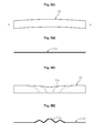
- the band-like glass film 12 in plan view which is being conveyed, is not completely straight in the length direction of the band-like glass film but curved as illustrated in FIG. 5A1 , and the band-like glass film 12 in side view extends in a straight line as illustrated in FIG. 5A2
- the band-like glass film 12 assumes the following form. That is, as illustrated in FIG. 5B1 , distortions or creases are generated in the vicinity of the longitudinal center portion of the band-like glass film 12 in plan view, and as illustrated in FIG. 5B2 , the distortions or creases appear as wavy portions 12a in the vicinity of the longitudinal center portion of the band-like glass film 12 in side view.
- the present invention has a technical object to provide a cleaving apparatus for a band-like glass film and a cleaving method for a band-like glass film, in which at least one surface (effective surface) of the band-like glass film is held in a non-contact state to suppress a situation that wavy portions reach a region in which the band-like glass film is to be cleaved.
- the present invention provides a cleaving apparatus for a band-like glass film, which is configured such that the band-like glass film, which is being conveyed in a longitudinal direction thereof, is cleaved along a conveyance direction thereof using a thermal stress generated through localized heating and cooling of a heated region resulting from the localized heating, the localized heating and the cooling being performed on a preset cleaving line extending along the conveyance direction of the band-like glass film, the cleaving apparatus including: support means for supporting a back surface side of the band-like glass film; and air supply means for supplying air to a front surface of the band-like glass film while supporting, by the support means, the back surface side of the band-like glass film to retain the band-like glass film on the support means at a position on an upstream side of a cleaving region in the conveyance direction, the cleaving region being defined as a region in which the band-like glass film is to be clea
- the band-like glass film is retained on the support means with the air so that the wavy portions can be kept on the upstream side of the position at which the band-like glass film is retained.
- the wavy portions reach the cleaving region for the band-like glass film situated on the downstream side of the position described above.
- the conveyance direction of the band-like glass film be a lateral direction.
- the "lateral direction” does not only include the horizontal direction, but also includes an inclined direction in which the downstream side of the conveyance direction is inclined downward, and an inclined direction in which the downstream side of the conveyance direction is inclined upward.
- a width of air supply from the air supply means be set larger than a width of the band-like glass film.
- the entire widthwise region of the band-like glass film can be retained with the air from the air supply means, and thus the effect of suppressing the situation that the wavy portions reach the cleaving region is more reliably obtained.
- the air supply means be an air knife.
- the air supply means is the air knife.
- the air supply means blow the air in a direction from a position spaced away from the front surface of the band-like glass film on a downstream side in the conveyance direction of the band-like glass film toward a position on the front surface of the band-like glass film on an upstream side in the conveyance direction of the band-like glass film.
- the air supply means be an air float table.
- the band-like glass film is supported in a non-contact state by the air float table, and hence friction is virtually negligible during the conveyance of the band-like glass film. Accordingly, the band-like glass film having the wavy portions generated therein is easily stretchable when the band-like glass film is retained with the air from the air supply means, with the result that a remarkable effect of suppressing the wavy portions can be obtained. Further, both surfaces of the band-like glass film can be held in a non-contact state, and thus it is possible to suppress soiling or damaging to both the surfaces of the band-like glass film.
- the present invention provides a cleaving method for a band-like glass film, in which the band-like glass film, which is being conveyed in a longitudinal direction thereof, is cleaved along a conveyance direction thereof using a thermal stress generated through localized heating and cooling of a heated region resulting from the localized heating, the localized heating and the cooling being performed on a preset cleaving line extending along the conveyance direction of the band-like glass film, the cleaving method including: supporting, by support means, a back surface side of the band-like glass film; and supplying, by air supply means, air to a front surface of the band-like glass film while supporting, by the support means, the back surface side of the band-like glass film to retain the band-like glass film on the support means at a position on an upstream side of a cleaving region in the conveyance direction, the cleaving region being defined as a region in which the band-like glass film is to be
- the situation that the wavy portions reach the region in which the band-like glass film is to be cleaved can be suppressed with at least one surface of the band-like glass film held in a non-contact state.
- the troubles that may occur during the cleaving of the band-like glass film for example, the trouble that the crack in the cleaved portion deviates from the preset cleaving line and meanders or departs from the preset cleaving line.
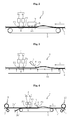
- FIGS. 1A and 1B schematically illustrate a structural example of a cleaving apparatus for a band-like glass film according to the embodiment of the present invention.
- a cleaving apparatus 1 includes, as its main components, a conveyor 3 serving as support means for supporting a band-like glass film 2, thermal stress cleaving means 4 for cleaving the band-like glass film 2 using a thermal stress, and an air knife 5 serving as air supply means for supplying air.
- the band-like glass film 2 is formed by an overflow downdraw method.
- the band-like glass film 2 that is successively formed and conveyed downward from a forming trough 6 has its conveyance direction converted into a horizontal direction during the conveyance. Accordingly, the band-like glass film 2 is conveyed to the cleaving apparatus 1 in a lateral direction indicated by the arrow A (in this embodiment, horizontal direction or substantially horizontal direction).
- the band-like glass film 2 is cut by the thermal stress cleaving means 4 into an available film portion (band-like glass film portion serving as an end product) 2a and unnecessary selvage portions 2b at both ends of the band-like glass film 2.
- a speed of a conveyor belt of the conveyor 3 is synchronized with a conveyance speed of the band-like glass film 2.
- the available film portion 2a is rolled by a roll-up device 8 under a state in which a band-like protective film 7 including a resin film and the like is overlaid on the available film portion 2a.
- the selvage portions 2b are conveyed to a selvage portion processing device (not shown).
- the thermal stress cleaving means 4 performs so-called laser cleaving, and is arranged above the conveyor 3.
- the thermal stress cleaving means 4 includes laser beam applying means 4a for performing localized heating at a heating position P1, and mist water jetting means 4b for performing cooling at a cooling position P2.
- the heating position P1 and the cooling position P2 are situated on a preset cleaving line extending along the conveyance direction of the band-like glass film 2.
- the thermal stress cleaving means 4 performs localized heating and cooling of a heated region resulting from the localized heating, to thereby generate a thermal stress in the band-like glass film 2.
- a crack is propagated along the preset cleaving line, and as a result, the band-like glass film 2 is successively cleaved.
- the region from the heating position P1 to the cooling position P2 corresponds to a cleaving region R, in which the band-like glass film 2 is to be cleaved.
- the air knife 5 is disposed at a position that is spaced upward from the conveyor 3 and situated on an upstream side of the thermal stress cleaving means 4 in the conveyance direction.
- An air blow direction from the air knife 5 to the band-like glass film 2 is set as a direction indicated by the arrow B, that is, a direction inclined from an upper downstream position of the band-like glass film 2 toward a lower upstream side thereof.
- a width of air supply from the air knife 5 is set larger than the width of the band-like glass film 2. Accordingly, the band-like glass film 2 is retained on the conveyor 3 at a position P3 with the air from the air knife 5.
- the cleaving apparatus 1 structured as described above produces the following effects.
- the band-like glass film 2 is retained on an upper surface of the conveyor 3 and stretched at the position P3, with the result that the wavy portions are suppressed at the position P3.
- the position P3 is situated on the upstream side of the cleaving region R in the conveyance direction, and hence it is possible to suppress a situation that the wavy portions of the band-like glass film 2 reach the cleaving region R. Further, an upper surface of the band-like glass film 2, to which air is blown from the air knife 5, is held in a non-contact state. Thus, the upper surface of the band-like glass film 2 is not soiled or damaged.
- An amount of air supply from the air knife 5 per unit area (1 mm 2 ) of an air supply port of the air knife 5 is preferably 0.1 l/min or more, further preferably 0.5 l/min or more.
- the air supply amount per unit area (1 mm 2 ) is, for example, less than 10 l/min.
- equipment cost may unnecessarily increase due to capacity increase of an air supply source.
- An inclination angle ⁇ formed in side view between the air blow direction of the air knife 5 and the conveyance direction of the band-like glass film 2 is preferably 15° to 75°, further preferably 30° to 60°.
- the inclination angle ⁇ is less than 15°, the band-like glass film 2 cannot possibly be retained with air sufficiently.
- the inclination angle ⁇ exceeds 75°, the air supplied from the air knife 5 is likely to flow toward the downstream side.
- the band-like glass film 2 vibrates. Accordingly, part of the band-like glass film 2 in the cleaving region R vibrates, with the result that the cleaving may become unstable.
- a distance L between the heating position P1 and the position P3 along the conveyance direction is preferably 50 mm to 1,000 mm, further preferably 100 mm to 500 mm. From the viewpoint of an installation space of the air knife 5, it is difficult to set the distance L to less than 50 mm. When the distance L exceeds 1,000 mm, the band-like glass film 2 may become wavy again in the region between the heating position P1 and the position P3.
- a height H of the air supply port of the air knife 5 from the front surface of the conveyor belt of the conveyor 3 is preferably 3 mm to 50 mm, further preferably 5 mm to 20 mm.
- the height H is less than 3 mm, in a case where the band-like glass film 2 slightly moves vertically due to vibrations or the like, the band-like glass film 2 may be brought into contact with a tip end of the air knife 5 and, as a result, the band-like glass film 2 may be damaged.
- the height H exceeds 50 mm, air may be diffused and, as a result, the band-like glass film 2 might not be retained sufficiently.
- a width W of air supplied from the air knife 5 is preferably 110% or more of the width of the band-like glass film 2.
- the width W of air is, for example, less than 150% of the width of the band-like glass film 2.
- the width W of air is 150% or more of the width of the band-like glass film 2
- the equipment cost may unnecessarily increase due to the capacity increase of the air supply source, and the installation space of the air knife 5 may unnecessarily increase.
- the present invention is not limited to the above-mentioned embodiment.
- other air supply means such as an air float device 9 illustrated in FIG. 2 may be used in place of the air knife 5.
- an air supply source having a larger capacity than that of the air knife 5 is necessary.
- the air hitting against the band-like glass film 2 is likely to flow toward the downstream side, and hence the above-mentioned vibrations are likely to occur.
- the support means for the band-like glass film 2 is not limited to the conveyor 3.
- the support means may be a simple plate-like member such as a resin plate, or an air float table 10 illustrated in FIG. 3 .
- the simple plate-like member the plate-like member slides in contact with the band-like glass film 2, and hence the band-like glass film 2 may be damaged on the back surface side thereof.
- the air float table 10 does not come into contact with the band-like glass film 2, and hence the band-like glass film 2 is not damaged on the back surface side thereof.
- friction is virtually negligible, and hence, when the air from the air supply means hits against the band-like glass film 2, the band-like glass film 2 is easily stretchable, with the result that the effect of suppressing the wavy portions is enhanced.
- the cleaving apparatus 1 is used for so-called primary cutting processing involving the steps from forming of the band-like glass film 2 to rolling of the band-like glass film 2, but the present invention is not limited thereto.
- the cleaving apparatus 1 may be used for so-called secondary cutting processing involving further cleaving of a band-like glass film 2' in a rolled state.
- the band-like glass film 2' to be cleaved by the cleaving apparatus 1 is unrolled from an unrolling device 11 while removing the band-like protective film 7, and is cleaved into a new available film portion 2a' and selvage portions 2b'.
- Other respects than the above are substantially the same as in the above-mentioned embodiment, and hence similar components are represented by the same reference symbols to omit description thereof.
- a roll of the band-like glass film 2' having a thickness of 70 ⁇ m, a width of 800 mm, and a length of 200 m was mounted onto the unrolling device 11, and the band-like glass film 2' was cut and separated into the available film portion 2a' having a width of 600 mm and the selvage portions 2b' situated at both ends of the band-like glass film 2' and each having a width of 100 mm.
- the available film portion 2a' was rolled by the roll-up device 8.
- the air blow port had a dimension of 1,000 mm in the width direction of the band-like glass film, and 0.5 mm in the conveyance direction of the band-like glass film.
- the total flow rate of air to be supplied was 1,000 l/min, and the flow rate per unit area (1 mm 2 ) of the air supply port of the air knife 5 was 2 l/min. Further, the inclination angle ⁇ was 45°, the distance L was 500 mm, and the height H was 10 mm. As a result of performing laser cleaving on the band-like glass film 2' under the conditions described above, the band-like glass film 2' was successfully cut along its entire length, and the available film portion 2a' was successfully rolled. Further, the maximum value of a standard deviation value of a meandering amount in the cleaved surface of the available film portion 2a' was 15 ⁇ m.
- the standard deviation value of the meandering amount in the cleaved surface of the available film portion 2a' was calculated in the following manner. First, both end portions of the available film portion 2a' were each photographed using a CCD camera from a thickness direction of the available film portion 2a' while conveying the available film portion 2a'. Subsequently, the photographed image was divided into 30-mm lengthwise regions of the available film portion 2a'. For each divided image, the standard deviation value was calculated based on a difference between an average position and each position of all pixels in the width direction of the available film portion 2a', the pixels including an end surface (cleaved surface) of the available film portion 2a'. Note that, the 30-mm lengthwise region of the available film portion 2a' in the image photographed by the CCD camera is divided into 1,600 pixels. As for the width direction, the photographed image is divided into 1,200 pixels.
- the cleaving apparatus for a band-like glass film and the cleaving method for a band-like glass film according to the example of the present invention have effectively suppressed the situation that the wavy portions reach the cleaving region R, in which the band-like glass film 2' is to be cleaved.
Landscapes
- Chemical & Material Sciences (AREA)
- Engineering & Computer Science (AREA)
- Physics & Mathematics (AREA)
- Materials Engineering (AREA)
- Organic Chemistry (AREA)
- Optics & Photonics (AREA)
- Thermal Sciences (AREA)
- Toxicology (AREA)
- Health & Medical Sciences (AREA)
- Nonlinear Science (AREA)
- Plasma & Fusion (AREA)
- Mechanical Engineering (AREA)
- Mathematical Physics (AREA)
- Crystallography & Structural Chemistry (AREA)
- General Physics & Mathematics (AREA)
- Re-Forming, After-Treatment, Cutting And Transporting Of Glass Products (AREA)
- Liquid Crystal (AREA)
Abstract
Description
- The present invention relates to a technology for cleaving a band-like glass film, which is to be used for a flat panel display, a solar cell, an organic light-emitting diode (OLED) illumination device, or the like, along a conveyance direction thereof.
- In recent years, flat panel displays (FPDs) have become mainstream as image display devices, the FPDs being typified by a liquid crystal display, a plasma display, an OLED display, and the like. Further, progress is being made toward reduction in weight of those FPDs. Therefore, glass substrates to be used for the FPDs are also currently becoming thinner (formed as a glass film).
- Further, there is a growing use of an organic light-emitting diode as a plane light source for interior illumination, which emits only monochrome (for example, white) light. When this type of illumination device includes a glass substrate having flexibility, a light-emitting surface of the illumination device is freely deformable. Therefore, from the viewpoint of ensuring sufficient flexibility, it is also promoted to further thin the glass substrate to be used for the illumination device.
- A glass substrate that is thinned to have a thickness of 300 µm or less (glass film) is generally obtained by forming a band-like glass film and then cutting the band-like glass film into a predetermined size. The band-like glass film has flexibility to such a degree that the band-like glass film is not broken even when the band-like glass film is rolled around a roll core, and accordingly the band-like glass film can be rolled into a roll shape to serve as a glass roll. When the band-like glass film is rolled into a roll shape as described above, processing of cutting the band-like glass film into a predetermined width and various kinds of film formation processing can be performed in a roll-to-roll process (process of unrolling one glass roll to obtain the band-like glass film and simultaneously rolling the glass film subjected to various kinds of processing into another glass roll). As a result, production efficiency of displays and illumination devices can be enhanced greatly.
- The glass roll to be charged into production equipment (roll-to-roll process) for displays and illumination devices is obtained in the following manner. That is, in a band-like glass film, which is formed of molten glass into a thin sheet shape by an overflow downdraw method or a slot downdraw method, unnecessary portions at both widthwise ends thereof (selvage portions) are cut (primary cutting processing), and the resultant band-like glass film is rolled around a core (see Patent Literature 1). Further, if necessary, the glass roll that is formed and rolled by the above-mentioned method is charged into the roll-to-roll process and cut into a desired width (secondary cutting processing).
- For the primary cutting processing and the secondary cutting processing, for example, a cutting method involving laser cleaving is employed. In the method involving the laser cleaving, the band-like glass film is successively cleaved by propagating, along a preset cleaving line extending in a conveyance direction of the band-like glass film, an initial crack formed at a leading end portion of the preset cleaving line using a thermal stress generated in the band-like glass film through localized heating using a laser and cooling of a heated region resulting from the localized heating, which are performed along the preset cleaving line.
-
- Patent Literature 1:
JP 2010-132531 A - Patent Literature 2:
JP 2000-109252 A - Patent Literature 3:
JP 8-175726 A - Patent Literature 4:
JP 60-076318 A - By the way, the above-mentioned laser cleaving may cause, during the successive cleaving of the band-like glass film, a situation that the crack in the cleaved portion deviates from the preset cleaving line and meanders so that the cut surface (cleaved surface) of the band-like glass film becomes rough, or a situation that the crack in the cleaved portion departs from the preset cleaving line so that the crack is propagated in a width direction of the band-like glass film. Further, there arises a problem in that the laser cleaving of the band-like glass film stops due to the above-mentioned situations. This is because the band-like glass film becomes wavy in its cleaved region for the following reasons.
- That is, the first reason is that the band-like glass film formed by the overflow downdraw method or the slot downdraw method slightly meanders in the width or thickness direction thereof. Specifically, the band-like glass film in plan view is not completely straight in a length direction thereof but slightly curved, or the band-like glass film in side view is not completely flat but wavy in an entire or partial widthwise region. Further, the second reason is that slight misalignment occurs in a conveyance device. Specifically, shafts of guide rollers are misaligned or the degree of linear motion of a conveyor is deteriorated so that creases are generated in the band-like glass film.
- In this case, when the material of the film is a web material having stretchability, such as a resin, even if distortions or creases are generated for any one of the reasons described above, the band-like film is conveyed while applying an appropriate tensile force so that the apparent distortions or creases are eliminated and thus the wavy portions of the band-like film during the conveyance can be eliminated. However, the stretchability of the band-like glass film is extremely low, and hence, even when the band-like film is conveyed while applying the tensile force, the apparent distortions or creases of the band-like glass film are not eliminated. On the contrary, the wavy portions of the band-like glass film may further be developed.
- For example, in a case where a band-
like glass film 12 in plan view, which is being conveyed, is not completely straight in the length direction of the band-like glass film but curved as illustrated inFIG. 5A1 , and the band-like glass film 12 in side view extends in a straight line as illustrated inFIG. 5A2 , when a tensile force is applied in the conveyance direction as indicated by the arrows ofFIG. 5A1 , the band-like glass film 12 assumes the following form. That is, as illustrated inFIG. 5B1 , distortions or creases are generated in the vicinity of the longitudinal center portion of the band-like glass film 12 in plan view, and as illustrated inFIG. 5B2 , the distortions or creases appear aswavy portions 12a in the vicinity of the longitudinal center portion of the band-like glass film 12 in side view. - As a method of smoothing the creases of the web, many kinds of crease smoothing rollers or crease smoothing devices are proposed (see
Patent Literatures 2 to 4). However, all the above-mentioned crease smoothing rollers or devices are provided to eliminate only the creases generated in the width direction of the web, and do not have any effect of smoothing the creases (wavy portions) which may be generated in the conveyance direction of the band-like glass film during the conveyance thereof. - Further, there may be conceived a method of nipping the band-like glass film between nip rollers to prevent a situation that the wavy portions of the band-like glass film reach the cleaving region. In this case, however, both surfaces of the band-like glass film are brought into contact with the nip rollers, which leads to a problem in that the band-like glass film is soiled or damaged on an effective surface (surface to be subjected to various kinds of processing such as film formation) thereof.
- In view of the above-mentioned circumstances, the present invention has a technical object to provide a cleaving apparatus for a band-like glass film and a cleaving method for a band-like glass film, in which at least one surface (effective surface) of the band-like glass film is held in a non-contact state to suppress a situation that wavy portions reach a region in which the band-like glass film is to be cleaved.
- In order to achieve the above-mentioned object, the present invention provides a cleaving apparatus for a band-like glass film, which is configured such that the band-like glass film, which is being conveyed in a longitudinal direction thereof, is cleaved along a conveyance direction thereof using a thermal stress generated through localized heating and cooling of a heated region resulting from the localized heating, the localized heating and the cooling being performed on a preset cleaving line extending along the conveyance direction of the band-like glass film, the cleaving apparatus including: support means for supporting a back surface side of the band-like glass film; and air supply means for supplying air to a front surface of the band-like glass film while supporting, by the support means, the back surface side of the band-like glass film to retain the band-like glass film on the support means at a position on an upstream side of a cleaving region in the conveyance direction, the cleaving region being defined as a region in which the band-like glass film is to be cleaved.
- With this structure, the band-like glass film is retained on the support means with the air so that the wavy portions can be kept on the upstream side of the position at which the band-like glass film is retained. Thus, it is possible to suppress the situation that the wavy portions reach the cleaving region for the band-like glass film situated on the downstream side of the position described above. Accordingly, it is possible to effectively avoid the situation that may occur during the cleaving of the band-like glass film, that is, the situation that the crack in the cleaved portion deviates from the preset cleaving line and meanders so that the cleaved surface becomes rough, or the situation that the crack in the cleaved portion departs from the preset cleaving line so that the crack is propagated in the width direction of the band-like glass film. Further, one surface (front surface) of the band-like glass film, to which the air is blown from the air supply means so as to retain the band-like glass film, is held in a non-contact state. Thus, troubles such as soiling or damaging to the one surface do not easily occur. Note that, it is preferred that the conveyance direction of the band-like glass film be a lateral direction. In this case, the "lateral direction" does not only include the horizontal direction, but also includes an inclined direction in which the downstream side of the conveyance direction is inclined downward, and an inclined direction in which the downstream side of the conveyance direction is inclined upward.
- In the above-mentioned structure, it is preferred that a width of air supply from the air supply means be set larger than a width of the band-like glass film.
- With this structure, the entire widthwise region of the band-like glass film can be retained with the air from the air supply means, and thus the effect of suppressing the situation that the wavy portions reach the cleaving region is more reliably obtained.
- In any one of the above-mentioned structures, it is preferred that the air supply means be an air knife.
- With this structure, the air supply means is the air knife. Thus, it is possible to intensively retain only the portion of the band-like glass film intended to be retained, and to reduce the total flow rate of air to be supplied.
- In any one of the above-mentioned structures, it is preferred that the air supply means blow the air in a direction from a position spaced away from the front surface of the band-like glass film on a downstream side in the conveyance direction of the band-like glass film toward a position on the front surface of the band-like glass film on an upstream side in the conveyance direction of the band-like glass film.
- With this structure, it is possible to suppress an adverse effect that is caused when the air supplied from the air knife flows toward the downstream side in the conveyance direction of the band-like glass film. As the adverse effect, unstable cleaving is taken as an example, in which the band-like glass film vibrates due to the fact that the air flowing toward the downstream side in the conveyance direction enters the opposite surface side through the cleaved portion of the band-like glass film.
- In any one of the above-mentioned structures, it is preferred that the air supply means be an air float table.
- With this structure, the band-like glass film is supported in a non-contact state by the air float table, and hence friction is virtually negligible during the conveyance of the band-like glass film. Accordingly, the band-like glass film having the wavy portions generated therein is easily stretchable when the band-like glass film is retained with the air from the air supply means, with the result that a remarkable effect of suppressing the wavy portions can be obtained. Further, both surfaces of the band-like glass film can be held in a non-contact state, and thus it is possible to suppress soiling or damaging to both the surfaces of the band-like glass film.
- Further, in order to achieve the above-mentioned object, the present invention provides a cleaving method for a band-like glass film, in which the band-like glass film, which is being conveyed in a longitudinal direction thereof, is cleaved along a conveyance direction thereof using a thermal stress generated through localized heating and cooling of a heated region resulting from the localized heating, the localized heating and the cooling being performed on a preset cleaving line extending along the conveyance direction of the band-like glass film, the cleaving method including: supporting, by support means, a back surface side of the band-like glass film; and supplying, by air supply means, air to a front surface of the band-like glass film while supporting, by the support means, the back surface side of the band-like glass film to retain the band-like glass film on the support means at a position on an upstream side of a cleaving region in the conveyance direction, the cleaving region being defined as a region in which the band-like glass film is to be cleaved.
- The constituent features of this method are substantially the same as those of the apparatus according to the present invention, which is described in the beginning of this section. Hence, the matters including the action and effect are substantially the same as those already described with regard to this apparatus.
- As described above, according to the present invention, the situation that the wavy portions reach the region in which the band-like glass film is to be cleaved can be suppressed with at least one surface of the band-like glass film held in a non-contact state. Thus, it is possible to effectively avoid, with appropriate protection of the effective surface (front surface) of the band-like glass film, the troubles that may occur during the cleaving of the band-like glass film, for example, the trouble that the crack in the cleaved portion deviates from the preset cleaving line and meanders or departs from the preset cleaving line.
-
- [
FIG. 1A ] A side view illustrating a structural example of a cleaving apparatus for a band-like glass film according to an embodiment of the present invention. - [
FIG. 1B ] A plan view illustrating the structural example of the cleaving apparatus for a band-like glass film according to the embodiment of the present invention. - [
FIG. 2 ] A side view illustrating another example of air supply means. - [
FIG. 3 ] A side view illustrating another example of support means. - [
FIG. 4 ] A side view illustrating another use example of the cleaving apparatus for a band-like glass film according to the embodiment of the present invention. - [
FIG. 5A1 ] A schematic plan view of a band-like glass film before a tensile force is applied. - [
FIG. 5A2 ] A schematic side view of the band-like glass film before the tensile force is applied. - [
FIG. 5B1 ] A schematic plan view of the band-like glass film after the tensile force is applied. - [
FIG. 5B2 ] A schematic side view of the band-like glass film after the tensile force is applied. - Hereinafter, an embodiment of the present invention is described with reference to the drawings.
-
FIGS. 1A and 1B schematically illustrate a structural example of a cleaving apparatus for a band-like glass film according to the embodiment of the present invention. As illustrated inFIGS. 1A and 1B , a cleaving apparatus 1 according to the embodiment of the present invention includes, as its main components, aconveyor 3 serving as support means for supporting a band-like glass film 2, thermal stress cleaving means 4 for cleaving the band-like glass film 2 using a thermal stress, and anair knife 5 serving as air supply means for supplying air. - In this embodiment, the band-
like glass film 2 is formed by an overflow downdraw method. The band-like glass film 2 that is successively formed and conveyed downward from a formingtrough 6 has its conveyance direction converted into a horizontal direction during the conveyance. Accordingly, the band-like glass film 2 is conveyed to the cleaving apparatus 1 in a lateral direction indicated by the arrow A (in this embodiment, horizontal direction or substantially horizontal direction). Then, under a state in which the band-like glass film 2 that has reached the cleaving apparatus 1 is supported by theconveyor 3, the band-like glass film 2 is cut by the thermal stress cleaving means 4 into an available film portion (band-like glass film portion serving as an end product) 2a andunnecessary selvage portions 2b at both ends of the band-like glass film 2. At this time, a speed of a conveyor belt of theconveyor 3 is synchronized with a conveyance speed of the band-like glass film 2. Theavailable film portion 2a is rolled by a roll-up device 8 under a state in which a band-likeprotective film 7 including a resin film and the like is overlaid on theavailable film portion 2a. Theselvage portions 2b are conveyed to a selvage portion processing device (not shown). - The thermal stress cleaving means 4 performs so-called laser cleaving, and is arranged above the
conveyor 3. The thermal stress cleaving means 4 includes laserbeam applying means 4a for performing localized heating at a heating position P1, and mist water jetting means 4b for performing cooling at a cooling position P2. The heating position P1 and the cooling position P2 are situated on a preset cleaving line extending along the conveyance direction of the band-like glass film 2. The thermal stress cleaving means 4 performs localized heating and cooling of a heated region resulting from the localized heating, to thereby generate a thermal stress in the band-like glass film 2. In accordance with the generation of the thermal stress, a crack is propagated along the preset cleaving line, and as a result, the band-like glass film 2 is successively cleaved. The region from the heating position P1 to the cooling position P2 corresponds to a cleaving region R, in which the band-like glass film 2 is to be cleaved. - The
air knife 5 is disposed at a position that is spaced upward from theconveyor 3 and situated on an upstream side of the thermal stress cleaving means 4 in the conveyance direction. An air blow direction from theair knife 5 to the band-like glass film 2 is set as a direction indicated by the arrow B, that is, a direction inclined from an upper downstream position of the band-like glass film 2 toward a lower upstream side thereof. Further, a width of air supply from theair knife 5 is set larger than the width of the band-like glass film 2. Accordingly, the band-like glass film 2 is retained on theconveyor 3 at a position P3 with the air from theair knife 5. - The cleaving apparatus 1 structured as described above produces the following effects.
- Even when wavy portions are generated in the band-
like glass film 2 on the upstream side of the position P3, the band-like glass film 2 is retained on an upper surface of theconveyor 3 and stretched at the position P3, with the result that the wavy portions are suppressed at the position P3. The position P3 is situated on the upstream side of the cleaving region R in the conveyance direction, and hence it is possible to suppress a situation that the wavy portions of the band-like glass film 2 reach the cleaving region R. Further, an upper surface of the band-like glass film 2, to which air is blown from theair knife 5, is held in a non-contact state. Thus, the upper surface of the band-like glass film 2 is not soiled or damaged. - Hereinafter, the
air knife 5 is further described in detail. - An amount of air supply from the
air knife 5 per unit area (1 mm2) of an air supply port of theair knife 5 is preferably 0.1 l/min or more, further preferably 0.5 l/min or more. When the air supply amount is less than 0.1 l/min, the band-like glass film 2 cannot possibly be retained with air sufficiently. On the other hand, the air supply amount per unit area (1 mm2) is, for example, less than 10 l/min. When the air supply amount is 10 l/min or more, equipment cost may unnecessarily increase due to capacity increase of an air supply source. - An inclination angle θ formed in side view between the air blow direction of the
air knife 5 and the conveyance direction of the band-like glass film 2 is preferably 15° to 75°, further preferably 30° to 60°. When the inclination angle θ is less than 15°, the band-like glass film 2 cannot possibly be retained with air sufficiently. On the other hand, when the inclination angle θ exceeds 75°, the air supplied from theair knife 5 is likely to flow toward the downstream side. When the air flowing toward the downstream side enters a back surface side of the band-like glass film 2 through the cleaved portion of the band-like glass film 2, the band-like glass film 2 vibrates. Accordingly, part of the band-like glass film 2 in the cleaving region R vibrates, with the result that the cleaving may become unstable. - A distance L between the heating position P1 and the position P3 along the conveyance direction is preferably 50 mm to 1,000 mm, further preferably 100 mm to 500 mm. From the viewpoint of an installation space of the
air knife 5, it is difficult to set the distance L to less than 50 mm. When the distance L exceeds 1,000 mm, the band-like glass film 2 may become wavy again in the region between the heating position P1 and the position P3. - A height H of the air supply port of the
air knife 5 from the front surface of the conveyor belt of theconveyor 3 is preferably 3 mm to 50 mm, further preferably 5 mm to 20 mm. When the height H is less than 3 mm, in a case where the band-like glass film 2 slightly moves vertically due to vibrations or the like, the band-like glass film 2 may be brought into contact with a tip end of theair knife 5 and, as a result, the band-like glass film 2 may be damaged. When the height H exceeds 50 mm, air may be diffused and, as a result, the band-like glass film 2 might not be retained sufficiently. - A width W of air supplied from the
air knife 5 is preferably 110% or more of the width of the band-like glass film 2. When the width W of air is less than 110% of the width of the band-like glass film 2, the ends of the band-like glass film might not be retained sufficiently, and therefore the wavy portions of the band-like glass film 2 might not be suppressed sufficiently. On the other hand, the width W of air is, for example, less than 150% of the width of the band-like glass film 2. When the width W of air is 150% or more of the width of the band-like glass film 2, the equipment cost may unnecessarily increase due to the capacity increase of the air supply source, and the installation space of theair knife 5 may unnecessarily increase. - The present invention is not limited to the above-mentioned embodiment. For example, other air supply means such as an
air float device 9 illustrated inFIG. 2 may be used in place of theair knife 5. However, in the case of theair float device 9, in order to supply air at a flow rate of 0.1 l/min or more per unit area (1 mm2) of the air supply port, an air supply source having a larger capacity than that of theair knife 5 is necessary. Further, in the case of theair float device 9, the air hitting against the band-like glass film 2 is likely to flow toward the downstream side, and hence the above-mentioned vibrations are likely to occur. - Further, the support means for the band-
like glass film 2 is not limited to theconveyor 3. For example, the support means may be a simple plate-like member such as a resin plate, or an air float table 10 illustrated inFIG. 3 . However, in the case of the simple plate-like member, the plate-like member slides in contact with the band-like glass film 2, and hence the band-like glass film 2 may be damaged on the back surface side thereof. On the other hand, in the case of the air float table 10, the air float table 10 does not come into contact with the band-like glass film 2, and hence the band-like glass film 2 is not damaged on the back surface side thereof. Further, friction is virtually negligible, and hence, when the air from the air supply means hits against the band-like glass film 2, the band-like glass film 2 is easily stretchable, with the result that the effect of suppressing the wavy portions is enhanced. - Further, in the above-mentioned embodiment, the cleaving apparatus 1 is used for so-called primary cutting processing involving the steps from forming of the band-
like glass film 2 to rolling of the band-like glass film 2, but the present invention is not limited thereto. For example, as illustrated inFIG. 4 , the cleaving apparatus 1 may be used for so-called secondary cutting processing involving further cleaving of a band-like glass film 2' in a rolled state. The band-like glass film 2' to be cleaved by the cleaving apparatus 1 is unrolled from an unrollingdevice 11 while removing the band-likeprotective film 7, and is cleaved into a newavailable film portion 2a' andselvage portions 2b'. Other respects than the above are substantially the same as in the above-mentioned embodiment, and hence similar components are represented by the same reference symbols to omit description thereof. - In the structural example of the cleaving apparatus illustrated in
FIG. 4 , a roll of the band-like glass film 2' having a thickness of 70 µm, a width of 800 mm, and a length of 200 m was mounted onto the unrollingdevice 11, and the band-like glass film 2' was cut and separated into theavailable film portion 2a' having a width of 600 mm and theselvage portions 2b' situated at both ends of the band-like glass film 2' and each having a width of 100 mm. Theavailable film portion 2a' was rolled by the roll-up device 8. The air blow port had a dimension of 1,000 mm in the width direction of the band-like glass film, and 0.5 mm in the conveyance direction of the band-like glass film. Further, the total flow rate of air to be supplied was 1,000 l/min, and the flow rate per unit area (1 mm2) of the air supply port of theair knife 5 was 2 l/min. Further, the inclination angle θ was 45°, the distance L was 500 mm, and the height H was 10 mm. As a result of performing laser cleaving on the band-like glass film 2' under the conditions described above, the band-like glass film 2' was successfully cut along its entire length, and theavailable film portion 2a' was successfully rolled. Further, the maximum value of a standard deviation value of a meandering amount in the cleaved surface of theavailable film portion 2a' was 15 µm. - The standard deviation value of the meandering amount in the cleaved surface of the
available film portion 2a' was calculated in the following manner. First, both end portions of theavailable film portion 2a' were each photographed using a CCD camera from a thickness direction of theavailable film portion 2a' while conveying theavailable film portion 2a'. Subsequently, the photographed image was divided into 30-mm lengthwise regions of theavailable film portion 2a'. For each divided image, the standard deviation value was calculated based on a difference between an average position and each position of all pixels in the width direction of theavailable film portion 2a', the pixels including an end surface (cleaved surface) of theavailable film portion 2a'. Note that, the 30-mm lengthwise region of theavailable film portion 2a' in the image photographed by the CCD camera is divided into 1,600 pixels. As for the width direction, the photographed image is divided into 1,200 pixels. - As a comparative example, laser cleaving was performed on the band-like glass film 2' under the same conditions as in the above-mentioned example, except that the
air knife 5 was not used. As a result, when the band-like glass film 2' was cleaved in a region of about 35 m in length, the crack in the cleaving region R was propagated in the width direction of the band-like glass film 2'. Then, theavailable film portion 2a' was cut in the width direction and the cleaving stopped. Further, the maximum value of the standard deviation value of the meandering amount in the cleaved surface of theavailable film portion 2a', which was cleaved into a width of 600 mm before the cleaving stopped, was 132 µm. - As is apparent from the comparison between the result of the example and the result of the comparative example, the cleaving apparatus for a band-like glass film and the cleaving method for a band-like glass film according to the example of the present invention have effectively suppressed the situation that the wavy portions reach the cleaving region R, in which the band-like glass film 2' is to be cleaved.
- The present invention is not limited to the above description, and various modifications may be made within the scope of the technical idea thereof.
-
- 1
- cleaving apparatus for band-like glass film
- 2, 2'
- band-like glass film
- 3
- conveyor (support means)
- 5
- air knife (air supply means)
- 9
- air float device (air supply means)
- 10
- air float table (support means)
- R
- cleaving region
Claims (6)
- A cleaving apparatus for a band-like glass film, which is configured such that the band-like glass film, which is being conveyed in a longitudinal direction thereof, is cleaved along a conveyance direction thereof using a thermal stress generated through localized heating and cooling of a heated region resulting from the localized heating, the localized heating and the cooling being performed on a preset cleaving line extending along the conveyance direction of the band-like glass film,
the cleaving apparatus comprising:support means for supporting a back surface side of the band-like glass film; andair supply means for supplying air to a front surface of the band-like glass film while supporting, by the support means, the back surface side of the band-like glass film to retain the band-like glass film on the support means at a position on an upstream side of a cleaving region in the conveyance direction, the cleaving region being defined as a region in which the band-like glass film is to be cleaved. - The cleaving apparatus for a band-like glass film according to claim 1, wherein a width of air supply from the air supply means is set larger than a width of the band-like glass film.
- The cleaving apparatus for a band-like glass film according to claim 1 or 2, wherein the air supply means comprises an air knife.
- The cleaving apparatus for a band-like glass film according to any one of claims 1 to 3, wherein the air supply means blows the air in a direction from a position spaced away from the front surface of the band-like glass film on a downstream side in the conveyance direction of the band-like glass film toward a position on the front surface of the band-like glass film on an upstream side in the conveyance direction of the band-like glass film.
- The cleaving apparatus for a band-like glass film according to any one of claims 1 to 4, wherein the support means comprises an air float table.
- A cleaving method for a band-like glass film, in which the band-like glass film, which is being conveyed in a longitudinal direction thereof, is cleaved along a conveyance direction thereof using a thermal stress generated through localized heating and cooling of a heated region resulting from the localized heating, the localized heating and the cooling being performed on a preset cleaving line extending along the conveyance direction of the band-like glass film,
the cleaving method comprising:supporting, by support means, a back surface side of the band-like glass film; andsupplying, by air supply means, air to a front surface of the band-like glass film while supporting, by the support means, the back surface side of the band-like glass film to retain the band-like glass film on the support means at a position on an upstream side of a cleaving region in the conveyance direction, the cleaving region being defined as a region in which the band-like glass film is to be cleaved.
Applications Claiming Priority (2)
| Application Number | Priority Date | Filing Date | Title |
|---|---|---|---|
| JP2010260275A JP5617556B2 (en) | 2010-11-22 | 2010-11-22 | Strip glass film cleaving apparatus and strip glass film cleaving method |
| PCT/JP2011/076227 WO2012070422A1 (en) | 2010-11-22 | 2011-11-15 | Device for cleaving strip-shaped glass film and method for cleaving strip-shaped glass film |
Publications (3)
| Publication Number | Publication Date |
|---|---|
| EP2570395A1 true EP2570395A1 (en) | 2013-03-20 |
| EP2570395A4 EP2570395A4 (en) | 2013-12-11 |
| EP2570395B1 EP2570395B1 (en) | 2015-03-04 |
Family
ID=46125725
Family Applications (1)
| Application Number | Title | Priority Date | Filing Date |
|---|---|---|---|
| EP11843737.5A Not-in-force EP2570395B1 (en) | 2010-11-22 | 2011-11-15 | Device for cleaving strip-shaped glass film and method for cleaving strip-shaped glass film |
Country Status (7)
| Country | Link |
|---|---|
| US (1) | US8769989B2 (en) |
| EP (1) | EP2570395B1 (en) |
| JP (1) | JP5617556B2 (en) |
| KR (1) | KR101804192B1 (en) |
| CN (1) | CN102985381B (en) |
| TW (1) | TWI488820B (en) |
| WO (1) | WO2012070422A1 (en) |
Families Citing this family (71)
| Publication number | Priority date | Publication date | Assignee | Title |
|---|---|---|---|---|
| US20020128067A1 (en) | 2001-03-09 | 2002-09-12 | Victor Keith Blanco | Method and apparatus for creating and playing soundtracks in a gaming system |
| KR20120046734A (en) * | 2009-08-07 | 2012-05-10 | 아사히 가라스 가부시키가이샤 | Method for manufacturing ultra-thin glass substrate |
| KR101800224B1 (en) * | 2011-06-08 | 2017-11-22 | 니폰 덴키 가라스 가부시키가이샤 | Method for cutting plate-like glass, and cutting device therefor |
| TWI586612B (en) * | 2011-11-18 | 2017-06-11 | 康寧公司 | Apparatus and method for trimming a moving glass ribbon |
| TWI597245B (en) * | 2012-09-25 | 2017-09-01 | 康寧公司 | Methods of processing a continuous glass ribbon |
| US9216924B2 (en) * | 2012-11-09 | 2015-12-22 | Corning Incorporated | Methods of processing a glass ribbon |
| JP6108175B2 (en) * | 2012-11-09 | 2017-04-05 | 日本電気硝子株式会社 | Initial crack forming apparatus and forming method |
| US9643878B2 (en) * | 2012-11-13 | 2017-05-09 | Nippon Electric Glass Co., Ltd. | Sheet glass manufacturing method and manufacturing device |
| WO2014079478A1 (en) | 2012-11-20 | 2014-05-30 | Light In Light Srl | High speed laser processing of transparent materials |
| US9834389B2 (en) * | 2012-11-29 | 2017-12-05 | Corning Incorporated | Methods and apparatus for fabricating glass ribbon of varying widths |
| EP2754524B1 (en) | 2013-01-15 | 2015-11-25 | Corning Laser Technologies GmbH | Method of and apparatus for laser based processing of flat substrates being wafer or glass element using a laser beam line |
| KR101948382B1 (en) | 2013-01-30 | 2019-02-14 | 코닝 인코포레이티드 | Apparatus and methods for continuous laser cutting of flexible glass |
| EP2781296B1 (en) | 2013-03-21 | 2020-10-21 | Corning Laser Technologies GmbH | Device and method for cutting out contours from flat substrates using a laser |
| DE102013108308A1 (en) * | 2013-08-01 | 2015-02-19 | Schott Ag | Method and device for detecting tape rolls made of brittle-hard or brittle-breaking, at least partially transparent material, and their use |
| JP6112301B2 (en) * | 2013-08-28 | 2017-04-12 | 日本電気硝子株式会社 | Glass film ribbon manufacturing apparatus, glass film ribbon manufacturing method, and glass roll |
| CN107382048B (en) * | 2013-08-28 | 2020-03-27 | 日本电气硝子株式会社 | Glass film tape manufacturing method and glass film tape manufacturing device |
| JP6331087B2 (en) * | 2013-08-28 | 2018-05-30 | 日本電気硝子株式会社 | Glass film ribbon manufacturing method and glass film ribbon manufacturing apparatus |
| KR102221540B1 (en) | 2013-08-28 | 2021-03-02 | 니폰 덴키 가라스 가부시키가이샤 | Glass film ribbon manufacturing method and glass film ribbon manufacturing device |
| WO2015084668A1 (en) | 2013-12-03 | 2015-06-11 | Corning Incorporated | Apparatus and method for severing a glass sheet |
| WO2015084670A1 (en) * | 2013-12-03 | 2015-06-11 | Corning Incorporated | Apparatus and method for severing a moving ribbon of inorganic material |
| US9850160B2 (en) | 2013-12-17 | 2017-12-26 | Corning Incorporated | Laser cutting of display glass compositions |
| US10293436B2 (en) | 2013-12-17 | 2019-05-21 | Corning Incorporated | Method for rapid laser drilling of holes in glass and products made therefrom |
| US9815730B2 (en) | 2013-12-17 | 2017-11-14 | Corning Incorporated | Processing 3D shaped transparent brittle substrate |
| US11556039B2 (en) | 2013-12-17 | 2023-01-17 | Corning Incorporated | Electrochromic coated glass articles and methods for laser processing the same |
| US10442719B2 (en) | 2013-12-17 | 2019-10-15 | Corning Incorporated | Edge chamfering methods |
| US9701563B2 (en) | 2013-12-17 | 2017-07-11 | Corning Incorporated | Laser cut composite glass article and method of cutting |
| US9676167B2 (en) | 2013-12-17 | 2017-06-13 | Corning Incorporated | Laser processing of sapphire substrate and related applications |
| US20150165560A1 (en) | 2013-12-17 | 2015-06-18 | Corning Incorporated | Laser processing of slots and holes |
| JP6288604B2 (en) * | 2014-01-29 | 2018-03-07 | 旭硝子株式会社 | Manufacturing method of glass plate |
| KR102445217B1 (en) | 2014-07-08 | 2022-09-20 | 코닝 인코포레이티드 | Method and apparatus for laser processing material |
| WO2016010949A1 (en) | 2014-07-14 | 2016-01-21 | Corning Incorporated | Method and system for forming perforations |
| EP3536440A1 (en) | 2014-07-14 | 2019-09-11 | Corning Incorporated | Glass article with a defect pattern |
| WO2016010991A1 (en) | 2014-07-14 | 2016-01-21 | Corning Incorporated | Interface block; system for and method of cutting a substrate being transparent within a range of wavelengths using such interface block |
| LT3169477T (en) * | 2014-07-14 | 2020-05-25 | Corning Incorporated | System for and method of processing transparent materials using laser beam focal lines adjustable in length and diameter |
| US10047001B2 (en) | 2014-12-04 | 2018-08-14 | Corning Incorporated | Glass cutting systems and methods using non-diffracting laser beams |
| JP2018507154A (en) | 2015-01-12 | 2018-03-15 | コーニング インコーポレイテッド | Laser cutting of thermally enhanced substrates using multi-photon absorption method |
| JP6424674B2 (en) * | 2015-02-25 | 2018-11-21 | 日本電気硝子株式会社 | Cutting method of glass film |
| JP2018512362A (en) * | 2015-03-18 | 2018-05-17 | コーニング インコーポレイテッド | Method and apparatus for removing the edge of a glass ribbon |
| WO2016154284A1 (en) | 2015-03-24 | 2016-09-29 | Corning Incorporated | Laser cutting and processing of display glass compositions |
| DE102015104815A1 (en) * | 2015-03-27 | 2016-09-29 | Schott Ag | Method and apparatus for continuous separation of glass |
| CN107666983B (en) | 2015-03-27 | 2020-10-02 | 康宁股份有限公司 | Breathable window and method of making the same |
| JP6468460B2 (en) * | 2015-04-16 | 2019-02-13 | 日本電気硝子株式会社 | Manufacturing method of glass film |
| CN104890348B (en) * | 2015-05-26 | 2017-10-10 | 珠海拾比佰彩图板股份有限公司 | Full-automatic accurate cuts film machine |
| KR102499697B1 (en) | 2015-07-10 | 2023-02-14 | 코닝 인코포레이티드 | Method for continuously manufacturing holes in a flexible substrate sheet and articles related thereto |
| DE102016116258B4 (en) * | 2015-09-11 | 2024-08-29 | Schott Ag | Device and method for stress testing of disks of a brittle-hard material |
| KR102405144B1 (en) | 2016-05-06 | 2022-06-07 | 코닝 인코포레이티드 | Laser cutting and removal of contour shapes from transparent substrates |
| US10410883B2 (en) | 2016-06-01 | 2019-09-10 | Corning Incorporated | Articles and methods of forming vias in substrates |
| US10794679B2 (en) | 2016-06-29 | 2020-10-06 | Corning Incorporated | Method and system for measuring geometric parameters of through holes |
| JP7090594B2 (en) | 2016-07-29 | 2022-06-24 | コーニング インコーポレイテッド | Equipment and methods for laser machining |
| US10522963B2 (en) | 2016-08-30 | 2019-12-31 | Corning Incorporated | Laser cutting of materials with intensity mapping optical system |
| WO2018064409A1 (en) | 2016-09-30 | 2018-04-05 | Corning Incorporated | Apparatuses and methods for laser processing transparent workpieces using non-axisymmetric beam spots |
| LT3529214T (en) * | 2016-10-24 | 2021-02-25 | Corning Incorporated | SUBSTRATE PROCESSING STATION FOR LASER MACHINERY OF SHEET SHAPE GLASS SUBSTRATES |
| US20180118602A1 (en) * | 2016-11-01 | 2018-05-03 | Corning Incorporated | Glass sheet transfer apparatuses for laser-based machining of sheet-like glass substrates |
| US10752534B2 (en) | 2016-11-01 | 2020-08-25 | Corning Incorporated | Apparatuses and methods for laser processing laminate workpiece stacks |
| CN109804222B (en) * | 2016-12-06 | 2021-12-10 | 日本电气硝子株式会社 | Method for inspecting quality of belt-like glass film |
| US10688599B2 (en) | 2017-02-09 | 2020-06-23 | Corning Incorporated | Apparatus and methods for laser processing transparent workpieces using phase shifted focal lines |
| JP6748920B2 (en) * | 2017-03-13 | 2020-09-02 | 日本電気硝子株式会社 | Glass film manufacturing method |
| US11078112B2 (en) | 2017-05-25 | 2021-08-03 | Corning Incorporated | Silica-containing substrates with vias having an axially variable sidewall taper and methods for forming the same |
| US10580725B2 (en) | 2017-05-25 | 2020-03-03 | Corning Incorporated | Articles having vias with geometry attributes and methods for fabricating the same |
| US10626040B2 (en) | 2017-06-15 | 2020-04-21 | Corning Incorporated | Articles capable of individual singulation |
| JP6909403B2 (en) * | 2017-07-31 | 2021-07-28 | 日本電気硝子株式会社 | Glass film manufacturing method |
| WO2019089527A1 (en) * | 2017-10-31 | 2019-05-09 | Corning Incorporated | Systems and methods for processing thin glass ribbons |
| US12180108B2 (en) | 2017-12-19 | 2024-12-31 | Corning Incorporated | Methods for etching vias in glass-based articles employing positive charge organic molecules |
| JP7324424B2 (en) * | 2018-01-31 | 2023-08-10 | 日本電気硝子株式会社 | GLASS ROLL, GLASS ROLL MANUFACTURING METHOD AND QUALITY EVALUATION METHOD |
| US11554984B2 (en) | 2018-02-22 | 2023-01-17 | Corning Incorporated | Alkali-free borosilicate glasses with low post-HF etch roughness |
| CN108426606B (en) * | 2018-03-12 | 2024-06-25 | 湖南科创信息技术股份有限公司 | System for detecting cold end stress and thickness of float glass production line |
| CN109160722A (en) * | 2018-09-21 | 2019-01-08 | 杨晓明 | A kind of glass separation equipment and glass separation method |
| KR20220010365A (en) * | 2020-07-17 | 2022-01-25 | 코닝 인코포레이티드 | a system and a method for forming glass rolls |
| WO2025100098A1 (en) * | 2023-11-07 | 2025-05-15 | 日本電気硝子株式会社 | Glass article production apparatus |
| CN118543994B (en) * | 2024-07-26 | 2024-09-24 | 深圳市利和腾鑫科技有限公司 | Automatic conveying and processing line for folding screen protective film based on machine vision |
| CN120027411B (en) * | 2025-04-18 | 2025-07-04 | 智翼博智能科技(苏州)有限公司 | Vibration-isolated air-float light source and film detection equipment |
Family Cites Families (35)
| Publication number | Priority date | Publication date | Assignee | Title |
|---|---|---|---|---|
| DE1244346B (en) * | 1964-10-19 | 1967-07-13 | Menzel Gerhard Glasbearbeitung | Method of cutting glass |
| GB2028165A (en) * | 1978-08-17 | 1980-03-05 | Pilkington Brothers Ltd | Treatment of flat glass |
| JPS6076318A (en) | 1983-10-04 | 1985-04-30 | Toray Ind Inc | Smoothing device of film |
| US4749400A (en) * | 1986-12-12 | 1988-06-07 | Ppg Industries, Inc. | Discrete glass sheet cutting |
| JPH04356337A (en) * | 1991-05-30 | 1992-12-10 | Kawasaki Steel Corp | Meandering control method for ultra-thin metal ribbon |
| JPH08175726A (en) | 1994-12-22 | 1996-07-09 | Toray Ind Inc | Wrinkle roll for sheet |
| US6272886B1 (en) * | 1996-10-23 | 2001-08-14 | 3M Innovative Properties Company | Incremental method of producing multiple UV-induced gratings on a single optical fiber |
| DE19649488A1 (en) * | 1996-11-29 | 1997-11-06 | Schott Glaswerke | Pneumatic handling or transport system and for thin glass sheet in display manufacture |
| JP2000109252A (en) | 1998-08-04 | 2000-04-18 | Sugimura Seisakusho:Kk | Worm roll |
| KR100626983B1 (en) * | 1999-06-18 | 2006-09-22 | 미쓰보시 다이야몬도 고교 가부시키가이샤 | Scribing method by use of laser |
| US6399670B1 (en) * | 2000-01-21 | 2002-06-04 | Congoleum Corporation | Coating having macroscopic texture and process for making same |
| US7197898B2 (en) * | 2000-12-04 | 2007-04-03 | Sheng-Guo Wang | Robust diameter-controlled optical fiber during optical fiber drawing process |
| JP2003034545A (en) * | 2001-07-18 | 2003-02-07 | Seiko Epson Corp | Laser cleaving apparatus and method, and electro-optic panel cleaving method |
| US6742285B2 (en) * | 2002-03-18 | 2004-06-01 | Glass Equipment Development, Inc. | Air knife and conveyor system |
| JP4178443B2 (en) * | 2002-06-24 | 2008-11-12 | 旭硝子株式会社 | Sheet glass manufacturing method and apparatus |
| US7005317B2 (en) * | 2003-10-27 | 2006-02-28 | Intel Corporation | Controlled fracture substrate singulation |
| WO2005054142A1 (en) | 2003-12-05 | 2005-06-16 | Asahi Glass Company, Limited | Method and device for cutting plate glass |
| WO2006057484A1 (en) * | 2004-11-26 | 2006-06-01 | Lg Chemical Co., Ltd. | Apparatus for coating 2-d or 3-d extrusion materials with paint and coating method using the same |
| JP4675786B2 (en) * | 2006-01-20 | 2011-04-27 | 株式会社東芝 | Laser cleaving device, cleaving method |
| CN101687686A (en) * | 2007-04-30 | 2010-03-31 | 康宁股份有限公司 | Apparatus, system and method for scoring a moving glass ribbon |
| CN101815682B (en) * | 2007-10-30 | 2013-03-27 | 旭硝子株式会社 | Processes for producing glass/resin composite |
| US8051679B2 (en) * | 2008-09-29 | 2011-11-08 | Corning Incorporated | Laser separation of glass sheets |
| JP5435267B2 (en) | 2008-10-01 | 2014-03-05 | 日本電気硝子株式会社 | Glass roll, glass roll manufacturing apparatus, and glass roll manufacturing method |
| JP5788134B2 (en) * | 2008-10-01 | 2015-09-30 | 日本電気硝子株式会社 | GLASS ROLL AND GLASS ROLL MANUFACTURING METHOD |
| JP5532507B2 (en) * | 2008-10-01 | 2014-06-25 | 日本電気硝子株式会社 | Glass roll and glass roll processing method |
| JP5691148B2 (en) | 2008-10-01 | 2015-04-01 | 日本電気硝子株式会社 | Glass roll, glass roll manufacturing apparatus, and glass roll manufacturing method |
| JP5532506B2 (en) | 2008-10-01 | 2014-06-25 | 日本電気硝子株式会社 | Glass roll |
| US8656738B2 (en) * | 2008-10-31 | 2014-02-25 | Corning Incorporated | Glass sheet separating device |
| US20100162761A1 (en) * | 2008-12-30 | 2010-07-01 | Stephen Carney | Flame polishing of flat glass |
| US8245540B2 (en) * | 2009-02-24 | 2012-08-21 | Corning Incorporated | Method for scoring a sheet of brittle material |
| US8037716B2 (en) * | 2009-02-27 | 2011-10-18 | Corning Incorporated | Thermal control of the bead portion of a glass ribbon |
| JP2010232603A (en) * | 2009-03-30 | 2010-10-14 | Mitsuboshi Diamond Industrial Co Ltd | Substrate fixing device |
| US20110023548A1 (en) * | 2009-07-29 | 2011-02-03 | Garner Sean M | Glass substrate comprising an edge web portion |
| JP5669001B2 (en) * | 2010-07-22 | 2015-02-12 | 日本電気硝子株式会社 | Glass film cleaving method, glass roll manufacturing method, and glass film cleaving apparatus |
| JP5696393B2 (en) * | 2010-08-02 | 2015-04-08 | 日本電気硝子株式会社 | Cleaving method of glass film |
-
2010
- 2010-11-22 JP JP2010260275A patent/JP5617556B2/en not_active Expired - Fee Related
-
2011
- 2011-11-15 KR KR1020127033799A patent/KR101804192B1/en not_active Expired - Fee Related
- 2011-11-15 CN CN201180034311.4A patent/CN102985381B/en not_active Expired - Fee Related
- 2011-11-15 WO PCT/JP2011/076227 patent/WO2012070422A1/en not_active Ceased
- 2011-11-15 US US13/296,583 patent/US8769989B2/en active Active
- 2011-11-15 EP EP11843737.5A patent/EP2570395B1/en not_active Not-in-force
- 2011-11-18 TW TW100142152A patent/TWI488820B/en not_active IP Right Cessation
Also Published As
| Publication number | Publication date |
|---|---|
| TWI488820B (en) | 2015-06-21 |
| EP2570395B1 (en) | 2015-03-04 |
| JP2012111649A (en) | 2012-06-14 |
| KR101804192B1 (en) | 2017-12-04 |
| US20120131962A1 (en) | 2012-05-31 |
| WO2012070422A1 (en) | 2012-05-31 |
| CN102985381B (en) | 2015-06-24 |
| TW201223899A (en) | 2012-06-16 |
| KR20130115104A (en) | 2013-10-21 |
| US8769989B2 (en) | 2014-07-08 |
| JP5617556B2 (en) | 2014-11-05 |
| CN102985381A (en) | 2013-03-20 |
| EP2570395A4 (en) | 2013-12-11 |
Similar Documents
| Publication | Publication Date | Title |
|---|---|---|
| EP2570395B1 (en) | Device for cleaving strip-shaped glass film and method for cleaving strip-shaped glass film | |
| US9676579B2 (en) | Manufacturing method for a glass roll and manufacturing apparatus for a glass roll | |
| US9840028B2 (en) | Cleaving method for a glass film | |
| US10202299B2 (en) | Glass film ribbon manufacturing method and glass film ribbon manufacturing device | |
| US8312741B2 (en) | Cleaving method for a glass film | |
| US8656737B2 (en) | Glass film ribbon production method and glass film ribbon production apparatus | |
| US10829404B2 (en) | Method for cutting plate-like glass, and cutting device therefor | |
| EP2570394B1 (en) | Method for producing glass film | |
| US9656901B2 (en) | Method of manufacturing a glass roll | |
| US11530154B2 (en) | Method for producing glass film | |
| CN108883963A (en) | Manufacturing method of glass film | |
| CN108883964A (en) | The manufacturing method of glass-film |
Legal Events
| Date | Code | Title | Description |
|---|---|---|---|
| PUAI | Public reference made under article 153(3) epc to a published international application that has entered the european phase |
Free format text: ORIGINAL CODE: 0009012 |
|
| 17P | Request for examination filed |
Effective date: 20121213 |
|
| AK | Designated contracting states |
Kind code of ref document: A1 Designated state(s): AL AT BE BG CH CY CZ DE DK EE ES FI FR GB GR HR HU IE IS IT LI LT LU LV MC MK MT NL NO PL PT RO RS SE SI SK SM TR |
|
| A4 | Supplementary search report drawn up and despatched |
Effective date: 20131107 |
|
| RIC1 | Information provided on ipc code assigned before grant |
Ipc: C03B 33/09 20060101AFI20131101BHEP Ipc: C03B 33/033 20060101ALI20131101BHEP Ipc: G02F 1/1333 20060101ALI20131101BHEP Ipc: C03B 33/023 20060101ALI20131101BHEP |
|
| DAX | Request for extension of the european patent (deleted) | ||
| REG | Reference to a national code |
Ref country code: DE Ref legal event code: R079 Ref document number: 602011014499 Country of ref document: DE Free format text: PREVIOUS MAIN CLASS: C03B0033090000 Ipc: C03B0021020000 |
|
| GRAP | Despatch of communication of intention to grant a patent |
Free format text: ORIGINAL CODE: EPIDOSNIGR1 |
|
| RIC1 | Information provided on ipc code assigned before grant |
Ipc: C03B 21/02 20060101AFI20141103BHEP Ipc: C03B 33/09 20060101ALI20141103BHEP Ipc: C03B 33/033 20060101ALI20141103BHEP Ipc: C03B 33/023 20060101ALI20141103BHEP |
|
| INTG | Intention to grant announced |
Effective date: 20141118 |
|
| GRAS | Grant fee paid |
Free format text: ORIGINAL CODE: EPIDOSNIGR3 |
|
| GRAA | (expected) grant |
Free format text: ORIGINAL CODE: 0009210 |
|
| AK | Designated contracting states |
Kind code of ref document: B1 Designated state(s): AL AT BE BG CH CY CZ DE DK EE ES FI FR GB GR HR HU IE IS IT LI LT LU LV MC MK MT NL NO PL PT RO RS SE SI SK SM TR |
|
| REG | Reference to a national code |
Ref country code: GB Ref legal event code: FG4D |
|
| REG | Reference to a national code |
Ref country code: CH Ref legal event code: EP |
|
| REG | Reference to a national code |
Ref country code: IE Ref legal event code: FG4D |
|
| REG | Reference to a national code |
Ref country code: AT Ref legal event code: REF Ref document number: 713703 Country of ref document: AT Kind code of ref document: T Effective date: 20150415 |
|
| REG | Reference to a national code |
Ref country code: DE Ref legal event code: R096 Ref document number: 602011014499 Country of ref document: DE Effective date: 20150416 |
|
| REG | Reference to a national code |
Ref country code: AT Ref legal event code: MK05 Ref document number: 713703 Country of ref document: AT Kind code of ref document: T Effective date: 20150304 Ref country code: NL Ref legal event code: VDEP Effective date: 20150304 |
|
| PG25 | Lapsed in a contracting state [announced via postgrant information from national office to epo] |
Ref country code: ES Free format text: LAPSE BECAUSE OF FAILURE TO SUBMIT A TRANSLATION OF THE DESCRIPTION OR TO PAY THE FEE WITHIN THE PRESCRIBED TIME-LIMIT Effective date: 20150304 Ref country code: NO Free format text: LAPSE BECAUSE OF FAILURE TO SUBMIT A TRANSLATION OF THE DESCRIPTION OR TO PAY THE FEE WITHIN THE PRESCRIBED TIME-LIMIT Effective date: 20150604 Ref country code: FI Free format text: LAPSE BECAUSE OF FAILURE TO SUBMIT A TRANSLATION OF THE DESCRIPTION OR TO PAY THE FEE WITHIN THE PRESCRIBED TIME-LIMIT Effective date: 20150304 Ref country code: SE Free format text: LAPSE BECAUSE OF FAILURE TO SUBMIT A TRANSLATION OF THE DESCRIPTION OR TO PAY THE FEE WITHIN THE PRESCRIBED TIME-LIMIT Effective date: 20150304 Ref country code: LT Free format text: LAPSE BECAUSE OF FAILURE TO SUBMIT A TRANSLATION OF THE DESCRIPTION OR TO PAY THE FEE WITHIN THE PRESCRIBED TIME-LIMIT Effective date: 20150304 Ref country code: HR Free format text: LAPSE BECAUSE OF FAILURE TO SUBMIT A TRANSLATION OF THE DESCRIPTION OR TO PAY THE FEE WITHIN THE PRESCRIBED TIME-LIMIT Effective date: 20150304 |
|
| REG | Reference to a national code |
Ref country code: LT Ref legal event code: MG4D |
|
| PG25 | Lapsed in a contracting state [announced via postgrant information from national office to epo] |
Ref country code: RS Free format text: LAPSE BECAUSE OF FAILURE TO SUBMIT A TRANSLATION OF THE DESCRIPTION OR TO PAY THE FEE WITHIN THE PRESCRIBED TIME-LIMIT Effective date: 20150304 Ref country code: LV Free format text: LAPSE BECAUSE OF FAILURE TO SUBMIT A TRANSLATION OF THE DESCRIPTION OR TO PAY THE FEE WITHIN THE PRESCRIBED TIME-LIMIT Effective date: 20150304 Ref country code: GR Free format text: LAPSE BECAUSE OF FAILURE TO SUBMIT A TRANSLATION OF THE DESCRIPTION OR TO PAY THE FEE WITHIN THE PRESCRIBED TIME-LIMIT Effective date: 20150605 Ref country code: AT Free format text: LAPSE BECAUSE OF FAILURE TO SUBMIT A TRANSLATION OF THE DESCRIPTION OR TO PAY THE FEE WITHIN THE PRESCRIBED TIME-LIMIT Effective date: 20150304 |
|
| PG25 | Lapsed in a contracting state [announced via postgrant information from national office to epo] |
Ref country code: NL Free format text: LAPSE BECAUSE OF FAILURE TO SUBMIT A TRANSLATION OF THE DESCRIPTION OR TO PAY THE FEE WITHIN THE PRESCRIBED TIME-LIMIT Effective date: 20150304 |
|
| PG25 | Lapsed in a contracting state [announced via postgrant information from national office to epo] |
Ref country code: CZ Free format text: LAPSE BECAUSE OF FAILURE TO SUBMIT A TRANSLATION OF THE DESCRIPTION OR TO PAY THE FEE WITHIN THE PRESCRIBED TIME-LIMIT Effective date: 20150304 Ref country code: PT Free format text: LAPSE BECAUSE OF FAILURE TO SUBMIT A TRANSLATION OF THE DESCRIPTION OR TO PAY THE FEE WITHIN THE PRESCRIBED TIME-LIMIT Effective date: 20150706 Ref country code: RO Free format text: LAPSE BECAUSE OF FAILURE TO SUBMIT A TRANSLATION OF THE DESCRIPTION OR TO PAY THE FEE WITHIN THE PRESCRIBED TIME-LIMIT Effective date: 20150304 Ref country code: EE Free format text: LAPSE BECAUSE OF FAILURE TO SUBMIT A TRANSLATION OF THE DESCRIPTION OR TO PAY THE FEE WITHIN THE PRESCRIBED TIME-LIMIT Effective date: 20150304 Ref country code: SK Free format text: LAPSE BECAUSE OF FAILURE TO SUBMIT A TRANSLATION OF THE DESCRIPTION OR TO PAY THE FEE WITHIN THE PRESCRIBED TIME-LIMIT Effective date: 20150304 |
|
| PG25 | Lapsed in a contracting state [announced via postgrant information from national office to epo] |
Ref country code: IS Free format text: LAPSE BECAUSE OF FAILURE TO SUBMIT A TRANSLATION OF THE DESCRIPTION OR TO PAY THE FEE WITHIN THE PRESCRIBED TIME-LIMIT Effective date: 20150704 Ref country code: PL Free format text: LAPSE BECAUSE OF FAILURE TO SUBMIT A TRANSLATION OF THE DESCRIPTION OR TO PAY THE FEE WITHIN THE PRESCRIBED TIME-LIMIT Effective date: 20150304 |
|
| REG | Reference to a national code |
Ref country code: DE Ref legal event code: R097 Ref document number: 602011014499 Country of ref document: DE |
|
| PG25 | Lapsed in a contracting state [announced via postgrant information from national office to epo] |
Ref country code: IT Free format text: LAPSE BECAUSE OF FAILURE TO SUBMIT A TRANSLATION OF THE DESCRIPTION OR TO PAY THE FEE WITHIN THE PRESCRIBED TIME-LIMIT Effective date: 20150304 |
|
| PLBE | No opposition filed within time limit |
Free format text: ORIGINAL CODE: 0009261 |
|
| STAA | Information on the status of an ep patent application or granted ep patent |
Free format text: STATUS: NO OPPOSITION FILED WITHIN TIME LIMIT |
|
| PG25 | Lapsed in a contracting state [announced via postgrant information from national office to epo] |
Ref country code: DK Free format text: LAPSE BECAUSE OF FAILURE TO SUBMIT A TRANSLATION OF THE DESCRIPTION OR TO PAY THE FEE WITHIN THE PRESCRIBED TIME-LIMIT Effective date: 20150304 |
|
| 26N | No opposition filed |
Effective date: 20151207 |
|
| PG25 | Lapsed in a contracting state [announced via postgrant information from national office to epo] |
Ref country code: SI Free format text: LAPSE BECAUSE OF FAILURE TO SUBMIT A TRANSLATION OF THE DESCRIPTION OR TO PAY THE FEE WITHIN THE PRESCRIBED TIME-LIMIT Effective date: 20150304 |
|
| PG25 | Lapsed in a contracting state [announced via postgrant information from national office to epo] |
Ref country code: LU Free format text: LAPSE BECAUSE OF FAILURE TO SUBMIT A TRANSLATION OF THE DESCRIPTION OR TO PAY THE FEE WITHIN THE PRESCRIBED TIME-LIMIT Effective date: 20151115 Ref country code: MC Free format text: LAPSE BECAUSE OF FAILURE TO SUBMIT A TRANSLATION OF THE DESCRIPTION OR TO PAY THE FEE WITHIN THE PRESCRIBED TIME-LIMIT Effective date: 20150304 |
|
| REG | Reference to a national code |
Ref country code: CH Ref legal event code: PL |
|
| GBPC | Gb: european patent ceased through non-payment of renewal fee |
Effective date: 20151115 |
|
| PG25 | Lapsed in a contracting state [announced via postgrant information from national office to epo] |
Ref country code: CH Free format text: LAPSE BECAUSE OF NON-PAYMENT OF DUE FEES Effective date: 20151130 Ref country code: LI Free format text: LAPSE BECAUSE OF NON-PAYMENT OF DUE FEES Effective date: 20151130 |
|
| REG | Reference to a national code |
Ref country code: IE Ref legal event code: MM4A |
|
| REG | Reference to a national code |
Ref country code: FR Ref legal event code: ST Effective date: 20160729 |
|
| PG25 | Lapsed in a contracting state [announced via postgrant information from national office to epo] |
Ref country code: BE Free format text: LAPSE BECAUSE OF FAILURE TO SUBMIT A TRANSLATION OF THE DESCRIPTION OR TO PAY THE FEE WITHIN THE PRESCRIBED TIME-LIMIT Effective date: 20150304 |
|
| PG25 | Lapsed in a contracting state [announced via postgrant information from national office to epo] |
Ref country code: GB Free format text: LAPSE BECAUSE OF NON-PAYMENT OF DUE FEES Effective date: 20151115 Ref country code: IE Free format text: LAPSE BECAUSE OF NON-PAYMENT OF DUE FEES Effective date: 20151115 |
|
| PG25 | Lapsed in a contracting state [announced via postgrant information from national office to epo] |
Ref country code: FR Free format text: LAPSE BECAUSE OF NON-PAYMENT OF DUE FEES Effective date: 20151130 |
|
| PG25 | Lapsed in a contracting state [announced via postgrant information from national office to epo] |
Ref country code: SM Free format text: LAPSE BECAUSE OF FAILURE TO SUBMIT A TRANSLATION OF THE DESCRIPTION OR TO PAY THE FEE WITHIN THE PRESCRIBED TIME-LIMIT Effective date: 20150304 Ref country code: BG Free format text: LAPSE BECAUSE OF FAILURE TO SUBMIT A TRANSLATION OF THE DESCRIPTION OR TO PAY THE FEE WITHIN THE PRESCRIBED TIME-LIMIT Effective date: 20150304 Ref country code: HU Free format text: LAPSE BECAUSE OF FAILURE TO SUBMIT A TRANSLATION OF THE DESCRIPTION OR TO PAY THE FEE WITHIN THE PRESCRIBED TIME-LIMIT; INVALID AB INITIO Effective date: 20111115 |
|
| PG25 | Lapsed in a contracting state [announced via postgrant information from national office to epo] |
Ref country code: CY Free format text: LAPSE BECAUSE OF FAILURE TO SUBMIT A TRANSLATION OF THE DESCRIPTION OR TO PAY THE FEE WITHIN THE PRESCRIBED TIME-LIMIT Effective date: 20150304 |
|
| PG25 | Lapsed in a contracting state [announced via postgrant information from national office to epo] |
Ref country code: MT Free format text: LAPSE BECAUSE OF FAILURE TO SUBMIT A TRANSLATION OF THE DESCRIPTION OR TO PAY THE FEE WITHIN THE PRESCRIBED TIME-LIMIT Effective date: 20150304 |
|
| PG25 | Lapsed in a contracting state [announced via postgrant information from national office to epo] |
Ref country code: MK Free format text: LAPSE BECAUSE OF FAILURE TO SUBMIT A TRANSLATION OF THE DESCRIPTION OR TO PAY THE FEE WITHIN THE PRESCRIBED TIME-LIMIT Effective date: 20150304 Ref country code: TR Free format text: LAPSE BECAUSE OF FAILURE TO SUBMIT A TRANSLATION OF THE DESCRIPTION OR TO PAY THE FEE WITHIN THE PRESCRIBED TIME-LIMIT Effective date: 20150304 |
|
| PG25 | Lapsed in a contracting state [announced via postgrant information from national office to epo] |
Ref country code: AL Free format text: LAPSE BECAUSE OF FAILURE TO SUBMIT A TRANSLATION OF THE DESCRIPTION OR TO PAY THE FEE WITHIN THE PRESCRIBED TIME-LIMIT Effective date: 20150304 |
|
| PGFP | Annual fee paid to national office [announced via postgrant information from national office to epo] |
Ref country code: DE Payment date: 20201103 Year of fee payment: 10 |
|
| REG | Reference to a national code |
Ref country code: DE Ref legal event code: R119 Ref document number: 602011014499 Country of ref document: DE |
|
| PG25 | Lapsed in a contracting state [announced via postgrant information from national office to epo] |
Ref country code: DE Free format text: LAPSE BECAUSE OF NON-PAYMENT OF DUE FEES Effective date: 20220601 |