EP2570251B1 - Blasmaschine mit demontierbaren Blasstationen und Verfahren zum Demontieren von Blasstationen - Google Patents
Blasmaschine mit demontierbaren Blasstationen und Verfahren zum Demontieren von Blasstationen Download PDFInfo
- Publication number
- EP2570251B1 EP2570251B1 EP12184118.3A EP12184118A EP2570251B1 EP 2570251 B1 EP2570251 B1 EP 2570251B1 EP 12184118 A EP12184118 A EP 12184118A EP 2570251 B1 EP2570251 B1 EP 2570251B1
- Authority
- EP
- European Patent Office
- Prior art keywords
- carrier
- blowing
- blow mould
- clean room
- blow
- Prior art date
- Legal status (The legal status is an assumption and is not a legal conclusion. Google has not performed a legal analysis and makes no representation as to the accuracy of the status listed.)
- Active
Links
- 238000007664 blowing Methods 0.000 title claims description 93
- 238000007789 sealing Methods 0.000 claims description 14
- 238000000034 method Methods 0.000 claims description 6
- 230000002093 peripheral effect Effects 0.000 claims description 2
- 238000000071 blow moulding Methods 0.000 description 26
- 230000001954 sterilising effect Effects 0.000 description 17
- 238000004659 sterilization and disinfection Methods 0.000 description 15
- 230000007246 mechanism Effects 0.000 description 7
- 238000012546 transfer Methods 0.000 description 7
- 238000010438 heat treatment Methods 0.000 description 5
- MHAJPDPJQMAIIY-UHFFFAOYSA-N Hydrogen peroxide Chemical compound OO MHAJPDPJQMAIIY-UHFFFAOYSA-N 0.000 description 4
- 238000012423 maintenance Methods 0.000 description 4
- 238000004140 cleaning Methods 0.000 description 3
- 238000013461 design Methods 0.000 description 3
- 238000004519 manufacturing process Methods 0.000 description 3
- 230000008569 process Effects 0.000 description 3
- 238000003860 storage Methods 0.000 description 3
- 239000000969 carrier Substances 0.000 description 2
- 238000011109 contamination Methods 0.000 description 2
- 239000007789 gas Substances 0.000 description 2
- 230000009466 transformation Effects 0.000 description 2
- 238000013459 approach Methods 0.000 description 1
- 230000015572 biosynthetic process Effects 0.000 description 1
- 230000008878 coupling Effects 0.000 description 1
- 238000010168 coupling process Methods 0.000 description 1
- 238000005859 coupling reaction Methods 0.000 description 1
- 230000001419 dependent effect Effects 0.000 description 1
- 238000011161 development Methods 0.000 description 1
- 230000018109 developmental process Effects 0.000 description 1
- 230000000694 effects Effects 0.000 description 1
- 230000005670 electromagnetic radiation Effects 0.000 description 1
- 230000002349 favourable effect Effects 0.000 description 1
- 230000036512 infertility Effects 0.000 description 1
- 239000012212 insulator Substances 0.000 description 1
- 230000008092 positive effect Effects 0.000 description 1
- 230000001681 protective effect Effects 0.000 description 1
- 230000007704 transition Effects 0.000 description 1
- 238000009423 ventilation Methods 0.000 description 1
- XLYOFNOQVPJJNP-UHFFFAOYSA-N water Substances O XLYOFNOQVPJJNP-UHFFFAOYSA-N 0.000 description 1
Images


Classifications
-
- B—PERFORMING OPERATIONS; TRANSPORTING
- B29—WORKING OF PLASTICS; WORKING OF SUBSTANCES IN A PLASTIC STATE IN GENERAL
- B29C—SHAPING OR JOINING OF PLASTICS; SHAPING OF MATERIAL IN A PLASTIC STATE, NOT OTHERWISE PROVIDED FOR; AFTER-TREATMENT OF THE SHAPED PRODUCTS, e.g. REPAIRING
- B29C49/00—Blow-moulding, i.e. blowing a preform or parison to a desired shape within a mould; Apparatus therefor
- B29C49/42—Component parts, details or accessories; Auxiliary operations
-
- B—PERFORMING OPERATIONS; TRANSPORTING
- B29—WORKING OF PLASTICS; WORKING OF SUBSTANCES IN A PLASTIC STATE IN GENERAL
- B29C—SHAPING OR JOINING OF PLASTICS; SHAPING OF MATERIAL IN A PLASTIC STATE, NOT OTHERWISE PROVIDED FOR; AFTER-TREATMENT OF THE SHAPED PRODUCTS, e.g. REPAIRING
- B29C33/00—Moulds or cores; Details thereof or accessories therefor
- B29C33/30—Mounting, exchanging or centering
- B29C33/306—Exchangeable mould parts, e.g. cassette moulds, mould inserts
-
- B—PERFORMING OPERATIONS; TRANSPORTING
- B29—WORKING OF PLASTICS; WORKING OF SUBSTANCES IN A PLASTIC STATE IN GENERAL
- B29C—SHAPING OR JOINING OF PLASTICS; SHAPING OF MATERIAL IN A PLASTIC STATE, NOT OTHERWISE PROVIDED FOR; AFTER-TREATMENT OF THE SHAPED PRODUCTS, e.g. REPAIRING
- B29C49/00—Blow-moulding, i.e. blowing a preform or parison to a desired shape within a mould; Apparatus therefor
- B29C49/42—Component parts, details or accessories; Auxiliary operations
- B29C49/46—Component parts, details or accessories; Auxiliary operations characterised by using particular environment or blow fluids other than air
- B29C2049/4673—Environments
- B29C2049/4697—Clean room
-
- B—PERFORMING OPERATIONS; TRANSPORTING
- B29—WORKING OF PLASTICS; WORKING OF SUBSTANCES IN A PLASTIC STATE IN GENERAL
- B29C—SHAPING OR JOINING OF PLASTICS; SHAPING OF MATERIAL IN A PLASTIC STATE, NOT OTHERWISE PROVIDED FOR; AFTER-TREATMENT OF THE SHAPED PRODUCTS, e.g. REPAIRING
- B29C49/00—Blow-moulding, i.e. blowing a preform or parison to a desired shape within a mould; Apparatus therefor
- B29C49/42—Component parts, details or accessories; Auxiliary operations
- B29C49/48—Moulds
- B29C2049/4856—Mounting, exchanging or centering moulds or parts thereof
-
- B—PERFORMING OPERATIONS; TRANSPORTING
- B29—WORKING OF PLASTICS; WORKING OF SUBSTANCES IN A PLASTIC STATE IN GENERAL
- B29C—SHAPING OR JOINING OF PLASTICS; SHAPING OF MATERIAL IN A PLASTIC STATE, NOT OTHERWISE PROVIDED FOR; AFTER-TREATMENT OF THE SHAPED PRODUCTS, e.g. REPAIRING
- B29C2949/00—Indexing scheme relating to blow-moulding
- B29C2949/07—Preforms or parisons characterised by their configuration
- B29C2949/0715—Preforms or parisons characterised by their configuration the preform having one end closed
-
- B—PERFORMING OPERATIONS; TRANSPORTING
- B29—WORKING OF PLASTICS; WORKING OF SUBSTANCES IN A PLASTIC STATE IN GENERAL
- B29C—SHAPING OR JOINING OF PLASTICS; SHAPING OF MATERIAL IN A PLASTIC STATE, NOT OTHERWISE PROVIDED FOR; AFTER-TREATMENT OF THE SHAPED PRODUCTS, e.g. REPAIRING
- B29C49/00—Blow-moulding, i.e. blowing a preform or parison to a desired shape within a mould; Apparatus therefor
- B29C49/02—Combined blow-moulding and manufacture of the preform or the parison
- B29C49/06—Injection blow-moulding
-
- B—PERFORMING OPERATIONS; TRANSPORTING
- B29—WORKING OF PLASTICS; WORKING OF SUBSTANCES IN A PLASTIC STATE IN GENERAL
- B29C—SHAPING OR JOINING OF PLASTICS; SHAPING OF MATERIAL IN A PLASTIC STATE, NOT OTHERWISE PROVIDED FOR; AFTER-TREATMENT OF THE SHAPED PRODUCTS, e.g. REPAIRING
- B29C49/00—Blow-moulding, i.e. blowing a preform or parison to a desired shape within a mould; Apparatus therefor
- B29C49/28—Blow-moulding apparatus
- B29C49/30—Blow-moulding apparatus having movable moulds or mould parts
- B29C49/36—Blow-moulding apparatus having movable moulds or mould parts rotatable about one axis
-
- Y—GENERAL TAGGING OF NEW TECHNOLOGICAL DEVELOPMENTS; GENERAL TAGGING OF CROSS-SECTIONAL TECHNOLOGIES SPANNING OVER SEVERAL SECTIONS OF THE IPC; TECHNICAL SUBJECTS COVERED BY FORMER USPC CROSS-REFERENCE ART COLLECTIONS [XRACs] AND DIGESTS
- Y10—TECHNICAL SUBJECTS COVERED BY FORMER USPC
- Y10T—TECHNICAL SUBJECTS COVERED BY FORMER US CLASSIFICATION
- Y10T29/00—Metal working
- Y10T29/49—Method of mechanical manufacture
- Y10T29/49716—Converting
-
- Y—GENERAL TAGGING OF NEW TECHNOLOGICAL DEVELOPMENTS; GENERAL TAGGING OF CROSS-SECTIONAL TECHNOLOGIES SPANNING OVER SEVERAL SECTIONS OF THE IPC; TECHNICAL SUBJECTS COVERED BY FORMER USPC CROSS-REFERENCE ART COLLECTIONS [XRACs] AND DIGESTS
- Y10—TECHNICAL SUBJECTS COVERED BY FORMER USPC
- Y10T—TECHNICAL SUBJECTS COVERED BY FORMER US CLASSIFICATION
- Y10T29/00—Metal working
- Y10T29/49—Method of mechanical manufacture
- Y10T29/49815—Disassembling
-
- Y—GENERAL TAGGING OF NEW TECHNOLOGICAL DEVELOPMENTS; GENERAL TAGGING OF CROSS-SECTIONAL TECHNOLOGIES SPANNING OVER SEVERAL SECTIONS OF THE IPC; TECHNICAL SUBJECTS COVERED BY FORMER USPC CROSS-REFERENCE ART COLLECTIONS [XRACs] AND DIGESTS
- Y10—TECHNICAL SUBJECTS COVERED BY FORMER USPC
- Y10T—TECHNICAL SUBJECTS COVERED BY FORMER US CLASSIFICATION
- Y10T29/00—Metal working
- Y10T29/49—Method of mechanical manufacture
- Y10T29/49826—Assembling or joining
Definitions
- the present invention relates to an apparatus for forming plastic preforms into plastic containers.
- Such devices are known in the art.
- This blow molding machine has a clean room in which the blow molding stations are arranged.
- the disclosure of the WO 2010 020 529 A2 is hereby incorporated by reference into the disclosure of the present application.
- EP 2295223 A2 discloses a magazine device for storing blow molds, in which a cleaning device for cleaning the blow molds is integrated.
- a problem in particular aseptic blow molding machines is that, for example, for the purpose of assembly due to the clean rooms, these machines are relatively inaccessible.
- the present invention is therefore based on the object to improve the mounting options for such devices for forming plastic preforms to plastic containers. This object is achieved by the subject of the independent claims. Advantageous embodiments and further developments are the subject of the dependent claims.
- the Blasformamimaschine with the support member from a unit which is removable in its entirety from the carrier.
- Assembly or disassembly of a unit is understood to mean, in particular, that the individual elements or components of this unit are not disassembled or mounted on one another during assembly of the unit as a whole, and these elements preferably retain their geometric arrangement relative to each other during assembly.
- the blowing stations or blowing stations be formed in their entirety as a unit, which unit is removable from the movable support.
- the movable support is a rotatable support and advantageously a so-called blowing wheel.
- at least the mold carrier parts form with their carrier a unit which can be dismantled overall.
- the blowing stations comprise further elements which are also mountable and disassemblable together with the mold support members, such as locking mechanisms for locking the two mold support members, tuyeres, blow moldings such as the side parts of the blow mold and also the bottom parts of the blow mold or the like ,
- the dismountable unit of the blowing station can be separated from the media connections or reconnected to them. It is possible that lines such as hoses are inside or outside of the clean room to move the media from the rotary distributor to the respective blow molding stations. These hoses can be solved or connected, for example, by means of coupling plugs or screw connections. The decoupling points are located either directly on the mold carrier, somewhere in the clean room or outside the clean room.
- the movable carrier moves the blowing stations in a predetermined transport plane and the unit can be moved for the purpose of mounting on a carrier or disassembly of the carrier in a direction perpendicular to this plane.
- the carrier it is possible for the carrier to have recesses which are advantageously circular or oval in order to be able to optimally seal the transition region, or else may be of rectangular design.
- the blowing stations from the bottom or top possible. It is possible that the individual components of the blowing station or blowing station are located on a plate that fits through (at least partially) through this recess of the carrier or blowing wheel. In this way, the blowing stations can be easily pre-assembled and then completely inserted into the carrier. For maintenance purposes, the entire blowing station can be lowered upwards or downwards and preferably downwards out of the carrier. It is also possible that the blowing station is placed on an auxiliary frame, this auxiliary frame is advantageously equipped with rollers to allow a quick and easy transport of the station to a maintenance area.
- the removal of the blowing station takes place in a vertical direction or a direction which is perpendicular to the path of movement of the blow molding stations, wherein exchange of the blowing stations is made possible in a particularly favorable manner without walls of the carrier arranged in the circumferential direction also to remove boundary walls of a clean room.
- the removable unit such that the entire clean room is composed of individual segments. That is, the blowing station is each pre-assembled with a portion of the top wall, the side wall, the bottom wall and the later fixed wall. Subsequently, the individual segments are connected to each other on the blowing wheel. To connect the respective segments each sealing means are attached.
- At least one blowing station and preferably each blowing station has a holding body detachably arranged on the carrier, on which the unit is arranged. Furthermore, it is also possible not to connect the holding body with the unit of Blasstation, but remove the holding body individually.
- This may be, for example, a plate-like element, which is inserted in the above-mentioned recesses. It is possible that the plate-like element is screwed, for example, in the recess. However, it would also be possible for the plate-like Element is locked in another way at the opening.
- the carrier has a plurality of openings through which the blow molding stations can be inserted.
- the support element is arranged on the holding body and can be removed with it from the carrier.
- the holding body forms a part of the unit, which is removable in its entirety from the carrier. It would also be conceivable that two holding bodies are provided which receive the blowing station between them.
- a sealing device is provided in at least one region between said holding body and the carrier.
- the maintenance of a clean room can be ensured, although said holding body is detachable from the carrier.
- the carrier has a peripheral recess in which the blowing stations are arranged.
- the carrier may have a C-shaped profile on its outer circumference, the individual blowing stations being arranged in the recess formed thereby. This will be explained in more detail with reference to the figures.
- the clean room is annular and substantially surrounds the plastic preforms or the individual blow molding stations. It is particularly preferably possible that move the mold carrier parts and thus also the blow molded parts within this clean room. Furthermore, it is possible that drives for moving the mold carrier parts, for example, outside this clean room are arranged.
- the blowing stations known from the prior art are often unsuitable for aseptic applications. Through a variety of bearings, fittings, undercuts, overlaps and the like, it is often difficult to maintain a clean room. Each of the above places carries the risk of contamination. For this reason, an efficient sterilization before the start of production is not readily possible.
- the invention proposes to make both the carrier and the blowing stations therein assembly and maintenance friendly.
- at least one boundary of the clean room is formed by a region of the carrier, for example through said C-shaped profile.
- the blowing stations are arranged on a boundary wall of the clean room.
- the openings through which the blow molds are inserted into the carrier also arranged in a boundary wall of the clean room.
- a Blasformaboteil is arranged rigidly relative to the carrier and the other Blasformisteil is movably disposed opposite to the carrier.
- the carrier that is the blowing wheel, serves as a receiving element for the blow molding stations.
- One of the two Blasformabomaschine is movably arranged on or in the blowing wheel.
- storage elements that serve to support a movement of the mold carrier part, outside the clean room. They are advantageously protected by a seal against cleaning and sterilization media, which in turn has a positive effect on the life.
- the immovable mold support part requires no bearings on the other hand.
- This part may be rigidly connected to the blowing wheel, such as the carrier mentioned above. It is possible that, for example, firmly inserted into the blowing wheel, such as welded elements, serve as a receptacle for the immovable mold carrier side.
- the immovable mold carrier prefferably connected to the blow wheel, for example via bolts or the like. These bolts can also be arranged on the above-mentioned holding body and thus be removed with this holding body of the carrier.
- the mold carrier parts are partially suspended within the clean room, that is, they have as few storage and contact points with the interior of the clean room.
- the blow mold carrier part arranged rigidly relative to the carrier is arranged obliquely with respect to a radial direction of the carrier, that is, a parting plane between the two blow mold halves in a closed state of the blow mold is oblique with respect to the radial direction.
- the blow mold carrier part is advantageously arranged rigidly on the carrier in such a way that the blow mold or the blow mold part arranged at the blow mold carrier points obliquely outwards.
- at least one Blasformitatiteil is pivotally mounted on the carrier, wherein particularly advantageously a pivot axis extends in the direction in which the blow mold is removable from the carrier.
- the blow mold carrier part arranged rigidly on the carrier is arranged at least partially radially inside the movably arranged blow mold carrier part. This means that in a closed state of the blow mold, the rigidly arranged blow molding part is arranged at least partially radially inside the movable blow mold carrier part and the blow molding part arranged thereon.
- At least one wall of the carrier has an opening through which a blowing station can be passed.
- this is a closed opening, that is, for example, a circular or polygonal opening.
- said opening is parallel to the transport plane in which the individual blow molding stations are transported.
- the present invention is further directed to a method of disassembling or mounting a device for forming plastic preforms into plastic containers.
- the device has a movable support, on which a plurality of blowing stations for forming plastic preforms is arranged to plastic containers.
- the blowing stations each have a first Blasformitatiteil and a second Blasformangoteil. At least one of these Blasformizimaschine is opposite the other Blasformitatiteil moves to open and close a blow mold during a working operation of the device.
- the entire blowing station is removed from the carrier or arranged on this for disassembly or assembly of the device.
- the entire blowing station is arranged or mounted on the carrier.
- the entire blowing station is advantageously removed in a direction away from the carrier, which is perpendicular to a transport path of the blowing stations during a working operation of the device.
- the device has a clean room in a working operation, within which in a working operation of the device, the plastic preforms are expanded to the plastic containers.
- the individual blowing stations preferably move within this clean room.
- FIG. 1 shows a schematic representation of a plant for producing plastic containers according to the prior art.
- This system 50 has a heating device 30 in which plastic preforms 10 are heated.
- these plastic preforms 10 are guided by means of a transport device 34, such as a revolving chain, through this heater 30 and thereby heated with a plurality of heating elements 31.
- This heating device 30 is followed by a transfer unit 36, which transfers the preforms 10 to a sterilization device 32.
- This sterilization device 32 in this case likewise has a transport wheel 37 and sterilizing elements can be arranged on this transport wheel 37 or even stationary. In this area, for example, a sterilization by hydrogen peroxide gas or by electromagnetic radiation is possible. In particular, an internal sterilization of the preforms is carried out in this area.
- the reference numeral 20 denotes in its entirety a clean room, the outer boundaries are indicated here by the dotted line L.
- the clean room 20 is not only in the region of the transport wheel 2 and filling device 40, but may already begin in the area of the heating device 30, the sterilization device 32, the plastic preform feed and / or the plastic preform production. It can be seen that this clean room 20 begins in the area of the sterilization unit 32. In this area, lock devices can be provided to introduce the plastic preforms into the clean room 20 without too much gas flowing inside the clean room and thus being lost.
- the clean room is, as indicated by the dashed line L, adapted to the outer shape of the individual plant components. In this way, the volume of the clean room can be reduced.
- the reference numeral 1 designates in its entirety a forming device in which a plurality of blowing stations or blowing stations 8 is arranged on a transport wheel 2, wherein only one of these blowing stations 8 is shown here. With these blowing stations 8, the plastic preforms 10 are expanded to containers 10a. Although not shown in detail here, not the entire area of the transport device 2 is located within the clean room 20, but the clean room 20 or insulator is effectively implemented as a mini-isolator within the entire device. Thus, it would be possible for the clean room to be channel-like, at least in the area of the forming device 1.
- the reference numeral 22 refers to a feeding device which transfers the preforms to the forming device 1 and the reference numeral 24 to a discharge device which discharges the produced plastic containers 20 from the forming device 1. It can be seen that the clean room 20 in the area of the feed device 22 and the discharge device 24 each have recesses which receive these devices 22, 24. In this way, a transfer of the plastic preforms 10 to the forming device 1 and a takeover of the plastic containers 10a of the forming device 1 can be achieved in a particularly advantageous manner.
- the expanded plastic containers are transferred to a filling device 40 and then discharged from this filling device 40 via a further transport unit 44.
- the filling device 40 is within the said clean room 20.
- the filling device it would be possible that not the entire filling device 40 with, for example, a reservoir are arranged completely for a drink within the clean room 6, but also here only those areas in which the containers are actually performed.
- the filling device could be constructed in a similar manner as the device 1 for forming plastic preforms 10th
- the clean room 20 in the area of the device 1 is reduced to a minimum possible area, namely substantially to the blowing stations 8 itself.
- This small-sized design of the clean room 20 makes it easier and faster to produce a clean room at all and also to maintain sterility in the operating phase is less expensive. Also, less sterile air is needed, resulting in smaller filter units and also the risk of uncontrolled vortex formation is reduced.
- FIG. 2 shows a detailed view of the device 1 according to the prior art in the region of a blowing station 8.
- a plurality of such blowing stations 8 is rotatably moved with a transport device 2 and a support about an axis X.
- the blowing station 8 is as in FIG. 2 can be seen within the clean room 20, which is here channel-like out.
- This clean room 20 is completed by a movable side wall 19 and a lid 17 integrally formed with this side wall 19. This side wall 19 and the cover 17 thereby rotate with the blowing station 8.
- the reference numeral 18 refers to a further wall which limits the clean room 16.
- This wall 18 is here an outer wall, which is arranged stationary.
- a sealing device 25 is provided between the cover 17 and the wall 18, which seals the mutually movable elements 17 and 18 against each other, for example, as mentioned above, using a water lock.
- the lower portion of the wall 18 is fixedly and sealingly arranged on a bottom 13.
- a support 26 is provided, which also moves in rotation and on which in turn a holding device 23 is provided, which holds the blowing station 8.
- the reference numeral 11 refers to a follower which can be actuated by a guide cam 9 to open and close the blow station on its way through the clean room 6, in particular to insert the plastic preform in the blow station and to remove it again.
- a guide curve 9 is also within the clean room 20 arranged.
- the transport device 2 may also have further elements, which are arranged above the clean room 20.
- the carrier 26 is fixedly arranged on a holding body 29 and this holding body is in turn movable relative to the bottom 13.
- the reference numeral 27 refers to a further sealing device, which causes a sealing of the mutually movable portions 13 and 29 in this area.
- the reference numeral 5 refers to a stretching rod which is movable with respect to the blowing station in order to stretch the plastic preforms 10 in their longitudinal direction.
- a carriage 12 is arranged on the lid 17, on the other hand, the stretch rod in the direction Y is movable.
- the reference numeral 21 refers to a further holder for this carriage 12 of the stretch rod. 5
- the reference character U denotes the (non-sterile) environment of the clean room 20.
- the reference numeral 28 denotes a carrier for supporting a bottom mold, which also forms a part of the blow mold. This carrier is also movable in the direction Y.
- the reference numeral 55 refers to a sterilization device, which is preferably arranged here in the interior of the clean room 20 and serves to sterilize the individual blow molding stations or components of these blow molding stations 8.
- This sterilization device 55 can the blow molding stations 8, for example, with Apply hydrogen peroxide or another sterilant.
- the sterilization device 55 may be arranged stationary and the blowing stations may be opposite this sterilization device 55 move.
- This sterilization device or impinging device 55 may be located on the transport wheel 2 or on the stationary wall 18 or be arranged generally stationary and consist of nozzles or the like.
- the blow molds (not shown) are disposed inside the blow mold carriers 6. More precisely, two Blasformabomaschine can be arranged, which are pivotable relative to each other and each holding a blow mold. By this pivoting process, the blow molds for introducing plastic preforms and for removing finished blown containers can be opened. These blow mold carriers and blow molds are likewise arranged inside the clean room.
- the transport device 2 or the carrier has a C-shaped outer circumference, which also partially forms the outer walls of the clean room.
- this C - shaped clean room wall rotates here with the transport device 2, ie the blowing wheel.
- the lower boundary of the clean room is spaced from the floor 13 and moves relative to the floor. In this way, the clean room can be made even smaller than in Fig.2 shown.
- This outer wall is advantageously arranged stationary.
- FIG. 3 shows a representation of a carrier 2, on which a plurality of blowing stations 8 is arranged.
- the carrier 2 has a cover wall 2a, a side wall 2b and a bottom wall 2c, which are preferably formed integrally with each other. These three walls 2a-2c are C-shaped, wherein the individual blowing stations are arranged in the circumferential direction of the carrier in this C-shaped cross section.
- the individual blow molding stations 8 each have a first blow mold carrier part 6a, which is pivotably arranged by means of a pivot shaft 82, which runs parallel to the direction X here.
- the reference numeral 66 refers to an extension of this pivot shaft to the outside, that is outside the clean room.
- a lever 67 is arranged and a cam roller 68 is arranged.
- a Pivoting the pivot shaft 82 and therefore also a pivoting of the Blasformamiteils 6a can be achieved.
- the reference numeral 62 roughly indicates a locking mechanism with which the two blow mold carrier parts can be locked together during the expansion process.
- the pivot shaft 82 is here simultaneously the support member 82, which serves to support the Blasformitatis 6a. Furthermore, it is also possible that on the pivot shaft and the second Blasformangoteil (not shown) is articulated or is supported by this.
- the reference numeral 80 designates the unit detachable from the carrier, which comprises at least the blow molding support member 6a and the support member 82, but may further include other members such as the blow moldings, a bottom portion of the blow mold and the like.
- FIG. 4 shows a sectional view of a corresponding device.
- the pivot shaft 82 is shown, which serves for pivoting the Blasformitatiteils 6a.
- a blow molding 4a is arranged on the Blasformitatiteil.
- a (not shown) pressure pad may be arranged, which serves to move in the operating mode, the blow mold 4a to a corresponding further blow mold part 4b (not shown), or zuzubew.
- the clean room 20 is limited here by the wall 18 and the three walls 2 a, 2 b and 2 c of the carrier 2.
- the pivot shaft 82 extends through an opening which is located here in the walls 2a and 2c.
- the reference numerals 94 and 96 respectively refer to openings in the walls 2a and 2c, via which in the operating mode in the direction Y movable elements with the blow molds 4a, 4b can cooperate.
- an impingement device such as a blower nozzle can be arranged, via which the plastic preform is subjected to compressed air.
- a stretching rod for stretching the plastic preforms can be supplied via the opening 94 of the blowing station.
- a further carrier can be performed, for example, carries a bottom part of the blow mold (not shown) and also moved to close the blow mold this bottom part up here to the blow mold 4a.
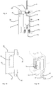
- FIG. 5 shows a schematic representation of a device according to the invention.
- a Blasformitatiteil 6b is arranged rigidly relative to the support 2 and on this Blasformangoteil 6b, the blow molding 4b is arranged.
- the first Blasformitatiteil 6a is pivotally mounted by means of the pivot shaft 82 to open in this way, the blow mold and close. Again, a part of the locking mechanism 62 is again shown schematically.
- a parting plane Te of the two blow mold parts 4a, 4b is arranged here at an angle ⁇ with respect to a radial direction R of the carrier.
- the direction of movement of the blowing stations 8 in a working operation of the device is indicated by the reference UR.
- FIG. 6 shows a further illustration for illustrating the device according to the invention.
- a holding body 90 is provided, on which the individual blow molding stations are arranged.
- This holding body 90 has an opening 92 through which a portion of the pivot shaft 82 extends.
- This holding body 90 is removable from the carrier 2. After removal of the holding body can be removed here in its entirety with 8 designated blowing station upwards from the carrier. Thus, here the blowing station 8 can be removed by movement along the arrow Y from the carrier.
- the pivot shaft 82 is pivotally mounted relative to the wall 2c and advantageously also supported by means (not shown) storage facilities. Furthermore, it is possible that a seal (not shown) is provided to seal the movement of the pivot shaft 82 relative to the carrier 2.
- a device which may for example also be arranged on the transformation arrangement, and which raises the complete blowing stations 8 including the holding body or the plate 90 upwards.
- a device can lower the blowing station on a caddy.
- FIG. 7 shows a detailed representation of a device according to the invention.
- the holding body 90 is shown, which is fastened for example by means of screw connections 91 (shown only schematically) to the carrier 2 or the bottom part 2a of the carrier 2.
- the reference numeral 97 denotes a sealing device which serves to seal the holding body or the plate 90 relative to the carrier 2 more precisely the wall 2c.
- This sealing device could be, for example, an O-ring or the like.
- a correspondingly designed plate 90 could alternatively or additionally also be provided in the upper wall 2a.
- the Figures 8a-8c illustrate the disassembly (and vice versa, the assembly) of a blowing station 8.
- the blowing station 8 can from its removal station (see. Fig. 8b ) are lifted up and then bolted to the carrier 2. After this is done, the lifting device or the lift can be removed and the blowing wheel, that is, the carrier 2 can continue to rotate to the next station, which can then also be removed or installed above.
- the blowing station is already mounted on the carrier.
- the reference numerals 102 and 104 relate to sealing devices such as bellows, with which the lifting movements, for example, a bottom part can be covered or the rotational movement of a (not shown here) locking mechanism.
- the reference numeral 110 in FIG. 8b shows a support means, which may for example also be arranged on rollers 112.
- the blowing station 8 is just through the opening 65 (see. FIG. 8b ) to either be mounted to or removed from the carrier 2.
- the plate 90, or the holding body is guided from below to the carrier and thus to the clean room and fastened by means of screws on this.
- a sealing device is provided to seal the later resulting clean room to the outside.
- the reference numeral 80 refers again to the detachable from the carrier 2 unit.
- This unit is essentially the entire blowing station with two Blasform uman former, both blow moldings and a bottom part of the blow mold.
- the unit 80 is preferably the entire blowing station with all the associated components that are needed in particular for opening and closing the blow mold.
- FIG. 9 shows a sectional view of a blowing station according to the invention 8.
- a blow molded part 4b is shown, within which the plastic preform 10 is expanded to the plastic container.
- the stretch rod 5 is shown and a channel 115, on the outside of a medium such as sterile air for expanding the
- the reference numeral 4c denotes a bottom part, which closes the blow molds in their entirety also from below. On a support 118, the bottom part is arranged and can be brought up to the blow mold.
- the sealing device 102 is shown, which is a bellows here. In this way it is also possible to arrange drive means for the carrier 118 outside of the clean room 20.
- the reference numeral 116 denotes a further sealing device, which is also designed here as a bellows and which serves to seal the movement of the loading device or blowing nozzle.
- FIG. 10 shows a further embodiment, in which case again the pivot shaft 82 can be seen with a blow mold part 4a arranged thereon.
- FIG. 11 The representation shown also shows the pivot shaft 82 and the lever assembly 66, 67, 68 with which the blow molding 4a is pivoted.
- FIG. 12 shows a further embodiment of an apparatus for forming plastic preforms to plastic containers.
- a blow molded part 4b is preferably fixed or rigidly arranged on a holding device 99.
- This holding device can be welded, for example, to the carrier 2 or even be formed integrally therewith.
- the holding device 99 it would also be conceivable for the holding device 99 to be fixedly attached to the holding body 90 (not shown) (cf. Fig. 8c ) is arranged and is removable together with this of the carrier 2.
- the embodiment shown is preferably without a Blasformitatiteil 6b, as shown above, from.
- the holding device 99 also acts as Blasformitatiteil.
- a locking mechanism for locking the blow-molded parts (not shown) can engage here, for example, in the holding device 99.
- the holding device 99 here furthermore has a stiffening effect on the carrier 2.
- Fig. 13 shows a further embodiment of an apparatus for forming plastic preforms to plastic containers.
- the blow molding 4b is disposed on a Blasformitatiteil 6b and this Blasformitatiteil 6b in turn via bolts 122 and 124 on the support.
- the Blasformitatiteil a pressurizable with a gaseous medium pressure pad.
- a pressure pad could be provided between the holding device 99 and the blow-molded part 4a.
- the bolts 122 and 124 could also be formed on the holding body 90, which preferably has a circular cross-section.
Landscapes
- Engineering & Computer Science (AREA)
- Mechanical Engineering (AREA)
- Manufacturing & Machinery (AREA)
- Blow-Moulding Or Thermoforming Of Plastics Or The Like (AREA)
- Moulds For Moulding Plastics Or The Like (AREA)
Applications Claiming Priority (1)
| Application Number | Priority Date | Filing Date | Title |
|---|---|---|---|
| DE102011053577A DE102011053577A1 (de) | 2011-09-13 | 2011-09-13 | Blasmaschine mit demontierbaren Blasstationen |
Publications (3)
| Publication Number | Publication Date |
|---|---|
| EP2570251A2 EP2570251A2 (de) | 2013-03-20 |
| EP2570251A3 EP2570251A3 (de) | 2014-10-08 |
| EP2570251B1 true EP2570251B1 (de) | 2019-10-30 |
Family
ID=46826370
Family Applications (1)
| Application Number | Title | Priority Date | Filing Date |
|---|---|---|---|
| EP12184118.3A Active EP2570251B1 (de) | 2011-09-13 | 2012-09-12 | Blasmaschine mit demontierbaren Blasstationen und Verfahren zum Demontieren von Blasstationen |
Country Status (5)
| Country | Link |
|---|---|
| US (1) | US8944794B2 (zh) |
| EP (1) | EP2570251B1 (zh) |
| JP (1) | JP6026183B2 (zh) |
| CN (1) | CN102990910B (zh) |
| DE (1) | DE102011053577A1 (zh) |
Families Citing this family (6)
| Publication number | Priority date | Publication date | Assignee | Title |
|---|---|---|---|---|
| US9067254B2 (en) * | 2008-10-16 | 2015-06-30 | The Coca-Cola Company | Method of configuring a production line to mass customize shaped vessels |
| DE102012108978A1 (de) * | 2012-09-24 | 2014-03-27 | Krones Ag | Verfahren zum Herstellen von Getränkebehältnissen und zum Auswechseln von Blasformteilen |
| CN103171141B (zh) | 2013-03-19 | 2015-08-26 | 江苏新美星包装机械股份有限公司 | 一种底模的升降机构 |
| DE202013008055U1 (de) * | 2013-09-12 | 2013-10-04 | Krones Ag | Vorrichtung zum Umformen von Kunststoffvorformlingen mit Reinraum |
| DE102013113077A1 (de) * | 2013-11-26 | 2015-05-28 | Krones Ag | Blasformmaschine mit Blasformwechselroboter mit zusätzlicher Behandlungsfunktion |
| DE102022129056A1 (de) | 2022-11-03 | 2024-05-08 | Khs Gmbh | Halterung zur Lagerung von Formteilen einer mehrteiligen Blasform, Blasformmagazin mit einer Halterung, Verfahren zum Lagern und/oder Bereitstellen von Formteilen einer mehrteiligen Blasform |
Family Cites Families (15)
| Publication number | Priority date | Publication date | Assignee | Title |
|---|---|---|---|---|
| EP1233858B1 (de) * | 1999-11-11 | 2003-11-26 | MAUSER-WERKE GmbH & Co. KG | Blasformmaschine mit elektromotorischem direktantrieb für öffnungs und schliessbewegung sowie der verriegelungsbewegung |
| FR2856334B1 (fr) * | 2003-06-19 | 2005-08-26 | Sidel Sa | Dispositif de moulage pour la fabrication de recipients en materiau thermoplastique |
| US7335007B2 (en) * | 2005-04-18 | 2008-02-26 | Graham Packaging Company, L.P. | Quick change mold |
| DE102008004773B4 (de) * | 2008-01-16 | 2022-03-10 | Krones Aktiengesellschaft | Verfahren zum Umrüsten einer Blasmaschine |
| DE102008038141A1 (de) | 2008-08-18 | 2010-02-25 | Krones Ag | Vorrichtung zum Umformen von Kunststoffvorformlingen mit Sterilraum |
| DE102009015519A1 (de) * | 2009-04-02 | 2010-10-07 | Krones Ag | Vorrichtung zum Umformen von Kunststoffvorformlingen mit Heizeinrichtung |
| DE102009039696A1 (de) * | 2009-09-02 | 2011-03-24 | Krones Ag | Vorrichtung zum Umformen von Kunststoffbehältnissen mit einer Blasform |
| DE202009018781U1 (de) * | 2009-09-02 | 2013-07-08 | Krones Ag | Vorrichtung zur Montage und/oder Demontage von Blasformen |
| DE102009040978A1 (de) * | 2009-09-11 | 2011-03-17 | Krones Ag | Magazinvorrichtung für Blasformen mit Reinigungseinrichtung |
| DE102009041160B4 (de) * | 2009-09-14 | 2018-02-22 | Krones Aktiengesellschaft | Vorrichtung zum Herstellen von Flüssigkeitsbehältnissen |
| FR2954207B1 (fr) * | 2009-12-21 | 2013-09-27 | Sidel Participations | Machine pour la fabrication de recipients comportant un systeme d'assistance au changement de moule |
| US8454342B2 (en) * | 2010-10-06 | 2013-06-04 | Graham Engineering Corporation | Modular clamp station |
| DE102011013126A1 (de) * | 2011-03-04 | 2012-09-06 | Krones Aktiengesellschaft | Blasmaschine mit Blasformverriegelung im Reinraum |
| DE102011013121A1 (de) * | 2011-03-04 | 2012-09-20 | Krones Aktiengesellschaft | Blasformmaschine mit Sterilraum und Beheizung |
| DE102011052574A1 (de) * | 2011-08-11 | 2013-02-14 | Krones Aktiengesellschaft | Blasmaschine, Verfahren zum Austauschen von Blasstationskomponenten sowie Getränkeabfüllanlage und/oder Getränkebehälterherstellanlage |
-
2011
- 2011-09-13 DE DE102011053577A patent/DE102011053577A1/de not_active Ceased
-
2012
- 2012-09-04 JP JP2012194241A patent/JP6026183B2/ja active Active
- 2012-09-05 US US13/604,473 patent/US8944794B2/en active Active
- 2012-09-12 EP EP12184118.3A patent/EP2570251B1/de active Active
- 2012-09-13 CN CN201210340235.6A patent/CN102990910B/zh active Active
Also Published As
| Publication number | Publication date |
|---|---|
| JP2013060010A (ja) | 2013-04-04 |
| CN102990910B (zh) | 2015-02-18 |
| US20130064920A1 (en) | 2013-03-14 |
| US8944794B2 (en) | 2015-02-03 |
| CN102990910A (zh) | 2013-03-27 |
| DE102011053577A1 (de) | 2013-03-14 |
| EP2570251A2 (de) | 2013-03-20 |
| JP6026183B2 (ja) | 2016-11-16 |
| EP2570251A3 (de) | 2014-10-08 |
Similar Documents
| Publication | Publication Date | Title |
|---|---|---|
| EP2495086B1 (de) | Blasmaschine mit Blasformverriegelung im Reinraum | |
| EP2570251B1 (de) | Blasmaschine mit demontierbaren Blasstationen und Verfahren zum Demontieren von Blasstationen | |
| EP2511070B1 (de) | Vorrichtung und Verfahren zum Umformen von Kunststoffvorformlingen zu Kunststoffbehältnissen mit gekoppelten Schwenk- und Verriegelungsbewegungen | |
| EP2540473B1 (de) | Vorrichtung und Verfahren zum Umformen von Kunststoffvorformlingen zu Kunststoffbehältnissen mit durch Rollmembran abgedichteter Reckstangenbewegung | |
| EP2559545B1 (de) | Vorrichtung sowie Verfahren zum Blasformen von Kunststoffvorformlingen zu Kunststoffbehältnissen mit Druckkissen | |
| EP2537662B1 (de) | Vorrichtung und Verfahren zum Umformen von Kunststoffvorformlingen zu Kunststoffbehältnissen mit abgedichteter Reckstangenbewegung | |
| EP2522485B1 (de) | Aseptische Blasformmaschine sowie -verfahren und Blasform mit steriler Luftabführung | |
| EP2848384B1 (de) | Vorrichtung zum Umformen von Kunststoffvorformlingen mit Reinraum | |
| EP2709820B1 (de) | Verfahren sowie vorrichtung zum herstellen von gefüllten behältern aus vorformlingen | |
| EP2535167B1 (de) | Blasformmaschine mit gleitlagergeführten schwenkwellen | |
| EP2537663B1 (de) | Vorrichtung und Verfahren zum Umformen von Kunststoffvorformlingen zu Kunststoffbehältnissen mit durch ein Wasserschloss geführter Luftabsaugung | |
| EP1074344B1 (de) | Vorrichtung zu Reinigung von Vulkanisationsformen | |
| EP2495090B1 (de) | Blasmaschine mit Sterilraum und Medienzuführung in dem Sterilraum | |
| EP3792036B1 (de) | Vorrichtung zum herstellen eines behälters aus einem thermoplastischen vorformling | |
| EP2832523B1 (de) | Sterile Blasformmaschine und Verfahren | |
| EP2559544B1 (de) | Vorrichtung und Verfahren zum Umformen von Kunststoffvorformlingen zu Kunststoffbehältnissen mit Druckkissen | |
| EP2848386B1 (de) | Vorrichtung zum Umformen von Kunststoffvorformlingen zu Kunststoffbehältnissen sowie Blasformträger | |
| WO2018224479A1 (de) | Blasformanordnung zum umformen von kunststoffvorformlingen zu kunststoffbehältnissen mit kraftableitungselementen und verfahren hierzu sowie vorrichtung zum umformen von kunststoffvorformlingen mit verriegelungseinrichtung | |
| EP2913174A1 (de) | Blasformmaschine mit Zentrierung des Blasformbodens | |
| EP2987618A1 (de) | Formfüllmaschine und Verfahren zum formen und Füllen von Behältern | |
| DE102013022281A1 (de) | Sterile Blasformmaschine | |
| DE202013008081U1 (de) | Vorrichtung zum Umformen von Kunststoffvorformlingen zu Kunststoffbehältnissen sowie Blasformträger |
Legal Events
| Date | Code | Title | Description |
|---|---|---|---|
| PUAI | Public reference made under article 153(3) epc to a published international application that has entered the european phase |
Free format text: ORIGINAL CODE: 0009012 |
|
| AK | Designated contracting states |
Kind code of ref document: A2 Designated state(s): AL AT BE BG CH CY CZ DE DK EE ES FI FR GB GR HR HU IE IS IT LI LT LU LV MC MK MT NL NO PL PT RO RS SE SI SK SM TR |
|
| AX | Request for extension of the european patent |
Extension state: BA ME |
|
| PUAL | Search report despatched |
Free format text: ORIGINAL CODE: 0009013 |
|
| AK | Designated contracting states |
Kind code of ref document: A3 Designated state(s): AL AT BE BG CH CY CZ DE DK EE ES FI FR GB GR HR HU IE IS IT LI LT LU LV MC MK MT NL NO PL PT RO RS SE SI SK SM TR |
|
| AX | Request for extension of the european patent |
Extension state: BA ME |
|
| RIC1 | Information provided on ipc code assigned before grant |
Ipc: B29C 49/36 20060101ALN20140901BHEP Ipc: B29C 49/42 20060101AFI20140901BHEP Ipc: B29C 49/48 20060101ALN20140901BHEP Ipc: B29C 49/46 20060101ALN20140901BHEP Ipc: B29C 33/30 20060101ALI20140901BHEP |
|
| 17P | Request for examination filed |
Effective date: 20150408 |
|
| RBV | Designated contracting states (corrected) |
Designated state(s): AL AT BE BG CH CY CZ DE DK EE ES FI FR GB GR HR HU IE IS IT LI LT LU LV MC MK MT NL NO PL PT RO RS SE SI SK SM TR |
|
| STAA | Information on the status of an ep patent application or granted ep patent |
Free format text: STATUS: EXAMINATION IS IN PROGRESS |
|
| 17Q | First examination report despatched |
Effective date: 20170623 |
|
| RIC1 | Information provided on ipc code assigned before grant |
Ipc: B29C 49/42 20060101AFI20190418BHEP Ipc: B29C 49/36 20060101ALN20190418BHEP Ipc: B29C 49/46 20060101ALN20190418BHEP Ipc: B29C 49/48 20060101ALN20190418BHEP Ipc: B29C 33/30 20060101ALI20190418BHEP |
|
| GRAP | Despatch of communication of intention to grant a patent |
Free format text: ORIGINAL CODE: EPIDOSNIGR1 |
|
| STAA | Information on the status of an ep patent application or granted ep patent |
Free format text: STATUS: GRANT OF PATENT IS INTENDED |
|
| INTG | Intention to grant announced |
Effective date: 20190527 |
|
| GRAS | Grant fee paid |
Free format text: ORIGINAL CODE: EPIDOSNIGR3 |
|
| GRAA | (expected) grant |
Free format text: ORIGINAL CODE: 0009210 |
|
| STAA | Information on the status of an ep patent application or granted ep patent |
Free format text: STATUS: THE PATENT HAS BEEN GRANTED |
|
| AK | Designated contracting states |
Kind code of ref document: B1 Designated state(s): AL AT BE BG CH CY CZ DE DK EE ES FI FR GB GR HR HU IE IS IT LI LT LU LV MC MK MT NL NO PL PT RO RS SE SI SK SM TR |
|
| REG | Reference to a national code |
Ref country code: GB Ref legal event code: FG4D Free format text: NOT ENGLISH |
|
| REG | Reference to a national code |
Ref country code: CH Ref legal event code: EP |
|
| REG | Reference to a national code |
Ref country code: AT Ref legal event code: REF Ref document number: 1195666 Country of ref document: AT Kind code of ref document: T Effective date: 20191115 |
|
| REG | Reference to a national code |
Ref country code: DE Ref legal event code: R096 Ref document number: 502012015448 Country of ref document: DE |
|
| REG | Reference to a national code |
Ref country code: IE Ref legal event code: FG4D Free format text: LANGUAGE OF EP DOCUMENT: GERMAN |
|
| REG | Reference to a national code |
Ref country code: LT Ref legal event code: MG4D |
|
| PG25 | Lapsed in a contracting state [announced via postgrant information from national office to epo] |
Ref country code: PT Free format text: LAPSE BECAUSE OF FAILURE TO SUBMIT A TRANSLATION OF THE DESCRIPTION OR TO PAY THE FEE WITHIN THE PRESCRIBED TIME-LIMIT Effective date: 20200302 Ref country code: ES Free format text: LAPSE BECAUSE OF FAILURE TO SUBMIT A TRANSLATION OF THE DESCRIPTION OR TO PAY THE FEE WITHIN THE PRESCRIBED TIME-LIMIT Effective date: 20191030 Ref country code: NL Free format text: LAPSE BECAUSE OF FAILURE TO SUBMIT A TRANSLATION OF THE DESCRIPTION OR TO PAY THE FEE WITHIN THE PRESCRIBED TIME-LIMIT Effective date: 20191030 Ref country code: NO Free format text: LAPSE BECAUSE OF FAILURE TO SUBMIT A TRANSLATION OF THE DESCRIPTION OR TO PAY THE FEE WITHIN THE PRESCRIBED TIME-LIMIT Effective date: 20200130 Ref country code: GR Free format text: LAPSE BECAUSE OF FAILURE TO SUBMIT A TRANSLATION OF THE DESCRIPTION OR TO PAY THE FEE WITHIN THE PRESCRIBED TIME-LIMIT Effective date: 20200131 Ref country code: BG Free format text: LAPSE BECAUSE OF FAILURE TO SUBMIT A TRANSLATION OF THE DESCRIPTION OR TO PAY THE FEE WITHIN THE PRESCRIBED TIME-LIMIT Effective date: 20200130 Ref country code: PL Free format text: LAPSE BECAUSE OF FAILURE TO SUBMIT A TRANSLATION OF THE DESCRIPTION OR TO PAY THE FEE WITHIN THE PRESCRIBED TIME-LIMIT Effective date: 20191030 Ref country code: LT Free format text: LAPSE BECAUSE OF FAILURE TO SUBMIT A TRANSLATION OF THE DESCRIPTION OR TO PAY THE FEE WITHIN THE PRESCRIBED TIME-LIMIT Effective date: 20191030 Ref country code: FI Free format text: LAPSE BECAUSE OF FAILURE TO SUBMIT A TRANSLATION OF THE DESCRIPTION OR TO PAY THE FEE WITHIN THE PRESCRIBED TIME-LIMIT Effective date: 20191030 Ref country code: LV Free format text: LAPSE BECAUSE OF FAILURE TO SUBMIT A TRANSLATION OF THE DESCRIPTION OR TO PAY THE FEE WITHIN THE PRESCRIBED TIME-LIMIT Effective date: 20191030 Ref country code: SE Free format text: LAPSE BECAUSE OF FAILURE TO SUBMIT A TRANSLATION OF THE DESCRIPTION OR TO PAY THE FEE WITHIN THE PRESCRIBED TIME-LIMIT Effective date: 20191030 |
|
| REG | Reference to a national code |
Ref country code: NL Ref legal event code: MP Effective date: 20191030 |
|
| PG25 | Lapsed in a contracting state [announced via postgrant information from national office to epo] |
Ref country code: HR Free format text: LAPSE BECAUSE OF FAILURE TO SUBMIT A TRANSLATION OF THE DESCRIPTION OR TO PAY THE FEE WITHIN THE PRESCRIBED TIME-LIMIT Effective date: 20191030 Ref country code: RS Free format text: LAPSE BECAUSE OF FAILURE TO SUBMIT A TRANSLATION OF THE DESCRIPTION OR TO PAY THE FEE WITHIN THE PRESCRIBED TIME-LIMIT Effective date: 20191030 Ref country code: IS Free format text: LAPSE BECAUSE OF FAILURE TO SUBMIT A TRANSLATION OF THE DESCRIPTION OR TO PAY THE FEE WITHIN THE PRESCRIBED TIME-LIMIT Effective date: 20200229 |
|
| PG25 | Lapsed in a contracting state [announced via postgrant information from national office to epo] |
Ref country code: AL Free format text: LAPSE BECAUSE OF FAILURE TO SUBMIT A TRANSLATION OF THE DESCRIPTION OR TO PAY THE FEE WITHIN THE PRESCRIBED TIME-LIMIT Effective date: 20191030 |
|
| PG25 | Lapsed in a contracting state [announced via postgrant information from national office to epo] |
Ref country code: RO Free format text: LAPSE BECAUSE OF FAILURE TO SUBMIT A TRANSLATION OF THE DESCRIPTION OR TO PAY THE FEE WITHIN THE PRESCRIBED TIME-LIMIT Effective date: 20191030 Ref country code: CZ Free format text: LAPSE BECAUSE OF FAILURE TO SUBMIT A TRANSLATION OF THE DESCRIPTION OR TO PAY THE FEE WITHIN THE PRESCRIBED TIME-LIMIT Effective date: 20191030 Ref country code: DK Free format text: LAPSE BECAUSE OF FAILURE TO SUBMIT A TRANSLATION OF THE DESCRIPTION OR TO PAY THE FEE WITHIN THE PRESCRIBED TIME-LIMIT Effective date: 20191030 Ref country code: EE Free format text: LAPSE BECAUSE OF FAILURE TO SUBMIT A TRANSLATION OF THE DESCRIPTION OR TO PAY THE FEE WITHIN THE PRESCRIBED TIME-LIMIT Effective date: 20191030 |
|
| REG | Reference to a national code |
Ref country code: DE Ref legal event code: R097 Ref document number: 502012015448 Country of ref document: DE |
|
| PG25 | Lapsed in a contracting state [announced via postgrant information from national office to epo] |
Ref country code: SM Free format text: LAPSE BECAUSE OF FAILURE TO SUBMIT A TRANSLATION OF THE DESCRIPTION OR TO PAY THE FEE WITHIN THE PRESCRIBED TIME-LIMIT Effective date: 20191030 Ref country code: SK Free format text: LAPSE BECAUSE OF FAILURE TO SUBMIT A TRANSLATION OF THE DESCRIPTION OR TO PAY THE FEE WITHIN THE PRESCRIBED TIME-LIMIT Effective date: 20191030 |
|
| PLBE | No opposition filed within time limit |
Free format text: ORIGINAL CODE: 0009261 |
|
| STAA | Information on the status of an ep patent application or granted ep patent |
Free format text: STATUS: NO OPPOSITION FILED WITHIN TIME LIMIT |
|
| 26N | No opposition filed |
Effective date: 20200731 |
|
| PG25 | Lapsed in a contracting state [announced via postgrant information from national office to epo] |
Ref country code: SI Free format text: LAPSE BECAUSE OF FAILURE TO SUBMIT A TRANSLATION OF THE DESCRIPTION OR TO PAY THE FEE WITHIN THE PRESCRIBED TIME-LIMIT Effective date: 20191030 |
|
| PG25 | Lapsed in a contracting state [announced via postgrant information from national office to epo] |
Ref country code: MC Free format text: LAPSE BECAUSE OF FAILURE TO SUBMIT A TRANSLATION OF THE DESCRIPTION OR TO PAY THE FEE WITHIN THE PRESCRIBED TIME-LIMIT Effective date: 20191030 |
|
| REG | Reference to a national code |
Ref country code: CH Ref legal event code: PL |
|
| GBPC | Gb: european patent ceased through non-payment of renewal fee |
Effective date: 20200912 |
|
| REG | Reference to a national code |
Ref country code: BE Ref legal event code: MM Effective date: 20200930 |
|
| PG25 | Lapsed in a contracting state [announced via postgrant information from national office to epo] |
Ref country code: LU Free format text: LAPSE BECAUSE OF NON-PAYMENT OF DUE FEES Effective date: 20200912 |
|
| PG25 | Lapsed in a contracting state [announced via postgrant information from national office to epo] |
Ref country code: LI Free format text: LAPSE BECAUSE OF NON-PAYMENT OF DUE FEES Effective date: 20200930 Ref country code: IE Free format text: LAPSE BECAUSE OF NON-PAYMENT OF DUE FEES Effective date: 20200912 Ref country code: GB Free format text: LAPSE BECAUSE OF NON-PAYMENT OF DUE FEES Effective date: 20200912 Ref country code: CH Free format text: LAPSE BECAUSE OF NON-PAYMENT OF DUE FEES Effective date: 20200930 Ref country code: BE Free format text: LAPSE BECAUSE OF NON-PAYMENT OF DUE FEES Effective date: 20200930 |
|
| REG | Reference to a national code |
Ref country code: AT Ref legal event code: MM01 Ref document number: 1195666 Country of ref document: AT Kind code of ref document: T Effective date: 20200912 |
|
| PG25 | Lapsed in a contracting state [announced via postgrant information from national office to epo] |
Ref country code: AT Free format text: LAPSE BECAUSE OF NON-PAYMENT OF DUE FEES Effective date: 20200912 |
|
| PG25 | Lapsed in a contracting state [announced via postgrant information from national office to epo] |
Ref country code: TR Free format text: LAPSE BECAUSE OF FAILURE TO SUBMIT A TRANSLATION OF THE DESCRIPTION OR TO PAY THE FEE WITHIN THE PRESCRIBED TIME-LIMIT Effective date: 20191030 Ref country code: MT Free format text: LAPSE BECAUSE OF FAILURE TO SUBMIT A TRANSLATION OF THE DESCRIPTION OR TO PAY THE FEE WITHIN THE PRESCRIBED TIME-LIMIT Effective date: 20191030 Ref country code: CY Free format text: LAPSE BECAUSE OF FAILURE TO SUBMIT A TRANSLATION OF THE DESCRIPTION OR TO PAY THE FEE WITHIN THE PRESCRIBED TIME-LIMIT Effective date: 20191030 |
|
| PG25 | Lapsed in a contracting state [announced via postgrant information from national office to epo] |
Ref country code: MK Free format text: LAPSE BECAUSE OF FAILURE TO SUBMIT A TRANSLATION OF THE DESCRIPTION OR TO PAY THE FEE WITHIN THE PRESCRIBED TIME-LIMIT Effective date: 20191030 |
|
| P01 | Opt-out of the competence of the unified patent court (upc) registered |
Effective date: 20230523 |
|
| PGFP | Annual fee paid to national office [announced via postgrant information from national office to epo] |
Ref country code: IT Payment date: 20230810 Year of fee payment: 12 |
|
| PGFP | Annual fee paid to national office [announced via postgrant information from national office to epo] |
Ref country code: FR Payment date: 20230808 Year of fee payment: 12 Ref country code: DE Payment date: 20230802 Year of fee payment: 12 |