EP2559544B1 - Vorrichtung und Verfahren zum Umformen von Kunststoffvorformlingen zu Kunststoffbehältnissen mit Druckkissen - Google Patents
Vorrichtung und Verfahren zum Umformen von Kunststoffvorformlingen zu Kunststoffbehältnissen mit Druckkissen Download PDFInfo
- Publication number
- EP2559544B1 EP2559544B1 EP12179848.2A EP12179848A EP2559544B1 EP 2559544 B1 EP2559544 B1 EP 2559544B1 EP 12179848 A EP12179848 A EP 12179848A EP 2559544 B1 EP2559544 B1 EP 2559544B1
- Authority
- EP
- European Patent Office
- Prior art keywords
- blow mould
- blow
- carrier shell
- shell part
- mould carrier
- Prior art date
- Legal status (The legal status is an assumption and is not a legal conclusion. Google has not performed a legal analysis and makes no representation as to the accuracy of the status listed.)
- Active
Links
- 229920003023 plastic Polymers 0.000 title claims description 45
- 239000004033 plastic Substances 0.000 title claims description 45
- 238000000034 method Methods 0.000 title claims description 22
- 238000002407 reforming Methods 0.000 title 1
- 238000000071 blow moulding Methods 0.000 claims description 70
- 230000009969 flowable effect Effects 0.000 claims description 15
- 238000007493 shaping process Methods 0.000 claims description 2
- 239000000463 material Substances 0.000 claims 4
- 238000007789 sealing Methods 0.000 description 26
- 230000036961 partial effect Effects 0.000 description 22
- 238000007664 blowing Methods 0.000 description 20
- 230000001954 sterilising effect Effects 0.000 description 16
- 230000008569 process Effects 0.000 description 13
- 238000004659 sterilization and disinfection Methods 0.000 description 13
- 238000012546 transfer Methods 0.000 description 8
- 230000002829 reductive effect Effects 0.000 description 6
- 239000000969 carrier Substances 0.000 description 5
- 230000000694 effects Effects 0.000 description 5
- 238000010438 heat treatment Methods 0.000 description 5
- 238000003780 insertion Methods 0.000 description 5
- 230000037431 insertion Effects 0.000 description 5
- MHAJPDPJQMAIIY-UHFFFAOYSA-N Hydrogen peroxide Chemical compound OO MHAJPDPJQMAIIY-UHFFFAOYSA-N 0.000 description 4
- 210000000078 claw Anatomy 0.000 description 3
- 238000013461 design Methods 0.000 description 3
- 239000000725 suspension Substances 0.000 description 3
- 238000005496 tempering Methods 0.000 description 3
- 230000008859 change Effects 0.000 description 2
- 238000006243 chemical reaction Methods 0.000 description 2
- 239000007789 gas Substances 0.000 description 2
- 238000004519 manufacturing process Methods 0.000 description 2
- 230000002093 peripheral effect Effects 0.000 description 2
- 238000003825 pressing Methods 0.000 description 2
- 238000000926 separation method Methods 0.000 description 2
- 230000009466 transformation Effects 0.000 description 2
- 238000007792 addition Methods 0.000 description 1
- 238000013459 approach Methods 0.000 description 1
- 235000013361 beverage Nutrition 0.000 description 1
- 230000015572 biosynthetic process Effects 0.000 description 1
- 239000003795 chemical substances by application Substances 0.000 description 1
- 230000008878 coupling Effects 0.000 description 1
- 238000010168 coupling process Methods 0.000 description 1
- 238000005859 coupling reaction Methods 0.000 description 1
- 230000001419 dependent effect Effects 0.000 description 1
- 238000011161 development Methods 0.000 description 1
- 230000018109 developmental process Effects 0.000 description 1
- 238000006073 displacement reaction Methods 0.000 description 1
- 229920001971 elastomer Polymers 0.000 description 1
- 239000000806 elastomer Substances 0.000 description 1
- 230000005670 electromagnetic radiation Effects 0.000 description 1
- 239000004744 fabric Substances 0.000 description 1
- 230000002349 favourable effect Effects 0.000 description 1
- 210000000569 greater omentum Anatomy 0.000 description 1
- 230000036512 infertility Effects 0.000 description 1
- 239000012212 insulator Substances 0.000 description 1
- 230000003993 interaction Effects 0.000 description 1
- 230000000670 limiting effect Effects 0.000 description 1
- 239000007788 liquid Substances 0.000 description 1
- 230000014759 maintenance of location Effects 0.000 description 1
- ORQBXQOJMQIAOY-UHFFFAOYSA-N nobelium Chemical compound [No] ORQBXQOJMQIAOY-UHFFFAOYSA-N 0.000 description 1
- 230000001681 protective effect Effects 0.000 description 1
- 230000002441 reversible effect Effects 0.000 description 1
- 239000007787 solid Substances 0.000 description 1
- 239000003206 sterilizing agent Substances 0.000 description 1
- 238000009423 ventilation Methods 0.000 description 1
- XLYOFNOQVPJJNP-UHFFFAOYSA-N water Substances O XLYOFNOQVPJJNP-UHFFFAOYSA-N 0.000 description 1
Images


Classifications
-
- B—PERFORMING OPERATIONS; TRANSPORTING
- B29—WORKING OF PLASTICS; WORKING OF SUBSTANCES IN A PLASTIC STATE IN GENERAL
- B29D—PRODUCING PARTICULAR ARTICLES FROM PLASTICS OR FROM SUBSTANCES IN A PLASTIC STATE
- B29D22/00—Producing hollow articles
- B29D22/003—Containers for packaging, storing or transporting, e.g. bottles, jars, cans, barrels, tanks
-
- B—PERFORMING OPERATIONS; TRANSPORTING
- B29—WORKING OF PLASTICS; WORKING OF SUBSTANCES IN A PLASTIC STATE IN GENERAL
- B29C—SHAPING OR JOINING OF PLASTICS; SHAPING OF MATERIAL IN A PLASTIC STATE, NOT OTHERWISE PROVIDED FOR; AFTER-TREATMENT OF THE SHAPED PRODUCTS, e.g. REPAIRING
- B29C49/00—Blow-moulding, i.e. blowing a preform or parison to a desired shape within a mould; Apparatus therefor
- B29C49/42—Component parts, details or accessories; Auxiliary operations
- B29C49/48—Moulds
- B29C2049/4856—Mounting, exchanging or centering moulds or parts thereof
- B29C2049/4864—Fixed by a special construction to the mould half carriers, e.g. using insulating material between the mould and the mould half carrier
-
- B—PERFORMING OPERATIONS; TRANSPORTING
- B29—WORKING OF PLASTICS; WORKING OF SUBSTANCES IN A PLASTIC STATE IN GENERAL
- B29C—SHAPING OR JOINING OF PLASTICS; SHAPING OF MATERIAL IN A PLASTIC STATE, NOT OTHERWISE PROVIDED FOR; AFTER-TREATMENT OF THE SHAPED PRODUCTS, e.g. REPAIRING
- B29C2949/00—Indexing scheme relating to blow-moulding
- B29C2949/07—Preforms or parisons characterised by their configuration
- B29C2949/0715—Preforms or parisons characterised by their configuration the preform having one end closed
-
- B—PERFORMING OPERATIONS; TRANSPORTING
- B29—WORKING OF PLASTICS; WORKING OF SUBSTANCES IN A PLASTIC STATE IN GENERAL
- B29C—SHAPING OR JOINING OF PLASTICS; SHAPING OF MATERIAL IN A PLASTIC STATE, NOT OTHERWISE PROVIDED FOR; AFTER-TREATMENT OF THE SHAPED PRODUCTS, e.g. REPAIRING
- B29C33/00—Moulds or cores; Details thereof or accessories therefor
- B29C33/30—Mounting, exchanging or centering
-
- B—PERFORMING OPERATIONS; TRANSPORTING
- B29—WORKING OF PLASTICS; WORKING OF SUBSTANCES IN A PLASTIC STATE IN GENERAL
- B29C—SHAPING OR JOINING OF PLASTICS; SHAPING OF MATERIAL IN A PLASTIC STATE, NOT OTHERWISE PROVIDED FOR; AFTER-TREATMENT OF THE SHAPED PRODUCTS, e.g. REPAIRING
- B29C49/00—Blow-moulding, i.e. blowing a preform or parison to a desired shape within a mould; Apparatus therefor
- B29C49/02—Combined blow-moulding and manufacture of the preform or the parison
- B29C49/06—Injection blow-moulding
-
- B—PERFORMING OPERATIONS; TRANSPORTING
- B29—WORKING OF PLASTICS; WORKING OF SUBSTANCES IN A PLASTIC STATE IN GENERAL
- B29C—SHAPING OR JOINING OF PLASTICS; SHAPING OF MATERIAL IN A PLASTIC STATE, NOT OTHERWISE PROVIDED FOR; AFTER-TREATMENT OF THE SHAPED PRODUCTS, e.g. REPAIRING
- B29C49/00—Blow-moulding, i.e. blowing a preform or parison to a desired shape within a mould; Apparatus therefor
- B29C49/28—Blow-moulding apparatus
- B29C49/30—Blow-moulding apparatus having movable moulds or mould parts
- B29C49/36—Blow-moulding apparatus having movable moulds or mould parts rotatable about one axis
Definitions
- the present invention relates to an apparatus and a method for forming plastic preforms into plastic containers.
- Such devices and methods have been known for a long time from the prior art.
- blow molds or blow moldings are arranged on carriers and these carriers can be unfolded and folded, wherein in a closed state of the blow mold plastic preforms are expanded inside this blow mold, in particular by application of compressed air to plastic containers.
- two mold carrier shells are provided, on each of which the blow-molded parts are fixed. These mold carrier shells are in turn arranged on a blow mold carrier or a blow mold carrier part.
- the document US-A-2004202745 discloses an apparatus and a method according to the preambles of claims 1 and 7.
- Increasing production figures are important parameters, in particular for the customers of the equipment in question here.
- the present invention is therefore based on the object of reducing downtimes, in particular downtimes due to changes of cloth.
- Another object of the present invention is to provide a quick-change system which can be operated without an additional tool.
- Another object is to achieve a simple and quick handling, without the need for a manual operation of locks is required.
- An inventive device for forming plastic preforms to plastic containers is disclosed by the claim 1.
- the holding device has an actuating body which extends through an opening formed in a wall of the blow mold carrier shell part and / or an opening formed in a wall of a blow mold carrier part, this actuating body being movable relative to the wall and wherein a first holding element for holding the blow molded part is arranged on the actuating body is.
- the actuating body or at least a portion of this actuating body extends through the wall of the Blasformitatischalenteils and / or the wall of Blasformziteils through.
- the actuating body or at least a portion of this actuating body extends through the wall of the Blasformitatischalenteils and / or the wall of Blasformziteils through.
- the actuating body or at least a portion of this actuating body extends through the wall of the Blasformitatis through.
- a corresponding (for example pneumatically) actuated actuating system is therefore advantageously integrated in this system essentially completely in the blow mold carrier shell.
- a connection for example a pneumatic connection, can be installed directly over the blow mold carrier shell part in an advantageous blow mold carrier shell part in the mold carrier halves.
- the actuating body may be, for example, a piston element which, as mentioned above, is pneumatically movable.
- this piston or the actuator body performs the function of a clamping hook.
- the clamping hook represents a preferred embodiment of the above-mentioned holding element and advantageously takes both the task of a grid position during insertion of the blow molding and on the other hand, the task of clamping the blow molded part true.
- a connection for a flowable medium and in particular for a gaseous medium is arranged on at least one Blasformitatischalenteil.
- the actuating body on a druckstoffbeetzmacherbaren piston can be arranged in a cylinder system.
- the holding element - preferably fixed - arranged.
- the opening in the wall is arranged in a recess formed in the wall of the wall.
- This wall may extend outward in a radial direction of the closed blow mold. Through this recess, the insertion of the respective blow molding is facilitated.
- a second retaining element is fastened to the blow molding part, which acts together with the first retaining element for fastening the blow molding part to the blow mold carrier shell part.
- a grip element for example, be screwed, in which engages said first support member. Due to the interaction of these two holding elements, the blow molding is attached to the Blasformitatischalenteil.
- the second holding element is rigidly connected to the blow molding.
- the holding element arranged on the blow mold carrier shell part engages behind the holding element arranged on the blow mold part.
- the second holding element projects with respect to a wall of the blow-molded part.
- the second holding element may be arranged on a carrier, and a portion of the carrier may protrude with respect to the said wall of the blow-molded part. This projecting portion can engage in the above-mentioned recess in the wall of the Blasformitatischalenteils.
- a relative movement of the blow molding relative to the Blasformitatischalen matter only in a relaxed state of the holding device is possible, but not in a fixed or mounted state.
- this relative movement is a rotary movement of the blow molded part with respect to a predetermined axis of rotation relative to the blow mold carrier shell part.
- a holder for a blow mold carrier is also arranged on the blow mold carrier shell part.
- the present invention is further directed to a method of attaching blow moldings to blow mold carrier shell parts according to claim 7.
- the blow mold part After being applied to the blow mold carrier shell part, the blow mold part is moved relative to the blow mold carrier shell part such that a first holding element arranged on the blow mold carrier shell part and a second holding element arranged on the blow mold part engage in one another.
- the first holding element arranged on the blow mold carrier shell part is moved in a further direction in order to lock the blow molded part to the blow mold carrier shells, the movement of the first holding element being produced by an actuating body which extends at least partially through a wall of the blow mold carrier shell part.
- a pressure pad arrangement is arranged between at least one blow mold carrier part and the blow mold part arranged on this blow mold carrier, a pressure chamber or a pressure pad device of this pressure pad arrangement being able to be acted upon by a flowable pressure medium, by at least one blow mold carrier part and by a force acting between the blow mold carrier part and the blow mold part to push apart at this arranged blow molding.
- the pressure pad arrangement is formed such that the force acting between the Blasformsammlungteil and the blow molding part has a first partial force in a first predetermined - and preferably spatially definable or definable - and preferably spatially definable or delimitable - in the circumferential direction of the blow molding acts as a second partial force acting in a second predetermined range in the circumferential direction of the blow molding, wherein the first region and the second region are spaced apart and the directions of the first partial force and the second partial force in an angle different from each other by 0 degrees
- the given areas in which the partial forces act therefore, preferably result from a particular geometric shape of the pressure pad assembly.
- the arrangement of the blow molded part on the blow mold carrier part means that this blow molded part is arranged at least indirectly, ie, if necessary, for further elements on the blow mold carrier part.
- the blow molding is in turn on a Blasformitatischale, hereinafter also briefly arranged as a carrier shell and this carrier shell is preferably disposed on the Blasformangoteil, said pressure pad assembly between the Blasformitatiteil and the said carrier shell is formed.
- the prior art is usually between the Blasformitatiteil and the blow molding only one arranged uniform pressure pad, which can be acted upon with compressed air. Accordingly, when the pressure pad is acted upon, a resultant force acts only in one direction, so that in this resultant direction the blow mold and the blow mold carrier are forced apart.
- the flowable medium with which the pressure pad is acted upon is, in particular, a gaseous medium, preferably air and, if necessary, sterile air.
- the position and design of the pressure pad is designed so that the deformation in the mold carrier and in the (form) carrier shell is reduced. More specifically, the forces applied by the pressure pad are divided into at least two components that act at different angles on the carrier shell or blow mold, thereby reducing the risk of tension during the expansion process.
- the two partial forces are independent of each other and particularly preferably also - in particular with regard to their sizes - independently adjustable.
- no force acts (apart from a vekotriell from the partial forces together) force or only one compared to the partial forces significantly lower force, which forces apart the blow molded part and the Blasformangoteil.
- the device for forming plastic preforms also has a loading device, which acts on the plastic preforms during the expansion process with a gaseous medium and in particular with compressed air in order to expand them.
- the device preferably also has a stretching rod which stretches the plastic preforms in the longitudinal direction thereof during the expansion process.
- a locking device which locks the mold carrier parts together, in particular during the expansion process.
- This lock can engage cam-controlled and designed in this way be that at the beginning of the expansion process and also in the course of the expansion process, the two mold carrier parts are locked together.
- the design with the two partial forces allows a more uniform pressing of the two blow moldings together.
- the device has only such a pressure pad arrangement on one of the two mold carriers.
- the angle between the direction of the first partial force and the direction of the second partial force between 10 ° and 170 °, preferably between 20 ° and 160 °, preferably between 30 ° and 150 °, preferably between 45 ° and 135 ° , preferably between 60 ° and 120 ° and more preferably between 75 ° and 105 °.
- the pressure pad is arranged in a V-arrangement, so that the two forces are in the said angle to each other.
- the carrier shell is held on the Blasformarmeteil via a positive retention, so that a fixed position of said pressure pad is achieved.
- the pressure pad arrangement has a first pressure pad device and a second pressure pad device which are at least partially or partially separated from one another and are preferably completely separated from one another.
- said pressure pad devices By means of said pressure pad devices, the abovementioned two forces may optionally be applied to the blow mold or carrier shell independently of one another. However, it would also be possible that only a pressure pad device is provided, but this is designed such that the two forces mentioned above arise. This can be achieved, for example, by a web within a single pressure pad device, which ensures that no or only small forces are exerted in the circumferential direction of the blow mold in a central region between the two partial forces mentioned.
- An at least partial separation of the pressure pad devices is understood in particular to mean that these pressure pad devices can be connected to one another via a connecting section, but that connecting section is not along an entire side edge of at least one pressure pad device but only along a portion of such a side edge, which is preferably less than 50% of the side edge, preferably less than 30% of the side edge, preferably less than 20% of the side edge.
- the pressure pad devices are advantageously connected to one another via a connecting section which extends to less than 20% of the circumference of at least one of the two pressure pad devices, preferably to less than 10% of the circumference, preferably to less than 5% of the circumference scope.
- the apparatus has a first supply means for supplying the flowable medium to the first pressure pad means, as well as a second feeding means separate therefrom, for feeding the flowable medium to the second pressure pad means. In this way, a different control of the two pressure pad devices is possible.
- the supply channels for the two pressure pad devices can be completely separated from each other, but it would also be possible that the two pressure pad devices via a common port, the flowable medium, ie the compressed air is supplied.
- the pressure pad arrangement has an encircling sealing device, which supports the space acted upon by the flowable pressure medium, ie. H. the pressure chamber, delimits, and this sealing device abuts against a flat wall area.
- the sealing device In the prior art, three-dimensionally applied sealing devices are commonly used, i. H. in particular sealing devices, which also extend along a curved portion of the carrier shell or the blow mold or blow mold carrier. In this embodiment, it is proposed that the sealing device only along a plane d. H. a straight plane and thus extends only in the two-dimensional area. In this way, an improved sealing effect is possible.
- the pressure pad arrangement is arranged between the blow mold carrier part and a carrier shell holding the blow mold part.
- This carrier shell can be designed such that the blow molded part is detachably designed by this carrier shell.
- the device has a holding device for holding the blow molding on the Blasformanii, and this holding device is arranged in a circumferential direction of the blow mold between areas of the pressure pad assembly.
- a preferably with respect to the pressure pad assembly arrangement of the holding device is provided which, for example, if only one pressure pad device is provided, may be provided on a corresponding limiting web.
- the holding device is arranged between the first pressure pad device and the second pressure pad device.
- no force is exerted in the direction of the blow mold by the pressure pad itself.
- a blow mold which has two blow moldings arranged in a mutually moveable manner, which form a cavity in a closed state of the blow mold, in the interior of which the plastic preforms are imparted by application of a flowable plastic preform Medium and in particular be expanded with compressed air to the plastic containers.
- the first blow molding is arranged on a first Blasformitatiteil and the second blow molding on a second Blasformitatiteil.
- the first blow mold carrier part is moved relative to the second blow mold carrier part for opening and closing the blow mold.
- a pressure chamber or a pressure device of this pressure pad assembly is acted upon by a flowable pressure medium to at least by a force acting between the Blasformitatiteil and the blow molding force to force apart a blow mold carrier part and the blow mold part arranged thereon.
- the pressure pad assembly is formed such that the force acting between the blow mold carrier member and the blow molding member has a first parting force acting in a first predetermined region in the circumferential direction of the blow molding member, such as a second component force acting in a second predetermined region in the circumferential direction of Blow molding, wherein the first region and the second region are spaced apart and the directions of the first partial force and the second partial force in a 0 degrees different angle to each other.
- the pressure pad assembly is designed so that at least two partial forces are provided, which act on the blow molding or a blow molding holding carrier shell.
- a holding force acting between the blow molding part and the blow mold carrier part acts in the circumferential direction of the blow mold between the first part force and the second part force.
- FIG. 1 shows a schematic representation of a plant for producing plastic containers according to the prior art.
- This system 50 has a heating device 30 in which plastic preforms 10 are heated.
- these plastic preforms 10 are guided by means of a transport device 34, such as a revolving chain, through this heater 30 and thereby heated with a plurality of heating elements 31.
- This heating device 30 is followed by a transfer unit 36, which transfers the preforms 10 to a sterilization device 32.
- This sterilization device 32 in this case likewise has a transport wheel 37 and sterilizing elements can be arranged on this transport wheel 37 or even stationary. In this area, for example, a sterilization by hydrogen peroxide gas or by electromagnetic radiation is possible. In particular, an internal sterilization of the preforms is carried out in this area.
- the reference numeral 20 denotes in its entirety a clean room, the outer boundaries are indicated here by the dotted line L.
- the clean room 20 is arranged not only in the region of the transport wheel 2 and filling device 40, but possibly already starts in the area of the heating device 30, the sterilization device 32, the plastic preform supply and / or the plastic preform production. It can be seen that this clean room 20 begins in the area of the sterilization unit 32. In this area, lock devices can be provided to introduce the plastic preforms into the clean room 20 without too much gas flowing inside the clean room and thus being lost.
- the clean room is, as indicated by the dashed line L, adapted to the outer shape of the individual plant components. In this way, the volume of the clean room can be reduced.
- the reference numeral 1 denotes in its entirety a forming device in which a plurality of blowing stations or forming stations 8 is arranged on a transport wheel 2, wherein only one of these blowing stations 8 is shown here. With these blowing stations 8, the plastic preforms 10 are expanded to containers 10a. Although not shown in detail here, not the entire area of the transport device 2 is located within the clean room 20, but the clean room 20 or insulator is effectively implemented as a mini-isolator within the entire device. Thus, it would be possible for the clean room to be channel-like, at least in the area of the forming device 1.
- the reference numeral 22 refers to a feeding device which transfers the preforms to the forming device 1 and the reference numeral 24 to a discharge device which discharges the produced plastic containers 20 from the forming device 1. It can be seen that the clean room 20 in the area of the feed device 22 and the discharge device 24 each have recesses which receive these devices 22, 24. In this way, a transfer of the plastic preforms 10 to the forming device 1 and a takeover of the plastic containers 10a of the forming device 1 can be achieved in a particularly advantageous manner.
- the expanded plastic containers are transferred to a filling device 40 and then from this filling device 40 via a further transport unit 44 removed.
- the filling device it would also be possible for the entire filling device 40 with, for example, a reservoir for a beverage, not to be arranged completely inside the clean room 6, but here too only those areas where the containers are actually kept.
- the filling device could be constructed in a similar manner as the device 1 for forming plastic preforms 10th
- the clean room 20 in the area of the device 1 is reduced to a minimum possible area, namely substantially to the blowing stations 8 itself.
- This small-sized design of the clean room 20 makes it easier and faster to produce a clean room at all and also to maintain sterility in the operating phase is less expensive. Also, less sterile air is needed, resulting in smaller filter units and also the risk of uncontrolled vortex formation is reduced.
- FIG. 2 shows a detailed representation of the device 1 in the region of a blowing station 8.
- a plurality of such blowing stations 8 is rotatably moved with a transport device 2 and a support about an axis X.
- the blowing station 8 is as in FIG. 2 can be seen within the clean room 20, which is here channel-like out.
- This clean room 20 is completed by a movable side wall 19 and a lid 17 integrally formed with this side wall 19. This side wall 19 and the cover 17 thereby rotate with the blowing station 8.
- the reference numeral 18 refers to a further wall which limits the clean room 16.
- This wall 18 is here an outer wall, which is arranged stationary.
- a sealing device 25 is provided between the cover 17 and the wall 18, which seals the mutually movable elements 17 and 18 against each other, for example, as mentioned above, using a water lock.
- the lower portion of the wall 18 is fixedly and sealingly arranged on a bottom 13.
- a support 26 is provided, which also moves in rotation and on which in turn a holding device 23 is provided, which holds the blowing station 8.
- the reference numeral 11 refers to a follower which can be actuated by a guide cam 9 to open and close the blow station on its way through the clean room 6, in particular to insert the plastic preform in the blow station and to remove it again.
- a guide curve 9 is also arranged within the clean room 20.
- the transport device 2 may also have further elements, which are arranged above the clean room 20.
- the carrier 26 is fixedly arranged on a holding body 29 and this holding body is in turn movable relative to the bottom 13.
- the reference numeral 27 refers to a further sealing device, which causes a sealing of the mutually movable portions 13 and 29 in this area.
- the reference numeral 5 refers to a stretching rod which is movable with respect to the blowing station in order to stretch the plastic preforms 10 in their longitudinal direction.
- a carriage 12 is arranged on the lid 17, on the other hand, the stretch rod in the direction Y is movable.
- the reference numeral 21 refers to a further holder for this carriage 12 of the stretch rod. 5
- the reference symbol U denotes the (non-sterile) environment of the clean room 20.
- the reference symbol 28 designates a carrier for supporting a bottom mold, which likewise forms part of the blow mold 4. This carrier is also movable in the direction Y.
- the reference numeral 55 refers to a sterilization device, which is preferably arranged here in the interior of the clean room 20 and for sterilizing the individual transformation stations or components of these conversion stations 8 is used.
- This sterilization device 55 can act on the conversion stations 8, for example, with hydrogen peroxide or other sterilizing agent.
- the sterilization device 55 can be arranged stationary and the transformation stations can move relative to this sterilization device 55.
- This sterilization device or loading device 55 may be located on the transport wheel 2 or on the stationary wall 18 or may be arranged generally stationary and consist of nozzles o similar.
- the blow molds (not shown) are disposed inside the blow mold carriers 6. More precisely, two Blasformabomaschine can be arranged, which are pivotable relative to each other and each holding a blow mold. By this pivoting process, the blow molds for introducing plastic preforms and for removing finished blown containers can be opened. These blow mold carriers and blow molds are likewise arranged inside the clean room.
- the transport device 2 or the carrier has a C-shaped outer circumference, which also partially forms the outer walls of the clean room.
- this C - shaped clean room wall rotates here with the transport device 2, ie the blowing wheel.
- the lower boundary of the clean room is spaced from the floor 13 and moves relative to the floor. In this way, the clean room can be made even smaller than in Fig.2 shown.
- This outer wall is advantageously arranged stationary.
- the in the Figures 1 and 2 The arrangement shown relates to a sterile blow molding arrangement. However, the present invention is also applicable to conventional or non-sterile blow molding machines. Also in FIG. 1 The system concept shown can be used for both sterile and non-sterile machines.
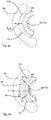
- Fig. 3a and 3b show two schematic representations to illustrate the problem underlying the invention and its solution.
- Fig. 3a shows the conditions according to the prior art
- a Blasformitatiteil 6a is provided on which a blow mold 4a (possibly. On a carrier shell) is arranged .. It would also be conceivable to attach the blow molds directly to the carrier.
- a pressure pad provided in the circumferential direction UR, which is formed between the two seal portions 182a and 182b. This pressure pad thus generates a resulting force Fres, which acts horizontally here.
- the small force arrows inside the blow molds refer to the forces that are created by the actual blowing process. This means that it can lead to tension and also to deformations of the blow mold or the Blasformitatischale in this way.
- Fig. 3b shows an embodiment of the invention.
- two pressure cushions spaced apart from each other by the circumferential seals 82, 84 are provided here, which in this case exert partial forces F1 and F2 which are arranged at the predetermined angle relative to one another on the blow mold 4a or the carrier shell for the blow mold.
- the reference numerals 82, 84 thus denote sealing devices which surround or form the two pressure pads. Due to the effect with two partial forces F1 and F2, an overall more uniform force effect can be exerted on the blow mold 4a or the carrier shell. These two areas B1 and B2 in which the partial forces act are spaced apart here in the circumferential direction UR of the blow mold.
- the angle a, under which the two forces F1 and F2 extend to each other, is advantageously in a range between 70 ° and 110 °.
- the circumferential direction is advantageously also a circumferential direction of the plastic preform or container to be expanded.
- the mentioned angle ⁇ is advantageously formed in a plane formed by the circumferential direction. This plane is advantageously perpendicular to a longitudinal direction of the plastic preform and is advantageously parallel to the plane of the figure of Fig. 3b
- FIG. 4 shows a perspective view of a blowing station according to the invention 8.
- This blow station 8 has two blow mold parts 4a, 4b, which are shown here in a closed state. Between these two blow mold parts 4a, 4b is the above-mentioned Cavity formed within which the plastic preforms are expanded to the plastic containers.
- blow molding 4a and accordingly also the blow molding 4b are here fixed to Blasformitatischaleniser 70a, 70b fixed, for example, clamped or screwed.
- These blow mold carrier shells 70a, 70b are in turn arranged on blow mold carrier parts 6a and 6b.
- Blasformlessness are pivotable relative to a common pivot axis 112 to open the blow mold and close.
- the reference numeral 92 refers to a first locking element in which engages a second locking element 94 for locking the blow mold during the expansion process.
- this second locking element 94 is pivotable with respect to a pivot shaft 105.
- the reference numeral 88 refers to fasteners which serve to fix the blow mold carrier cups 70a and 70b to the respective blow mold carrier members 6a, 6b.
- the reference numeral 110 designates a locking element which serves for fast locking and unlocking of the blow mold carrier shells 55a and 55b with respect to the associated blow mold carrier parts 6a and 6b.
- Fig. 5 shows a partial view of in Fig. 4 Device shown, ie, a Blasformitatiteil 6a with the Blaschtschalenteil arranged therein and the blow molding 4a.
- a connection 120 can also be seen here, via which a tempering medium, for example a heated liquid, can be supplied to the blow molding part 4a.
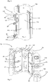
- Fig. 6 shows a representation of the blow mold carrier shells 70a, 70b. It can be seen that they have a polygonal outer circumference here, ie both carrier shell parts 70a and 70b each have four edges on their outer surfaces.
- Reference numerals 114 and 115 refer to surfaces of the blow mold carrier shells which in use are loaded by the pressure pad (not shown). The corresponding forces applied by the pressure pads here act essentially perpendicular to the two surfaces 114 and 115 Pressure pads are therefore also limited by the surfaces 114, 115 or sections of these surfaces. The surfaces are even or two-dimensional. The sealing means 82 and 84 abut against these surfaces.
- the reference numeral 116 refers to a holding member with which the blow moldings (not shown) are held on the blow mold carrier cups 70a, 70b.
- the reference numeral 118 denotes an engagement means, such as a claw, which holds the blow moldings in a closed state.
- this engagement means is pivotable, so that the blow molding can be decoupled from the carrier shells on this pivoting process.
- Fig. 7 shows a further illustration of a Blasformsammlungteils 6a.
- the sealing devices 82, 84 which in each case form or limit the two pressure pad devices 62, 64.
- the reference numeral 102 again indicates the area disposed between these two pressure pads and serves to fix the mold carrier shell portion to the blow molding support portion 6a.
- the sealing means 82, 84 are here, as mentioned above, arranged in a planar region and thus formed two-dimensionally, which is easier to accomplish than a three-dimensional course, which extends for example on a curved wall.
- the reference numerals 72, 74 respectively denote feed means by means of which the area surrounded by the seal means 82 and thus forming the pressure pads 62, 64 is pressurized with compressed air so as to push apart the blow mold tray portion and the blow mold support portion 6a.
- Reference numerals 104 and 106 refer to passage openings through which the fastening means 88 can be guided.
- the reference numeral 113 again indicates a suspension on which the Blasformangoteil 6a is articulated so as to be pivotable in this way.
- the attachment means may include spring means 89 which provide a clamping force which contract the mold carrier tray 70a and the blow mold carrier member 6a
- Fig. 8 shows a plan view of the in Fig. 7 shown device.
- the reference numeral 82 again indicates the sealing device and the reference numeral 75 a holding device, by which the sealing device is held on the Blasformangoteil.
- This holding device 75 may be, for example, a plate which is screwed by one or more screws on the Blasformitatiteil 6 a and which clamps a portion of the circumferential sealing means 82.
- a (also circumferential) portion 82a of the sealing device 82 bears against the blow mold carrier shell (not shown).
- the sealing devices are advantageously made of an elastomer and preferably run in a plane.
- the reference numeral a / 2 denotes the angle formed between the right-hand pressure pad and a mid-perpendicular. The total angle between these two pressure angles accordingly corresponds to that of the angle a.
- the pressure pads were divided into two equal parts and placed in a V-shaped arrangement at an optimum angle.
- the above-mentioned form-fitting holder or the fastening means 88 also provide for a fixed position of the now simplified two-dimensional seal 82. More specifically, this fixed position can be generated by the holding device 75, which may be a plate, for example.
- Fig. 9 shows a further embodiment of the device according to the invention. It can be seen that here the area surrounded by the sealing device 82 is reduced and thus also the pressure pad 62 is reduced in size. Thus, here the pressure pad surface was changed by the change of the sealing device 82 and in this way it is possible to control the position of the force on the Blasformitatischalen and also the size of the force targeted. If desired, webs could also pass through the respective pressure pad means 62 in order to further split the forces.
- Fig. 10 shows a representation of a Blasformitatischalenteils 70a.
- This Blasformitatischalenteil 70a serves to receive a blow molding.
- the blow mold carrier shell part 70a has an inner wall 142, in which a (only partially) visible opening 144 is arranged.
- the said opening 144 is formed within a recess 148.
- Reference numeral 145 denotes an inclined surface, which is an insertion of a blow molding, as in Fig. 12 shown, relieved.
- Reference numerals 162 and 164 denote terminals for supplying a tempering agent to the blow mold carrier shell portion.
- the actuating body 140 can via the in Fig. 6 shown pneumatic connection 150 with a pneumatic means, for example with compressed air, to be moved.
- Fig. 11 shows an enlarged view of the coupling region in the recess 148.
- the holding member 152 has a semi-circular or V-shaped cross section 152a, with which it behind the projection 154a of in Fig. 13 shown second retaining element 154 can engage.
- a nose or a projection 168 is provided, which engages in a corresponding recess 172 which is arranged on the blow molding part 4a, to center the Blasformmbateil.
- the stopper 146 further serves for correct positioning of the blow molding part 4a in the blow mold carrier shell 70a. In this way, a displacement of the blow molding 4a with respect to the Blasformitatischalenteil 70a in the longitudinal direction LR is prevented.
- Fig. 12 shows a representation of a blow molding 4a.
- This blow molded part has here the second holding element 154, which cooperates with the first holding element 152.
- the reference numeral 157 refers to a peripheral wall of the blow molding 4a, which abuts in a mounted state on the wall 142 of the Blasformitatischalenteils. Due to this surface contact between the walls 142 and 157, a heat transfer is also possible, so that with the aid of the tempering connections 162 and 164, the blow-molded part 4 a can also be tempered indirectly.
- the holding element 154 has a projection 154 a, which serves in a mounted state blow molding a Blasformitatischalenteil that the solid support member 152 can not be moved relative to the second support member 154. Furthermore, it can be seen that the second holding element 154 protrudes with respect to the wall 157th is trained. The first holding element 152 can thus engage in the second holding element 154.
- the reference numerals 153 relate to fastening means, such as screws, which are recessed here with respect to the wall 157 and with which the retaining element 154 is arranged on the blow molding 4a.
- the reference numeral 163 denotes a further recess in the wall 157, which facilitates insertion of the first retaining element 152 into the second retaining element 154.
- the recess 163 extends at least also in the direction E in which, during assembly, the blow-molded part is moved or rotated relative to the blow-mold carrier shell part 70a, i. in particular in a circumferential direction of the blow molding 4a.
- Fig. 14 shows a sectional view of an attached to the Blasformitatischalenteil 70a blow mold part 4a, wherein also the total marked 138 holding device is recognizable.
- the movable relative to the Blasformitatischalenteil 70a actuator body 140 which serves to clamp the blow molding 4a to the Blasformitatischalenteil 70a.
- the actuating body (140) extends through the wall 142 of the Blasformterägerschalenteils 70 a.
- the first holding element 152 can be seen, which engages behind the arranged on the blow molding second holding element.
- the reference numeral 6a refers to the blow mold carrier part on which the blow mold carrier shell part 70a is arranged.
- Components of the holding device 138 also extend through a wall of the Blasformitatiteils 6a, more precisely through in Fig. 7 shown opening 104.
- Fig. 15 shows a sectional view of a holding device 138.
- the actuator body 140 is movable in the direction R, wherein this direction also represents a radial direction of the blow molds or of the container to be expanded.
- the actuating body 140 is thereby guided by the wall 142, through which it extends.
- Reference numeral 188 refers to a sealing device.
- a piston member 204 is arranged and also fixed.
- the piston member 204 is movably disposed opposite to a piston space 206 in the direction R. It can be seen that the first retaining element 152, which is formed here in one piece with the actuating body 140, engages behind the second retaining element 154. The second holding element 154 protrudes into the recess 148, which is formed in the wall 142 is, inside.
- the reference numeral 202 refers to a formed on the actuating element 146 stage, against which the piston member 204 is supported.
- Fig. 16 shows a perspective view of the holding device 138.
- a pneumatic medium eg compressed air are supplied.
- the reference numeral 212 refers to a circumferential sealing device which seals the piston chamber 206.
- An end portion of the actuating body 140 extends into a sleeve body 124. In this case, this sleeve body 124 is arranged in the direction R fixed to the actuating body 140.
- the reference numeral 122 denotes a cover device which is screwed to the blow mold carrier shell part 70a and covers the holding device 138. The sleeve body extends through this covering device 122.
- the reference numeral 214 refers to a piston plate.
- Fig. 17 shows a further illustration of a blow molding, on which for the purpose of illustration the actuating body 140 is arranged, wherein its (not visible) retaining element engages behind the second retaining element 154.
Description
- Die vorliegende Erfindung bezieht sich auf eine Vorrichtung und ein Verfahren zum Umformen von Kunststoffvorformlingen zu Kunststoffbehältnissen. Derartige Vorrichtungen und Verfahren sind aus dem Stand der Technik seit langem bekannt. So ist es beispielsweise bekannt, dass Blasformen bzw. Blasformteile an Trägern angeordnet werden und diese Träger auseinander und zusammengeklappt werden können, wobei in einem geschlossenen Zustand der Blasform Kunststoffvorformlinge im Inneren dieser Blasform, insbesondere durch Beaufschlagung mit Druckluft zu Kunststoffbehältnissen expandiert werden.
- In der Regel sind dabei zwei Formträgerschalen vorgesehen, an denen jeweils fest die Blasformteile angeordnet sind. Diese Formträgerschalen sind wiederum an einem Blasformträger bzw. einem Blasformträgerteil angeordnet.
- Im Stand der Technik ist es bekannt, die Blasformteile mit Hilfe von Laschen zu befestigen. Diese Laschen können dabei in der Art von Spannpratzen ausgeführt sein, zu deren Betätigung im Allgemeinen ein Werkzeug zum Spannen notwendig ist. Mit einem fest definierten Drehmoment werden die Schrauben dieser Spannpratze beaufschlagt, um ein richtiges Spannen der Formschale in der Formträgerschale zu erreichen. Üblicherweise sind dabei bis zu drei derartiger Laschen zum Spannen für das linke und rechte Blasformteil nötig. Der dafür benötige Zeitaufwand zum Wechseln der Blasformteile bzw. der Formschalen beeinflusst die Stillstandszeit direkt.
- Das Dokument
US-A-2004202745 offenbart eine Vorrichtung und ein Verfahren gemäß den Oberbegriffen der Ansprüche 1 und 7. Steigende Produktionszahlen sind wichtige Kennwerte insbesondere für die Kunden der hier gegenständlichen Anlagen. Der vorliegenden Erfindung liegt daher die Aufgabe zu Grunde, Stillstandszeiten insbesondere Stillstandszeiten aufgrund von Garniturenwechseln zu verringern. Eine weitere Aufgabe der vorliegenden Erfindung liegt darin, ein Schnellwechselsystem zur Verfügung zu stellen, welches sich ohne Zusatzwerkzeug bedienen lässt. Eine weitere Aufgabe besteht darin, eine einfache und schnelle Handhabung zu erreichen, ohne dass hierfür ein manuelles Bedienen von Verriegelungen erforderlich ist. - Diese Aufgaben werden erfindungsgemäß durch die Gegenstände der unabhängigen Ansprüche erreicht.
- Vorteilhafte Ausführungsformen und Weiterbildungen sind Gegenstand der Unteransprüche. Eine erfindungsgemäße Vorrichtung zum Umformen von Kunststoffvorformlingen zu Kunststoffbehältnissen wird durch den Anspruch 1 offenbart. Die Halteeinrichtung weist einen Betätigungskörper auf, der sich durch eine in einer Wandung des Blasformträgerschalenteils und/oder eine in einer Wandung eines Blasformträgerteils ausgebildete Öffnung erstreckt, wobei dieser Betätigungskörper gegenüber der Wandung bewegbar ist und wobei an dem Betätigungskörper ein erstes Halteelement zum Halten des Blasformteils angeordnet ist.
- Vorteilhaft erstreckt sich daher der Betätigungskörper bzw. wenigstens ein Abschnitt dieses Betätigungskörpers durch die Wandung des Blasformträgerschalenteils und/oder die Wandung des Blasformträgerteils hindurch. Vorzugsweise umgibt daher das Blasformträgerschalenteil und/oder das Blasformträgerteil in dem Bereich, in dem der Betätigungskörper durch dieses Teil hindurchtritt, den Betätigungskörper in dessen Umfangsrichtung vollständig.
- Im Gegensatz zum Stand der Technik, bei dem üblicherweise die Blasformteile durch die erwähnten seitlich bewegbaren Haltepratzen eingespannt werden, wird nunmehr vorgeschlagen, die Montage bzw. die Halterung durch einen Betätigungskörper zu erreichen, der sich durch die besagte Wandung der Blasformträgerschale bzw. des Blasformträgerschalenteils erstreckt. Es wäre dabei auch möglich, dass eine Vollform verwendet wird. In diesem Fall würde sich der Betätigungskörper durch eine Öffnung in dem Blasformträgerteil erstrecken. Erfindungsgemäß ist dabei die Bewegung des Betätigungskörpers gegenüber der Wandung durch ein fließfähiges Medium und insbesondere pneumatisch erzeugbar. Es wäre jedoch auch möglich, dass die Bewegung des Betätigungskörpers hydraulisch initiiert wird oder auch durch magnetische Elemente, beispielsweise einen Elektromagneten. Ein entsprechendes (beispielsweise pneumatisch) angesteuertes Betätigungssystem ist daher in diesem System vorteilhaft im Wesentlichen vollständig in der Blasformträgerschale integriert. Ein Anschluss, beispielsweise ein pneumatischer Anschluss, kann direkt über das Blasformträgerschalenteil bei einem vorteilhaften Blasformträgerschalenteil in den Formträgerhälften verbaut sein. Bei dem Betätigungskörper kann es sich beispielsweise um ein Kolbenelement handeln, welches, wie oben erwähnt, pneumatisch bewegbar ist. Damit nimmt dieser Kolben bzw. der Betätigungskörper die Funktion eines Spannhakens wahr. Der Spannhaken stellt eine bevorzugte Ausführungsform des oben erwähnten Halteelements dar und nimmt vorteilhaft sowohl die Aufgabe einer Rasterstellung während des Einlegens des Blasformteils als auch andererseits die Aufgabe des Spannens des Blasformteils wahr.
- Bei einer vorteilhaften Ausführungsform ist an wenigstens einem Blasformträgerschalenteil ein Anschluss für ein fließfähiges Medium und insbesondere für ein gasförmiges Medium angeordnet.
- Bei einer weiteren vorteilhaften Ausführungsform weist der Betätigungskörper einen druckmittelbeaufschlagbaren Kolben auf. Dieser Kolben kann dabei in einem Zylindersystem angeordnet sein. An dem besagten Kolben ist wiederum vorteilhaft das Halteelement - bevorzugt fest - angeordnet.
- Bei einer weiteren vorteilhaften Ausführungsform ist die Öffnung in der Wandung in einer in der Wandung ausgebildeten Ausnehmung der Wandung angeordnet. Diese Wandung kann sich dabei in einer radialen Richtung der geschlossenen Blasform nach außen erstrecken. Durch diese Ausnehmung wird das Einlegen des jeweiligen Blasformteils erleichtert. Erfindungsgemäß ist an dem Blasformteil ein zweites Halteelement befestigt, welches zum Befestigen des Blasformteils an dem Blasformträgerschalenteil mit dem ersten Halteelement zusammen wirkt. So kann beispielsweise an dem Blasformteil ein Griffelement angeordnet sein, beispielsweise angeschraubt sein, in welches das besagte erste Halteelement eingreift. Durch das Zusammenwirken dieser beiden Halteelemente wird das Blasformteil an dem Blasformträgerschalenteil befestigt. Vorteilhaft ist dabei das zweite Halteelement starr mit dem Blasformteil verbunden. Erfindungsgemäß hintergreift in einem befestigen Zustand des Blasformteils an dem Blasformträgerschalenteil ein Halteelement, das zweite Halteelement. Vorteilhaft hintergreift das an dem Blasformträgerschalenteil angeordnete Halteelement das an dem Blasformteil angeordnete Halteelement.
- Bei einer weiteren vorteilhaften Ausführungsform steht das zweite Halteelement gegenüber einer Wandung des Blasformteils hervor. So kann das zweite Halteelement beispielsweise an einem Träger angeordnet sein und ein Abschnitt des Trägers kann gegenüber der besagten Wandung des Blasformteils hervorstehen. Dieser hervorstehende Abschnitt kann dabei in die oben erwähnte Ausnehmung in der Wandung des Blasformträgerschalenteils eingreifen.
- Dabei ist es möglich, dass das oben erwähnte Halteelement oder ein anderer Vorsprung in die Ausnehmung ragt, wobei jedoch auch umgekehrte Ausführungsformen denkbar sind. Vorteilhaft ist eine Relativbewegung des Blasformteils gegenüber den Blasformträgerschalenteilen nur in einem gelockerten Zustand der Halteeinrichtung möglich, nicht aber in einem fest montierten bzw. befestigten Zustand. Vorteilhaft handelt es sich bei dieser Relativbewegung um eine Drehbewegung des Blasformteils bezüglich einer vorgegebenen Drehachse gegenüber dem Blasformträgerschalenteil. Bei einer weiteren vorteilhaften Ausführungsform ist an dem Blasformträgerschalenteil auch eine Halterung für einen Blasformträger angeordnet.
- Bei einer weiteren vorteilhaften Ausführungsform ist in wenigstens einem Zustand trotz des Eingriffs der Halteelemente ineinander eine Relativbewegung eines Blasformteils gegenüber dem dieses Blasformteil haltenden Blasformträgerschalenteil ermöglicht. So ist es möglich, dass zum Einsetzen des Blasformteils dieses Blasformteil zunächst an das Blasformträgerteil angedrückt und anschließend in diesem angedrückten Zustand bewegt wird, um eine vorgegebene Endstellung zu erreichen. Erfindungsgemäß ist wenigstens ein Blasformträgerschalenteil an einem Blasformträgerteil angeordnet und zwischen dem Blasformträgerteil und dem Blasformträgerschalenteil ist eine Druckkissenanordnung ausgebildet. Durch diese Druckkissenanordnung können während des Expansionsvorgangs die beiden Blasformteile aufeinander zugedrückt werden und auf diese Weise kann eine Kontur der Behältnisse verbessert werden.
- Die vorliegende Erfindung ist weiterhin auf ein Verfahren zum Befestigen von Blasformteilen an Blasformträgerschalenteilen gemäß Anspruch 7 gerichtet. Das Blasformteil wird nach dem Anlegen an das Blasformträgerschalenteil gegenüber dem Blasformträgerschalenteil derart bewegt, dass an dem Blasformträgerschalenteil angeordnetes erstes Halteelement und ein an dem Blasformteil angeordnetes zweites Halteelement in Eingriff miteinander gelangen. Anschließend wird das an dem Blasformträgerschalenteil angeordnete erste Halteelement in einer weiteren Richtung bewegt, um das Blasformteil an dem Blasformträgerschalen zu arretieren, wobei die Bewegung des ersten Halteelements durch einen Betätigungskörper erzeugt wird, der sich wenigstens teilweise durch eine Wandung des Blasformträgerschalenteils erstreckt.
- Im Gegensatz zum Stand der Technik wird daher auch eine veränderte Vorgehensweise zum Befestigen des Blasformteils an dem Blasformträgerschalenteil vorgeschlagen. So ist es möglich, dass zunächst das Blasformteil an das Blasformschalenträgerteil angelegt und anschließend gegenüber diesem verdreht wird. Erst in diesem verdrehten Zustand wird das Blasformteil durch den besagten Betätigungskörper fest arretiert. Erfindungsgemäß erfolgt die Betätigung des Betätigungskörpers durch ein fließfähiges, insbesondere gasförmiges Medium und besonders bevorzugt pneumatisch. Bei der Verwendung einer pneumatischen Ansteuerung kann vorteilhaft die Versorgung mit Druckluft zum Druckaufbau zur Bewegung des Betätigungskörpers über eine Betriebsfunktion der gesamten Vorrichtung, wie beispielsweise einer Blasmaschine bzw. Streckblasmaschine, gesteuert werden. Erfindungsgemäß ist zwischen wenigstens einem Blasformträgerteil und dem an diesem Blasformträgerteil angeordneten Blasformteil eine Druckkissenanordnung angeordnet, wobei eine Druckkammer bzw. eine Druckkisseneinrichtung dieser Druckkissenanordnung mit einem fließfähigen Druckmittel beaufschlagbar ist, um durch eine zwischen dem Blasformträgerteil und dem Blasformteil wirkende Kraft das wenigstens eine Blasformträgerteil und das an diesem angeordnete Blasformteil auseinander zu drängen.
- Vorteilhaft ist die Druckkissenanordnung derart ausgebildet, dass die zwischen dem Blasformträgerteil und dem Blasformteil wirkende Kraft eine erste Teilkraft aufweist, die in einem ersten vorgegebenen - und bevorzugt räumlich definierbaren bzw. abgrenzbaren - und bevorzugt räumlich definierbaren bzw. abgrenzbaren - Bereich in der Umfangsrichtung des Blasformteils wirkt, so wie eine zweite Teilkraft, die in einem zweiten vorgegebenen Bereich in der Umfangsrichtung des Blasformteils wirkt, wobei der ersten Bereich und der zweite Bereich voneinander beabstandet sind und die Richtungen der ersten Teilkraft und der zweiten Teilkraft in einem vom 0 Grad unterschiedlichen Winkel zueinander verlaufen.. Die vorgegebenen Bereiche, in denen die Teilkräfte wirken, ergeben sich daher bevorzugt aus einer insbesondere geometrischen Gestalt der Druckkissenanordnung.
- Unter der Anordnung es Blasformteils an dem Blasformträgerteil wird verstanden, dass dieses Blasformteil zumindest mittelbar, d. h. ggfs. für weitere Elemente an dem Blasformträgerteil angeordnet ist. Üblicherweise ist das Blasformteil wiederum an einer Blasformträgerschale, im Folgenden auch kurz als Trägerschale angeordnet und diese Trägerschale ist bevorzugt an dem Blasformträgerteil angeordnet, wobei die erwähnte Druckkissenanordnung zwischen dem Blasformträgerteil und der besagten Trägerschale ausgebildet ist. Im Stand der Technik ist üblicherweise zwischen dem Blasformträgerteil und dem Blasformteil lediglich ein einheitliches Druckkissen angeordnet, welches mit Druckluft beaufschlagt werden kann. Entsprechend wirkt eine resultierende Kraft bei Beaufschlagung des Druckkissens nur in eine Richtung, sodass in dieser resultierenden Richtung die Blasform und der Blasformträger auseinandergedrückt werden. Durch diese lediglich eine Kraftwirkung kann es dabei während des Blasvorgangs zu Verspannungen kommen, die sich letztendlich auf die Gestalt des so entstehenden Kunststoffbehältnisses auswirken. Beim dem fließfähigen Medium, mit dem das Druckkissen beaufschlagt wird, handelt es sich insbesondere um ein gasförmiges Medium, bevorzugt um Luft und ggfs. um Sterilluft.
- Durch die bevorzugt vorgeschlagene Vorgehensweise wird die Lage und Ausführung des Druckkissens so gestaltet, dass die Verformung im Formträger und in der (Form)trägerschale reduziert wird. Genauer werden die durch das Druckkissen aufgebrachten Kräfte in wenigstens zwei Komponenten aufgeteilt, die unter unterschiedlichen Winkeln auf die Trägerschale bzw. die Blasform wirken, um damit das Risiko von Verspannungen während des Expansionsvorgangs reduzieren. Bei einer vorteilhaften Ausführungsform sind die beiden Teilkräfte unabhängig voneinander und besonders bevorzugt auch - insbesondere hinsichtlich ihrer Größen - unabhängig voneinander einstellbar.
- Vorzugsweise wirkt in der Umfangsrichtung zwischen den beiden Bereichen wenigstens abschnittsweise keine Kraft (abgesehen von einer sich aus den Teilkräften vekotriell zusammensetzenden Kraft) oder nur eine gegenüber den Teilkräften erheblich geringere Kraft, welche das Blasformteil und das Blasformträgerteil auseinanderdrängt.
- Bei einer vorteilhaften Ausführungsform weist die Vorrichtung zum Umformen von Kunststoffvorformlingen auch eine Beaufschlagungseinrichtung auf, welche die Kunststoffvorformlinge während des Expansionsvorgangs mit einem gasförmigen Medium und insbesondere mit Druckluft beaufschlagt, um diese zu expandieren.
- Weiterhin weist die Vorrichtung bevorzugt auch eine Reckstange auf, welche die Kunststoffvorformlinge während des Expansionsvorgangs in deren Längsrichtung dehnt.
- Bei einer weiteren vorteilhaften Ausführungsform ist auch eine Verriegelungseinrichtung vorgesehen, welche die Formträgerteile insbesondere während des Expansionsvorgangs miteinander verriegelt. Diese Verriegelung kann dabei kurvengesteuert eingreifen und derart ausgestaltet sein, dass zu Beginn des Expansionsvorgangs und auch im Verlauf des Expansionsvorgangs die beiden Formträgerteile miteinander verriegelt sind. Wie erwähnt, erlaubt die Ausgestaltung mit den zwei Teilkräften ein gleichmäßigeres Andrücken der beiden Blasformteile aneinander.
- Bei einer weiteren vorteilhaften Ausführungsform weist die Vorrichtung lediglich eine derartige Druckkissenanordnung an einem der beiden Formträger auf.
- Bei einer weiteren vorteilhaften Ausführungsform ist der Winkel zwischen der Richtung der ersten Teilkraft und der Richtung der zweiten Teilkraft zwischen 10° und 170°, bevorzugt zwischen 20° und 160°, bevorzugt zwischen 30° und 150°, bevorzugt zwischen 45° und 135°, bevorzugt zwischen 60° und 120° und besonders bevorzugt zwischen 75° und 105°. Diese Ausgestaltungen der Kraftrichtungen erlauben in besonders vorteilhafter Weise ein günstiges Andrücken der beiden Blasformteile aneinander. Damit ist insbesondere das Druckkissen in einer V-Anordnung angeordnet, sodass die beiden Kräfte in dem besagten Winkel zueinander stehen. Bei einer vorteilhaften Ausführungsform ist die Trägerschale über eine formschlüssige Halterung an dem Blasformträgerteil gehalten, sodass auch eine feste Lage des genannten Druckkissens erreicht wird.
- Bei einer weiteren vorteilhaften Ausführungsform weist die Druckkissenanordnung eine erste Druckkisseneinrichtung und eine zweite Druckkisseneinrichtung auf, welche wenigstens teilweise bzw. abschnittsweise voneinander getrennt sind und bevorzugt vollständig voneinander getrennt sind. Durch diese besagten Druckkisseneinrichtungen können die oben erwähnten beiden Kräfte ggfs. auch unabhängig voneinander auf die Blasform bzw. die Trägerschale aufgebracht werden. Es wäre jedoch auch möglich, dass lediglich eine Druckkisseneinrichtung vorgesehen ist, diese aber derart gestaltet wird, dass die beiden oben erwähnten Kräfte entstehen. Dies kann beispielsweise durch einen Steg innerhalb einer einzelnen Druckkisseneinrichtung erreicht werden, der dafür sorgt, dass in Umfangsrichtung der Blasform in einem zentralen Bereich zwischen den beiden erwähnten Teilkräften keine oder nur geringe Kräfte ausgeübt werden.
- Unter einer wenigstens teilweisen Trennung der Druckkisseneinrichtungen wird insbesondere verstanden, dass diese Druckkisseneinrichtungen zwar über einen Verbindungsabschnitt miteinander verbunden sein können, sich jedoch dieser Verbindungsabschnitt nicht entlang eines gesamten Seitenrandes wenigstens einer Druckkisseneinrichtung erstreckt sondern lediglich entlang eines Abschnitts eines derartigen Seitenrandes, der bevorzugt kleiner ist als 50% des Seitenrandes, bevorzugt kleiner als 30% des Seitenrandes, bevorzugt kleiner als 20% des Seitenrandes.
- Mit anderen Worten sind bei einer abschnittsweisen Trennung die Druckkisseneinrichtungen vorteilhaft lediglich über einen Verbindungsabschnitt miteinander verbunden, der sich auf weniger als 20% des Umfangs wenigstens einer der beiden Druckkisseneinrichtungen erstreckt, bevorzugt auf weniger als 10% des Umfangs, bevorzugt auf weniger als 5% des Umfangs.
Bei einer weiteren vorteilhaften Ausführungsform weist die Vorrichtung eine erste Zuführungseinrichtung auf, um der ersten Druckkisseneinrichtung das fließfähige Medium zuzuführen, so wie eine hiervon getrennte zweite Zuführungseinrichtung, um der zweiten Druckkisseneinrichtung das fließfähige Medium zuzuführen. Auf diese Weise ist eine unterschiedliche Steuerung der beiden Druckkisseneinrichtungen möglich. Auch können die Zuführungskanäle für die beiden Druckkisseneinrichtungen vollständig voneinander getrennt sein, es wäre jedoch auch möglich, dass den beiden Druckkisseneinrichtungen über einen gemeinsamen Anschluss das fließfähige Medium, d. h. die Druckluft zugeführt wird. - Bei einer weiteren vorteilhaften Ausführungsform weist die Druckkissenanordnung eine umlaufende Dichtungseinrichtung auf, welche den mit dem fließfähigen Druckmittel beaufschlagten Raum, d. h. die Druckkammer, abgrenzt, und diese Dichtungseinrichtung liegt an einem ebenen Wandbereich an. Im Stand der Technik werden üblicherweise dreidimensional anliegende Dichtungseinrichtungen verwendet, d. h. insbesondere Dichtungseinrichtungen, welche sich auch entlang eines gekrümmten Abschnitts der Trägerschale bzw. der Blasform oder Blasformträgers erstrecken. In dieser Ausführungsform wird vorgeschlagen, dass sich die Dichtungseinrichtung lediglich entlang einer Ebene d. h. einer geraden Ebene und damit nur im zweidimensionalen Bereich erstreckt. Auf diese Weise ist eine verbesserte Dichtwirkung möglich.
- Bei einer weiteren vorteilhaften Ausführungsform ist die Druckkissenanordnung zwischen dem Blasformträgerteil und einer das Blasformteil haltenden Trägerschale angeordnet. Diese Trägerschale kann dabei derart ausgestaltet sein, dass das Blasformteil lösbar von dieser Trägerschale ausgestaltet ist.
- Bei einer weiteren vorteilhaften Ausführungsform weist die Vorrichtung eine Halteeinrichtung zum Halten des Blasformteils an dem Blasformträgerteil auf, und diese Halteeinrichtung ist in einer Umfangsrichtung der Blasform zwischen Bereichen der Druckkissenanordnung angeordnet. Bei dieser Ausführungsform wird vorgeschlagen, dass eine bezüglich der Druckkissenanordnung bevorzugt zentrale Anordnung der Halteeinrichtung vorgesehen ist, welche beispielsweise, falls nur eine Druckkisseneinrichtung vorgesehen ist, an einem entsprechenden begrenzenden Steg vorgesehen sein kann.
- Bevorzugt ist jedoch die Halteeinrichtung zwischen der ersten Druckkisseneinrichtung und der zweiten Druckkisseneinrichtung angeordnet. Bevorzugt wird in einem Bereich dieser Halteeinrichtung durch das Druckkissen selbst keine Kraft in Richtung der Blasform ausgeübt.
- Es wird auch ein vorteilhaftes Verfahren zum Umformen von Kunststoffvorformlingen zu Kunststoffbehältnissen beschrieben, wobei eine Blasform vorgesehen ist, welche zwei bezüglich einander beweglich angeordnete Blasformteile aufweist, welche in einem geschlossenen Zustand der Blasform einen Hohlraum ausbilden, in dessen Inneren die Kunststoffvorformlinge durch Beaufschlagung mit einem fließfähigen Medium und insbesondere mit Druckluft zu den Kunststoffbehältnissen expandiert werden.
- Dabei ist das erste Blasformteil an einem ersten Blasformträgerteil angeordnet und das zweite Blasformteil an einem zweiten Blasformträgerteil. Das erste Blasformträgerteil wird gegenüber dem zweiten Blasformträgerteil zum Öffnen und Schließen der Blasform bewegt. Weiterhin ist zwischen wenigstens einem Blasformträgerteil an dem an diesem Blasformträgerteil (zumindest mittelbar) angeordneten Blasformteil eine Druckkissenanordnung angeordnet, wobei eine Druckkammer bzw. eine Druckeinrichtung dieser Druckkissenanordnung mit einem fließfähigen Druckmittel beaufschlagt wird, um durch eine zwischen dem Blasformträgerteil und dem Blasformteil wirkende Kraft das wenigstens eine Blasformträgerteil und das an diesem angeordnete Blasformteil auseinander zu drängen.
- Vorteilhaft ist die Druckkissenanordnung derart ausgebildet, dass die zwischen dem Blasformträgerteil und dem Blasformteil wirkende Kraft eine erste Teilkraft aufweist, die in einem ersten vorgegebenen Bereich in der Umfangsrichtung des Blasformteils wirkt, so wie eine zweite Teilkraft, die in einem zweiten vorgegebenen Bereich in der Umfangsrichtung des Blasformteils wirkt, wobei der erste Bereich und der zweite Bereich voneinander beabstandet sind und die Richtungen der ersten Teilkraft und der zweiten Teilkraft in einem von 0 Grad unterschiedlichem Winkel zueinander verlaufen.
- Es wird daher auch verfahrensmäßig vorgeschlagen, dass die Druckkissenanordnung so ausgeführt wird, dass wenigstens zwei Teilkräfte vorgesehen sind, welche auf das Blasformteil bzw. eine das Blasformteil haltende Trägerschale wirken.
- Bei einem bevorzugten Verfahren wirkt eine zwischen dem Blasformteil und dem Blasformträgerteil wirkende Haltekraft in der Umfangsrichtung der Blasform zwischen der ersten Teilkraft und der zweiten Teilkraft.
- Weitere Vorteile und Ausführungsformen ergeben sich aus den beigefügten Zeichnungen. Darin zeigen:
- Fig. 1
- eine Behandlungsanlage für Behältnisse nach dem Stand der Technik;
- Fig. 2
- eine Darstellung einer Blasstation nach dem Stand der Technik;
- Fig. 3a, b
- zwei schematische Darstellungen zur Veranschaulichung der Erfindung;
- Fig. 4
- eine erfindungsgemäße Blasstation zum Umformen von Kunststoffvorformlingen zu Kunststoffbehältnissen;
- Fig. 5
- eine teilweise Ansicht einer Blasstation zum Umformen von Kunststoffvorformlingen zu Kunststoffbehältnissen;
- Fig. 6
- eine Darstellung einer Trägerschale zum Tragen von Blasformen;
- Fig. 7
- eine Darstellung eines erfindungsgemäßen Blasformträgerteils;
- Fig. 8
- eine Draufsicht auf das in
Fig. 7 gezeigte Blasformträgerteil; - Fig. 9
- eine weitere Ansicht eines erfindungsgemäßen Blasformträgerteils;
- Fig. 10
- eine erste Darstellung eines Blasformträgerschalenteils;
- Fig. 11
- eine vergrößerte Darstellung eines Bereichs des in
Fig. 10 gezeigten Blasformträgerschalenteils; - Fig. 12
- eine Darstellung eines Blasformteils;
- Fig. 13
- eine vergrößerte Darstellung eines Teils des in
Fig. 12 gezeigten Blasformteils; - Fig. 14.
- eine Schnittdarstellung zur Veranschaulichung der Halteeinrichtung;
- Fig. 15
- eine Schnittdarstellung der Halteeinrichtung;
- Fig. 16
- eine perspektivische Darstellung der Halteeinrichtung; und
- Fig. 17
- eine weitere Darstellung eines Blasformteils mit daran angeordnetem Betätigungskörper.
-
Figur 1 zeigt eine schematische Darstellung einer Anlage zum Herstellen von Kunststoffbehältnissen nach dem Stand der Technik. Diese Anlage 50 weist eine Heizeinrichtung 30 auf, in der Kunststoffvorformlinge 10 erwärmt werden. Dabei werden diese Kunststoffvorformlinge 10 mittels einer Transporteinrichtung 34, wie hier einer umlaufenden Kette, durch diese Heizeinrichtung 30 geführt und dabei mit einer Vielzahl von Heizelementen 31 erwärmt. An diese Heizeinrichtung 30 schließt sich eine Übergabeeinheit 36 an, welche die Vorformlinge 10 an eine Sterilisationseinrichtung 32 übergibt. Diese Sterilisationseinrichtung 32 weist dabei hier ebenfalls ein Transportrad 37 auf und an diesem Transportrad 37 oder auch stationär können Sterilisationselemente angeordnet sein. In diesem Bereich ist beispielsweise eine Sterilisation durch Wasserstoffperoxidgas oder auch durch elektromagnetische Strahlung möglich. Insbesondere wird in diesem Bereich eine Innensterilisation der Vorformlinge durchgeführt. - Das Bezugszeichen 20 bezeichnet in seiner Gesamtheit einen Reinraum, dessen Außenbegrenzungen hier durch die punktierte Linie L angedeutet sind. In einer weiteren bevorzugten Ausführungsform ist der Reinraum 20 nicht nur im Bereich des Transportrads 2 und Befüllungseinrichtung 40 angeordnet, sondern beginnt möglicherweise schon im Bereich der Heizeinrichtung 30, der Sterilisationseinrichtung 32, der Kunststoffvorformlingzuführung und/oder der Kunststoffvorformlingherstellung. Man erkennt, dass dieser Reinraum 20 in dem Bereich der Sterilisationseinheit 32 beginnt. In diesem Bereich können Schleuseneinrichtungen vorgesehen sein, um die Kunststoffvorformlinge in den Reinraum 20 einzuführen, ohne dass dabei zu viel Gas innerhalb des Reinraums strömt und so verloren geht.
- Der Reinraum ist, wie durch die gestrichelte Linie L angedeutet, an die Außengestalt der einzelnen Anlagenkomponenten angepasst. Auf diese Weise kann das Volumen des Reinraums reduziert werden.
- Das Bezugszeichen 1 bezeichnet in ihrer Gesamtheit eine Umformungsvorrichtung, bei der an einem Transportrad 2 eine Vielzahl von Blasstationen bzw. Umformungsstationen 8 angeordnet ist, wobei hier lediglich einer dieser Blasstationen 8 dargestellt ist. Mit diesen Blasstationen 8 werden die Kunststoffvorformlinge 10 zu Behältnissen 10a expandiert. Obwohl hier nicht detailliert gezeigt, befindet sich nicht der gesamte Bereich des Transporteinrichtung 2 innerhalb des Reinraums 20, sondern der Reinraum 20 bzw. Isolator ist gewissermaßen als Mini-Isolator innerhalb der gesamten Vorrichtung realisiert. So wäre es möglich, dass der Reinraum zumindest im Bereich der Umformungsvorrichtung 1 kanalartig ausgeführt ist.
- Das Bezugszeichen 22 bezieht sich auf eine Zuführeinrichtung, welche die Vorformlinge an die Umformungseinrichtung 1 übergibt und das Bezugszeichen 24 auf eine Abführeinrichtung, welche die hergestellten Kunststoffbehältnisse 20 von der Umformungsvorrichtung 1 abführt. Man erkennt, dass der Reinraum 20 in dem Bereich der Zuführeinrichtung 22 und der Abführeinrichtung 24 jeweils Ausnehmungen aufweist, welche diese Einrichtungen 22, 24 aufnehmen. Auf diese Weise kann in besonders vorteilhafter Weise eine Übergabe der Kunststoffvorformlinge 10 an die Umformungsvorrichtung 1 bzw. eine Übernahme der Kunststoffbehältnisse 10a von der Umformungsvorrichtung 1 erreicht werden.
- Mit einer Übergabeeinheit 42 werden die expandierten Kunststoffbehältnisse an eine Befüllungseinrichtung 40 übergeben und von dieser Befüllungseinrichtung 40 anschließend über eine weitere Transporteinheit 44 abgeführt. Dabei befindet sich auch die Befüllungseinrichtung 40 innerhalb des besagten Reinraums 20. Auch im Falle der Befüllungseinrichtung wäre es möglich, dass nicht die gesamte Befüllungseinrichtung 40 mit beispielsweise einem Reservoir für ein Getränk vollständig innerhalb des Reinraums 6 angeordnet sind, sondern auch hier lediglich diejenigen Bereiche, in denen tatsächlich die Behältnisse geführt werden. Insoweit könnte auch die Befüllungseinrichtung in ähnlicher Weise aufgebaut sein wie die Vorrichtung 1 zum Umformen von Kunststoffvorformlingen 10.
- Wie erwähnt, ist der Reinraum 20 im Bereich der Vorrichtung 1 auf einen geringst möglichen Bereich reduziert, nämlich im Wesentlichen auf die Blasstationen 8 selbst. Durch diese kleinbauende Gestaltung des Reinraums 20 ist es leichter und schneller möglich, einen Reinraum überhaupt herzustellen und auch die Sterilhaltung in der Betriebsphase ist weniger aufwändig. Auch wird weniger Sterilluft benötigt, was zu kleineren Filteranlagen führt und auch die Gefahr von unkontrollierter Wirbelbildung wird reduziert.
-
Figur 2 zeigt eine Detaildarstellung der Vorrichtung 1 im Bereich einer Blasstation 8. Eine Vielzahl derartiger Blasstationen 8 wird mit einer Transporteinrichtung 2 bzw. einem Träger drehend um eine Achse X bewegt. Die Blasstation 8 ist, wie inFigur 2 ersichtlich, innerhalb des Reinraums 20, der hier kanalartig ausgebildet ist, geführt. Dieser Reinraum 20 wird abgeschlossen durch eine bewegliche Seitenwand 19 und einen einteilig mit dieser Seitenwand 19 ausgebildeten Deckel 17. Diese Seitenwand 19 und der Deckel 17 drehen dabei mit der Blasstation 8 mit. - Das Bezugszeichen 18 bezieht sich auf eine weitere Wandung, welche den Reinraum 16 begrenzt. Diese Wandung 18 ist hier eine außen liegende Wandung, welche stationär angeordnet ist. Zwischen dem Deckel 17 und der Wandung 18 ist eine Dichtungseinrichtung 25 vorgesehen, welche die gegeneinander beweglichen Elemente 17 und 18 gegeneinander abdichtet, beispielsweise, wie oben erwähnt, unter Verwendung eines Wasserschlosses. Der untere Bereich der Wandung 18 ist fest und abdichtend an einem Boden 13 angeordnet. Innerhalb des Reinraums 20 und hier unmittelbar an der Wandung 19 anliegend ist ein Träger 26 vorgesehen, der sich ebenfalls drehend bewegt und an dem wiederum eine Halteeinrichtung 23 vorgesehen ist, welche die Blasstation 8 hält.
- Das Bezugszeichen 11 bezieht sich auf eine Folgeeinrichtung, welche von einer Führungskurve 9 betätigt werden kann, um die Blasstation auf ihrem Weg durch den Reinraum 6 zu öffnen und zu schließen, um insbesondere den Kunststoffvorformling in die Blasstation einzulegen und um ihn auch wieder zu entnehmen. Dabei ist eine Führungskurve 9 auch innerhalb des Reinraums 20 angeordnet. Es wäre jedoch beispielsweise auch möglich, etwa bereits einen Abschnitt 11 unterhalb der einzelnen Blasstationen 8 aus dem Reinraum 20 herauszuführen.
- Die Transporteinrichtung 2 kann noch weitere Elemente aufweisen, welche oberhalb des Reinraums 20 angeordnet sind.
- Der Träger 26 ist dabei fest auf einem Haltekörper 29 angeordnet und dieser Haltekörper ist wiederum beweglich gegenüber dem Boden 13. Dabei bezieht sich das Bezugszeichen 27 auf eine weitere Dichtungseinrichtung, welche auch in diesem Bereich eine Abdichtung der gegeneinander beweglichen Bereiche 13 und 29 bewirkt.
- Das Bezugszeichen 5 bezieht sich auf eine Reckstange, welche gegenüber der Blasstation beweglich ist, um die Kunststoffvorformlinge 10 in ihrer Längsrichtung zu recken. Dabei ist auf dem Deckel 17 hier ein Schlitten 12 angeordnet, demgegenüber die Reckstange in der Richtung Y beweglich ist. Das Bezugszeichen 21 bezieht sich auf eine weitere Halterung für diesen Schlitten 12 der Reckstange 5.
- Man erkennt, dass bestimmte Bereiche der Reckstange während des Blasvorgangs sowohl außerhalb des Reinraums 20 als auch innerhalb des Reinraums 20 sind. Zu diesem Zweck ist es möglich, außerhalb des Reinraums 20 bzw. oberhalb des Schlittens 12 eine Schutzeinrichtung wie einen Faltenbalg vorzusehen, der die Reckstange 5 umgibt, so dass kein Bereich der Reckstange 5 unmittelbar mit der Außenumgebung in Berührung kommt. Das Bezugszeichen U kennzeichnet die (unsterile) Umgebung des Reinraums 20. Das Bezugszeichen 28 kennzeichnet einen Träger zum Tragen einer Bodenform, welche ebenfalls einen Bestandteil der Blasform 4 ausbildet. Dieser Träger ist dabei ebenfalls in der Richtung Y bewegbar.
- Das Bezugszeichen 55 bezieht sich auf eine Sterilisationseinrichtung, welche hier bevorzugt im Inneren des Reinraums 20 angeordnet ist und zum Sterilisieren der einzelnen Umformungsstationen bzw. Bestandteilen dieser Umformungsstationen 8 dient. Diese Sterilisationseinrichtung 55 kann dabei die Umformungsstationen 8 beispielsweise mit Wasserstoffperoxid oder einem anderen Sterilisationsmittel beaufschlagen. Dabei kann die Sterilisationseinrichtung 55 stationär angeordnet sein und die Umformungsstationen können sich gegenüber dieser Sterilisationseinrichtung 55 bewegen. Diese Sterilisationseinrichtung bzw. Beaufschlagungseinrichtung 55 kann sich am Transportrad 2 oder an der stehenden Wandung 18 befinden oder generell stationär angeordnet sein und aus Düsen o ähnlichem bestehen. Zudem ist es vorteilhaft, Sterilluft zum Sterilisieren des Reinraums 20 über das Lüftungssystem in den Reinraum 20 einzubringen.
- Die (nicht gezeigten) Blasformen sind innerhalb der Blasformträger 6 angeordnet. Genauer können dabei zwei Blasformträgerteile angeordnet sein, die gegenüber einander schwenkbar sind und jeweils ein Blasformteil halten. Durch diesen Schwenkvorgang können die Blasformen zum Einbringen von Kunststoffvorformlingen und zum Entnehmen fertig geblasener Behältnisse geöffnet werden. Diese Blasformträger und Blasformen sind dabei ebenfalls innerhalb des Reinraums angeordnet.
- Es wäre jedoch auch (anders als in
Fig. 2 gezeigt) möglich und bevorzugt, dass die Transporteinrichtung 2 bzw. der Träger einen C-förmigen Außenumfang aufweist, der auch teilweise die Außenwandungen des Reinraums ausbildet. Damit dreht sich hier diese C - förmige Reinraumwand mit der Transporteinrichtung 2 d.h. dem Blasrad. Bei dieser Ausführungsform ist die untere Begrenzung des Reinraums von dem Boden 13 beabstandet und bewegt sich relativ zu dem Boden. Auf diese Weise kann der Reinraum noch kleiner gestaltet werden als inFig.2 gezeigt. Eine Abdichtung dieses C- förmigen Profils der Transporteinrichtung, welches hier sowohl eine Innenwandung als auch eine untere und obere Abdeckung des Reinraums ausbildet, findet hier bevorzugt nur gegenüber der Außenwandung des Reinraums statt. Diese Außenwandung ist dabei vorteilhaft stationär angeordnet. - Die in den
Figuren 1 und 2 gezeigte Anordnung bezieht sich auf eine sterile Blasformanordnung. Die vorliegende Erfindung ist jedoch ebenso bei herkömmlichen bzw. unsterilen Blasformmaschinen anwendbar. Auch das inFigur 1 gezeigte Anlagenkonzept ist sowohl für sterile als auch für nicht sterile Maschinen anwendbar. - Die
Fig. 3a und 3b zeigen zwei schematische Darstellungen zur Veranschaulichung des der Erfindung zugrundeliegenden Problems und dessen Lösung.Fig. 3a zeigt die Verhältnisse nach dem Stand der Technik Dabei ist hier ein Blasformträgerteil 6a vorgesehen, an dem eine Blasform 4a (ggfs. über eine Trägerschale) angeordnet ist.. Es wäre jedoch auch denkbar, die Blasformen direkt an dem Träger zu befestigen. Zwischen dem Blasformträger 6a und der Blasform 4a ist ein in der Umfangsrichtung UR vorgesehenes Druckkissen angeordnet, welches zwischen den beiden Dichtungsabschnitten 182a und 182b ausgebildet ist. Dieses Druckkissen erzeugt damit eine resultierende Kraft Fres, die hier horizontal wirkt. Die kleinen Kraftpfeile im Inneren der Blasformen beziehen sich auf die Kräfte, welche durch den eigentlichen Blasvorgang entstehen. Dies bedeutet, dass es auf diese Weise zu Verspannungen und auch zu Verformungen der Blasform oder auch der Blasformträgerschale kommen kann. -
Fig. 3b zeigt eine erfindungsgemäße Ausgestaltung. Im Gegensatz zum Stand der Technik sind hier zwei durch die umlaufenden Dichtungen 82, 84 voneinander beabstandete Druckkissen vorgesehen, die hier Teilkräfte F1 und F2, die in dem vorgegebenen Winkel zueinander angeordnet sind, auf die Blasform 4a bzw. die Trägerschale für die Blasform ausüben. Die Bezugszeichen 82, 84 kennzeichnen damit Dichtungseinrichtungen, welche die beiden Druckkissen umgeben bzw. ausbilden. Durch die Wirkung mit zwei Teilkräften F1 und F2 kann eine insgesamt gleichmäßigere Kraftwirkung auf die Blasform 4a bzw. die Trägerschale ausgeübt werden. Diese beiden Bereiche B1 und B2 in denen die Teilkräfte wirken, sind hier in der Umfangsrichtung UR der Blasform voneinander beabstandet. Der Winkel a, unter dem die beiden Kräfte F1 und F2 zueinander verlaufen, liegt vorteilhaft in einem Bereich zwischen 70° und 110°. - Die Umfangsrichtung ist vorteilhaft auch eine Umfangsrichtung des zu expandierenden Kunststoffvorformlings bzw. Behältnisses. Der erwähnte Winkel α wird vorteilhaft in einer durch die Umfangsrichtung gebildeten Ebene gebildet. Diese Ebene steht dabei vorteilhaft zu einer Längsrichtung des Kunststoffvorformlings senkrecht und ist vorteilhaft parallel zu der Figurenebene von
Fig. 3b -
Fig. 4 zeigt eine perspektivische Darstellung einer erfindungsgemäßen Blasstation 8. Diese Blasstation 8 weist dabei zwei Blasformteile 4a, 4b auf, die hier in einem geschlossenen Zustand dargestellt sind. Zwischen diesen beiden Blasformteilen 4a, 4b wird der oben erwähnte Hohlraum ausgebildet, innerhalb dessen die Kunststoffvorformlinge zu den Kunststoffbehältnissen expandiert werden. - Das Blasformteil 4a und entsprechend auch das Blasformteil 4b sind hier an Blasformträgerschalenteilen 70a, 70b fest angeordnet, beispielsweise verklemmt oder verschraubt. Diese Blasformträgerschalen 70a, 70b sind wiederum sind wiederum an Blasformträgerteilen 6a und 6b angeordnet. Diese Blasformträgerteile sind bezüglich einer gemeinsamen Schwenkachse 112 schwenkbar, um die Blasform zu öffnen und zu schließen.
- Das Bezugszeichen 92 bezieht sich auf ein erstes Verriegelungselement, in welches ein zweites Verriegelungselement 94 zum Verriegeln der Blasform während des Expansionsvorgangs eingreift. Zu diesem Zweck ist dieses zweite Verriegelungselement 94 bezüglich einer Schwenkwelle 105 schwenkbar.
- Das Bezugszeichen 88 bezieht sich auf Befestigungsmittel bzw. Halteeinrichtungen, welche zum Befestigen der Blasformträgerschalen 70a und 70b an den jeweiligen Blasformträgerteilen 6a, 6b dienen.
- Über Zuführungen 108 wird die Druckluft zum Betreiben des Druckkissens zur Verfügung gestellt. Das Bezugszeichen 110 kennzeichnet ein Verriegelungselement, welches zum schnellen Ver- und Entriegeln der Blasformträgerschalen 55a und 55b gegenüber dem zugehörigen Blasformträgerteilen 6a und 6b dient.
-
Fig. 5 zeigt eine Teildarstellung der inFig. 4 gezeigten Vorrichtung, d. h. ein Blasformträgerteil 6a mit dem darin angeordneten Blasträgerschalenteil und dem Blasformteil 4a. Auch erkennt man hier einen Anschluss 120, über den dem Blasformteil 4a ein Temperiermedium, beispielsweise eine erwärmte Flüssigkeit, zugeführt werden kann. -
Fig. 6 zeigt eine Darstellung der Blasformträgerschalen 70a, 70b. Man erkennt, das diese hier einen polygonalen Außenumfang aufweisen, d. h. beide Trägerschalenteile 70a und 70b weisen an ihren Außenflächen jeweils vier Kanten auf. Die Bezugszeichen 114 und 115 beziehen sich auf Flächen der Blasformträgerschalen, die im Betrieb von dem (nicht gezeigten) Druckkissen belastet werden. Die entsprechenden durch die Druckkissen aufgebrachten Kräfte wirken hier im Wesentlichen senkrecht zu den beiden Flächen 114 und 115. Die Druckkissen werden daher auch durch die Flächen 114, 115 bzw. Abschnitte dieser Flächen begrenzt. Die Flächen sind hier eben bzw. zweidimensional. Die Dichtungseinrichtungen 82 und 84 liegen an diesen Flächen an. - Das Bezugszeichen 116 bezieht sich auf ein Halteelement, mit dem die Blasformteile (nicht gezeigt) an den Blasformträgerschalen 70a, 70b gehalten werden. Das Bezugszeichen 118 kennzeichnet ein Eingriffsmittel, wie eine Pratze, welche die Blasformteile in einem geschlossenen Zustand hält. Vorteilhaft ist dabei dieses Eingriffsmittel schwenkbar, sodass über diesen Schwenkvorgang die Blasformteile von den Trägerschalen entkoppelt werden können.
- Man erkennt hier ebenfalls wieder die Befestigungsmittel 88, mit denen die Blasformträgerschalen an den Blasformträgern angeordnet werden können. Diese Befestigungseinrichtungen sind hier zwischen den beiden Flächen 115 und 114 angeordnet und damit zwischen denjenigen Bereichen, in denen im Betrieb die jeweiligen Teilkräfte F1 und F2 anliegen. An dem zweiten Blasformschalenteil 70b liegt im Betrieb kein Druckkissen an, d. h. das Druckkissen liegt hier nur an einem der beiden Blasformschalenteilen an. Dies ist jedoch auch ausreichend, um die beiden Blasformteile aufeinander zuzudrängen.
-
Fig. 7 zeigt eine weitere Darstellung eines Blasformträgerteils 6a. Hier erkennt man die Dichtungseinrichtungen 82, 84, welche hier jeweils die beiden Druckkisseneinrichtungen 62, 64 ausbilden bzw. begrenzen. Das Bezugszeichen 102 kennzeichnet wiederum den Bereich der zwischen diesen beiden Druckkissen angeordnet ist und der zum Befestigen der Formträgerschalenteils an dem Blasformträgerteil 6a dient. Die Dichtungseinrichtungen 82, 84 sind hier, wie oben erwähnt, in einem ebenen Bereich angeordnet und damit zweidimensional ausgebildet, was leichter zu bewerkstelligen ist als ein dreidimensionaler Verlauf, der sich beispielsweise an einer gekrümmten Wandung erstreckt. - Die Bezugszeichen 72, 74 kennzeichnen jeweils Zuführeinrichtungen, mittels denen der Bereich, der von der Dichtungseinrichtung 82 umgeben ist, und der damit die Druckkissen 62, 64 ausbildet, mit Druckluft beaufschlagt wird, um so das Blasformträgerschalenteil und das Blasformträgerteil 6a auseinander zu drücken. Die Bezugszeichen 104 und 106 beziehen sich auf Durchgangsöffnungen, durch welche hindurch die Befestigungsmittel 88 führbar sind. Das Bezugszeichen 113 kennzeichnet wiederum eine Aufhängung, an der das Blasformträgerteil 6a angelenkt ist, um auf diese Weise schwenkbar zu sein. Die Befestigungsmittel können Federeinrichtungen 89 aufweisen, welche eine Spannkraft bewirken, welche die Formträgerschale 70a und das Blasformträgerteil 6a zusammenziehen
-
Fig. 8 zeigt eine Draufsicht auf die inFig. 7 gezeigte Vorrichtung. Das Bezugszeichen 82 kennzeichnet wiederum die Dichtungseinrichtung und das Bezugszeichen 75 eine Halteeinrichtung, durch welche die Dichtungseinrichtung an dem Blasformträgerteil gehalten wird. Bei dieser Halteeinrichtung 75 kann es sich beispielsweise um eine Platte handeln, die durch eine oder mehrere Schrauben an dem Blasformträgerteil 6a angeschraubt ist und welche einen Abschnitt der umlaufenden Dichtungseinrichtung 82 einklemmt. Ein (ebenfalls umlaufender) Abschnitt 82a der Dichtungseinrichtung 82 liegt an der (nicht gezeigten) Blasformträgerschale an. Die Dichtungseinrichtungen sind vorteilhaft aus einem Elastomer hergestellt und verlaufen bevorzugt in einer Ebene. - Das Bezugszeichen a/2 kennzeichnet den Winkel, der zwischen dem rechten Druckkissen und einer Mittelsenkrechten gebildet wird. Der Gesamtwinkel zwischen diesen beiden Druckwinkeln entspricht demnach dem des Winkels a.
- Damit wurden hier die Druckkissen in zwei gleiche Teile aufgeteilt und in eine V-förmige Anordnung unter einem optimalen Winkel gebracht. Die oben erwähnte formschlüssige Halterung bzw. die Befestigungsmittel 88 sorgen zudem für eine feste Lage der nun vereinfachten zweidimensionalen Dichtung 82. Genauer gesagt kann diese feste Lage durch die Halteeinrichtung 75, bei der es sich beispielsweise um eine Platte handeln kann, erzeugt werden.
-
Fig. 9 zeigt eine weitere Ausführungsform der erfindungsgemäßen Vorrichtung. Man erkennt, dass hier der von der Dichtungseinrichtung 82 umgebene Bereich verkleinert ist und damit auch das Druckkissen 62 verkleinert ist. Damit wurde hier die Druckkissenfläche durch den Wechsel der Dichtungseinrichtung 82 verändert und auf diese Weise ist es möglich, die Lage der Krafteinwirkung auf die Blasformträgerschalen und auch die Größe der Kraft gezielt zu steuern. Falls gewünscht, könnten durch die jeweiligen Druckkisseneinrichtungen 62 auch Stege verlaufen, um die Kräfte noch weiter aufzuspalten. -
Fig. 10 zeigt eine Darstellung eines Blasformträgerschalenteils 70a. Dieses Blasformträgerschalenteil 70a dient zur Aufnahme eines Blasformteils. Dazu weist das Blasformträgerschalenteil 70a eine Innenwandung 142 auf, in der eine (nur teilweise) sichtbare Öffnung 144 angeordnet ist. Durch diese Öffnung 144 erstreckt sich ein ebenfalls nur teilweise sichtbarer Betätigungskörper 140, an dem ein erstes Halteelement 152 angeordnet ist. Dabei ist die besagte Öffnung 144 innerhalb einer Ausnehmung 148 ausgebildet. Das Bezugszeichen 145 kennzeichnet eine Schrägfläche, die ein Einführen eines Blasformteils, wie inFig. 12 gezeigt, erleichtert. Die Bezugszeichen 162 und 164 kennzeichnen Anschlüsse, um dem Blasformträgerschalenteil ein Temperiermittel zuzuführen. Der Betätigungskörper 140 kann über den inFig. 6 gezeigten Pneumatikanschluss 150 mit einem Pneumatikmittel, beispielsweise mit Druckluft, bewegt werden. -
Fig. 11 zeigt eine vergrößerte Darstellung des Kopplungsbereiches in der Ausnehmung 148. Man erkennt, dass das Halteelement 152 einen halbkreisförmigen bzw. V-förmigen Querschnitt 152a aufweist, mit dem es hinter den Vorsprung 154a des inFig. 13 gezeigten zweiten Halteelements 154 eingreifen kann. Weiterhin ist eine Nase bzw. ein Vorsprung 168 vorgesehen, der in eine entsprechende Ausnehmung 172, die an dem Blasformteil 4a angeordnet ist, eingreift, um das Blasformträgerteil zu Zentrieren. Der Anschlag 146 dient weiterhin zum korrekten Positionieren des Blasformteils 4a in der Blasformträgerschale 70a. Auf diese Weise wird ein Verschieben des Blasformteils 4a gegenüber dem Blasformträgerschalenteil 70a in der Längsrichtung LR verhindert. -
Fig. 12 zeigt eine Darstellung eines Blasformteils 4a. Dieses Blasformteil weist hier das zweite Halteelement 154 auf, welches mit dem ersten Halteelement 152 zusammenwirkt. Das Bezugszeichen 157 bezieht sich auf eine Umfangswandung des Blasformteils 4a, welche in einem montierten Zustand an der Wandung 142 des Blasformträgerschalenteils anliegt. Durch diesen flächigen Kontakt zwischen den Wandungen 142 und 157 wird auch ein Wärmeübertrag ermöglicht, sodass mit Hilfe der Temperieranschlüsse 162 und 164 indirekt auch das Blasformteil 4a selbst temperiert werden kann. - Das Halteelement 154 weist einen Vorsprung 154a auf, der in einem montierten Zustand Blasformteils einem Blasformträgerschalenteil dazu dient, dass das feste Halteelement 152 nicht mehr gegenüber dem zweiten Halteelement 154 verschoben werden kann. Weiterhin erkennt man, dass das zweite Halteelement 154 vorstehend bezüglich der Wandung 157 ausgebildet ist. Das erste Halteelement 152 kann damit in das zweite Halteelement 154 einrasten. Die Bezugszeichen 153 beziehen sich auf Befestigungsmittel, wie beispielsweise Schrauben, welche hier bezüglich der Wandung 157 versenkt sind und mit welchen das Halteelement 154 an dem Blasformteil 4a angeordnet ist. Das Bezugszeichen 163 kennzeichnet eine weitere Ausnehmung in der Wandung 157, welche ein Einführen des ersten Halteelements 152 in das zweite Halteelement 154 erleichtert.
- Die Ausnehmung 163 erstreckt sich zumindest auch in der Richtung E, in der während der Montage das Blasformteil gegenüber dem Blasformträgerschalenteil 70a bewegt bzw. gedreht wird, d.h. insbesondere in einer Umfangsrichtung des Blasformteils 4a.
-
Fig. 14 zeigt eine Schnittdarstellung eines an dem Blasformträgerschalenteil 70a montierten Blasformteils 4a, wobei auch die insgesamt mit 138 gekennzeichnete Halteeinrichtung erkennbar ist. Im einzelnen erkennt man den gegenüber dem Blasformträgerschalenteil 70a bewegbaren Betätigungskörper 140, der zum Spannen des Blasformteils 4a an dem Blasformträgerschalenteil 70a dient. Man erkennt, dass sich der Betätigungskörper (140) durch die Wandung 142 des Blasformterägerschalenteils 70a erstreckt. Daneben ist auch das erste Halteelement 152 erkennbar, welches das an dem Blasformteil angeordnete zweite Halteelement hintergreift. Das Bezugszeichen 6a bezieht sich auf das Blasformträgerteil, an dem das Blasformträgerschalenteil 70a angeordnet ist. Bestandteile der Halteeinrichtung 138 erstrecken sich dabei auch durch eine Wandung des Blasformträgerteils 6a, genauer durch die inFig. 7 gezeigte Öffnung 104. -
Fig. 15 zeigt eine Schnittdarstellung einer Halteeinrichtung 138. Der Betätigungskörper 140 ist dabei in der Richtung R beweglich, wobei diese Richtung auch einer radiale Richtung der Blasformen bzw. auch des zu expandierenden Behältnisses darstellt. Der Betätigungskörper 140 wird dabei von der Wandung 142, durch die er sich hindurch erstreckt, geführt. Das Bezugszeichen 188 bezieht sich auf eine Dichtungseinrichtung. An dem Betätigungskörper 140 ist ein Kolbenelement 204 angeordnet und auch fixiert. - Das Kolbenelement 204 ist gegenüber einem Kolbenraum 206 in der Richtung R beweglich angeordnet. Man erkennt, dass das erste Halteelement 152, welches hier einteilig mit dem Betätigungskörper 140 ausgebildet ist, das zweite Halteelement 154 hintergreift. Das zweite Halteelement 154 ragt dabei in die Ausnehmung 148, welche in der Wandung 142 ausgebildet ist, hinein. Das Bezugszeichen 202 bezieht sich auf eine an dem Betätigungselement 146 ausgebildete Stufe, gegenüber der sich das Kolbenelement 204 abstützt.
-
Fig. 16 zeigt eine perspektivische Darstellung der Halteinrichtung 138. Über Öffnungen 208 kann dem Kolbenraum 206 ein Pneumatikmedium, z.B. Druckluft zugeführt werden. Hierdurch wird das Kolbenelement 204 und mit diesem der Betätigungskörper 140 nach links gedrängt und damit das Blasformteil 4a an das Blasformträgerschalenteil 70a herangezogen. Das Bezugszeichen 212 bezieht sich auf eine umlaufende Dichtungseinrichtung, welche den Kolbenraum 206 abdichtet. Ein Endabschnitt des Betätigungskörpers 140 erstreckt sich in einen Hülsenkörper 124. Dabei ist dieser Hülsenkörper 124 in der Richtung R fest an dem Betätigungskörper 140 angeordnet. Das Bezugszeichen 122 kennzeichnet eine Abdeckeinrichtung, die an dem Blasformträgerschalenteil 70a angeschraubt ist und die Halteeinrichtung 138 abdeckt. Der Hülsenkörper erstreckt sich durch diese Abdeckeinrichtung 122 hindurch. - Es wäre weiterhin denkbar, ein Federungselement vorzusehen, welches den Betätigungskörper 140 in der Richtung R oder einer hierzu entgegengesetzten Richtung vorspannt. Das Bezugszeichen 214 bezieht sich auf einen Kolbenteller.
-
Fig. 17 zeigt eine weitere Darstellung eines Blasformteils, an dem zur Veranschaulichung der Betätigungskörper 140 angeordnet ist, wobei dessen (nicht sichtbares) Halteelement das zweite Halteelement 154 hintergreift. -
- 1
- Umformungsvorrichtung
- 2
- Transportrad, Transporteinrichtung
- 4
- Blasform
- 4a, b
- Blasformteile
- 5
- Reckstange
- 6
- Blasformträger
- 6a, b
- Blasformträgerteile
- 8
- Umformungsstationen, Blasstationen
- 9
- Führungskurve
- 10
- Kunststoffvorformlinge
- 10a
- Behältnisse
- 11
- Folgeeinrichtung, Abschnitt
- 12
- Schlitten
- 13
- Boden
- 17
- Deckel
- 18
- Wandung
- 19
- bewegliche Seitenwand
- 20
- Reinraum
- 21
- Halterung
- 22
- Zuführeinrichtung
- 23
- Halteeinrichtung
- 24
- Abführeinrichtung
- 25
- Dichtungseinrichtung
- 26
- Träger
- 27
- Dichtungseinrichtung
- 28
- Träger
- 29
- Haltekörper
- 30
- Heizeinrichtung
- 31
- Heizelemente
- 32
- Sterilisationseinrichtung
- 34
- Transporteinrichtung
- 36
- Übergabeeinheit
- 37
- Transportrad
- 40
- Befüllungseinrichtung
- 42
- Übergabeeinheit
- 44
- Transporteinheit
- 50
- Anlage
- 55
- Sterilisationseinrichtung
- 62, 64
- Druckkisseneinrichtungen
- 70a, b
- Blasformträgerschalenteile
- 74
- Zuführeinrichtungen
- 75
- Halteeinrichtung
- 82, 84
- Dichtungseinrichtungen
- 82a
- Dichtungsabschnitt
- 88
- Halteeinrichtung, Befestigungsmittel
- 92
- Verriegelungselement
- 94
- Verriegelungselement
- 102
- Bereich zwischen den Druckkissen
- 104
- Öffnung
- 105
- Schwenkwelle
- 106
- Durchgangsöffnungen
- 108
- Zuführungen
- 110
- Verriegelungselement
- 112
- Schwenkachse
- 113
- Aufhängung
- 114, 115
- Flächen der Blasformträgerschalen
- 116
- Halteelement
- 118
- Eingriffsmittel
- 122
- Abdeckeinrichtung
- 124
- Hülsenkörper
- 138
- Halteeinrichtung
- 140
- Betätigungskörper
- 142
- (Innen)wandung
- 144
- Öffnung
- 146
- Anschlag
- 145
- Schrägfläche
- 148
- Ausnehmung
- 150
- Pneumatikanschluß
- 152
- erstes Halteelement, Betätigungskörper
- 152a
- Querschnitt
- 153
- Befestigungsmittel
- 154
- zweites Halteelement
- 154a
- Vorsprung
- 157
- Umfangswandung des Blasformteils
- 162, 164
- Temperieranschlüsse
- 163
- Ausnehmung
- 182a, b
- Dichtungseinrichtung (StdT)
- 188
- Dichtungseinrichtung
- 194
- O-Ring
- 202
- Stufe
- 204
- Kolbenelement
- 206
- Kolbenraum
- 208
- Öffnungen
- 212
- umlaufende Dichtungseinrichtung
- 214
- Kolbenteller
- B1, B2
- Bereiche
- F1, F2
- Teilkräfte
- E
- Richtung
- R
- Bewegungsrichtung des Betätigungskörpers 146
- Fres
- Kraft
- L
- Linie
- LR
- Längsrichtung
- UR
- Umfangsrichtung
- Y
- Richtung
- α
- Winkel
Claims (7)
- Vorrichtung (1) zum Umformen von Kunststoffvorformlingen (10) zu Kunststoffbehältnissen mit einer Blasform (4), welche wenigstens zwei bezüglich einander beweglich angeordnete Blasformteile (4a, 4b) aufweist, welche in einem geschlossenen Zustand der Blasform (4) einen Hohlraum ausbilden, in dessen Innerem die Kunststoffvorformlinge (10) durch Beaufschlagung mit einem fließfähigen Medium zu den Kunststoffbehaltnissen (10a) expandierbar sind, wobei das erste Blasformteil (4a) demontierbar an einem ersten Blasformträgerschalenteil (70a) angeordnet ist und das zweite Blasformteil (4b) demontierbar an einem zweiten Blasformträgerschalenteil (70b) angeordnet ist und das erste Blasformträgerschalenteil (70a) gegenüber dem zweiten Blasformträgerschalenteil (70b) zum Öffnen und Schließen der Blasform (4) bewegbar ist, und wobei zum Halten wenigstens eines Blasformteils (4a, 4b) an dem ihm zugeordneten Blasformträgerschalenteil (70a, 70b) eine Halteeinrichtung (138) vorgesehen ist, welche einen Betätigungskörper (140) aufweist, der sich durch eine in einer Wandung (142) des Blasformträgerschalenteils (70a, 70b) und/oder eines Blasformträgerteils (6a, 6b) ausgebildete Öffnung (144) erstreckt, wobei dieser Betätigungskörper (140) gegenüber der Wandung (142) bewegbar ist und wobei an dem Betatigungskörper (140) ein erstes Halteelement (152) zum Halten des Blasformteils (4a, 4b) angeordnet ist
dadurch gekennzeichnet, dass
die Bewegung des Betätigungskörpers (140) gegenüber der Wandung (142) durch ein fließfähiges Medium und insbesondere pneumatisch erzeugbar ist und wenigstens ein Blasformträgerschalenteil (70a) an einem Blasformträgerteil (6a) angeordnet ist und zwischen dem Blasformtragerteil (6) und dem Blasformträgerschalenteil (70a) eine Druckkissenanordnung ausgebildet ist, wobei an dem Blasformteil (4a, 4b) ein zweites Halteelement (154) befestigt ist, welches zum Befestigen des Blasformteils (4a, 4b) an dem Blasformträgerschalenteil (70a, 70b) mit dem ersten Halteelement zusammenwirkt und in einem befestigten Zustand des Blasformteils (4a, 4b) an dem Blasformträgerschalenteil (70a, 70b) ein Halteelement (152, 154) das zweite Halteelement (154, 152) hintergreift. - Vorrichtung nach Anspruch 1
dadurch gekennzeichnet, dass
an wenigstens einem Blasformträgerschalenteil (70a, 70b) ein Anschluss für ein fließfähiges Medium angeordnet ist. - Vorrichtung nach wenigstens einem der vorangegangenen Ansprüche,
dadurch gekennzeichnet, dass
der Betätigungskörper (140) einen druckmittelbeaufschlagbaren Kolben (152) aufweist. - Vorrichtung nach wenigstens einem der vorangegangenen Ansprüche,
dadurch gekennzeichnet, dass
die Öffnung (144) in einer in der Wandung (142) ausgebildeten Ausnehmung (148) der Wandung angeordnet ist. - Vorrichtung nach Anspruch 1,
dadurch gekennzeichnet, dass
das zweite Halteelement (154) gegenüber einer Wandung (162) des Blasformteils (4a, 4b) hervorsteht. - Vorrichtung nach Anspruch 1,
dass in wenigstens einem Zustand trotz eines Eingriffs der Halteelemente ineinander eine Relativbewegung eines Blasformteils (4a, 4b) gegenüber dem dieses Blasformteil (4a, 4b) haltendenden Blasformträgerschalenteil (70a, 70b) ermöglicht ist. - Verfahren zum Befestigen von Blasformteilen (4a, 4b) an Blasformträgerschalenteilen (70a, 70b), wobei das Blasformteil (4a, 4b) in einer vorgegebenen Positionierung an dem Blasformträgerschalenteil (70a, 70b) angelegt wird und das Blasformteil (4a, 4b) nach dem Anlegen an das Blasformträgerschalenteil (70a, 70b) gegenüber dem Blasformträgerschalenteil (70a, 70b) bewegt wird, derart, dass ein an dem Blasformträgerschalenteil angeordnetes erstes Halteelement (152) und ein an dem Blasformteil (4a, 4b) befestigtes zweites Halteelement (154), welches zum Befestigen des Blasformteils (4a, 4b) an dem Blasformträgerschalenteil (70a, 70b) mit dem ersten Halteelement zusammenwirkt, in Eingriff miteinander gelangen, und anschließend das an dem Blasformträgerschalenteil angeordnete erste Halteelement (152) in einer weiteren Richtung bewegt wird, um das Blasformteil (4a, 4b) an dem Blasformträgerschalenteil zu arretieren und wobei die Bewegung des ersten Halteelements (152) durch einen Betätigungskörper (140) erzeugt wird, der sich wenigstens teilweise durch eine Wandung 142) des Blasformträgerschalenteils (70a, 70b) erstreckt
dadurch gekennzeichnet, dass
der Betätigungskörper (140) gegenüber der Wandung (142) durch ein fließfähiges Medium und insbesondere pneumatisch bewegt wird, wobei wenigstens ein Blasformträgerschalenteil (70a) an einem Blasformträgerteil (6a) angeordnet ist und zwischen dem Blasformträgerteil (6) und dem Blasformträgerschalenteil (70a) eine Druckkissenanordnung ausgebildet ist und in einem befestigten Zustand des Blasformteils (4a, 4b) an dem Blasformträgerschalenteil (70a, 70b) ein Halteelement (152, 154) das zweite Halteelement (154, 152) hintergreift.
Applications Claiming Priority (1)
| Application Number | Priority Date | Filing Date | Title |
|---|---|---|---|
| DE102011052863.6A DE102011052863B4 (de) | 2011-08-19 | 2011-08-19 | Vorrichtung zum Umformen von Kunststoffvorformlingen zu Kunststoffbehältnissen und Verfahren zum Befestigen von Blasformteilen an Blasformträgerschalenteilen |
Publications (3)
| Publication Number | Publication Date |
|---|---|
| EP2559544A2 EP2559544A2 (de) | 2013-02-20 |
| EP2559544A3 EP2559544A3 (de) | 2014-01-29 |
| EP2559544B1 true EP2559544B1 (de) | 2018-06-13 |
Family
ID=46934388
Family Applications (1)
| Application Number | Title | Priority Date | Filing Date |
|---|---|---|---|
| EP12179848.2A Active EP2559544B1 (de) | 2011-08-19 | 2012-08-09 | Vorrichtung und Verfahren zum Umformen von Kunststoffvorformlingen zu Kunststoffbehältnissen mit Druckkissen |
Country Status (4)
| Country | Link |
|---|---|
| US (1) | US9457524B2 (de) |
| EP (1) | EP2559544B1 (de) |
| CN (1) | CN102950758B (de) |
| DE (1) | DE102011052863B4 (de) |
Families Citing this family (4)
| Publication number | Priority date | Publication date | Assignee | Title |
|---|---|---|---|---|
| DE102014107512B4 (de) * | 2014-05-28 | 2016-02-25 | Krones Ag | Blasformeinrichtung mit vorspannbarer Befestigung für Blasformen |
| FR3038541B1 (fr) | 2015-07-08 | 2017-07-21 | Sidel Participations | Dispositif de moulage pour une machine de fabrication de recipients en matiere thermoplastique |
| ITUB20160870A1 (it) * | 2016-02-19 | 2017-08-19 | Sipa Progettazione Automaz | Stampo di soffiaggio |
| FR3053906B1 (fr) | 2016-12-12 | 2018-08-17 | Sidel Participations | Dispositif de moulage pour la mise en œuvre de procedes de moulage a chaud et de moulage a froid |
Citations (4)
| Publication number | Priority date | Publication date | Assignee | Title |
|---|---|---|---|---|
| US6099286A (en) * | 1998-05-29 | 2000-08-08 | Wentworth Mould And Die Company | Universal mold carrier with improved air flow compensation |
| DE60001269T2 (de) * | 1999-03-08 | 2004-01-22 | Sidel | Formeinheit die eine verbesserte formschliessklemmeinrichung aufweist und extrusionsblasformmaschine wo diese fromschliessklemmeinrichtung verwendet wird |
| DE202004011785U1 (de) * | 2004-07-27 | 2004-10-14 | Krones Ag | Blasformbehälter und Formblasmaschine |
| US20050142243A1 (en) * | 2003-12-30 | 2005-06-30 | Wentworth Mold Inc. | Air flow compensation for mold carrier |
Family Cites Families (8)
| Publication number | Priority date | Publication date | Assignee | Title |
|---|---|---|---|---|
| FR2659265B1 (fr) * | 1990-03-06 | 1992-06-26 | Sidel Sa | Procede de dispositif pour fabriquer des recipients en matieres thermoplastiques par soufflage ou etirage-soufflage. |
| DE20007429U1 (de) * | 2000-04-22 | 2001-05-23 | Krones Ag | Blasform und Blasmaschine |
| FR2813231B1 (fr) | 2000-08-31 | 2003-05-09 | Sidel Sa | Unite de moulage comportant une chambre de compensation delimitee par une membrane, membrane pour une telle unite et machine munie d'une telle unite |
| US6913455B2 (en) | 2003-04-11 | 2005-07-05 | Wentworth Mold Inc. | Hot fill mold shell assembly with reduced heat transfer |
| FR2903933B1 (fr) | 2006-07-21 | 2008-10-03 | Sidel Participations | Dispositif de moulage pour la fabrication de recipients thermoplastiques |
| EP2263854B1 (de) * | 2008-12-19 | 2013-05-01 | Krones AG | Elektrisch betriebene Blasformmaschine und das Verfahren |
| US8070470B2 (en) * | 2009-02-06 | 2011-12-06 | Wentworth Mold Ltd. | Mold assembly |
| DE102009050637B4 (de) | 2009-05-06 | 2019-06-19 | Krones Aktiengesellschaft | Blasformanordnung |
-
2011
- 2011-08-19 DE DE102011052863.6A patent/DE102011052863B4/de active Active
-
2012
- 2012-07-31 US US13/562,979 patent/US9457524B2/en active Active
- 2012-08-09 EP EP12179848.2A patent/EP2559544B1/de active Active
- 2012-08-17 CN CN201210294766.6A patent/CN102950758B/zh active Active
Patent Citations (4)
| Publication number | Priority date | Publication date | Assignee | Title |
|---|---|---|---|---|
| US6099286A (en) * | 1998-05-29 | 2000-08-08 | Wentworth Mould And Die Company | Universal mold carrier with improved air flow compensation |
| DE60001269T2 (de) * | 1999-03-08 | 2004-01-22 | Sidel | Formeinheit die eine verbesserte formschliessklemmeinrichung aufweist und extrusionsblasformmaschine wo diese fromschliessklemmeinrichtung verwendet wird |
| US20050142243A1 (en) * | 2003-12-30 | 2005-06-30 | Wentworth Mold Inc. | Air flow compensation for mold carrier |
| DE202004011785U1 (de) * | 2004-07-27 | 2004-10-14 | Krones Ag | Blasformbehälter und Formblasmaschine |
Also Published As
| Publication number | Publication date |
|---|---|
| CN102950758B (zh) | 2016-03-16 |
| EP2559544A2 (de) | 2013-02-20 |
| EP2559544A3 (de) | 2014-01-29 |
| DE102011052863B4 (de) | 2022-12-22 |
| US20130193624A1 (en) | 2013-08-01 |
| CN102950758A (zh) | 2013-03-06 |
| US9457524B2 (en) | 2016-10-04 |
| DE102011052863A1 (de) | 2013-02-21 |
Similar Documents
| Publication | Publication Date | Title |
|---|---|---|
| EP2559545B1 (de) | Vorrichtung sowie Verfahren zum Blasformen von Kunststoffvorformlingen zu Kunststoffbehältnissen mit Druckkissen | |
| EP2495086B1 (de) | Blasmaschine mit Blasformverriegelung im Reinraum | |
| EP2382076B1 (de) | Verfahren und vorrichtung zur blasformung von behältern | |
| EP2144742A1 (de) | Vorrichtung zur blasformung von behältern | |
| WO2007012308A1 (de) | Vorrichtung zur herstellung von blasformsegmenten | |
| EP2618986B1 (de) | Verfahren und vorrichtung zur blasformung von behältern | |
| EP2139665A1 (de) | Verfahren und vorrichtung zur blasformung von behältern | |
| DE102005017540A1 (de) | Verfahren und Vorrichtung zur Blasformung von Behältern | |
| EP3088161B1 (de) | Verfahren und aufheizvorrichtung zur temperaturkonditionierung von vorformlingen sowie blasformungsmaschine mit einer solchen vorrichtung | |
| EP3055120B1 (de) | Verfahren und vorrichtung zum herstellen eines mit füllgut gefüllten behälters | |
| DE102004045405A1 (de) | Vorrichtung zur Blasformung von Behältern | |
| EP2559544B1 (de) | Vorrichtung und Verfahren zum Umformen von Kunststoffvorformlingen zu Kunststoffbehältnissen mit Druckkissen | |
| DE10354506A1 (de) | Vorrichtung zur Blasformung von Behältern | |
| DE102014107512B4 (de) | Blasformeinrichtung mit vorspannbarer Befestigung für Blasformen | |
| EP3416803B1 (de) | Zangenanordnung für die handhabung von vorformlingen und transferrad und behälterbehandlungsmaschine mit einer solchen zangenanordnung | |
| DE102011053577A1 (de) | Blasmaschine mit demontierbaren Blasstationen | |
| EP3571035B1 (de) | Schnellwechseldorn mit aktiver preformklemmung | |
| EP2694270B1 (de) | Vorrichtung zur blasformung von behältern | |
| EP2913174B1 (de) | Blasformmaschine mit Zentrierung des Blasformbodens | |
| EP3064334B1 (de) | Verfahren und aufheizvorrichtung zur temperaturkonditionierung von vorformlingen sowie blasformungsmaschine mit einer solchen vorrichtung | |
| EP2237941B1 (de) | Verfahren und vorrichtung zur blasformung von behältern | |
| DE102014019722A1 (de) | Blasformeinrichtung mit vorspannbarer Befestigung für Blasformen | |
| EP1473139A1 (de) | Verfahren und Vorrichtung zur Blasformung von Behältern | |
| WO2023174805A1 (de) | Umformmaschine für die umformung von vorformlingen in behälter und betriebsverfahren einer solchen |
Legal Events
| Date | Code | Title | Description |
|---|---|---|---|
| PUAI | Public reference made under article 153(3) epc to a published international application that has entered the european phase |
Free format text: ORIGINAL CODE: 0009012 |
|
| AK | Designated contracting states |
Kind code of ref document: A2 Designated state(s): AL AT BE BG CH CY CZ DE DK EE ES FI FR GB GR HR HU IE IS IT LI LT LU LV MC MK MT NL NO PL PT RO RS SE SI SK SM TR |
|
| AX | Request for extension of the european patent |
Extension state: BA ME |
|
| PUAL | Search report despatched |
Free format text: ORIGINAL CODE: 0009013 |
|
| AK | Designated contracting states |
Kind code of ref document: A3 Designated state(s): AL AT BE BG CH CY CZ DE DK EE ES FI FR GB GR HR HU IE IS IT LI LT LU LV MC MK MT NL NO PL PT RO RS SE SI SK SM TR |
|
| AX | Request for extension of the european patent |
Extension state: BA ME |
|
| RIC1 | Information provided on ipc code assigned before grant |
Ipc: B29C 49/42 20060101AFI20131220BHEP Ipc: B29C 49/48 20060101ALN20131220BHEP |
|
| 17P | Request for examination filed |
Effective date: 20140729 |
|
| RBV | Designated contracting states (corrected) |
Designated state(s): AL AT BE BG CH CY CZ DE DK EE ES FI FR GB GR HR HU IE IS IT LI LT LU LV MC MK MT NL NO PL PT RO RS SE SI SK SM TR |
|
| 17Q | First examination report despatched |
Effective date: 20160909 |
|
| RIC1 | Information provided on ipc code assigned before grant |
Ipc: B29C 49/42 20060101AFI20170929BHEP Ipc: B29C 49/48 20060101ALN20170929BHEP |
|
| RIC1 | Information provided on ipc code assigned before grant |
Ipc: B29C 49/42 20060101AFI20171027BHEP Ipc: B29C 49/48 20060101ALN20171027BHEP |
|
| GRAP | Despatch of communication of intention to grant a patent |
Free format text: ORIGINAL CODE: EPIDOSNIGR1 |
|
| RIC1 | Information provided on ipc code assigned before grant |
Ipc: B29C 49/48 20060101ALN20171124BHEP Ipc: B29C 49/42 20060101AFI20171124BHEP Ipc: B29C 49/06 20060101ALN20171124BHEP Ipc: B29C 33/30 20060101ALN20171124BHEP Ipc: B29C 49/36 20060101ALN20171124BHEP |
|
| INTG | Intention to grant announced |
Effective date: 20180102 |
|
| GRAS | Grant fee paid |
Free format text: ORIGINAL CODE: EPIDOSNIGR3 |
|
| GRAA | (expected) grant |
Free format text: ORIGINAL CODE: 0009210 |
|
| AK | Designated contracting states |
Kind code of ref document: B1 Designated state(s): AL AT BE BG CH CY CZ DE DK EE ES FI FR GB GR HR HU IE IS IT LI LT LU LV MC MK MT NL NO PL PT RO RS SE SI SK SM TR |
|
| REG | Reference to a national code |
Ref country code: GB Ref legal event code: FG4D Free format text: NOT ENGLISH |
|
| REG | Reference to a national code |
Ref country code: CH Ref legal event code: EP Ref country code: AT Ref legal event code: REF Ref document number: 1008008 Country of ref document: AT Kind code of ref document: T Effective date: 20180615 |
|
| REG | Reference to a national code |
Ref country code: IE Ref legal event code: FG4D Free format text: LANGUAGE OF EP DOCUMENT: GERMAN |
|
| REG | Reference to a national code |
Ref country code: DE Ref legal event code: R096 Ref document number: 502012012864 Country of ref document: DE Ref country code: FR Ref legal event code: PLFP Year of fee payment: 7 |
|
| REG | Reference to a national code |
Ref country code: NL Ref legal event code: MP Effective date: 20180613 |
|
| REG | Reference to a national code |
Ref country code: LT Ref legal event code: MG4D |
|
| PG25 | Lapsed in a contracting state [announced via postgrant information from national office to epo] |
Ref country code: ES Free format text: LAPSE BECAUSE OF FAILURE TO SUBMIT A TRANSLATION OF THE DESCRIPTION OR TO PAY THE FEE WITHIN THE PRESCRIBED TIME-LIMIT Effective date: 20180613 Ref country code: SE Free format text: LAPSE BECAUSE OF FAILURE TO SUBMIT A TRANSLATION OF THE DESCRIPTION OR TO PAY THE FEE WITHIN THE PRESCRIBED TIME-LIMIT Effective date: 20180613 Ref country code: LT Free format text: LAPSE BECAUSE OF FAILURE TO SUBMIT A TRANSLATION OF THE DESCRIPTION OR TO PAY THE FEE WITHIN THE PRESCRIBED TIME-LIMIT Effective date: 20180613 Ref country code: NO Free format text: LAPSE BECAUSE OF FAILURE TO SUBMIT A TRANSLATION OF THE DESCRIPTION OR TO PAY THE FEE WITHIN THE PRESCRIBED TIME-LIMIT Effective date: 20180913 Ref country code: FI Free format text: LAPSE BECAUSE OF FAILURE TO SUBMIT A TRANSLATION OF THE DESCRIPTION OR TO PAY THE FEE WITHIN THE PRESCRIBED TIME-LIMIT Effective date: 20180613 Ref country code: CY Free format text: LAPSE BECAUSE OF FAILURE TO SUBMIT A TRANSLATION OF THE DESCRIPTION OR TO PAY THE FEE WITHIN THE PRESCRIBED TIME-LIMIT Effective date: 20180613 Ref country code: BG Free format text: LAPSE BECAUSE OF FAILURE TO SUBMIT A TRANSLATION OF THE DESCRIPTION OR TO PAY THE FEE WITHIN THE PRESCRIBED TIME-LIMIT Effective date: 20180913 |
|
| PG25 | Lapsed in a contracting state [announced via postgrant information from national office to epo] |
Ref country code: GR Free format text: LAPSE BECAUSE OF FAILURE TO SUBMIT A TRANSLATION OF THE DESCRIPTION OR TO PAY THE FEE WITHIN THE PRESCRIBED TIME-LIMIT Effective date: 20180914 Ref country code: RS Free format text: LAPSE BECAUSE OF FAILURE TO SUBMIT A TRANSLATION OF THE DESCRIPTION OR TO PAY THE FEE WITHIN THE PRESCRIBED TIME-LIMIT Effective date: 20180613 Ref country code: LV Free format text: LAPSE BECAUSE OF FAILURE TO SUBMIT A TRANSLATION OF THE DESCRIPTION OR TO PAY THE FEE WITHIN THE PRESCRIBED TIME-LIMIT Effective date: 20180613 Ref country code: HR Free format text: LAPSE BECAUSE OF FAILURE TO SUBMIT A TRANSLATION OF THE DESCRIPTION OR TO PAY THE FEE WITHIN THE PRESCRIBED TIME-LIMIT Effective date: 20180613 |
|
| PG25 | Lapsed in a contracting state [announced via postgrant information from national office to epo] |
Ref country code: NL Free format text: LAPSE BECAUSE OF FAILURE TO SUBMIT A TRANSLATION OF THE DESCRIPTION OR TO PAY THE FEE WITHIN THE PRESCRIBED TIME-LIMIT Effective date: 20180613 |
|
| PG25 | Lapsed in a contracting state [announced via postgrant information from national office to epo] |
Ref country code: CZ Free format text: LAPSE BECAUSE OF FAILURE TO SUBMIT A TRANSLATION OF THE DESCRIPTION OR TO PAY THE FEE WITHIN THE PRESCRIBED TIME-LIMIT Effective date: 20180613 Ref country code: SK Free format text: LAPSE BECAUSE OF FAILURE TO SUBMIT A TRANSLATION OF THE DESCRIPTION OR TO PAY THE FEE WITHIN THE PRESCRIBED TIME-LIMIT Effective date: 20180613 Ref country code: IS Free format text: LAPSE BECAUSE OF FAILURE TO SUBMIT A TRANSLATION OF THE DESCRIPTION OR TO PAY THE FEE WITHIN THE PRESCRIBED TIME-LIMIT Effective date: 20181013 Ref country code: PL Free format text: LAPSE BECAUSE OF FAILURE TO SUBMIT A TRANSLATION OF THE DESCRIPTION OR TO PAY THE FEE WITHIN THE PRESCRIBED TIME-LIMIT Effective date: 20180613 Ref country code: EE Free format text: LAPSE BECAUSE OF FAILURE TO SUBMIT A TRANSLATION OF THE DESCRIPTION OR TO PAY THE FEE WITHIN THE PRESCRIBED TIME-LIMIT Effective date: 20180613 Ref country code: RO Free format text: LAPSE BECAUSE OF FAILURE TO SUBMIT A TRANSLATION OF THE DESCRIPTION OR TO PAY THE FEE WITHIN THE PRESCRIBED TIME-LIMIT Effective date: 20180613 |
|
| PG25 | Lapsed in a contracting state [announced via postgrant information from national office to epo] |
Ref country code: SM Free format text: LAPSE BECAUSE OF FAILURE TO SUBMIT A TRANSLATION OF THE DESCRIPTION OR TO PAY THE FEE WITHIN THE PRESCRIBED TIME-LIMIT Effective date: 20180613 |
|
| REG | Reference to a national code |
Ref country code: DE Ref legal event code: R097 Ref document number: 502012012864 Country of ref document: DE |
|
| PG25 | Lapsed in a contracting state [announced via postgrant information from national office to epo] |
Ref country code: MC Free format text: LAPSE BECAUSE OF FAILURE TO SUBMIT A TRANSLATION OF THE DESCRIPTION OR TO PAY THE FEE WITHIN THE PRESCRIBED TIME-LIMIT Effective date: 20180613 |
|
| REG | Reference to a national code |
Ref country code: CH Ref legal event code: PL |
|
| PLBE | No opposition filed within time limit |
Free format text: ORIGINAL CODE: 0009261 |
|
| STAA | Information on the status of an ep patent application or granted ep patent |
Free format text: STATUS: NO OPPOSITION FILED WITHIN TIME LIMIT |
|
| PG25 | Lapsed in a contracting state [announced via postgrant information from national office to epo] |
Ref country code: LU Free format text: LAPSE BECAUSE OF NON-PAYMENT OF DUE FEES Effective date: 20180809 Ref country code: LI Free format text: LAPSE BECAUSE OF NON-PAYMENT OF DUE FEES Effective date: 20180831 Ref country code: CH Free format text: LAPSE BECAUSE OF NON-PAYMENT OF DUE FEES Effective date: 20180831 |
|
| REG | Reference to a national code |
Ref country code: BE Ref legal event code: MM Effective date: 20180831 |
|
| 26N | No opposition filed |
Effective date: 20190314 |
|
| GBPC | Gb: european patent ceased through non-payment of renewal fee |
Effective date: 20180913 |
|
| REG | Reference to a national code |
Ref country code: IE Ref legal event code: MM4A |
|
| PG25 | Lapsed in a contracting state [announced via postgrant information from national office to epo] |
Ref country code: DK Free format text: LAPSE BECAUSE OF FAILURE TO SUBMIT A TRANSLATION OF THE DESCRIPTION OR TO PAY THE FEE WITHIN THE PRESCRIBED TIME-LIMIT Effective date: 20180613 Ref country code: SI Free format text: LAPSE BECAUSE OF FAILURE TO SUBMIT A TRANSLATION OF THE DESCRIPTION OR TO PAY THE FEE WITHIN THE PRESCRIBED TIME-LIMIT Effective date: 20180613 |
|
| PG25 | Lapsed in a contracting state [announced via postgrant information from national office to epo] |
Ref country code: IE Free format text: LAPSE BECAUSE OF NON-PAYMENT OF DUE FEES Effective date: 20180809 |
|
| PG25 | Lapsed in a contracting state [announced via postgrant information from national office to epo] |
Ref country code: BE Free format text: LAPSE BECAUSE OF NON-PAYMENT OF DUE FEES Effective date: 20180831 |
|
| REG | Reference to a national code |
Ref country code: AT Ref legal event code: MM01 Ref document number: 1008008 Country of ref document: AT Kind code of ref document: T Effective date: 20180809 |
|
| PG25 | Lapsed in a contracting state [announced via postgrant information from national office to epo] |
Ref country code: GB Free format text: LAPSE BECAUSE OF NON-PAYMENT OF DUE FEES Effective date: 20180913 |
|
| PG25 | Lapsed in a contracting state [announced via postgrant information from national office to epo] |
Ref country code: AL Free format text: LAPSE BECAUSE OF FAILURE TO SUBMIT A TRANSLATION OF THE DESCRIPTION OR TO PAY THE FEE WITHIN THE PRESCRIBED TIME-LIMIT Effective date: 20180613 |
|
| PG25 | Lapsed in a contracting state [announced via postgrant information from national office to epo] |
Ref country code: AT Free format text: LAPSE BECAUSE OF NON-PAYMENT OF DUE FEES Effective date: 20180809 |
|
| PG25 | Lapsed in a contracting state [announced via postgrant information from national office to epo] |
Ref country code: MT Free format text: LAPSE BECAUSE OF FAILURE TO SUBMIT A TRANSLATION OF THE DESCRIPTION OR TO PAY THE FEE WITHIN THE PRESCRIBED TIME-LIMIT Effective date: 20180613 |
|
| PG25 | Lapsed in a contracting state [announced via postgrant information from national office to epo] |
Ref country code: TR Free format text: LAPSE BECAUSE OF FAILURE TO SUBMIT A TRANSLATION OF THE DESCRIPTION OR TO PAY THE FEE WITHIN THE PRESCRIBED TIME-LIMIT Effective date: 20180613 |
|
| PG25 | Lapsed in a contracting state [announced via postgrant information from national office to epo] |
Ref country code: HU Free format text: LAPSE BECAUSE OF FAILURE TO SUBMIT A TRANSLATION OF THE DESCRIPTION OR TO PAY THE FEE WITHIN THE PRESCRIBED TIME-LIMIT; INVALID AB INITIO Effective date: 20120809 Ref country code: PT Free format text: LAPSE BECAUSE OF FAILURE TO SUBMIT A TRANSLATION OF THE DESCRIPTION OR TO PAY THE FEE WITHIN THE PRESCRIBED TIME-LIMIT Effective date: 20180613 |
|
| PG25 | Lapsed in a contracting state [announced via postgrant information from national office to epo] |
Ref country code: MK Free format text: LAPSE BECAUSE OF NON-PAYMENT OF DUE FEES Effective date: 20180613 |
|
| P01 | Opt-out of the competence of the unified patent court (upc) registered |
Effective date: 20230523 |
|
| PGFP | Annual fee paid to national office [announced via postgrant information from national office to epo] |
Ref country code: IT Payment date: 20230711 Year of fee payment: 12 |
|
| PGFP | Annual fee paid to national office [announced via postgrant information from national office to epo] |
Ref country code: FR Payment date: 20230703 Year of fee payment: 12 Ref country code: DE Payment date: 20230703 Year of fee payment: 12 |