US8070470B2 - Mold assembly - Google Patents
Mold assembly Download PDFInfo
- Publication number
- US8070470B2 US8070470B2 US12/322,819 US32281909A US8070470B2 US 8070470 B2 US8070470 B2 US 8070470B2 US 32281909 A US32281909 A US 32281909A US 8070470 B2 US8070470 B2 US 8070470B2
- Authority
- US
- United States
- Prior art keywords
- mold
- wall
- carrier
- pads
- mold half
- Prior art date
- Legal status (The legal status is an assumption and is not a legal conclusion. Google has not performed a legal analysis and makes no representation as to the accuracy of the status listed.)
- Expired - Fee Related, expires
Links
- 239000000969 carrier Substances 0.000 claims abstract description 50
- 230000003139 buffering effect Effects 0.000 claims abstract description 15
- 229910001220 stainless steel Inorganic materials 0.000 claims description 14
- 239000010935 stainless steel Substances 0.000 claims description 14
- XAGFODPZIPBFFR-UHFFFAOYSA-N aluminium Chemical compound [Al] XAGFODPZIPBFFR-UHFFFAOYSA-N 0.000 claims description 13
- 229910052782 aluminium Inorganic materials 0.000 claims description 13
- 239000000463 material Substances 0.000 claims description 11
- 239000000853 adhesive Substances 0.000 claims description 4
- 230000001070 adhesive effect Effects 0.000 claims description 4
- 230000015572 biosynthetic process Effects 0.000 description 5
- 239000004033 plastic Substances 0.000 description 4
- 229920003023 plastic Polymers 0.000 description 4
- 230000000712 assembly Effects 0.000 description 3
- 238000000429 assembly Methods 0.000 description 3
- 229920000139 polyethylene terephthalate Polymers 0.000 description 3
- 239000005020 polyethylene terephthalate Substances 0.000 description 3
- 239000012530 fluid Substances 0.000 description 2
- 235000011389 fruit/vegetable juice Nutrition 0.000 description 2
- 230000017525 heat dissipation Effects 0.000 description 2
- 238000010438 heat treatment Methods 0.000 description 2
- 239000007788 liquid Substances 0.000 description 2
- NJPPVKZQTLUDBO-UHFFFAOYSA-N novaluron Chemical compound C1=C(Cl)C(OC(F)(F)C(OC(F)(F)F)F)=CC=C1NC(=O)NC(=O)C1=C(F)C=CC=C1F NJPPVKZQTLUDBO-UHFFFAOYSA-N 0.000 description 2
- -1 polyethylene terephthalate Polymers 0.000 description 2
- 230000004888 barrier function Effects 0.000 description 1
- 230000009286 beneficial effect Effects 0.000 description 1
- 235000013361 beverage Nutrition 0.000 description 1
- 239000002131 composite material Substances 0.000 description 1
- 230000008602 contraction Effects 0.000 description 1
- 238000001816 cooling Methods 0.000 description 1
- 239000011810 insulating material Substances 0.000 description 1
- 238000004519 manufacturing process Methods 0.000 description 1
- 238000012986 modification Methods 0.000 description 1
- 230000004048 modification Effects 0.000 description 1
- 238000000465 moulding Methods 0.000 description 1
- 230000035939 shock Effects 0.000 description 1
- 235000014214 soft drink Nutrition 0.000 description 1
Images


Classifications
-
- B—PERFORMING OPERATIONS; TRANSPORTING
- B29—WORKING OF PLASTICS; WORKING OF SUBSTANCES IN A PLASTIC STATE IN GENERAL
- B29C—SHAPING OR JOINING OF PLASTICS; SHAPING OF MATERIAL IN A PLASTIC STATE, NOT OTHERWISE PROVIDED FOR; AFTER-TREATMENT OF THE SHAPED PRODUCTS, e.g. REPAIRING
- B29C33/00—Moulds or cores; Details thereof or accessories therefor
- B29C33/02—Moulds or cores; Details thereof or accessories therefor with incorporated heating or cooling means
- B29C2033/023—Thermal insulation of moulds or mould parts
-
- B—PERFORMING OPERATIONS; TRANSPORTING
- B29—WORKING OF PLASTICS; WORKING OF SUBSTANCES IN A PLASTIC STATE IN GENERAL
- B29C—SHAPING OR JOINING OF PLASTICS; SHAPING OF MATERIAL IN A PLASTIC STATE, NOT OTHERWISE PROVIDED FOR; AFTER-TREATMENT OF THE SHAPED PRODUCTS, e.g. REPAIRING
- B29C49/00—Blow-moulding, i.e. blowing a preform or parison to a desired shape within a mould; Apparatus therefor
- B29C49/42—Component parts, details or accessories; Auxiliary operations
- B29C49/48—Moulds
- B29C2049/4856—Mounting, exchanging or centering moulds or parts thereof
- B29C2049/4864—Fixed by a special construction to the mould half carriers, e.g. using insulating material between the mould and the mould half carrier
-
- B—PERFORMING OPERATIONS; TRANSPORTING
- B29—WORKING OF PLASTICS; WORKING OF SUBSTANCES IN A PLASTIC STATE IN GENERAL
- B29C—SHAPING OR JOINING OF PLASTICS; SHAPING OF MATERIAL IN A PLASTIC STATE, NOT OTHERWISE PROVIDED FOR; AFTER-TREATMENT OF THE SHAPED PRODUCTS, e.g. REPAIRING
- B29C49/00—Blow-moulding, i.e. blowing a preform or parison to a desired shape within a mould; Apparatus therefor
- B29C49/42—Component parts, details or accessories; Auxiliary operations
- B29C49/48—Moulds
- B29C49/4823—Moulds with incorporated heating or cooling means
Definitions
- the present invention relates to molds for making containers, and more particularly to molds having shell inserts carried by mold carriers where insulative pads are located between the outer walls of the shell and the inner walls of the carriers.
- Mold assemblies having two side mold parts and a base mold part are commonly used in the formation of plastic containers such as, for example, biaxially-oriented PET (polyethylene terephthalate) beverage bottles.
- the side mold parts may comprise a unitary half-part, multiple half-parts or a unitary shell half insert.
- the mold carrier is not adaptable to support a mold shell of a different diameter or size without changing the size of the carrier to suit the diameter of the new shell.
- U.S. Pat. No. 6,913,455 teaches a hot fill mold assembly which has two mold half shells and two mold half carriers for supporting the mold half shells.
- Each shell has outer wall surface portions and a plurality of spaced apart slotted grooves extending between the outer wall surface portions that define open air spaces recessed from the outer wall portions.
- the mold half carriers have a carrier inner wall that overlays in contacting and thermal conducting relation the outer wall surface portions of a corresponding one of the mold half shells.
- the inner wall of the mold half carriers overlays the spaced apart slotted grooves to create thermal buffering open air pockets between the mold half shells and the mold half carriers so as to reduce the thermal conduction away from the mold face and improve the hot fill container formation.
- the grooves may be filled with a thermal insulating material.
- a thermal insulating material such as U.S. Pat. No. 6,913,455
- a mold assembly having two mold half shells each having an outer wall and an inner wall.
- the mold half shells define the shape of at least a portion of the container to be formed.
- the mold assembly further includes two mold half carriers each having a carrier inner wall overlaying and spaced from a corresponding shell outer wall for supporting the mold half shells in the assembly.
- At least one insulating pad is sandwiched between each carrier inner wall and the corresponding shell outer wall.
- the at least one pad is secured to one of the carrier inner wall and the corresponding shell outer wall.
- the pad supports the corresponding shell outer wall in non-contacting and buffering relation with the inner walls of the mold half carrier.
- the placement of the insulating pads spaces the carrier inner wall and the shell outer wall.
- the non-contacting relationship between the shell outer walls and the carrier inner walls prevents unnecessary wear on the mold carrier and reduces damage to the mold assembly.
- the pads also provide a buffer between the shell outer walls and the carrier inner walls. With the pads in place, the mold shell is supported without direct contact between outer wall of the mold shell and the inner wall of the carrier. Accordingly, the pads absorb the mechanical forces associated with the operation of the mold assembly. Moreover, thermal conducting contact between the shell outer walls and the carrier inner walls is prevented. In this manner, heat exchange between the shell and the carrier is buffered and therefore substantially reduced.
- Each of the two mold half shells may be unitary mold shells or modular mold shells including at least an upper body mold section and a lower body mold section.
- the insulating pad may be of a material that is dimensionally stable.
- a plurality of insulating pads is secured to the one of the carrier inner wall and the corresponding shell outer wall.
- the insulating pads are sized and spaced to provide a uniform mechanical and thermal load distribution between the inner walls of the mold half carrier and the corresponding shell outer wall.
- the insulating pads help to contain the heat/cooling supplied to the mold assembly.
- the pads may be spaced for defining thermal air buffering zones between the pads. The air buffering zones reduce heat transfer from the shell to the carrier.
- the one of the carrier inner wall and the corresponding shell outer wall has a recessed seat comprising a depth.
- the insulating pad is secured within the recessed seat and has a thickness which exceeds the depth of the recess.
- the mold assembly may be adaptable for use with mold shells of different diameters or sizes without the need to change the carrier to accommodate different-sized shells, within predetermined operational parameters.
- thicker pads may be used in the mold assembly.
- thinner pads may be used in the assembly.
- the mold carrier and shell comprise similar materials to maintain acceptable tolerances between these parts during thermal expansion and contraction of the carrier and shell during mold operation.
- the use of pads of varying thickness permits for the use of dissimilar materials having different coefficients of thermal expansion.
- stainless steel has a coefficient of thermal expansion less than the coefficient of thermal expansion of aluminum.
- the pads permit for a stainless steel shell to be used with an aluminum carrier because the stainless steel shell is directly heated to a temperature during operation which is greater than the temperature that the aluminum carrier reaches as a corollary of the close proximity of the carrier to the shell. Consequently, the thermal expansion of both the stainless steel shell and aluminum carrier in this application are within acceptable tolerances.
- a mold assembly having shape-defining means for defining the shape of at least a portion of a container to be formed, carrier means overlaying and spaced from the shape-defining means for supporting the shape-defining means in the assembly and insulating means sandwiched between the carrier means and the shape-defining means.
- the insulating means is secured to one of the carrier means and the shape-defining means for supporting the shape-defining means in non-contacting and buffering relation with the carrier means.
- FIG. 1 is a plan view of the mold carrier of the present invention
- FIG. 2 is a side sectional view of the mold assembly
- FIG. 3 shows the insulating pads of the present invention and their engagement with the recesses in the inner walls of the mold half carriers;
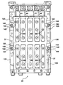
- FIG. 4 shows a pattern of insulating pads located on the inner walls of the mold half carriers
- FIG. 5 illustrates a cross-section of the mold half carrier and pad showing an insulating pad within a recess
- FIG. 6 illustrates an embodiment of the invention with the pads secured with the outer walls of the mold shell.
- the mold assembly described herein is adapted for making a hot fill PET bottle
- the mold apparatus shown can be used for cold fill operations as well as for the manufacture of other types of containers where the mold face is changed, such as for example, soft drinks, cleansers and detergent-type containers, to name a few.
- the mold half shell is made from stainless steel and the mold half carrier is made from aluminum.
- the mold half shells and the mold half carriers may be made from similar materials suitable for use in a mold assembly, such as for example, a stainless steel shell and carrier, or an aluminum shell and carrier.
- the mold assembly 10 is supported by a pair of support arms 12 which pivot about a pivot pin or axis 14 .
- a lever arm (not shown in figures) causes the support arms 12 to pivot about axis 14 to move the support arms 12 into the closed position shown.
- the support arms 12 support each of the two mold half carriers 20 .
- a first one of the mold half carriers 20 is fixedly secured to one of the support arms 12 by a threaded screw (not shown) or any other suitable connecting device.
- a second one of the mold half carriers 20 cooperates with a seat 13 on the other one of the supporting arms 12 .
- Spring-loaded bolts 18 pass through the support arm 12 and couple with the second carrier 20 .
- the bolts 18 bias the second carrier 20 into the seated engagement with the other supporting arm 12 by applying a pulling force to the second carrier 20 in the direction of the support arm 12 .
- the mold half carriers 20 each carry a modular mold half shell 22 .
- Modular mold half shells 22 define a cavity 24 whose shape determines the shape of the container formed in the cavity 24 .
- the support arms 12 hold the mold half carriers 20 and shells 22 in the closed position shown. While the detailed description relates to the use of modular mold half shells 22 , it should be understood that the present invention is applicable also for use with unitary mold half shells.
- a plastic preform 30 has a neck 26 and an elongated tubular portion 27 .
- the neck 26 is mounted to a molding machine (not shown) against the top surface 29 of the mold shells 22 with the tube portion 27 of the preform 30 extending into the cavity 24 of the mold shells 22 .
- Pressurized air is blown by a nozzle into neck 26 of preform 30 to expand tube 27 into the cavity 24 .
- the support arms 12 are pivoted about axis 14 to separate the carriers 20 and shells 22 to permit removal of the formed container and to permit interchanging of shells 22 from carriers 20 .
- the two modular mold half shells 22 each have an upper body mold section 42 and a lower body mold section 54 releasably secured to the upper body mold section 42 .
- the upper body mold section 42 has upper inner walls 44 defining an upper cavity 24 a whose dome shape corresponds to at least an upper portion of the container to be formed.
- the upper body mold section 42 has a first outer wall 36 that is in supported cooperation via insulating pads 80 with inner wall 37 of one of the carriers 20 .
- the lower body mold section 54 has body inner walls 37 defining a lower cavity 24 b that corresponds to at least a portion of the body of the container to be formed.
- the lower body mold section 54 has a second outer wall 39 also in supported cooperation via insulating pads 80 with the inner wall 37 of one of the carriers 20 . As best seen in FIGS. 4 and 5 , the insulating pads 80 extend from the carrier inner wall 37 for contacting the respective mold section outer walls 36 , 39 .
- each mold half shell 22 comprises top cavity inserts 40 which define an aperture or opening 41 through which the preform 30 may be inserted.
- the top cavity insert 40 forms a composite part of the upper body mold section 42 .
- the top cavity inserts 40 have third outer walls 43 which are also surrounded by the inner walls 37 of the carriers.
- the top cavity inserts 40 have a seating surface or face 45 .
- the seating face 45 is recessed in the top cavity inserts 40 and surrounds the aperture 41 .
- the seating surface 45 may alternatively be elevated or comprise several faces positioned on the same plane.
- the seating face 45 is adapted to receive the neck 26 of the preform 30 and positively locate the neck 26 against the seating face 45 .
- the upper body mold section 42 is further adapted to receive cavity insert 48 which has a convex shaped groove 52 that is formed in the container.
- the parting faces between the mold carriers 20 and the carrier shells 22 are shown in FIG. 2 for the mold carriers 20 at parting face 120 and for the mold half shells or modular half shells 22 at parting face 122 .
- the shells 22 are releasably secured within the carriers 20 by latches 140 .
- the latches 140 comprise tabs 142 that are rotated about locating bolts 144 mounted to the parting face 120 of the carriers 20 .
- the tabs 142 are rotated from a vertical position to a horizontal position across the parting face 122 of the shells 22 so as to secure the shells 122 within the cavity formed in the mold carriers 20 when bolts 144 are tightened.
- the modular mold shells 22 are shown to co-operate with a push up base 68 to define the base of the container to be formed.
- the base 68 rests upon base holder 70 which is mounted to pedestal 72 via a pedestal spacer 74 .
- the lower body mold section 54 Located below the upper body mold section 42 and forming part of the mold half shell 22 is the main lower body mold section 54 .
- the lower body mold section 54 has a lower surface 55 against which buts a shim mold section 58 .
- shim mold section 58 See U.S. Pat. No. 6,913,455, which is herein incorporated by reference.
- a bottom cavity insert 60 Positioned below the shim mold section 58 is a bottom cavity insert 60 .
- the bottom cavity insert 60 cooperates with the push up base 68 to define the bottom shape or contour of the container to be formed.
- a lower cavity insert 62 Located immediately below the ring 60 is a lower cavity insert 62 which is also mounted in butting relation on top of a wear ring 64 .
- the mold assembly 10 is utilized as a hot fill mold and comprises passageways or channels 78 provided at both the bottom and top of the shells 22 for supplying liquid, such as for example, oil, into the shells 22 to regulate the temperature of the mold half shells 22 .
- the passageways 78 at the bottom shells 22 pass into the body ring 62 and up through the mold half shells 22 and out through the upper passageways 78 mounted into the top cavity insert 40 .
- heated fluid under pressure passes through one of the passageways 78 and through the mold half shells 22 and out the other end of the mold half shells 22 so as to heat inner walls 44 , 37 of the upper body mold sections 42 and the lower body mold sections 54 .
- the insulating pads 80 are sized and spaced to provide uniform load distribution for supporting the mold half shells 22 .
- the pads 80 may also be sized and spaced for providing uniform thermal buffering between the shells 22 and each carrier inner wall 37 .
- the pads 80 are sandwiched between the inner walls 37 of each of the mold half carriers 20 and the outer walls 36 , 39 of the mold half shells 22 .
- the pads 80 support the outer walls 36 , 39 in a non-contacting and buffering relationship with the inner wall 37 . In the buffering relationship, the pads 80 buffer the inner walls 37 from the outer walls 36 , 39 to protect the inner walls 37 from thermal exposure, mechanical wear, or both, which may occur during operation of the mold assembly 10 .
- the pads 80 may absorb temperature differences or mechanical shock which may occur between the inner walls 37 and the outer walls 36 , 39 during operation of the assembly 10 .
- the pads 80 are secured with the inner walls 37 of the mold half carriers 20 and extend toward and abut the outer walls 36 , 39 of the mold shells 22 .
- the pads 80 provide a thermal insulative barrier between the mold half shells 22 and the mold half carriers 20 to reduce thermal conduction therebetween.
- the inner walls 37 of the mold half carriers 20 have recessed seats 81 corresponding to each pad 80 and within which the pads 80 may be secured.
- Each seat 81 has a depth 93 and each pad 80 has a thickness 91 .
- the thickness 91 exceeds the depth 93 of the recess 81 .
- each recessed seat 81 may be approximately 4 mm deep.
- the insulating pads 80 extend 1 mm out of the seats 81 to abut the mold shell outer walls 36 , 39 to space the mold shells 22 from the mold carriers 20 by a distance of 1 mm. It should be understood that the pads 80 may extend more or less than 1 mm out of the recessed seats 81 provided that the inner walls 37 are spaced from the outer walls 36 , 39 . Further, it should be understood that the inner walls 37 and outer walls 36 , 39 may be spaced without the use of recessed seats 81 , wherein the pads 80 may be secured to surface portions of the inner walls 37 .
- the pads 80 as shown in FIG.
- each open air space 85 provides a thermal air buffering zone 87 that reduces thermal conduction from the mold face through the shells 22 and out through the mold carriers 20 .
- the pads 80 are formed of a material that is dimensionally stable. That is, the material of the pads 80 does not expand more than the material of which the mold carriers 20 are made. This prevents interference between the pads 80 and the recesses 81 when the carrier 20 is heated during operation. Preferably, the material of the pads 80 does not expand when heated beyond the required tolerances of the system. Suitable materials include, but are not limited to, Phenolic-CE.
- the pads 80 may be fastened to the carrier walls 20 by any suitable means including the application of an adhesive, the use of clips, or fastening by screws passing through the pad 80 and into the respective inner wall 37 of the carrier 20 . In FIGS. 3 , 4 and 6 , the pads 80 are shown to be fastened into the recessed seats 81 by counter-sink screws 89 which pass through the pads 80 and into the respective seat 81 into which the pad 80 is to be secured.
- the pads 80 could be carried by the outer walls 36 , 39 of the mold half shells 22 , as shown in FIG. 6 .
- the insulating pads 80 have been shown to have a generally rectangular shape, it should be understood that the shape of the insulating pads 80 may be any suitable shape that provides the features of the present invention. Where a plurality of pads 80 are used, it is preferable that the pads 80 are distributed such that there is an even load on each pad 80 .
- pads 80 have been described as having a thickness 91 , it should be understood that pads 80 of a predetermined thickness 91 may be exchanged for pads 80 of a different thickness 91 in order to accommodate mold shells 22 of any diameter. Where it is desirable to use a mold shell 22 of a lesser diameter, pads 80 having a greater thickness 91 may be used. Where it is desirable to use a mold shell 22 of a greater diameter, pads 80 having a lesser thickness 91 may be used. In this way, the mold shell 22 may be changed while avoiding the need to change carrier 20 to suit the diameter of the new mold shell 22 .
Abstract
Description
Claims (20)
Priority Applications (2)
| Application Number | Priority Date | Filing Date | Title |
|---|---|---|---|
| US12/322,819 US8070470B2 (en) | 2009-02-06 | 2009-02-06 | Mold assembly |
| CA2690254A CA2690254C (en) | 2009-02-06 | 2010-01-14 | Mold assembly |
Applications Claiming Priority (1)
| Application Number | Priority Date | Filing Date | Title |
|---|---|---|---|
| US12/322,819 US8070470B2 (en) | 2009-02-06 | 2009-02-06 | Mold assembly |
Publications (2)
| Publication Number | Publication Date |
|---|---|
| US20100203186A1 US20100203186A1 (en) | 2010-08-12 |
| US8070470B2 true US8070470B2 (en) | 2011-12-06 |
Family
ID=42538213
Family Applications (1)
| Application Number | Title | Priority Date | Filing Date |
|---|---|---|---|
| US12/322,819 Expired - Fee Related US8070470B2 (en) | 2009-02-06 | 2009-02-06 | Mold assembly |
Country Status (2)
| Country | Link |
|---|---|
| US (1) | US8070470B2 (en) |
| CA (1) | CA2690254C (en) |
Cited By (3)
| Publication number | Priority date | Publication date | Assignee | Title |
|---|---|---|---|---|
| US20120052146A1 (en) * | 2010-08-26 | 2012-03-01 | Krones Ag | Blow Mold |
| US20120148703A1 (en) * | 2009-09-07 | 2012-06-14 | Sidel Participations | Molding device provided with a controlled means for clampingly attaching a half-mold by means of slidable attachment bolts |
| US20130043622A1 (en) * | 2011-08-19 | 2013-02-21 | Thomas Hoellriegl | Apparatus for shaping plastics material pre-forms into plastics material containers with pressure pads |
Families Citing this family (12)
| Publication number | Priority date | Publication date | Assignee | Title |
|---|---|---|---|---|
| DE102008007631A1 (en) * | 2008-02-04 | 2009-08-06 | Krones Ag | case shape |
| FR2930189B1 (en) * | 2008-04-21 | 2013-02-01 | Sidel Participations | DEVICE FOR MOLDING CONTAINERS COMPRISING MEANS FOR ADJUSTING THE VOLUMIC DIMENSIONS OF THE MOLDING CAVITY |
| FR2943268B1 (en) * | 2009-03-20 | 2014-02-28 | Arcil | THERMALLY INSULATING THERMOFROMING MOLD AND ASSOCIATED METHOD. |
| US9346585B2 (en) | 2010-10-01 | 2016-05-24 | Friendship Products Llc | Modular interlocking containers with enhanced lateral connectivity features |
| DE102011052863B4 (en) * | 2011-08-19 | 2022-12-22 | Krones Aktiengesellschaft | Device for forming plastic preforms into plastic containers and method for fastening blow molded parts to blow mold carrier shell parts |
| FR2982789B1 (en) * | 2011-11-22 | 2014-08-01 | Sidel Participations | THERMAL INSULATION DEVICE FOR MOLD, MOLD EQUIPPED WITH SUCH A DEVICE AND INSTALLATION COMPRISING AT LEAST ONE SUCH MOLD. |
| US9290300B2 (en) | 2012-02-21 | 2016-03-22 | Friendship Products Llc | Modular interlocking containers |
| CN103171129B (en) * | 2013-03-19 | 2015-03-25 | 江苏新美星包装机械股份有限公司 | Rapid die changing mechanism |
| FR3038541B1 (en) | 2015-07-08 | 2017-07-21 | Sidel Participations | MOLDING DEVICE FOR A MACHINE FOR MANUFACTURING THERMOPLASTIC CONTAINERS |
| FR3053906B1 (en) | 2016-12-12 | 2018-08-17 | Sidel Participations | MOLDING DEVICE FOR IMPLEMENTING HOT MOLDING AND COLD MOLDING PROCESSES |
| IT201700093124A1 (en) * | 2017-08-10 | 2019-02-10 | Orvim Srl | Collar and complementary parts made of composite materials and plastic materials for blow molding machines |
| DE102018126706A1 (en) * | 2018-10-25 | 2020-04-30 | Krones Ag | Blow molding device comprising a temperature control device |
Citations (41)
| Publication number | Priority date | Publication date | Assignee | Title |
|---|---|---|---|---|
| US170464A (en) | 1875-11-30 | Improvement in molds for glassware | ||
| US705772A (en) * | 1902-02-01 | 1902-07-29 | Lambert Company | Apparatus for reproducing phonograms. |
| US791240A (en) * | 1897-07-06 | 1905-05-30 | Claude Boucher | Manufacture of bottles, flasks, &c. |
| US3380121A (en) | 1965-07-30 | 1968-04-30 | American Can Co | Mold with replaceable inserts |
| US3768948A (en) | 1971-12-20 | 1973-10-30 | Monsanto Co | Blow mold |
| US3861640A (en) | 1973-05-21 | 1975-01-21 | Ideal Toy Corp | Interchangeable mold assembly |
| US3978910A (en) | 1975-07-07 | 1976-09-07 | Gladwin Floyd R | Mold plate cooling system |
| US4032278A (en) | 1976-03-02 | 1977-06-28 | Forest Mechanical Products Corporation | Sealing and shearing member in a plastic resin blow molding machine |
| US4151976A (en) | 1977-11-07 | 1979-05-01 | The Plastic Forming Company, Inc. | Modular die set for blow molding containers |
| USRE30215E (en) | 1976-03-02 | 1980-02-19 | Forest Mechanical Products Corp. | Sealing and shearing member in a plastic resin blow molding machine |
| US4330248A (en) | 1980-09-15 | 1982-05-18 | Platte Richard L | Mold with adjustable inserts |
| US4476170A (en) | 1982-03-03 | 1984-10-09 | Owens-Illinois, Inc. | Poly(ethylene terephthalate) articles and method |
| US4699585A (en) | 1984-09-28 | 1987-10-13 | Kautex-Werke Reinold Hagen Ag | Blow molding apparatus |
| JPS63202425A (en) | 1987-02-18 | 1988-08-22 | Toyo Seikan Kaisha Ltd | Manufacture of biaxially stretched polyester bottle |
| US4815960A (en) | 1985-05-06 | 1989-03-28 | Martin Rudolph | Blowing mould adjustable in longitudinal direction |
| US4822543A (en) | 1985-07-30 | 1989-04-18 | Yoshino Kogyosho Co., Ltd. | Method for forming plastic containers |
| US4863046A (en) | 1987-12-24 | 1989-09-05 | Continental Pet Technologies, Inc. | Hot fill container |
| US4884961A (en) | 1985-07-30 | 1989-12-05 | Yoshino Kogyosho Co., Ltd. | Apparatus for forming plastic containers |
| US4927680A (en) | 1987-12-24 | 1990-05-22 | Continental Pet Technologies, Inc. | Preform and method of forming container therefrom |
| GB2240300A (en) | 1990-01-24 | 1991-07-31 | Metal Box Plc | Blow mould having cooling channels |
| CA2082350A1 (en) | 1991-11-15 | 1993-05-16 | Wayne N. Collette | Modular mold |
| US5217729A (en) | 1990-03-22 | 1993-06-08 | Toppan Printing Co., Ltd. | Mold for plastic bottles |
| JPH08174552A (en) * | 1992-04-21 | 1996-07-09 | Hakko Denki Seisakusho:Kk | Low thermal mass mold apparatus |
| US5571474A (en) | 1991-09-14 | 1996-11-05 | Mauser-Werke Gmbh | Blow moulding machine |
| US5766299A (en) | 1996-11-04 | 1998-06-16 | Miller; Ronald P. | Mold for shaping glass |
| US5824237A (en) * | 1994-11-24 | 1998-10-20 | Tuhh Technologie Gmbh | Apparatus for manufacturing plastic articles |
| US5968560A (en) | 1995-04-19 | 1999-10-19 | Sidel | Blow molding device for producing thermoplastic containers |
| US6113377A (en) | 1995-08-22 | 2000-09-05 | Continental Pet Technologies, Inc. | Mould replacement and method of mould replacement in a blow moulding apparatus |
| CA2313881A1 (en) | 2000-07-14 | 2002-01-14 | Wentworth Mould Inc. | Universal blow mold assembly |
| US6413075B1 (en) | 1997-04-16 | 2002-07-02 | Husky Injection Molding Systems Ltd. | Partial crystallization apparatus of amorphous plastic articles |
| US6444159B2 (en) | 1999-05-04 | 2002-09-03 | Sidel, Inc. | Blow mold shell and shell assembly |
| US6447281B1 (en) | 1998-09-11 | 2002-09-10 | Sidel, Inc. | Blow mold shell and shell holder assembly for blow-molding machine |
| US6729868B1 (en) * | 1999-06-25 | 2004-05-04 | Klaus Vogel | Device for blow moulding containers |
| US20050006380A1 (en) * | 2003-07-02 | 2005-01-13 | Valery Kagan | Heating systems and methods |
| US6913455B2 (en) | 2003-04-11 | 2005-07-05 | Wentworth Mold Inc. | Hot fill mold shell assembly with reduced heat transfer |
| US6948924B2 (en) | 2003-04-11 | 2005-09-27 | Wentworth Mold Inc. | Mold assembly with modular mold shells |
| US6994542B2 (en) | 2003-12-30 | 2006-02-07 | Wentworth Mold Inc. | Air flow compensation for mold carrier |
| US7025584B2 (en) | 2003-08-29 | 2006-04-11 | Wentworth Mold Inc. | Mold base assembly |
| US7335007B2 (en) | 2005-04-18 | 2008-02-26 | Graham Packaging Company, L.P. | Quick change mold |
| US20090232929A1 (en) * | 2008-02-04 | 2009-09-17 | Erik Blochmann | Mould Housing |
| US20090263535A1 (en) * | 2008-04-21 | 2009-10-22 | Sidel Participations | Device for moulding containers comprising means of adjusting the volume dimensions of the moulding cavity |
-
2009
- 2009-02-06 US US12/322,819 patent/US8070470B2/en not_active Expired - Fee Related
-
2010
- 2010-01-14 CA CA2690254A patent/CA2690254C/en active Active
Patent Citations (45)
| Publication number | Priority date | Publication date | Assignee | Title |
|---|---|---|---|---|
| US170464A (en) | 1875-11-30 | Improvement in molds for glassware | ||
| US791240A (en) * | 1897-07-06 | 1905-05-30 | Claude Boucher | Manufacture of bottles, flasks, &c. |
| US705772A (en) * | 1902-02-01 | 1902-07-29 | Lambert Company | Apparatus for reproducing phonograms. |
| US3380121A (en) | 1965-07-30 | 1968-04-30 | American Can Co | Mold with replaceable inserts |
| US3768948A (en) | 1971-12-20 | 1973-10-30 | Monsanto Co | Blow mold |
| US3861640A (en) | 1973-05-21 | 1975-01-21 | Ideal Toy Corp | Interchangeable mold assembly |
| US3978910A (en) | 1975-07-07 | 1976-09-07 | Gladwin Floyd R | Mold plate cooling system |
| US4032278A (en) | 1976-03-02 | 1977-06-28 | Forest Mechanical Products Corporation | Sealing and shearing member in a plastic resin blow molding machine |
| USRE30215E (en) | 1976-03-02 | 1980-02-19 | Forest Mechanical Products Corp. | Sealing and shearing member in a plastic resin blow molding machine |
| US4151976A (en) | 1977-11-07 | 1979-05-01 | The Plastic Forming Company, Inc. | Modular die set for blow molding containers |
| US4330248A (en) | 1980-09-15 | 1982-05-18 | Platte Richard L | Mold with adjustable inserts |
| US4476170A (en) | 1982-03-03 | 1984-10-09 | Owens-Illinois, Inc. | Poly(ethylene terephthalate) articles and method |
| US4699585A (en) | 1984-09-28 | 1987-10-13 | Kautex-Werke Reinold Hagen Ag | Blow molding apparatus |
| US4815960A (en) | 1985-05-06 | 1989-03-28 | Martin Rudolph | Blowing mould adjustable in longitudinal direction |
| US4822543A (en) | 1985-07-30 | 1989-04-18 | Yoshino Kogyosho Co., Ltd. | Method for forming plastic containers |
| US4884961A (en) | 1985-07-30 | 1989-12-05 | Yoshino Kogyosho Co., Ltd. | Apparatus for forming plastic containers |
| JPS63202425A (en) | 1987-02-18 | 1988-08-22 | Toyo Seikan Kaisha Ltd | Manufacture of biaxially stretched polyester bottle |
| US4863046A (en) | 1987-12-24 | 1989-09-05 | Continental Pet Technologies, Inc. | Hot fill container |
| US4927680A (en) | 1987-12-24 | 1990-05-22 | Continental Pet Technologies, Inc. | Preform and method of forming container therefrom |
| GB2240300A (en) | 1990-01-24 | 1991-07-31 | Metal Box Plc | Blow mould having cooling channels |
| US5217729A (en) | 1990-03-22 | 1993-06-08 | Toppan Printing Co., Ltd. | Mold for plastic bottles |
| US5571474A (en) | 1991-09-14 | 1996-11-05 | Mauser-Werke Gmbh | Blow moulding machine |
| US5255889A (en) | 1991-11-15 | 1993-10-26 | Continental Pet Technologies, Inc. | Modular wold |
| US5411699A (en) | 1991-11-15 | 1995-05-02 | Continental Pet Technologies, Inc. | Modular mold |
| CA2082350A1 (en) | 1991-11-15 | 1993-05-16 | Wayne N. Collette | Modular mold |
| JPH08174552A (en) * | 1992-04-21 | 1996-07-09 | Hakko Denki Seisakusho:Kk | Low thermal mass mold apparatus |
| US5824237A (en) * | 1994-11-24 | 1998-10-20 | Tuhh Technologie Gmbh | Apparatus for manufacturing plastic articles |
| US5968560A (en) | 1995-04-19 | 1999-10-19 | Sidel | Blow molding device for producing thermoplastic containers |
| US6113377A (en) | 1995-08-22 | 2000-09-05 | Continental Pet Technologies, Inc. | Mould replacement and method of mould replacement in a blow moulding apparatus |
| US5766299A (en) | 1996-11-04 | 1998-06-16 | Miller; Ronald P. | Mold for shaping glass |
| US6413075B1 (en) | 1997-04-16 | 2002-07-02 | Husky Injection Molding Systems Ltd. | Partial crystallization apparatus of amorphous plastic articles |
| US6447281B1 (en) | 1998-09-11 | 2002-09-10 | Sidel, Inc. | Blow mold shell and shell holder assembly for blow-molding machine |
| US6444159B2 (en) | 1999-05-04 | 2002-09-03 | Sidel, Inc. | Blow mold shell and shell assembly |
| US6729868B1 (en) * | 1999-06-25 | 2004-05-04 | Klaus Vogel | Device for blow moulding containers |
| US6428302B1 (en) | 2000-07-14 | 2002-08-06 | Wentworth Mold Inc. | Universal blow mold assembly |
| CA2313881A1 (en) | 2000-07-14 | 2002-01-14 | Wentworth Mould Inc. | Universal blow mold assembly |
| US6913455B2 (en) | 2003-04-11 | 2005-07-05 | Wentworth Mold Inc. | Hot fill mold shell assembly with reduced heat transfer |
| US6948924B2 (en) | 2003-04-11 | 2005-09-27 | Wentworth Mold Inc. | Mold assembly with modular mold shells |
| US20050006380A1 (en) * | 2003-07-02 | 2005-01-13 | Valery Kagan | Heating systems and methods |
| US20060219709A1 (en) * | 2003-07-02 | 2006-10-05 | Itherm Technologies, Lp | Heating systems and methods |
| US7025584B2 (en) | 2003-08-29 | 2006-04-11 | Wentworth Mold Inc. | Mold base assembly |
| US6994542B2 (en) | 2003-12-30 | 2006-02-07 | Wentworth Mold Inc. | Air flow compensation for mold carrier |
| US7335007B2 (en) | 2005-04-18 | 2008-02-26 | Graham Packaging Company, L.P. | Quick change mold |
| US20090232929A1 (en) * | 2008-02-04 | 2009-09-17 | Erik Blochmann | Mould Housing |
| US20090263535A1 (en) * | 2008-04-21 | 2009-10-22 | Sidel Participations | Device for moulding containers comprising means of adjusting the volume dimensions of the moulding cavity |
Cited By (6)
| Publication number | Priority date | Publication date | Assignee | Title |
|---|---|---|---|---|
| US20120148703A1 (en) * | 2009-09-07 | 2012-06-14 | Sidel Participations | Molding device provided with a controlled means for clampingly attaching a half-mold by means of slidable attachment bolts |
| US8770961B2 (en) * | 2009-09-07 | 2014-07-08 | Sidel Participations | Molding device provided with a controlled means for clampingly attaching a half-mold by means of slidable attachment bolts |
| US20120052146A1 (en) * | 2010-08-26 | 2012-03-01 | Krones Ag | Blow Mold |
| US8641409B2 (en) * | 2010-08-26 | 2014-02-04 | Krones Ag | Blow mold |
| US20130043622A1 (en) * | 2011-08-19 | 2013-02-21 | Thomas Hoellriegl | Apparatus for shaping plastics material pre-forms into plastics material containers with pressure pads |
| US9044888B2 (en) * | 2011-08-19 | 2015-06-02 | Krones Ag | Apparatus for shaping plastics material pre-forms into plastics material containers with pressure pads |
Also Published As
| Publication number | Publication date |
|---|---|
| CA2690254C (en) | 2014-09-09 |
| CA2690254A1 (en) | 2010-08-06 |
| US20100203186A1 (en) | 2010-08-12 |
Similar Documents
| Publication | Publication Date | Title |
|---|---|---|
| US8070470B2 (en) | Mold assembly | |
| US6948924B2 (en) | Mold assembly with modular mold shells | |
| US6913455B2 (en) | Hot fill mold shell assembly with reduced heat transfer | |
| JP3500153B2 (en) | Equipment for manufacturing thermoplastic containers by blow molding or tension blow molding | |
| US20150375884A1 (en) | Systems, methods, and apparatuses for cooling hot-filled containers | |
| US20070237854A1 (en) | Hot runner system for injection molding machine | |
| JP6223501B2 (en) | Storage device for beverage containers | |
| US6428302B1 (en) | Universal blow mold assembly | |
| JPH07117112A (en) | Preform molding method in injection orientation blow molding | |
| US20140065256A1 (en) | Method for cooling a mould by circulating a heat-transfer fluid in contact with the external face thereof | |
| US20220152909A1 (en) | Blow molding tool for a blow molding machine | |
| US8354053B2 (en) | Blow moulding machine having a cooling device | |
| CA2525078C (en) | A gate cooling structure in a molding stack | |
| CA2438971C (en) | Mold base assembly | |
| US8226402B2 (en) | Mold for fabricating thermoplastic containers, and a blow-molding or stretch-blow molding installation equipped with such a mold | |
| US20110129558A1 (en) | Mould end-wall support for a blow-moulding machine, and blow-moulding machine comprising said end-wall support | |
| CA2538911C (en) | Heated blow mould for thermostabilizing treatment | |
| CN108215128B (en) | Molding device for carrying out hot and cold molding methods | |
| US8813462B2 (en) | Device and method for producing plastic containers and plastic containers produced by said method | |
| US10773447B2 (en) | Quick-change mandrel having active preform clamping | |
| US5700496A (en) | Self-adjusting mold backplate | |
| US20080118599A1 (en) | Mold with an Insert for a Container Blow Molding Machine | |
| KR101886391B1 (en) | Cooling and heating cup holder for vehicle | |
| BR0316129B1 (en) | installation for the manufacture of glass stoppers provided with a bottle capping head. | |
| US11667070B2 (en) | Device for producing containers by blow moulding |
Legal Events
| Date | Code | Title | Description |
|---|---|---|---|
| AS | Assignment |
Owner name: WENTWORTH MOLD LTD., CANADA Free format text: ASSIGNMENT OF ASSIGNORS INTEREST;ASSIGNORS:TSAU, TAR;KYI, KYI SAN;REEL/FRAME:022276/0434 Effective date: 20090203 |
|
| ZAAA | Notice of allowance and fees due |
Free format text: ORIGINAL CODE: NOA |
|
| ZAAB | Notice of allowance mailed |
Free format text: ORIGINAL CODE: MN/=. |
|
| STCF | Information on status: patent grant |
Free format text: PATENTED CASE |
|
| FPAY | Fee payment |
Year of fee payment: 4 |
|
| MAFP | Maintenance fee payment |
Free format text: PAYMENT OF MAINTENANCE FEE, 8TH YEAR, LARGE ENTITY (ORIGINAL EVENT CODE: M1552); ENTITY STATUS OF PATENT OWNER: LARGE ENTITY Year of fee payment: 8 |
|
| FEPP | Fee payment procedure |
Free format text: MAINTENANCE FEE REMINDER MAILED (ORIGINAL EVENT CODE: REM.); ENTITY STATUS OF PATENT OWNER: LARGE ENTITY |
|
| LAPS | Lapse for failure to pay maintenance fees |
Free format text: PATENT EXPIRED FOR FAILURE TO PAY MAINTENANCE FEES (ORIGINAL EVENT CODE: EXP.); ENTITY STATUS OF PATENT OWNER: LARGE ENTITY |
|
| STCH | Information on status: patent discontinuation |
Free format text: PATENT EXPIRED DUE TO NONPAYMENT OF MAINTENANCE FEES UNDER 37 CFR 1.362 |
|
| FP | Lapsed due to failure to pay maintenance fee |
Effective date: 20231206 |