EP2569212B1 - Track section with two lateral support members and method for producing a support member for such a track section - Google Patents
Track section with two lateral support members and method for producing a support member for such a track section Download PDFInfo
- Publication number
- EP2569212B1 EP2569212B1 EP10851487.8A EP10851487A EP2569212B1 EP 2569212 B1 EP2569212 B1 EP 2569212B1 EP 10851487 A EP10851487 A EP 10851487A EP 2569212 B1 EP2569212 B1 EP 2569212B1
- Authority
- EP
- European Patent Office
- Prior art keywords
- support member
- support
- track section
- stem part
- track
- Prior art date
- Legal status (The legal status is an assumption and is not a legal conclusion. Google has not performed a legal analysis and makes no representation as to the accuracy of the status listed.)
- Active
Links
Images


Classifications
-
- B—PERFORMING OPERATIONS; TRANSPORTING
- B62—LAND VEHICLES FOR TRAVELLING OTHERWISE THAN ON RAILS
- B62D—MOTOR VEHICLES; TRAILERS
- B62D55/00—Endless track vehicles
- B62D55/04—Endless track vehicles with tracks and alternative ground wheels, e.g. changeable from endless track vehicle into wheeled vehicle and vice versa
-
- B—PERFORMING OPERATIONS; TRANSPORTING
- B62—LAND VEHICLES FOR TRAVELLING OTHERWISE THAN ON RAILS
- B62D—MOTOR VEHICLES; TRAILERS
- B62D55/00—Endless track vehicles
- B62D55/08—Endless track units; Parts thereof
- B62D55/18—Tracks
- B62D55/20—Tracks of articulated type, e.g. chains
- B62D55/202—Wheel engaging parts; Wheel guides on links
Definitions
- the present invention relates to a track section according to the preamble of claim 1, which is adapted to be linked to a plurality of similar track sections to form a flexible track belt for mounting around the outer periphery of vehicle tyres.
- the invention also relates to a method for producing a support member for such a track section.
- Track belts which may be removably mounted around tyres of vehicles are known in several different designs. Such a track belt can be used in order to obtain better friction and traction between the vehicle tyres and the ground for a vehicle, particularly on wet, slippery or muddy terrain, or in order to increase the carrying capacity of a vehicle.
- a track section according to the preamble of claim 1 is previously known from WO 99/37525 A1 .
- the object of the present invention is to provide a track section of the above-mentioned type having a new and favourable design.
- the track section comprises a crossbar member and two lateral support members mounted to the crossbar member at opposite ends thereof, the support members protruding on the same side of the crossbar member and being spaced apart to allow a tyre to be received between the support members with the crossbar member extending across the envelope surface of the tyre and with the support members facing a respective one of the two opposed sidewalls of the tyre.
- Each support member has a first side facing the other support member and an opposite second side facing away from the other support member, a support surface being provided on said first side of the respective support member for engagement with the outer surface of a tyre received between the support members.
- At least one of the support members has an inner stem part, through which the support member is connected to the crossbar member, and an outer head part, which is connected to the stem part and which is wider than the stem part as seen in a direction corresponding to the longitudinal direction of the track belt.
- the support surface of said at least one support member bulges laterally in opposite directions at the part of the support member where the stem part meets the head part, so as to form a support surface section on the head part which is wider than an adjacent support surface section on the stem part as seen in said direction.
- a widened support surface section can be provided on the head part without increasing the width of the inner part of the support member through which the support member is connected to the crossbar member.
- An increased width of said inner part of the support member would give an increased width of the track section and thereby a larger distance between the crossbar members of the track belt formed by several interconnected track sections, which in its turn could reduce the efficiency of the track belt.
- the support member can be given an increased support surface area without increasing the width of the track section and without increasing the height of the support member.
- An increased support surface area will give an increased area of the contact surface between the support member and the tyre and thereby a reduced surface pressure on the tyre from the support member, which in its turn will reduce the wear on the tyre caused by the support member.
- said at least one support member is formed by deep drawing of a blank of steel sheet having a thickness of 6-12 mm, preferably 7-9 mm.
- the support member can be produced in a quick, simple and cost-effective manner.
- the invention also relates to a method for producing a support member for a track section, wherein a blank of steel sheet having a thickness of 6-12 mm, preferably 7-9 mm, is subjected to deep drawing so as to thereby form the support member.
- the support members can be produced in a quick, simple and cost-effective manner.
- the blank is heated before and/or during the deep drawing to a temperature of 900-1200°C.
- a temperature of 900-1200°C is heated before and/or during the deep drawing to a temperature of 900-1200°C.
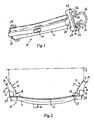
- a track section 10 according to an embodiment of the present invention is illustrated in Figs 1-3 .
- This track section 10 is to be linked to a plurality of similar track sections to form a flexible track belt 1 (see Fig 8 ) for mounting around the outer periphery of vehicle tyres.
- the track section 10 comprises an elongated crossbar member 11 and two lateral support members 12 mounted to the crossbar member 11 at opposite ends thereof.
- the crossbar member 11 has an essentially smooth inside 13 for engagement with the envelope surface 2 of a vehicle tyre 3.
- one or more gripping pegs 14 may be provided on the outside of the crossbar member 11, as illustrated in Figs 1 and 2 .
- the crossbar member 11 is formed by an elongated rigid beam having an essentially T-shaped cross-sectional shape.
- the crossbar member 11 may have any other suitable design.
- the support members 12 protrude on the inside 13 of the crossbar member 11.
- the support members 12 are spaced apart to allow a tyre 3 to be received between the support members 12 with the crossbar member 11 extending across the envelope surface 2 of the tyre 3 and with the support members 12 facing a respective one of the two opposed sidewalls 4 of the tyre, as illustrated in Fig 2 , where the lower part of a tyre 3 is illustrated in broken lines.
- Each support member 12 has a first side 15 facing the other support member and an opposite second side 16 facing away from the other support member.
- a support surface 17 is provided on said first side 15 of the respective support member for engagement with the outer surface of a tyre 3 received between the support members 12.
- the design of the support members 12 is shown in closer detail in Figs 4-7 .
- the respective support member 12 has an inner stem part 18, through which the support member 12 is connected to the crossbar member 11, and an outer head part 19, which is connected to the stem part 18 and which is wider than the stem part as seen in a direction D1 corresponding to the longitudinal direction of the track belt 1 to be formed by a number of interconnected track sections 10, i.e. the intended running direction of the track belt.
- This direction D1 is indicated by an arrow in Figs 4 and 6 .
- the support surface 17 of the support member bulges laterally in opposite directions at the part 20 of the support member where the stem part 18 meets the head part 19, so as to form a support surface section 17a on the head part 19 which is wider than an adjacent support surface section 17b on the stem part 18 as seen in said direction D1.
- the stem part 18 of the respective support member 12 has a U-shaped cross-sectional shape.
- the open side 21 of the stem part 18 faces away from the other support member, whereas the opposite closed side 22 faces the other support member.
- the stem part 18 has two essentially parallel lateral walls 23, 24 extending at a distance from each other and an intermediate wall 25 extending between the lateral walls on said closed side 22 of the stem part.
- the above-mentioned narrower support surface section 17b is provided on the intermediate wall 25.
- the head part 19 of the respective support member 12 is hood-shaped with an open side 26 facing away from the other support member and an opposite closed side 27 facing the other support member.
- the above-mentioned wider support surface section 17a is provided on said closed side 27.
- the respective support member 12 can be said to be scoop-shaped and has a rim 28 formed by the essentially straight edge 28a of the first lateral wall 23 of the stem part, the arc-shaped edge 28b of the head part 19 and the essentially straight edge 28c of the second lateral wall 23 of the stem part.
- the support surface 17 of the respective support member 12 is inclined away from the other support member as seen in the direction from the inner end of the support surface towards the outer end thereof, as illustrated in Figs 2 and 7 .
- the respective support member 12 is secured to an end of the crossbar member 11 through a C-shaped connection member 29, a so-called link hook, which is secured to the crossbar member 11 by welding.
- the stem part 18 of the support member 12 rests against a base part 30 of the connection member 29 through the inner edges of the lateral walls 23, 24 and is secured to this base part 30 by welding.
- a first end 31 of the connection member 29 is secured to a first lateral wall 23 of the stem part 18 by welding and the other end 32 of the connection member 29 is secured to the other lateral wall 24 of the stem part 18 by welding.
- a first opening 33 for receiving a first link element 35 is formed on a first side of the support member 12 between the first lateral wall 23 of the stem part 18 and the connection member 29 and a second opening 33 for receiving a second link element 35 is formed on the opposite side of the support member 12 between the other lateral wall 24 of the stem part 18 and the connection member 29.
- track sections 10 of the type described above are interconnected by means of link elements 35 to form a flexible track belt 1, as illustrated in Fig 8 .
- the respective link element 35 is received in an opening 33 of a connection member 29 of a first track section 10 and in an opening 33 of a connection member 29 of another adjacent track section 10.
- the link elements 35 will act as hinges between the track sections 10.
- the track section 1 is mounted around the outer periphery of two or more vehicle tyres 3 with the crossbar members 11 extending in the cross-direction of the tyres and with the support members 12 facing the tyres, as illustrated in Fig 8 .
- the support members 12 will keep the track belt 1 correctly positioned on the tyres 3 and will prevent the track belt 1 from slipping of the tyres 3.
- the opposed sidewalls 4 of the tyre will bulge due to the load from the vehicle and the sidewalls 4 will thereby come into contact with the support surfaces 17 of the two opposed support members 12 of a track section 10 received between the tyre 3 and the ground, as illustrated in Fig 2 .
- the respective support member 12 is formed by deep drawing of a blank 40 of steel sheet.
- the blank 40 is formed by being cut out from a steel sheet having a thickness of 6-12 mm, preferably 7-9 mm.
- the blank 40 is heated before and/or during the deep drawing to a temperature of 900-1200°C.
- a blank 40 having a thickness of 8 mm and heated to a temperature of approximately 950°C is placed on the upper end of a punch 41 with the edges of the blank resting against a lower die 42, as illustrated in Fig 9a .
- a holding member 43 is pressed against the upper surface of the blank 40 in order to keep the blank in place on the punch 41.
- an upper die 44 is pressed against the edges of the blank 40 and against the lower die 42 (see Fig 9b ) so as to shape the edges of the blank and give these edges a somewhat rounded shape.
- the lower die 42 is then lowered and moved away from the upper die, as illustrated in Fig 9c , whereupon the upper die 44 is moved downwards in relation to the punch 41 so as to subject the blank 40 to deep drawing for the final shaping of a support member 12 having the design described above. Thereafter, the upper die 44 and the holding member 43 are moved upwards away from the support member 12 and the punch 41, and the lower die 42 is moved upwards in relation to the punch 41 in order to push the support member 12 upwards and thereby release the support member 12 from the punch 41, as illustrated in Fig 9d .
- the support member 12 is finally quenched by being immersed in water or any other suitable quenching medium.
Landscapes
- Engineering & Computer Science (AREA)
- Chemical & Material Sciences (AREA)
- Combustion & Propulsion (AREA)
- Transportation (AREA)
- Mechanical Engineering (AREA)
- Tires In General (AREA)
- Chain Conveyers (AREA)
- Transmissions By Endless Flexible Members (AREA)
- Body Structure For Vehicles (AREA)
Description
- The present invention relates to a track section according to the preamble of claim 1, which is adapted to be linked to a plurality of similar track sections to form a flexible track belt for mounting around the outer periphery of vehicle tyres. The invention also relates to a method for producing a support member for such a track section.
- Track belts which may be removably mounted around tyres of vehicles are known in several different designs. Such a track belt can be used in order to obtain better friction and traction between the vehicle tyres and the ground for a vehicle, particularly on wet, slippery or muddy terrain, or in order to increase the carrying capacity of a vehicle.
- A track section according to the preamble of claim 1 is previously known from
WO 99/37525 A1 - The object of the present invention is to provide a track section of the above-mentioned type having a new and favourable design.
- According to the invention, said object is achieved by a track section having the features defined in claim 1.
- The track section according to the invention comprises a crossbar member and two lateral support members mounted to the crossbar member at opposite ends thereof, the support members protruding on the same side of the crossbar member and being spaced apart to allow a tyre to be received between the support members with the crossbar member extending across the envelope surface of the tyre and with the support members facing a respective one of the two opposed sidewalls of the tyre. Each support member has a first side facing the other support member and an opposite second side facing away from the other support member, a support surface being provided on said first side of the respective support member for engagement with the outer surface of a tyre received between the support members. At least one of the support members, preferably both of them, has an inner stem part, through which the support member is connected to the crossbar member, and an outer head part, which is connected to the stem part and which is wider than the stem part as seen in a direction corresponding to the longitudinal direction of the track belt. The support surface of said at least one support member bulges laterally in opposite directions at the part of the support member where the stem part meets the head part, so as to form a support surface section on the head part which is wider than an adjacent support surface section on the stem part as seen in said direction.
- Owing to the fact that the head part is wider than the stem part, a widened support surface section can be provided on the head part without increasing the width of the inner part of the support member through which the support member is connected to the crossbar member. An increased width of said inner part of the support member would give an increased width of the track section and thereby a larger distance between the crossbar members of the track belt formed by several interconnected track sections, which in its turn could reduce the efficiency of the track belt. With the solution according to the present invention, the support member can be given an increased support surface area without increasing the width of the track section and without increasing the height of the support member. An increased support surface area will give an increased area of the contact surface between the support member and the tyre and thereby a reduced surface pressure on the tyre from the support member, which in its turn will reduce the wear on the tyre caused by the support member.
- According to an embodiment of the invention, said at least one support member is formed by deep drawing of a blank of steel sheet having a thickness of 6-12 mm, preferably 7-9 mm. Hereby, the support member can be produced in a quick, simple and cost-effective manner.
- Further advantages as well as advantageous features of the track section according to the invention will appear from the following description and the dependent claims.
- The invention also relates to a method for producing a support member for a track section, wherein a blank of steel sheet having a thickness of 6-12 mm, preferably 7-9 mm, is subjected to deep drawing so as to thereby form the support member.
- With the method according to the invention, the support members can be produced in a quick, simple and cost-effective manner.
- According to an embodiment of the invention, the blank is heated before and/or during the deep drawing to a temperature of 900-1200°C. Hereby, the deep drawing of the blank is facilitated.
- Further advantages as well as advantageous features of the method according to the invention will appear from the following description and the dependent claims.
- With reference to the appended drawing, a specific description of preferred embodiments of the invention cited as examples follows below. In the drawings:
- Fig 1
- is a perspective view of a track section according to an embodiment of the present invention,
- Fig 2
- is a lateral view of the track section of
Fig 1 , - Fig 3
- shows a part of the track section of
Fig 1 , as seen from one end of the track section, - Fig 4
- is a perspective view of a support member included in the track section of
Fig 1 , - Fig 5
- is a perspective view of the support member of
Fig 4 , as seen from the rear side, - Fig 6
- is a rear view of the support member of
Fig 4 , - Fig 7
- is a lateral view of the support member of
Fig 4 , - Fig 8
- shows a part of a track belt formed of interconnected track sections of the type illustrated in
Figs 1-3 , with the track belt mounted around the outer periphery of vehicle tyres, and - Figs 9a-d
- schematically illustrates different steps in a method for producing a support member of the type illustrated in
Figs 4-7 . - A
track section 10 according to an embodiment of the present invention is illustrated inFigs 1-3 . Thistrack section 10 is to be linked to a plurality of similar track sections to form a flexible track belt 1 (seeFig 8 ) for mounting around the outer periphery of vehicle tyres. Thetrack section 10 comprises anelongated crossbar member 11 and twolateral support members 12 mounted to thecrossbar member 11 at opposite ends thereof. - The
crossbar member 11 has an essentially smooth inside 13 for engagement with theenvelope surface 2 of avehicle tyre 3. In order to improve the grip against the ground, one or moregripping pegs 14 may be provided on the outside of thecrossbar member 11, as illustrated inFigs 1 and 2 . In the illustrated embodiment, thecrossbar member 11 is formed by an elongated rigid beam having an essentially T-shaped cross-sectional shape. However, thecrossbar member 11 may have any other suitable design. - The
support members 12 protrude on theinside 13 of thecrossbar member 11. Thesupport members 12 are spaced apart to allow atyre 3 to be received between thesupport members 12 with thecrossbar member 11 extending across theenvelope surface 2 of thetyre 3 and with thesupport members 12 facing a respective one of the two opposed sidewalls 4 of the tyre, as illustrated inFig 2 , where the lower part of atyre 3 is illustrated in broken lines. Eachsupport member 12 has afirst side 15 facing the other support member and an oppositesecond side 16 facing away from the other support member. Asupport surface 17 is provided on saidfirst side 15 of the respective support member for engagement with the outer surface of atyre 3 received between thesupport members 12. - The design of the
support members 12 is shown in closer detail inFigs 4-7 . Therespective support member 12 has aninner stem part 18, through which thesupport member 12 is connected to thecrossbar member 11, and anouter head part 19, which is connected to thestem part 18 and which is wider than the stem part as seen in a direction D1 corresponding to the longitudinal direction of the track belt 1 to be formed by a number of interconnectedtrack sections 10, i.e. the intended running direction of the track belt. This direction D1 is indicated by an arrow inFigs 4 and6 . Thesupport surface 17 of the support member bulges laterally in opposite directions at thepart 20 of the support member where thestem part 18 meets thehead part 19, so as to form asupport surface section 17a on thehead part 19 which is wider than an adjacent support surface section 17b on thestem part 18 as seen in said direction D1. - The
stem part 18 of therespective support member 12 has a U-shaped cross-sectional shape. Theopen side 21 of thestem part 18 faces away from the other support member, whereas the opposite closedside 22 faces the other support member. Thestem part 18 has two essentially parallellateral walls intermediate wall 25 extending between the lateral walls on said closedside 22 of the stem part. The above-mentioned narrower support surface section 17b is provided on theintermediate wall 25. - The
head part 19 of therespective support member 12 is hood-shaped with anopen side 26 facing away from the other support member and an oppositeclosed side 27 facing the other support member. The above-mentioned widersupport surface section 17a is provided on saidclosed side 27. - The
respective support member 12 can be said to be scoop-shaped and has arim 28 formed by the essentiallystraight edge 28a of the firstlateral wall 23 of the stem part, the arc-shaped edge 28b of thehead part 19 and the essentially straight edge 28c of the secondlateral wall 23 of the stem part. - The
support surface 17 of therespective support member 12 is inclined away from the other support member as seen in the direction from the inner end of the support surface towards the outer end thereof, as illustrated inFigs 2 and7 . - In the illustrated example, the
respective support member 12 is secured to an end of thecrossbar member 11 through a C-shapedconnection member 29, a so-called link hook, which is secured to thecrossbar member 11 by welding. Thestem part 18 of thesupport member 12 rests against abase part 30 of theconnection member 29 through the inner edges of thelateral walls base part 30 by welding. Afirst end 31 of theconnection member 29 is secured to a firstlateral wall 23 of thestem part 18 by welding and theother end 32 of theconnection member 29 is secured to the otherlateral wall 24 of thestem part 18 by welding. Hereby, afirst opening 33 for receiving afirst link element 35 is formed on a first side of thesupport member 12 between the firstlateral wall 23 of thestem part 18 and theconnection member 29 and asecond opening 33 for receiving asecond link element 35 is formed on the opposite side of thesupport member 12 between the otherlateral wall 24 of thestem part 18 and theconnection member 29. -
Several track sections 10 of the type described above are interconnected by means oflink elements 35 to form a flexible track belt 1, as illustrated inFig 8 . Therespective link element 35 is received in anopening 33 of aconnection member 29 of afirst track section 10 and in anopening 33 of aconnection member 29 of anotheradjacent track section 10. Thelink elements 35 will act as hinges between thetrack sections 10. The track section 1 is mounted around the outer periphery of two ormore vehicle tyres 3 with thecrossbar members 11 extending in the cross-direction of the tyres and with thesupport members 12 facing the tyres, as illustrated inFig 8 . Thesupport members 12 will keep the track belt 1 correctly positioned on thetyres 3 and will prevent the track belt 1 from slipping of thetyres 3. At the part of atyre 3 that bears against the ground, the opposed sidewalls 4 of the tyre will bulge due to the load from the vehicle and the sidewalls 4 will thereby come into contact with the support surfaces 17 of the twoopposed support members 12 of atrack section 10 received between thetyre 3 and the ground, as illustrated inFig 2 . - The
respective support member 12 is formed by deep drawing of a blank 40 of steel sheet. The blank 40 is formed by being cut out from a steel sheet having a thickness of 6-12 mm, preferably 7-9 mm. The blank 40 is heated before and/or during the deep drawing to a temperature of 900-1200°C. - Different steps in a deep drawing process for forming a
support member 12 of the type described above are illustrated inFigs 9a-9d . In a first step, a blank 40 having a thickness of 8 mm and heated to a temperature of approximately 950°C is placed on the upper end of apunch 41 with the edges of the blank resting against alower die 42, as illustrated inFig 9a . A holdingmember 43 is pressed against the upper surface of the blank 40 in order to keep the blank in place on thepunch 41. Thereafter, anupper die 44 is pressed against the edges of the blank 40 and against the lower die 42 (seeFig 9b ) so as to shape the edges of the blank and give these edges a somewhat rounded shape. Thelower die 42 is then lowered and moved away from the upper die, as illustrated inFig 9c , whereupon theupper die 44 is moved downwards in relation to thepunch 41 so as to subject the blank 40 to deep drawing for the final shaping of asupport member 12 having the design described above. Thereafter, theupper die 44 and the holdingmember 43 are moved upwards away from thesupport member 12 and thepunch 41, and thelower die 42 is moved upwards in relation to thepunch 41 in order to push thesupport member 12 upwards and thereby release thesupport member 12 from thepunch 41, as illustrated inFig 9d . Thesupport member 12 is finally quenched by being immersed in water or any other suitable quenching medium. - The invention is of course not in any way restricted to the embodiments described above. On the contrary, many possibilities to modifications thereof will be apparent to a person with ordinary skill in the art without departing from the basic idea of the invention such as defined in the appended claims.
Claims (10)
- A track section adapted to be linked to a plurality of similar track sections to form a flexible track belt for mounting around the outer periphery of vehicle tyres, wherein the track section comprises a crossbar member (11) and two lateral support members (12) mounted to the crossbar member (11) at opposite ends thereof, the support members (12) protruding on the same side of the crossbar member (11) and being spaced apart to allow a tyre to be received between the support members (12) with the crossbar member (11) extending across the envelope surface of the tyre and with the support members (12) facing a respective one of the two opposed sidewalls of the tyre, each support member (12) having a first side (15) facing the other support member and an opposite second side (16) facing away from the other support member, a support surface (17) being provided on said first side (15) of the respective support member for engagement with the outer surface of a tyre received between the support members,
characterized in:- that at least one of the support members (12), preferably both of them, has an inner stem part (18), through which the support member (12) is connected to the crossbar member (11), and an outer head part (19), which is connected to the stem part (18) and which is wider than the stem part as seen in a direction (D1) corresponding to the longitudinal direction of the track belt; and- that the support surface (17) of said at least one support member bulges laterally in opposite directions at the part of the support member where the stem part (18) meets the head part (19), so as to form a support surface section (17a) on the head part (19) which is wider than an adjacent support surface section (17b) on the stem part (18) as seen in said direction (D1). - A track section according to claim 1, characterized in, that the stem part (18) of said at least one support member has a U-shaped cross-sectional shape, the open side (21) of the stem part (18) facing away from the other support member and the opposite closed side (22) of the stem part facing the other support member.
- A track section according to claim 2, characterized in, that the stem part (18) has two essentially parallel lateral walls (23, 24) extending at a distance from each other and an intermediate wall (25) extending between the lateral walls on said closed side (22) of the stem part, said narrower support surface section (17b) being provided on this intermediate wall (25).
- A track section according to any of claims 1-3, characterized in, that the head part (19) of said at least one support member is hood-shaped with an open side (26) facing away from the other support member and an opposite closed side (27) facing the other support member, said wider support surface section (17a) being provided on this closed side (27).
- A track section according to any of claims 1-4, characterized in that the support surface (17) of said at least one support member is inclined away from the other support member as seen in the direction from the inner end of the support surface towards the outer end thereof.
- A track section according to any of claims 1-5, characterized in that said at least one support member (12) is formed by deep drawing of a blank of steel sheet having a thickness of 6-12 mm, preferably 7-9 mm.
- A method for producing a support member for a track section according to any of claims 1-6, characterized in that a blank (40) of steel sheet having a thickness of 6-12 mm, preferably 7-9 mm, is subjected to deep drawing so as to thereby form the support member (12).
- A method according to claim 7, characterized in that the blank (40) is cut out from a steel sheet having a thickness of 6-12 mm, preferably 7-9 mm.
- A method according to claim 7 or 8, characterized in that the blank (40) is heated before and/or during the deep drawing to a temperature of 900-1200°C.
- A method according to claim 9, characterized in that the formed support member (12) is quenched by being immersed in a quenching medium.
Applications Claiming Priority (1)
| Application Number | Priority Date | Filing Date | Title |
|---|---|---|---|
| PCT/SE2010/050524 WO2011142701A1 (en) | 2010-05-12 | 2010-05-12 | Track section with two lateral support members and method for producing a support member for such a track section |
Publications (3)
| Publication Number | Publication Date |
|---|---|
| EP2569212A1 EP2569212A1 (en) | 2013-03-20 |
| EP2569212A4 EP2569212A4 (en) | 2013-10-02 |
| EP2569212B1 true EP2569212B1 (en) | 2014-09-03 |
Family
ID=44914578
Family Applications (1)
| Application Number | Title | Priority Date | Filing Date |
|---|---|---|---|
| EP10851487.8A Active EP2569212B1 (en) | 2010-05-12 | 2010-05-12 | Track section with two lateral support members and method for producing a support member for such a track section |
Country Status (5)
| Country | Link |
|---|---|
| EP (1) | EP2569212B1 (en) |
| BR (1) | BR112012028845B1 (en) |
| CA (1) | CA2798977C (en) |
| RU (1) | RU2530947C2 (en) |
| WO (1) | WO2011142701A1 (en) |
Cited By (2)
| Publication number | Priority date | Publication date | Assignee | Title |
|---|---|---|---|---|
| EP3539853A1 (en) * | 2018-02-16 | 2019-09-18 | Saramoto Oy | Machine track system |
| US11560189B2 (en) * | 2017-05-23 | 2023-01-24 | Chee Kong Wong | Track elements for forming a continuous over tyre track with strength enhancement structure |
Families Citing this family (15)
| Publication number | Priority date | Publication date | Assignee | Title |
|---|---|---|---|---|
| DE102012102231A1 (en) | 2012-03-16 | 2013-09-19 | Erlau Ag | Anti-skid chain with side-stable guide chains |
| DE202014103179U1 (en) | 2014-07-10 | 2014-07-30 | Erlau Ag | Plate band element for serving as a traction aid, plate-band-shaped track for twin axes |
| RU174836U1 (en) * | 2016-10-03 | 2017-11-07 | Иван Евгеньевич Игнатьев | TRACK TAPE |
| RU2631964C1 (en) * | 2016-10-03 | 2017-09-29 | Иван Евгеньевич Игнатьев | Caterpillar track |
| BR112020001267A2 (en) * | 2017-07-21 | 2020-07-21 | Fomatec Oy | vehicle track set for all types of terrain and track repair method |
| RU183191U1 (en) * | 2018-01-26 | 2018-09-13 | Андрей Юрьевич Козин | CRAWLER CHAIN LINK |
| RU183552U1 (en) * | 2018-01-26 | 2018-09-25 | Андрей Юрьевич Козин | CRAWLER CHAIN LINK |
| RU183545U1 (en) * | 2018-01-26 | 2018-09-25 | Андрей Юрьевич Козин | VEHICLE CRAWLER CHAIN |
| LT3560802T (en) * | 2018-04-27 | 2022-08-10 | Olofsfors Ab | Track section with crossbar member and track belt formed by such track sections |
| RU184521U1 (en) * | 2018-05-11 | 2018-10-30 | Владимир Николаевич Заварзин | TRACK VEHICLE DRIVE |
| CA183478S (en) | 2018-09-12 | 2019-07-05 | Quality Chain Canada Ltd | Tire pad |
| RU192895U1 (en) * | 2019-02-11 | 2019-10-04 | Андрей Юрьевич Козин | CRAWLER CHAIN LINK |
| EP3798107B1 (en) | 2019-09-30 | 2022-02-23 | Olofsfors AB | Track section with crossbar and track belt formed by such track sections |
| RU209237U1 (en) * | 2021-11-12 | 2022-02-08 | Общество с ограниченной ответственностью «КМЗ» | Vehicle track chain |
| EP4438446A1 (en) * | 2023-03-30 | 2024-10-02 | Nordic Traction Oy | Side guide assembly and forest machine track |
Family Cites Families (6)
| Publication number | Priority date | Publication date | Assignee | Title |
|---|---|---|---|---|
| US2764212A (en) * | 1953-01-09 | 1956-09-25 | Gen Motors Corp | Tire track with driving points |
| CA1215735A (en) * | 1984-08-29 | 1986-12-23 | Ontario Drive And Gear Limited | Tire-located track |
| SU1652170A1 (en) * | 1989-05-29 | 1991-05-30 | Всесоюзный научно-исследовательский институт торфяной промышленности | Detachable tracked running gear of vehicle |
| US5429429A (en) * | 1992-08-28 | 1995-07-04 | Loegering; George A. | Track bolster for a track section of a removable flexible track belt |
| SE513659C2 (en) * | 1998-01-07 | 2000-10-16 | Olofsfors Ab | belt assembly |
| US6267453B1 (en) * | 1999-11-12 | 2001-07-31 | Soucy International Inc. | Endless track with debris evacuation side outlets |
-
2010
- 2010-05-12 BR BR112012028845-8A patent/BR112012028845B1/en active IP Right Grant
- 2010-05-12 CA CA2798977A patent/CA2798977C/en active Active
- 2010-05-12 RU RU2012153569/11A patent/RU2530947C2/en active
- 2010-05-12 EP EP10851487.8A patent/EP2569212B1/en active Active
- 2010-05-12 WO PCT/SE2010/050524 patent/WO2011142701A1/en not_active Ceased
Cited By (2)
| Publication number | Priority date | Publication date | Assignee | Title |
|---|---|---|---|---|
| US11560189B2 (en) * | 2017-05-23 | 2023-01-24 | Chee Kong Wong | Track elements for forming a continuous over tyre track with strength enhancement structure |
| EP3539853A1 (en) * | 2018-02-16 | 2019-09-18 | Saramoto Oy | Machine track system |
Also Published As
| Publication number | Publication date |
|---|---|
| BR112012028845B1 (en) | 2020-06-30 |
| RU2530947C2 (en) | 2014-10-20 |
| WO2011142701A1 (en) | 2011-11-17 |
| EP2569212A1 (en) | 2013-03-20 |
| EP2569212A4 (en) | 2013-10-02 |
| BR112012028845A2 (en) | 2016-07-26 |
| CA2798977A1 (en) | 2011-11-17 |
| RU2012153569A (en) | 2014-06-20 |
| CA2798977C (en) | 2017-07-18 |
Similar Documents
| Publication | Publication Date | Title |
|---|---|---|
| EP2569212B1 (en) | Track section with two lateral support members and method for producing a support member for such a track section | |
| JP4860889B2 (en) | Chain transmission device for chain, chain wheel and hoisting device | |
| EP1752319B1 (en) | Snow chain with portions of twisted links | |
| JP7232335B2 (en) | Metal web for non-pneumatic tires and method of making same | |
| US9950581B2 (en) | Anti-skid chain having laterally stable guiding chains | |
| EP3560802B1 (en) | Track section with crossbar member and track belt formed by such track sections | |
| CA3041292A1 (en) | Profiled bar, and vehicles spring produced therefrom | |
| EP3798107A1 (en) | Track section with crossbar and track belt formed by such track sections | |
| WO2005068263A1 (en) | Bumper and a method of manufacturing the same | |
| RU192895U1 (en) | CRAWLER CHAIN LINK | |
| RU2811783C1 (en) | Track section with cross member and track band formed by such track sections | |
| US20210356017A1 (en) | Drive chain and method for manufacturing a drive-chain | |
| RU2820723C1 (en) | Method of manufacturing connecting element of caterpillar link with inserts, connecting element, insert intended for use in connecting element, caterpillar chain link with such connecting elements and caterpillar chain formed by these links | |
| EP3260315B2 (en) | Chain track | |
| CN218702512U (en) | Forged wheel | |
| KR101478743B1 (en) | Snow chain of spike-link type and Mounting apparatus thereof | |
| EP1757515B1 (en) | Drive roll and auxiliary drive means provided with a drive roll of this type | |
| CA2808115A1 (en) | Chain for mounting on a vehicle tire | |
| US4297959A (en) | Method for making chain bracket with strengthened chain supports | |
| US5402838A (en) | Tire traction apparatus | |
| CN205970626U (en) | Preforming formula wheel hub | |
| CN210082834U (en) | Hook type composite material annular rubber chain plate belt ply | |
| JP3064252U (en) | Groove lid | |
| KR200259424Y1 (en) | Snow Chain | |
| ITUD950134A1 (en) | SYSTEM COMPOSED OF TWO HALF CIRCLES THAT CAN BE HOOKED BETWEEN THEM THAT SUPPORT FOUR PAIRS OF HOOKS, IT IS APPLIED ON THE WHEELS |
Legal Events
| Date | Code | Title | Description |
|---|---|---|---|
| PUAI | Public reference made under article 153(3) epc to a published international application that has entered the european phase |
Free format text: ORIGINAL CODE: 0009012 |
|
| 17P | Request for examination filed |
Effective date: 20121018 |
|
| AK | Designated contracting states |
Kind code of ref document: A1 Designated state(s): AL AT BE BG CH CY CZ DE DK EE ES FI FR GB GR HR HU IE IS IT LI LT LU LV MC MK MT NL NO PL PT RO SE SI SK SM TR |
|
| DAX | Request for extension of the european patent (deleted) | ||
| A4 | Supplementary search report drawn up and despatched |
Effective date: 20130902 |
|
| RIC1 | Information provided on ipc code assigned before grant |
Ipc: B62D 55/04 20060101AFI20130827BHEP Ipc: B62D 55/20 20060101ALI20130827BHEP |
|
| GRAP | Despatch of communication of intention to grant a patent |
Free format text: ORIGINAL CODE: EPIDOSNIGR1 |
|
| INTG | Intention to grant announced |
Effective date: 20140328 |
|
| GRAS | Grant fee paid |
Free format text: ORIGINAL CODE: EPIDOSNIGR3 |
|
| GRAA | (expected) grant |
Free format text: ORIGINAL CODE: 0009210 |
|
| AK | Designated contracting states |
Kind code of ref document: B1 Designated state(s): AL AT BE BG CH CY CZ DE DK EE ES FI FR GB GR HR HU IE IS IT LI LT LU LV MC MK MT NL NO PL PT RO SE SI SK SM TR |
|
| REG | Reference to a national code |
Ref country code: GB Ref legal event code: FG4D |
|
| REG | Reference to a national code |
Ref country code: AT Ref legal event code: REF Ref document number: 685423 Country of ref document: AT Kind code of ref document: T Effective date: 20140915 Ref country code: CH Ref legal event code: EP |
|
| REG | Reference to a national code |
Ref country code: IE Ref legal event code: FG4D |
|
| REG | Reference to a national code |
Ref country code: DE Ref legal event code: R096 Ref document number: 602010018813 Country of ref document: DE Effective date: 20141016 |
|
| REG | Reference to a national code |
Ref country code: SE Ref legal event code: TRGR |
|
| REG | Reference to a national code |
Ref country code: AT Ref legal event code: MK05 Ref document number: 685423 Country of ref document: AT Kind code of ref document: T Effective date: 20140903 |
|
| PG25 | Lapsed in a contracting state [announced via postgrant information from national office to epo] |
Ref country code: GR Free format text: LAPSE BECAUSE OF FAILURE TO SUBMIT A TRANSLATION OF THE DESCRIPTION OR TO PAY THE FEE WITHIN THE PRESCRIBED TIME-LIMIT Effective date: 20141204 Ref country code: LT Free format text: LAPSE BECAUSE OF FAILURE TO SUBMIT A TRANSLATION OF THE DESCRIPTION OR TO PAY THE FEE WITHIN THE PRESCRIBED TIME-LIMIT Effective date: 20140903 Ref country code: ES Free format text: LAPSE BECAUSE OF FAILURE TO SUBMIT A TRANSLATION OF THE DESCRIPTION OR TO PAY THE FEE WITHIN THE PRESCRIBED TIME-LIMIT Effective date: 20140903 Ref country code: NO Free format text: LAPSE BECAUSE OF FAILURE TO SUBMIT A TRANSLATION OF THE DESCRIPTION OR TO PAY THE FEE WITHIN THE PRESCRIBED TIME-LIMIT Effective date: 20141203 |
|
| REG | Reference to a national code |
Ref country code: NL Ref legal event code: VDEP Effective date: 20140903 |
|
| REG | Reference to a national code |
Ref country code: LT Ref legal event code: MG4D |
|
| PG25 | Lapsed in a contracting state [announced via postgrant information from national office to epo] |
Ref country code: LV Free format text: LAPSE BECAUSE OF FAILURE TO SUBMIT A TRANSLATION OF THE DESCRIPTION OR TO PAY THE FEE WITHIN THE PRESCRIBED TIME-LIMIT Effective date: 20140903 Ref country code: HR Free format text: LAPSE BECAUSE OF FAILURE TO SUBMIT A TRANSLATION OF THE DESCRIPTION OR TO PAY THE FEE WITHIN THE PRESCRIBED TIME-LIMIT Effective date: 20140903 Ref country code: AT Free format text: LAPSE BECAUSE OF FAILURE TO SUBMIT A TRANSLATION OF THE DESCRIPTION OR TO PAY THE FEE WITHIN THE PRESCRIBED TIME-LIMIT Effective date: 20140903 Ref country code: CY Free format text: LAPSE BECAUSE OF FAILURE TO SUBMIT A TRANSLATION OF THE DESCRIPTION OR TO PAY THE FEE WITHIN THE PRESCRIBED TIME-LIMIT Effective date: 20140903 |
|
| PG25 | Lapsed in a contracting state [announced via postgrant information from national office to epo] |
Ref country code: NL Free format text: LAPSE BECAUSE OF FAILURE TO SUBMIT A TRANSLATION OF THE DESCRIPTION OR TO PAY THE FEE WITHIN THE PRESCRIBED TIME-LIMIT Effective date: 20140903 |
|
| PG25 | Lapsed in a contracting state [announced via postgrant information from national office to epo] |
Ref country code: PT Free format text: LAPSE BECAUSE OF FAILURE TO SUBMIT A TRANSLATION OF THE DESCRIPTION OR TO PAY THE FEE WITHIN THE PRESCRIBED TIME-LIMIT Effective date: 20150105 Ref country code: RO Free format text: LAPSE BECAUSE OF FAILURE TO SUBMIT A TRANSLATION OF THE DESCRIPTION OR TO PAY THE FEE WITHIN THE PRESCRIBED TIME-LIMIT Effective date: 20140903 Ref country code: IS Free format text: LAPSE BECAUSE OF FAILURE TO SUBMIT A TRANSLATION OF THE DESCRIPTION OR TO PAY THE FEE WITHIN THE PRESCRIBED TIME-LIMIT Effective date: 20150103 Ref country code: CZ Free format text: LAPSE BECAUSE OF FAILURE TO SUBMIT A TRANSLATION OF THE DESCRIPTION OR TO PAY THE FEE WITHIN THE PRESCRIBED TIME-LIMIT Effective date: 20140903 Ref country code: SK Free format text: LAPSE BECAUSE OF FAILURE TO SUBMIT A TRANSLATION OF THE DESCRIPTION OR TO PAY THE FEE WITHIN THE PRESCRIBED TIME-LIMIT Effective date: 20140903 Ref country code: EE Free format text: LAPSE BECAUSE OF FAILURE TO SUBMIT A TRANSLATION OF THE DESCRIPTION OR TO PAY THE FEE WITHIN THE PRESCRIBED TIME-LIMIT Effective date: 20140903 |
|
| PG25 | Lapsed in a contracting state [announced via postgrant information from national office to epo] |
Ref country code: PL Free format text: LAPSE BECAUSE OF FAILURE TO SUBMIT A TRANSLATION OF THE DESCRIPTION OR TO PAY THE FEE WITHIN THE PRESCRIBED TIME-LIMIT Effective date: 20140903 |
|
| REG | Reference to a national code |
Ref country code: DE Ref legal event code: R097 Ref document number: 602010018813 Country of ref document: DE |
|
| PLBE | No opposition filed within time limit |
Free format text: ORIGINAL CODE: 0009261 |
|
| STAA | Information on the status of an ep patent application or granted ep patent |
Free format text: STATUS: NO OPPOSITION FILED WITHIN TIME LIMIT |
|
| PG25 | Lapsed in a contracting state [announced via postgrant information from national office to epo] |
Ref country code: DK Free format text: LAPSE BECAUSE OF FAILURE TO SUBMIT A TRANSLATION OF THE DESCRIPTION OR TO PAY THE FEE WITHIN THE PRESCRIBED TIME-LIMIT Effective date: 20140903 |
|
| 26N | No opposition filed |
Effective date: 20150604 |
|
| PG25 | Lapsed in a contracting state [announced via postgrant information from national office to epo] |
Ref country code: IT Free format text: LAPSE BECAUSE OF FAILURE TO SUBMIT A TRANSLATION OF THE DESCRIPTION OR TO PAY THE FEE WITHIN THE PRESCRIBED TIME-LIMIT Effective date: 20140903 |
|
| PG25 | Lapsed in a contracting state [announced via postgrant information from national office to epo] |
Ref country code: SI Free format text: LAPSE BECAUSE OF FAILURE TO SUBMIT A TRANSLATION OF THE DESCRIPTION OR TO PAY THE FEE WITHIN THE PRESCRIBED TIME-LIMIT Effective date: 20140903 |
|
| REG | Reference to a national code |
Ref country code: DE Ref legal event code: R119 Ref document number: 602010018813 Country of ref document: DE |
|
| REG | Reference to a national code |
Ref country code: CH Ref legal event code: PL |
|
| PG25 | Lapsed in a contracting state [announced via postgrant information from national office to epo] |
Ref country code: MC Free format text: LAPSE BECAUSE OF FAILURE TO SUBMIT A TRANSLATION OF THE DESCRIPTION OR TO PAY THE FEE WITHIN THE PRESCRIBED TIME-LIMIT Effective date: 20140903 Ref country code: LI Free format text: LAPSE BECAUSE OF NON-PAYMENT OF DUE FEES Effective date: 20150531 Ref country code: LU Free format text: LAPSE BECAUSE OF FAILURE TO SUBMIT A TRANSLATION OF THE DESCRIPTION OR TO PAY THE FEE WITHIN THE PRESCRIBED TIME-LIMIT Effective date: 20150512 Ref country code: CH Free format text: LAPSE BECAUSE OF NON-PAYMENT OF DUE FEES Effective date: 20150531 |
|
| REG | Reference to a national code |
Ref country code: IE Ref legal event code: MM4A |
|
| REG | Reference to a national code |
Ref country code: FR Ref legal event code: ST Effective date: 20160129 |
|
| PG25 | Lapsed in a contracting state [announced via postgrant information from national office to epo] |
Ref country code: DE Free format text: LAPSE BECAUSE OF NON-PAYMENT OF DUE FEES Effective date: 20151201 Ref country code: IE Free format text: LAPSE BECAUSE OF NON-PAYMENT OF DUE FEES Effective date: 20150512 |
|
| PG25 | Lapsed in a contracting state [announced via postgrant information from national office to epo] |
Ref country code: FR Free format text: LAPSE BECAUSE OF NON-PAYMENT OF DUE FEES Effective date: 20150601 |
|
| PG25 | Lapsed in a contracting state [announced via postgrant information from national office to epo] |
Ref country code: BE Free format text: LAPSE BECAUSE OF FAILURE TO SUBMIT A TRANSLATION OF THE DESCRIPTION OR TO PAY THE FEE WITHIN THE PRESCRIBED TIME-LIMIT Effective date: 20140903 |
|
| PG25 | Lapsed in a contracting state [announced via postgrant information from national office to epo] |
Ref country code: MT Free format text: LAPSE BECAUSE OF FAILURE TO SUBMIT A TRANSLATION OF THE DESCRIPTION OR TO PAY THE FEE WITHIN THE PRESCRIBED TIME-LIMIT Effective date: 20140903 |
|
| PG25 | Lapsed in a contracting state [announced via postgrant information from national office to epo] |
Ref country code: SM Free format text: LAPSE BECAUSE OF FAILURE TO SUBMIT A TRANSLATION OF THE DESCRIPTION OR TO PAY THE FEE WITHIN THE PRESCRIBED TIME-LIMIT Effective date: 20140903 Ref country code: BG Free format text: LAPSE BECAUSE OF FAILURE TO SUBMIT A TRANSLATION OF THE DESCRIPTION OR TO PAY THE FEE WITHIN THE PRESCRIBED TIME-LIMIT Effective date: 20140903 Ref country code: HU Free format text: LAPSE BECAUSE OF FAILURE TO SUBMIT A TRANSLATION OF THE DESCRIPTION OR TO PAY THE FEE WITHIN THE PRESCRIBED TIME-LIMIT; INVALID AB INITIO Effective date: 20100512 |
|
| PG25 | Lapsed in a contracting state [announced via postgrant information from national office to epo] |
Ref country code: TR Free format text: LAPSE BECAUSE OF FAILURE TO SUBMIT A TRANSLATION OF THE DESCRIPTION OR TO PAY THE FEE WITHIN THE PRESCRIBED TIME-LIMIT Effective date: 20140903 |
|
| PG25 | Lapsed in a contracting state [announced via postgrant information from national office to epo] |
Ref country code: MK Free format text: LAPSE BECAUSE OF FAILURE TO SUBMIT A TRANSLATION OF THE DESCRIPTION OR TO PAY THE FEE WITHIN THE PRESCRIBED TIME-LIMIT Effective date: 20140903 |
|
| PG25 | Lapsed in a contracting state [announced via postgrant information from national office to epo] |
Ref country code: AL Free format text: LAPSE BECAUSE OF FAILURE TO SUBMIT A TRANSLATION OF THE DESCRIPTION OR TO PAY THE FEE WITHIN THE PRESCRIBED TIME-LIMIT Effective date: 20140903 |
|
| P01 | Opt-out of the competence of the unified patent court (upc) registered |
Effective date: 20230527 |
|
| PGFP | Annual fee paid to national office [announced via postgrant information from national office to epo] |
Ref country code: FI Payment date: 20250515 Year of fee payment: 16 |
|
| PGFP | Annual fee paid to national office [announced via postgrant information from national office to epo] |
Ref country code: GB Payment date: 20250519 Year of fee payment: 16 |
|
| PGFP | Annual fee paid to national office [announced via postgrant information from national office to epo] |
Ref country code: SE Payment date: 20250520 Year of fee payment: 16 |