EP2568453B1 - Product compartment, extraction device, vending machine and method - Google Patents
Product compartment, extraction device, vending machine and method Download PDFInfo
- Publication number
- EP2568453B1 EP2568453B1 EP12179352.5A EP12179352A EP2568453B1 EP 2568453 B1 EP2568453 B1 EP 2568453B1 EP 12179352 A EP12179352 A EP 12179352A EP 2568453 B1 EP2568453 B1 EP 2568453B1
- Authority
- EP
- European Patent Office
- Prior art keywords
- product
- compartment
- goods
- product compartment
- output
- Prior art date
- Legal status (The legal status is an assumption and is not a legal conclusion. Google has not performed a legal analysis and makes no representation as to the accuracy of the status listed.)
- Active
Links
- 238000000034 method Methods 0.000 title claims description 10
- 238000000605 extraction Methods 0.000 title 1
- 230000008878 coupling Effects 0.000 claims description 12
- 238000010168 coupling process Methods 0.000 claims description 12
- 238000005859 coupling reaction Methods 0.000 claims description 12
- 230000008901 benefit Effects 0.000 description 7
- 229920003023 plastic Polymers 0.000 description 5
- 230000008569 process Effects 0.000 description 5
- 235000013361 beverage Nutrition 0.000 description 3
- 239000000463 material Substances 0.000 description 3
- 230000002093 peripheral effect Effects 0.000 description 3
- 241000531116 Blitum bonus-henricus Species 0.000 description 2
- 235000008645 Chenopodium bonus henricus Nutrition 0.000 description 2
- 235000009508 confectionery Nutrition 0.000 description 2
- 238000010276 construction Methods 0.000 description 2
- 239000011521 glass Substances 0.000 description 2
- 238000003780 insertion Methods 0.000 description 2
- 230000037431 insertion Effects 0.000 description 2
- 239000007788 liquid Substances 0.000 description 2
- 238000012423 maintenance Methods 0.000 description 2
- 230000014759 maintenance of location Effects 0.000 description 2
- 230000007257 malfunction Effects 0.000 description 2
- 238000012986 modification Methods 0.000 description 2
- 230000004048 modification Effects 0.000 description 2
- 238000004806 packaging method and process Methods 0.000 description 2
- 238000000926 separation method Methods 0.000 description 2
- 230000001960 triggered effect Effects 0.000 description 2
- 230000001133 acceleration Effects 0.000 description 1
- 238000013459 approach Methods 0.000 description 1
- 238000006243 chemical reaction Methods 0.000 description 1
- 235000019504 cigarettes Nutrition 0.000 description 1
- 230000001419 dependent effect Effects 0.000 description 1
- 238000011161 development Methods 0.000 description 1
- 210000003746 feather Anatomy 0.000 description 1
- 238000009459 flexible packaging Methods 0.000 description 1
- 230000003993 interaction Effects 0.000 description 1
- 239000007769 metal material Substances 0.000 description 1
- 238000012545 processing Methods 0.000 description 1
- 238000005057 refrigeration Methods 0.000 description 1
- 239000012858 resilient material Substances 0.000 description 1
- 230000000717 retained effect Effects 0.000 description 1
- 238000005070 sampling Methods 0.000 description 1
- 230000003068 static effect Effects 0.000 description 1
Images


Classifications
-
- G—PHYSICS
- G07—CHECKING-DEVICES
- G07F—COIN-FREED OR LIKE APPARATUS
- G07F11/00—Coin-freed apparatus for dispensing, or the like, discrete articles
- G07F11/02—Coin-freed apparatus for dispensing, or the like, discrete articles from non-movable magazines
- G07F11/04—Coin-freed apparatus for dispensing, or the like, discrete articles from non-movable magazines in which magazines the articles are stored one vertically above the other
- G07F11/16—Delivery means
- G07F11/26—Endless bands
-
- G—PHYSICS
- G07—CHECKING-DEVICES
- G07F—COIN-FREED OR LIKE APPARATUS
- G07F11/00—Coin-freed apparatus for dispensing, or the like, discrete articles
- G07F11/02—Coin-freed apparatus for dispensing, or the like, discrete articles from non-movable magazines
- G07F11/04—Coin-freed apparatus for dispensing, or the like, discrete articles from non-movable magazines in which magazines the articles are stored one vertically above the other
- G07F11/16—Delivery means
- G07F11/165—Delivery means using xyz-picker or multi-dimensional article picking arrangements
-
- G—PHYSICS
- G07—CHECKING-DEVICES
- G07F—COIN-FREED OR LIKE APPARATUS
- G07F11/00—Coin-freed apparatus for dispensing, or the like, discrete articles
- G07F11/02—Coin-freed apparatus for dispensing, or the like, discrete articles from non-movable magazines
- G07F11/04—Coin-freed apparatus for dispensing, or the like, discrete articles from non-movable magazines in which magazines the articles are stored one vertically above the other
- G07F11/16—Delivery means
- G07F11/22—Pushers actuated indirectly by hand, e.g. through cranks or levers
-
- G—PHYSICS
- G07—CHECKING-DEVICES
- G07F—COIN-FREED OR LIKE APPARATUS
- G07F11/00—Coin-freed apparatus for dispensing, or the like, discrete articles
- G07F11/02—Coin-freed apparatus for dispensing, or the like, discrete articles from non-movable magazines
- G07F11/28—Coin-freed apparatus for dispensing, or the like, discrete articles from non-movable magazines in which the magazines are inclined
-
- G—PHYSICS
- G07—CHECKING-DEVICES
- G07F—COIN-FREED OR LIKE APPARATUS
- G07F11/00—Coin-freed apparatus for dispensing, or the like, discrete articles
- G07F11/02—Coin-freed apparatus for dispensing, or the like, discrete articles from non-movable magazines
- G07F11/38—Coin-freed apparatus for dispensing, or the like, discrete articles from non-movable magazines in which the magazines are horizontal
- G07F11/42—Coin-freed apparatus for dispensing, or the like, discrete articles from non-movable magazines in which the magazines are horizontal the articles being delivered by motor-driven means
Definitions
- the invention relates to a goods compartment for or in a vending machine.
- the invention further relates to a removal device, such a vending machine and a method for operating the vending machine.
- Vending machines which are often referred to in the relevant literature as a self-seller, can be formed in a variety of different applications, such as vending machines, confectionery machines and the like. Although applicable in principle to any vending machine, the present invention and the problem underlying it will be explained below with reference to vending machines for dispensing cylindrical products, in particular bottles.
- Vending machines have in the interior goods receiving devices for receiving the goods. These goods receiving devices are designed differently depending on how the individual goods are stored within the vending machine. Whereas in the past the various goods were usually arranged in shafts, one above the other in the interior and were not visible from the outside due to a mostly opaque front door, the goods should be readily visible from the outside in modern vending machines. Modern vending machines have glass doors on a large area over the one potential buyer the product should be presented.
- the goods are usually stored in goods oriented to the windshield goods compartments, the goods compartments are typically arranged side by side and / or one above the other.
- the goods standing or hanging in the goods compartments are thus visible on the transparent front screen for a potential buyer, which has proven advantageous for technical reasons.
- the alleged buyer can directly, so without obstructions, recognize which product he actually buys.
- a goods compartment has a drive device, for example a sensor-controlled stepper motor.
- the stepping motor By means of the stepping motor, the conveyor belt or the slider can be moved in a transport direction, wherein for this purpose typically gears, deflection devices, belts and the like can be used.
- gears, deflection devices, belts and the like can be used.
- drives In known solutions had to for every department be provided a separate drive, which is technically complex and therefore expensive. In addition, this is due to the large number of drives used also relatively error-prone. If one of these drives fails, then to a certain extent the functioning of the entire vending machine is no longer guaranteed, since goods can no longer be removed from this merchandise compartment.
- the US 2007/0017928 A1 describes a vending machine with a removal device.
- the present invention the object of a simple and in particular To ensure trouble-free removal process at a vending machine.
- the idea underlying the present invention is to provide a transport device and an output device in a goods compartment with goods arranged in a row behind one another, which provide two different transport speeds.
- the individual goods products are pushed or transported in the direction of the output area of this product compartment.
- the transport takes place for example via a conveyor belt, a slide or transport rollers or rollers.
- a cylindrical commodity product is transported here by a first transport speed in the direction of the output area of the goods compartment.
- the output device is provided, which provides a second transport speed.
- the output device is biased and triggered by the cylindrical product itself.
- the commodity product is accelerated to the second transport speed.
- the requested and to be dispensed commodity product to a specially provided removal device, which is movable in a known manner, for example in the x / y direction to be passed.
- the second transport speed of the output device is at least greater than the first transport speed of the transport device. It is also essential that the transport directions of the transport device and the output device are the same. A product initially transported by means of the first transport speed over the transport device into the delivery area is taken over at the front by the output device arranged in the exit area. Since the output device accelerates the commodity product to a higher transport speed, thus the bottom of the product is accelerated in the transport direction. As a result of inertial forces, the bottom of the goods to be removed is effectively pulled away, as a result of which the upper region of the goods to be removed is prevented from tipping forward, that is to say in the direction of the front removal device.
- the commodity products are formed as cylindrical commodity products, such as bottles, cans or the like.
- the predetermined force is reached when the spring portion abuts against the largest circumference of the cylindrical commodity product.
- parallelepiped-shaped goods products such as commodity products with Tetrapak packaging or Vitel bottles, if they have a radius at the edges or are rounded.
- the particular advantage of the vending machines according to the invention is that the removal device drives the goods product directly to the dispenser, where the customer can remove the goods product. There is thus no intermediate movement, umtransportieren, turn, handle, pass and the like.
- the dispensing device projects from a wall section of the goods compartment into a goods receiving area of the goods compartment.
- the dispensing device is adapted to at least partially contact a scope of the requested goods product during the pretensioning of the at least one spring section.
- the dispensing device has a contact section, which is designed to contact a lower region of the product, and a support section, which is designed to contact an upper region of the product.
- the goods compartment according to the invention has a device for retaining the rear goods products (that is to say the goods products that have not yet been issued).
- This means for restraint may be formed, for example, by further springs, wherein the retaining springs exert a lower spring force on the product, as the output of the product product provided spring section.
- the second transport speed is greater than the first transport speed, the second transport speed being, in particular, at least 30%, preferably at least 50%, and more preferably at least twice the first transport speed.
- the transport device has a slide which is designed to push the goods products located in the goods compartment at the first transport speed to the delivery area.
- the transport device has a conveyor belt tensioned about two rotatable or stationary rollers, which is designed to transport the goods products located in the goods compartment at the first transport speed to the delivery area.
- the goods compartment does not have its own drive.
- a drive coupling device is provided for coupling at least one external drive.
- the goods compartment on the specially provided Antriebsankoppel estradiosus
- the transport device of a goods compartment can be driven via the external drive and the drive coupling device.
- the drive coupling device has at least one toothed wheel.
- the gear is preferably arranged in the output area of the goods compartment, in particular under a floor area of the goods compartment.
- a particular embodiment provides that the direct recording of the reaction forces from the gears of the coupling device directly from the gear of the goods compartment is introduced directly into the coupling device via a suitable claw-like connecting element.
- the commodity products are pulled over one or more straps or cords attached to a slider.
- a traction device is realized.
- This embodiment has the advantage that the goods products can stand on the traction devices or one or more profile struts of the goods compartment.
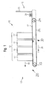
- FIGS. 1 to 5 illustrate preferred embodiments of a vending machine compartment 10.
- the goods compartment 10 is adapted to receive a plurality of cylindrical commodity products 11.
- the in the FIG. 1 formed as cans or bottles cylindrical commodity products 11 are preferably arranged in a designated goods receiving area 12 of the goods compartment 10 and are here preferably upright on a bottom portion 17 of the goods compartment 10.
- This so-called goods receiving area 12 is laterally typically on dedicated wall sections 14, 15, such as For example, sidewalls, grids, webs or the like limited to prevent the goods products 11 can fall laterally out of the goods compartment 10.
- Down the goods receiving area 12 is preferably limited by the bottom portion 17.
- a front side 13 of the goods compartment 10 designates an end face of the goods compartment 10, which in its intended use points to a front door of a vending machine with such a compartment 10.
- the goods compartment 10 To remove a foremost commodity product 11 'from the goods compartment 10, this has an output area 20 on the front side 13 of the goods compartment 10. Now to the foremost commodity product 11 'on the output area 20, the means to be able to remove in the direction 19, the goods compartment 10 has a transport device 30 and an output device 31.
- the goods compartment 10 has according to the embodiment according to FIG. 1 as transport means 30 preferably a bottom side provided on the goods compartment 10, circulating conveyor belt 32. Furthermore, a rotatable roller or roller 33, 34 are provided at the front and at the back, respectively, over which the conveyor belt 32 is tensioned. The upper horizontal region of the conveyor belt 32 forms the bottom portion 17 of the goods compartment 10.
- the conveyor belt 32 is driven here via at least one of these rollers 33, 34, preferably via the front-side roller 33.
- These two rollers 33, 34 are designed to allow a movement of the conveyor belt 32 and thus the cylindrical commodity products 11 thereon with a first transport speed v1 towards the discharge area 20 and thus in the z-direction 21, ie in the direction 19.
- the z-direction 21 corresponds to an output direction or transport direction of the cylindrical commodity products 11.
- the conveyor belt 32 is made of plastic, for example of a plastic with a relatively high Haftreibwiderstand. If the conveyor belt 32 is moved, then the respective cylinder-shaped commodity products 11 standing on the conveyor belt 32 are moved by static friction to the front-side discharge area 20.
- the rollers 33, 34 can be driven for example by specially provided electric motors. It is also particularly advantageous if the transport device 30 via an external drive, that is, an outside of the goods compartment 10 provided drive, which is therefore not part of the goods compartment 10, is driven.
- This drive can preferably be provided via a specially provided removal device.
- This removal device couples for the removal of a commodity, for example, to a specially provided Antriebsankoppel issued the goods compartment 10 and drives, for example via corresponding gears and belts the drive roller 33 at.
- the removal device detects this removal of the cylindrical commodity product 11 ', for example, by a provided at the bottom of the removal tray pressure or weight sensor and then closes, for example, only after a time required for the Nachschieben the further commodity products 11 to the front page 13 time, the removal process. As a result, the transport device 30 is stopped. The removal device then moves to a goods delivery shaft of the vending machine, from which the product just taken out of the goods bay can be removed from the buyer.
- the advantage of this embodiment is that the goods compartment 10 does not have to have its own drive device in this case, which is advantageous in particular for cost reasons.
- a goods compartment 10 also preferably has at the lateral areas of a goods compartment 10 or in the lower Area guide elements, such as guide rails or insertion aids on, by means of which a goods compartment 10 can be pushed into corresponding slide rails or guide aids in the space provided slot of the vending machine into it.
- a goods compartment 10 preferably also has a corresponding latching device 24, by means of which the goods compartment 10 can be latched to corresponding latching points on the housing of the vending machine or in an insertion slot of the vending machine and thus fixed there.
- the goods compartment 10 also has a rear wall 23 on its rear side 16.
- the individual goods compartments 10 within a vending machine are flexible with regard to their size, depending on which cylindrical commodity products 11 are to be sold with them.
- goods compartments 10 can be specifically adapted to the goods to be sold, in particular with regard to their lateral expansions.
- these goods compartments 10 are also removable by pulling out of the interior of the vending machine.
- FIG. 2 shows a side view of another preferred embodiment of a merchandise compartment 10 for a vending machine.
- the transport device 30 of the goods compartment 10 has a slider 38 movable in the z-direction 21.
- This Slider 38 may be optional or alternative to the conveyor belt 32 and the rollers 33, 34 may be provided.
- the slider 38 is mounted on a bottom part 37 of a housing of the goods compartment 10, for example a continuous sheet 37, movable in the z direction.
- a cylindrical product 11 facing surface of the bottom portion 37 forms the bottom portion 17 of the goods compartment 10.
- the slider 38 thus nestles against the last, located in the goods compartment 10 cylindrical product 11 'and pushes it in the Z direction 21 and thus in the direction of the dispensing area 20.
- the transport device 30 may have transport rollers and / or transport rollers.
- FIG. 3 illustrates a front view of the goods compartment 10 according to the FIGS. 1 or 2 .
- a front panel 42 is provided, which is arranged, for example, immediately in front of the drive roller 33 of the conveyor belt 32 - for example, to protect them.
- the goods receiving area 12 laterally delimiting wall sections 14, 15 are provided on both sides.
- the output device 31 of the goods compartment 10 is preferably mounted.
- the goods issue device 31 is arranged directly in the issue area 20.
- the dispensing device 31 in any way, for example by means of corresponding mounting elements, in the goods issue area 20 be mounted.
- the dispenser 31 protrudes from the wall sections 14, 15 into the goods receiving area 12.
- the output device 31 has two plate-shaped elements 43, 44.
- the plate-shaped elements 43, 44 are preferably each connected to one of the wall sections 14, 15.
- Each plate-shaped element preferably has a support portion 45 and a contact portion 46.
- the plate-shaped elements 43, 44 furthermore preferably each have a fastening section 47 mounted on the respective wall section 14, 15.
- the particular finger-shaped support portion 45, the contact portion 46 and the mounting portion 47 may be integrally formed.
- the support section 45 is preferably arranged slightly in front of the contact section 46 with respect to the z-direction 21. In particular, the support section 45 preferably projects further into the goods receiving area 12 than the contact section 46.
- the attachment section 47 is preferably angled relative to the contact section 46 at an angle ⁇ .
- the attachment portion is in particular also angled relative to the attachment portion 47 by an angle ⁇ . The angles ⁇ , ⁇ can be made the same size.
- the contact section 46 is preferably pivotably connected to the attachment section 47 via a, in particular first, hinge section 48.
- the hinge portion 48 may, as in FIG. 4 illustrated, be designed as a hinge 48.
- the dispensing device 31 preferably has at least one, in particular a first, spring section 49.
- the spring portion 49 may, as in FIG. 4 illustrated, be designed as a spring element 49, which pivots the contact portions 46 respectively via the hinge 48 laterally into the goods receiving area 12 and in an in FIG. 4 illustrated initial position spends.
- the support portion 45 is preferably analogous to the contact portion 46 via a, insbesondre second, hinge portion 39 connected to the mounting portion 47 and provided with a, in particular second, spring portion 41.
- the hinge portions 39, 48 may be identical, wherein in this embodiment, the angles ⁇ , ⁇ are preferably different.
- the plate-shaped elements 43, 44 may be elastically deformable at least in sections, wherein the joint sections 39, 48 are not formed as hinges but as elastically deformable regions of the plate-shaped elements 43, 44.
- the spring portions 41, 49 may also be formed as integral components of the plate-shaped elements 43, 44, wherein the plate-shaped elements 43, 44 are at least partially formed with an elastic, in particular a resilient material.
- the support portion 45 and the contact portion 46 form the spring portion 41 and 49, respectively.
- the plate-shaped elements 43, 44 with an elastically deformable plastic material or with formed an elastically deformable metal material.
- the plate-shaped elements 43, 44 are formed with a transparent plastic material.
- the plate-shaped elements 43, 44 or the contact sections 46 and the support sections 45 project obliquely into the goods receiving area 12 in the direction of the discharge area 20.
- the plate-shaped elements 43, 44 can touch or touch approximately in the middle.
- a gear 40 is fixed in the lower region of the goods compartment 10 at the bottom thereof.
- the gear 40 is slightly from the goods compartment 10 from. If a corresponding, suitable for this gear 40 gear, for example via an external drive, brought into engagement with this gear 40, then the gear 40 undergoes a rotational movement. This rotational movement then forms the drive of the goods compartment 10, with which the transport device 30 in the form of the conveyor belt 32 and / or the slider 38 can be driven. This is done by appropriate deflection devices, such as gears and belts, in a conventional manner.
- the goods compartment 10 thus requires no independent drive.
- FIG. 6A shows a standing on the bottom portion 17 cylindrical commodity product 11 '.
- the cylindrical commodity product 11 ' is transported by means of the transport device 30, for example by means of the conveyor belt 32 and / or the slider 38, with the first transport speed v1 in the direction of the discharge area 20, ie in the direction of the output device 31.
- the cylindrical commodity product 11 ' touches the support portions 45 of the plate-shaped elements 43, 44 preferably not yet.
- the contact portions 46 of the plate-shaped elements 43, 44 through the cylindrical commodity product 11' in the direction of the respective wall sections 14, 15 moves toward them, as by means of Arrows 93 illustrates.
- the contact portions 46 pivot about the hinge portions 48 relative to the mounting portions 47.
- the spring portions 48 are biased toward the cylindrical commodity product 11 'down and exerts on this a spring force.
- the dispenser 31 is thus spring-biased by the requested cylindrical product 11 'itself.
- the largest spring force of the contact portions 46 is achieved when a circumference u of the cylindrical commodity product 11 'according to the contact sections FIG. 6B as far as possible in the direction of the wall sections 14, 15 has moved.
- the contact sections are preferably located only at the outermost peripheral points 94, 95 of the circumference u of the cylindrical product 11 '.
- the outermost circumferential points 94, 95 are the points of the circumference u closest to the wall portions in a transverse direction 97 of the goods compartment 10.
- the maximum achievable spring force corresponds to a predetermined output force A of the merchandise dispensing device 31. This predetermined dispensing force A depends, for example, on the geometry and the material of the plate-shaped elements 43, 44, on the spring properties of the spring sections 49 and on the circumference u of the cylindrical product 11 '.
- contact portions 46 contact FIG. 6C the circumference u no longer at the outermost circumferential points 94, 95 but the contact portions 46 slide on the circumference u of the cylindrical product 11 ', which is still in the direction of the output area 20 moves, off. That is, the spring-biased output device 31 is triggered by the requested cylindrical commodity product 11 '.
- the spring bias of the output device 31 causes an acceleration of the cylindrical commodity product 11 'to a second, also acting in the direction of the output area 20, transport speed v2. Since the contact portions 46 preferably only contact the lower region of the cylindrical goods product 11 ', in particular this lower region is accelerated.
- the support sections 45 touch the circumference u of the cylindrical product 11 '.
- the finger-shaped support portions 45 only touch an upper portion of the cylindrical commodity product 11 '.
- the first transport speed v1 of the transport device 30 is preferably less than the second v2 of the output device 31.
- the transport speed v2 is greater by at least 50% and preferably twice as large as the transport speed v1.
- the output by means of the transport speed v2 in the example shown depends on whether the springs 43, 44 have exceeded the center of the bottle.
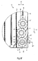
- Fig. 6F shows a further embodiment of a goods compartment, in which the goods compartment according to the invention comprises a device for retaining the rear goods products 11, 11 '' (that is, the goods currently not issued).
- These means 49 'for restraint are here as further springs 49''be formed, wherein the retaining springs 49''exert a lower spring force on the commodity product 11 than the output of the commodity product 11' provided spring portion 46. This is very effective Way realized a separation function.
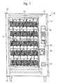
- FIG. 7 shows a frontal plan view of a vending machine 50 with a plurality of goods compartments 10th
- reference numeral 50 generally indicates a vending machine for dispensing bottles and cans of various shapes, sizes, shapes, and liquid capacities.
- the vending machine 50 generally comprises an outer housing 51 or a cabinet and a front door 53 hinged typically to this housing 51 via hinges 52.
- the front door 53 and the housing 51 together form an interior space 54 for storing the cylindrical commodity products 11 to be sold. and to accommodate refrigeration functions of the vending machine 50 and other vending machine functions.
- the front door 53 comprises a transparent glass or clear plastic disk 55, which, when the front door 53 is closed, for a clear view into the interior 54 of the vending machine 50 and thus to the cylindrical commodity products 11 accommodated therein of the vending machine 50 are kept sorted in goods compartments provides.
- a suitable control panel 56 is provided, which comprises product selection input devices and money and credit processing devices, which are well known as well as a coin return device 57.
- a lock unit 58 is provided which allows the front door 53 to be safely opened and closed for maintenance, filling of the vending machine and the like.
- the vending machine 50 also includes a goods issue opening or bin 59 from which a sold cylindrical commodity product 11 can be removed by a buyer.
- the vending machine 50 has a plurality of arrayions in the interior 54 arranged goods compartments 10.
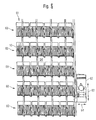
- the FIG. 8 shows the arrangement of these goods compartments 10 in the interior 54 of the vending machine 50th
- the individual goods compartments 10 are arranged here in five different product lines 60 and eight different product compartments 61 side by side or one above the other.
- the individual goods compartments 10 each have the same size here, although this is not absolutely necessary. As has already been described in detail above, it is also advantageous if these goods compartments 10 are variably adjustable in their width, number and / or their height.
- a dedicated removal device 62 For the removal of the cylindrical goods 11, which are in FIG. 8 are not shown, from the various goods compartments 10 is a dedicated removal device 62 is provided.
- This removal device 62 can be moved variably in the y-direction 63 and x-direction 64 and can thus be moved to any front side of a goods compartment 10. This is done via a not shown here, in each case in the x / y direction variable movable transport device to which the removal device 62 is attached.
- This transport device may, for example, contain guide rails on which the removal device 62 can be moved in y-direction 63 and x-direction 64.
- FIG. 9 shows a side view of the interior 54 of the vending machine 50 from FIG. 8 ,
- the individual goods compartments 10 not completely horizontally, that is horizontal, aligned. Rather, the goods compartments 10 are slightly lowered towards the front door side. Alternatively, it would also be conceivable that the goods compartments 10 are aligned completely horizontally
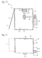
- FIGS. 10 and 11 show an embodiment of a removal device 80 for a vending machine 50 in two different views, in which FIG. 10 a frontal view from the front and FIG. 11 a top view of the removal device 80 shows.
- the removal device 80 essentially comprises a cuboid container, with four side walls and a bottom.
- the removal device 80 is designed to remove a single cylindrical product 11 and is designed to be open at the top.
- a removal compartment in the interior of the housing 81 is defined by the cuboid housing 81 of the removal device 80, which serves to receive a cylindrical commodity product 11.
- a gear designated by reference numeral 83 is fastened via a fastening device 84.
- a drive 85 in particular an electric motor 85, is provided which is fastened to a right side wall 86 of the housing 81.
- the gear 83 is driven by the electric motor 85, wherein the gear belt 87 in corresponding gears, which are coupled via shafts with the gear 83 and the electric motor 85 engages.
- the gear 83 engages in a corresponding gear 40 (see FIG. 3 ) of the sampling compartment 10 and drives this.
- the transport device 30 can be driven via the electric motor 85 of the removal device 80 and by means of the gear belt 87, the gear 83 and the single-sided gear 40, as already described with reference to FIG Figures 1-6 has been shown and described.
- the removal device 80 If the removal device 80 is moved to an output compartment of the vending machine, then the goods product 11 located in the removal compartment 90 can enter the goods issue compartment.
- the commodity is brought in this transport in the removal device in an inclined position. This has the advantage that the bottle is visible by the inclination to the right in the removal opening of the goods output tray .. The goods product can then be removed by a customer directly from the goods output tray.
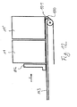
- FIG. 12 shows in cross section a schematic side view of another embodiment of a product compartment according to the invention for a vending machine.
- the commodity products 11, 11 ' are pulled over a pulley 100 via one or more drawstrings 101 or cords attached to a slider 102.
- a traction device is realized.
- This embodiment has the advantage that the goods products 11, 11 'on this type of draw gear or one or more profile struts 103 of the goods compartment direct can stand, which means a better stability of the commodity products 11, 11 '.
- the present invention has been described with reference to a beverage vending machine for dispensing bottles and beverage cans, it is not limited thereto, but can be extended with appropriate modification to the output of any commodity products, for example, cuboidal or arbitrary forms (regular or freeform surfaces) of packaging Beverages and other liquids and commodities, cigarette packs, packaged confectionery products, sandwiches, miscellaneous items such as cameras, spectacles and the like.
- any commodity products for example, cuboidal or arbitrary forms (regular or freeform surfaces) of packaging Beverages and other liquids and commodities, cigarette packs, packaged confectionery products, sandwiches, miscellaneous items such as cameras, spectacles and the like.
Description
Die Erfindung betrifft ein Warenfach für oder in einem Verkaufsautomaten. Die Erfindung betrifft ferner eine Entnahmeeinrichtung, einen solchen Verkaufsautomaten sowie ein Verfahren zum Betreiben des Verkaufsautomaten. Verkaufsautomaten, die in der einschlägigen Literatur häufig auch als Selbstverkäufer bezeichnet werden, können in einer Vielzahl unterschiedlicher Anwendungen ausgebildet sein, so zum Beispiel als Getränkeautomaten, Süßwarenautomaten und dergleichen. Obgleich prinzipiell auf beliebige Verkaufsautomaten anwendbar, wird die vorliegende Erfindung sowie die ihr zugrunde liegende Problematik nachfolgend in Bezug auf Verkaufsautomaten zur Ausgabe von zylinderförmigen Warenprodukten, insbesondere Flaschen, erläutert.The invention relates to a goods compartment for or in a vending machine. The invention further relates to a removal device, such a vending machine and a method for operating the vending machine. Vending machines, which are often referred to in the relevant literature as a self-seller, can be formed in a variety of different applications, such as vending machines, confectionery machines and the like. Although applicable in principle to any vending machine, the present invention and the problem underlying it will be explained below with reference to vending machines for dispensing cylindrical products, in particular bottles.
Verkaufsautomaten weisen im Innenraum Warenaufnahmeeinrichtungen zur Aufnahme der Waren auf. Diese Warenaufnahmeeinrichtungen sind je nach dem, wie die einzelnen Waren innerhalb des Verkaufsautomaten gelagert werden, unterschiedlich ausgestaltet. Während früher die verschiedenen Waren meist schachtweise, übereinander im Innenraum angeordnet und von außen aufgrund einer meist undurchsichtigen Fronttür nicht sichtbar waren, sollen die Waren bei modernen Verkaufsautomaten von außen gut sichtbar sein. Moderne Verkaufsautomaten weisen großflächig mit Glas versehene Fronttüren auf, über die einem potenziellen Käufer das Warenprodukt präsentiert werden soll.Vending machines have in the interior goods receiving devices for receiving the goods. These goods receiving devices are designed differently depending on how the individual goods are stored within the vending machine. Whereas in the past the various goods were usually arranged in shafts, one above the other in the interior and were not visible from the outside due to a mostly opaque front door, the goods should be readily visible from the outside in modern vending machines. Modern vending machines have glass doors on a large area over the one potential buyer the product should be presented.
Bei solchen modernen Verkaufsautomaten sind die Waren meist in zur Frontscheibe ausgerichteten Warenfächern bevorratet, wobei die Warenfächer typischerweise zueinander nebeneinander und/oder übereinander angeordnet sind. Die in den Warenfächern stehenden oder hängenden Waren sind somit über die transparente Frontscheibe für einen potenziellen Käufer sichtbar, was sich aus verkaufstechnischen Gründen als vorteilhaft erwiesen hat. So kann der vermeintliche Käufer direkt, also ohne Sichthindernisse, erkennen, welches Produkt er tatsächlich kauft.In such modern vending machines, the goods are usually stored in goods oriented to the windshield goods compartments, the goods compartments are typically arranged side by side and / or one above the other. The goods standing or hanging in the goods compartments are thus visible on the transparent front screen for a potential buyer, which has proven advantageous for technical reasons. Thus, the alleged buyer can directly, so without obstructions, recognize which product he actually buys.
Für eine Entnahme der in dem jeweiligen Warenfach hintereinander angeordneten Waren werden diese in Richtung eines Ausgabebereiches transportiert, beispielsweise über einen Schieber, eine Förderspirale oder ein Transportband. Das vorderste Warenprodukt fällt dann im Ausgabebereich des Warenfachs in ein Entnahmefach einer eigens dafür vorgesehenen Entnahmeeinrichtung. Anschließend wird die Bewegung des Schiebers bzw. des Transportbandes gestoppt und das Warenfach frontseitig wieder verriegelt.For a removal of the goods in the respective compartment consecutively arranged goods they are transported in the direction of a discharge area, for example via a slide, a conveyor spiral or a conveyor belt. The foremost commodity product then falls in the output area of the goods compartment into a removal compartment of a specially provided removal device. Subsequently, the movement of the slider or the conveyor belt is stopped and locks the goods compartment front side again.
Hierfür weist ein Warenfach eine Antriebseinrichtung auf, beispielsweise einen sensorgesteuerten Schrittmotor. Mittels des Schrittmotors lassen sich das Transportband bzw. der Schieber in eine Transportrichtung bewegen, wobei hierfür typischerweise Zahnräder, Umlenkeinrichtungen, Riemen und dergleichen zum Einsatz kommen können. Bei bekannten Lösungen musste für jedes Warenfach ein eigener Antrieb bereitgestellt werden, was konstruktionstechnisch aufwändig und somit kostenintensiv ist. Zudem ist dies aufgrund der Vielzahl der verwendeten Antriebe auch vergleichsweise fehleranfällig. Fällt einer dieser Antriebe aus, dann ist gewissermaßen die Funktionsweise des gesamten Verkaufsautomaten nicht mehr gewährleistet, da eben aus diesem Warenfach keine Waren mehr entnommen werden können.For this purpose, a goods compartment has a drive device, for example a sensor-controlled stepper motor. By means of the stepping motor, the conveyor belt or the slider can be moved in a transport direction, wherein for this purpose typically gears, deflection devices, belts and the like can be used. In known solutions had to for every department be provided a separate drive, which is technically complex and therefore expensive. In addition, this is due to the large number of drives used also relatively error-prone. If one of these drives fails, then to a certain extent the functioning of the entire vending machine is no longer guaranteed, since goods can no longer be removed from this merchandise compartment.
Während bei bisherigen Verkaufsautomaten eine aus einem solchen Verkaufsautomaten entnommene Ware in ein für alle Warenfächer vorgesehenes, allgemeines Warenausgabefach herunter gefallen ist und von dort entnommen werden konnte, wird dies bei modernen Verkaufsautomaten vermieden. Insbesondere im Falle der oberen Warenfächer fällt eine Ware vergleichsweise sehr tief in das typischerweise bodennah angeordnete Warenausgabefach. Mit dem Herausfallen der Ware aus großer Höhe geht bisweilen eine Beschädigung dieser Ware einher, insbesondere bei Warenprodukten mit einem dünnen, wenig stabilen oder zerbrechlichen Gehäuse oder mit einer flexiblen Verpackung.While in previous vending machines a product taken from such a vending machine has fallen down in a provided for all goods compartments, general goods output tray and could be removed from there, this is avoided in modern vending machines. In particular, in the case of the upper goods compartments, a commodity falls comparatively very deep into the typically arranged near the bottom of the goods output tray. With the falling out of the goods from a great height is sometimes accompanied damage to this product, especially in goods products with a thin, less stable or fragile housing or with a flexible packaging.
Um dies zu vermeiden verfügen moderne Verkaufsautomaten über eine eigens für die Entnahme eines angeforderten Warenproduktes vorgesehene Entnahmeeinrichtung, die entlang der Frontseite der verschiedenen Warenfächer in x/y-Richtung frei verfahrbar ist und somit im Falle einer Warenanforderung ein jeweiliges Warenfach, welches die angeforderte Ware enthält, gezielt anfahren kann. Die angeforderte Ware wird nun von dieser Entnahmeeinrichtung direkt aufgenommen, wobei die angeforderte Ware nur noch eine geringe Höhe in das Fach der Entnahmeeinrichtung fällt und nicht mehr gewissermaßen über die gesamte Höhe des Verkaufsautomaten. Diese Entnahmeeinrichtung befördert die entnommene Ware nach Abschluss des Entnahmevorgangs zu einem eigens dafür vorgesehenen Warenausgabefach des Verkaufsautomaten, welches typischerweise in Hüfthöhe angeordnet ist, so dass der Verkäufer die angeforderte Ware bequem, ohne sich bücken zu müssen, entnehmen kann.In order to avoid this, modern vending machines have a removal device provided specifically for the removal of a requested goods product, which is freely movable along the front side of the various goods compartments in the x / y direction and thus, in the case of a goods request, a respective goods compartment containing the requested goods , can approach specifically. The requested product is now taken directly from this removal device, the requested goods only a small amount falls into the compartment of the removal device and not more or less over the entire Height of the vending machine. This removal device conveys the removed goods after completion of the removal process to a specially provided goods output tray of the vending machine, which is typically located at waist height, so that the seller can conveniently remove the requested goods without having to bend down.
Die
Problematisch bei dieser Form der Entnahme ist allerdings der direkte Entnahmevorgang, bei dem eine im Warenfach befindliche Ware, wenn sie über das Transportband oder den Schieber in Richtung Entnahmevorrichtung befördert wird, an der frontseitigen Kante des Warenfaches quasi mit ihrem oberen Bereich nach vorne kippt, während der Bodenbereich dieser Ware zunächst noch auf dem Boden des Warenfaches stehen bleibt. Dieser Entnahmevorgang führt bei herkömmlichen Verkaufsautomaten mit in x/y-Richtung verfahrbaren Entnahmeeinrichtungen bisweilen zu Störfällen, insbesondere wenn sperrige, breite oder große Waren entnommen werden sollen, bei denen somit die Gefahr besteht, dass sie beim Herausfallen aus dem Warenfach nicht in das dafür vorgesehene Entnahmefach der Entnahmevorrichtung fällt. Dies führt dann meist zu einem Funktionsausfall dieser Entnahmeeinrichtung und somit zu einem Funktionsausfall des gesamten Verkaufsautomaten.The problem with this form of removal, however, is the direct removal process in which a product located in the goods compartment, when it is conveyed over the conveyor belt or the slider in the direction of removal device, tilts at the front edge of the goods compartment quasi with its upper portion forward, while The bottom portion of this product initially still stands on the bottom of the goods compartment. This removal process leads in conventional vending machines with movable in x / y direction removal devices sometimes to incidents, especially if bulky, wide or large goods to be removed, which thus there is a risk that they fall out of the goods compartment not in the space provided Removal compartment of the removal device falls. This usually leads to a malfunction of this removal device and thus to a malfunction of the entire vending machine.
Dies ist ein Zustand, den es verständlicherweise zu vermeiden gilt.This is a condition that, understandably, should be avoided.
Vor diesem Hintergrund liegt der vorliegenden Erfindung die Aufgabe zu Grunde, einen einfachen und insbesondere möglichst störungsfreien Entnahmevorgang bei einem Verkaufsautomaten zu gewährleisten.Against this background, the present invention, the object of a simple and in particular To ensure trouble-free removal process at a vending machine.
Erfindungsgemäß wird diese Aufgabe durch ein Warenfach mit den Merkmalen des Patenanspruchs 1 und/oder durch eine Entnahmeeinrichtung mit den Merkmalen des Patentanspruchs 12 und/oder durch einen Verkaufsautomaten mit den Merkmalen des Patentanspruchs 13 und/oder durch ein Verfahren mit den Merkmalen des Patentanspruchs 15 gelöst.This object is achieved by a goods compartment with the features of claim 1 and / or by a removal device with the features of
Demgemäß ist vorgesehen:
- Ein Warenfach in oder für einen Verkaufsautomaten, mit einem Ausgabebereich zum Ausgeben eines angeforderten Warenproduktes, mit einer Transporteinrichtung, welche dazu ausgelegt ist, das auf einem Bodenabschnitt des Warenfachs angeordnete, angeforderte Warenprodukt mit einer ersten Transportgeschwindigkeit in Richtung des Ausgabebereiches zu befördern, und mit einer Ausgabeeinrichtung, welche unmittelbar in dem Ausgabebereich angeordnet ist und welche zumindest einen Federabschnitt aufweist, wobei die Ausgabeeinrichtung einen Kontaktabschnitt aufweist, der dazu ausgelegt ist einen unteren Bereich des Warenproduktes zu kontaktieren, und einen Stützabschnitt aufweist, der dazu ausgelegt ist einen oberen Bereich des Warenproduktes zu kontaktieren, und
wobei die Ausgabeeinrichtung dazu ausgelegt ist, durch das mit der ersten Transportgeschwindigkeit beförderte angeforderte Warenprodukt vorgespannt zu werden und bei Erreichen einer vorbestimmten Ausgabekraft das angeforderte Warenprodukt im unteren Bereich zu beschleunigen und mit einer zweiten Transportgeschwindigkeit aus dem Ausgabebereich zu befördern. - Eine Entnahmeeinrichtung zur Entnahme eines Warenproduktes aus einem derartigen Warenfach, mit einem zumindest nach oben hin offenes Gehäuse, durch das ein Entnahmefach definiert ist, mit einem Antrieb, mit einer von dem Antrieb angetriebenen Kopplungseinrichtung, die dazu ausgelegt ist, bei einer Entnahme eines Warenproduktes aus einem Warenfach eine Antriebsankoppeleinrichtung des Warenfaches anzutreiben.
- Ein Verkaufsautomat, mit einem Gehäuse, das eine verschließbare Tür zum Befüllen des Verkaufsautomaten aufweist, mit einem Innenraum, mit einer Vielzahl von derartigen Warenfächern, die in dem Innenraum nebeneinander und/oder übereinander angeordnet sind.
- Ein Verfahren zum Betreiben eines derartigen Verkaufsautomaten, bei dem die Warenprodukte in einem Warenfach hintereinander angeordnet sind und bei dem auf eine Warenausgabeanforderung hin ein angefordertes Warenprodukt mit zwei unterschiedlichen Transportgeschwindigkeiten in Richtung eines Ausgabebereichs des Warenfaches transportiert wird.
- A goods compartment in or for a vending machine, having a dispensing area for dispensing a requested goods product, having a transport device which is designed to convey the requested goods product arranged on a bottom section of the goods compartment at a first transport speed in the direction of the dispensing area, and having a dispenser A dispenser disposed directly in the dispensing area and having at least one spring portion, the dispenser having a contact portion adapted to contact a lower portion of the merchandise and having a support portion adapted to an upper portion of the merchandise contact, and
wherein the output device is adapted to be biased by the requested commodity product conveyed at the first transport speed, and to accelerate the requested commodity product in the lower region upon reaching a predetermined output force and to convey it from the output region at a second transport speed. - A removal device for removing a commodity product from such a goods compartment, with an at least upwardly open housing, through the one Removal compartment is defined with a drive, with a driven by the drive coupling device which is adapted to drive at a removal of a commodity from a goods compartment a Antriebsankoppeleinrichtung the goods compartment.
- A vending machine, comprising a housing having a closable door for filling the vending machine, with an interior, with a plurality of such goods compartments, which are arranged in the interior next to each other and / or one above the other.
- A method for operating such a vending machine, in which the goods products are arranged in a goods compartment one behind the other and in which a goods issue request, a requested goods product with two different transport speeds is transported in the direction of an output area of the goods compartment.
Die der vorliegenden Erfindung zu Grunde liegende Idee besteht darin, bei einem Warenfach mit in einer Reihe hintereinander angeordneten Waren eine Transporteinrichtung und eine Ausgabeeinrichtung bereitzustellen, die zwei unterschiedliche Transportgeschwindigkeiten zur Verfügung stellen. Im Falle einer Entnahme werden die einzelnen Warenprodukte in die Richtung des Ausgabebereichs dieses Warenfaches geschoben oder transportiert. Der Transport erfolgt beispielsweise über ein Transportband, einen Schieber oder Transportrollen oder -walzen. Ein zylinderförmiges Warenprodukt wird hier durch eine erste Transportgeschwindigkeit in die Richtung des Ausgabebereichs des Warenfaches transportiert. Im Ausgabebereich des Warenfaches ist die Ausgabeeinrichtung vorgesehen, die eine zweite Transportgeschwindigkeit zur Verfügung stellt. Die Ausgabeeinrichtung wird dabei durch das zylinderförmige Warenprodukt selbst vorgespannt und ausgelöst. Hierbei wird das Warenprodukt auf die zweite Transportgeschwindigkeit beschleunigt. In dem Ausgabebereich soll das angeforderte und auszugebende Warenprodukt an eine eigens dafür vorgesehene Entnahmeeinrichtung, die in bekannter Weise beispielsweise in x/y-Richtung verfahrbar ist, übergeben werden.The idea underlying the present invention is to provide a transport device and an output device in a goods compartment with goods arranged in a row behind one another, which provide two different transport speeds. In the case of removal, the individual goods products are pushed or transported in the direction of the output area of this product compartment. The transport takes place for example via a conveyor belt, a slide or transport rollers or rollers. A cylindrical commodity product is transported here by a first transport speed in the direction of the output area of the goods compartment. In the output area the goods compartment, the output device is provided, which provides a second transport speed. The output device is biased and triggered by the cylindrical product itself. Here, the commodity product is accelerated to the second transport speed. In the output area, the requested and to be dispensed commodity product to a specially provided removal device, which is movable in a known manner, for example in the x / y direction to be passed.
Wesentlich ist, dass die zweite Transportgeschwindigkeit der Ausgabeeinrichtung zumindest größer ist als die erste Transportgeschwindigkeit der Transporteinrichtung. Wesentlich ist ferner, dass die Transportrichtungen der Transporteinrichtung und der Ausgabeeinrichtung gleich sind. Eine zunächst mittels der ersten Transportgeschwindigkeit über die Transporteinrichtung in den Ausgabebereich transportierte Ware wird frontseitig von der im Ausgabebereich angeordneten Ausgabeeinrichtung übernommen. Da die Ausgabeeinrichtung das Warenprodukt auf eine höhere Transportgeschwindigkeit beschleunigt, wird somit der Boden der Ware in die Transportrichtung beschleunigt. Durch Trägheitskräfte wird dadurch der Boden der zu entnehmenden Ware gewissermaßen weggezogen, wodurch verhindert wird, dass der obere Bereich der zu entnehmenden Ware nach vorne, also in Richtung der frontseitigen Entnahmeeinrichtung kippt. Vielmehr wird durch das Bereitstellen zweier unterschiedlicher Transportgeschwindigkeiten sowie deren geeignete Positionierungen innerhalb des Warenfaches sichergestellt, dass eine entnommene Ware immer zunächst mit dem Boden in ein eigens dafür vorgesehenes Entnahmefach innerhalb der Entnahmevorrichtung gleiten kann. Ein Versperren des Entnahmefaches durch ein unerwünschtes Herauskippen der Ware aus dem Warenfach wird dadurch verhindert.It is essential that the second transport speed of the output device is at least greater than the first transport speed of the transport device. It is also essential that the transport directions of the transport device and the output device are the same. A product initially transported by means of the first transport speed over the transport device into the delivery area is taken over at the front by the output device arranged in the exit area. Since the output device accelerates the commodity product to a higher transport speed, thus the bottom of the product is accelerated in the transport direction. As a result of inertial forces, the bottom of the goods to be removed is effectively pulled away, as a result of which the upper region of the goods to be removed is prevented from tipping forward, that is to say in the direction of the front removal device. Rather, it is ensured by providing two different transport speeds and their suitable positioning within the goods compartment that a removed goods always first with the ground in a specially designated removal compartment within the Removal device can slide. An obstruction of the removal compartment by an undesirable tipping out of the goods from the goods compartment is prevented.
Vorzugsweise (jedoch nicht notwendigerweise) sind die Warenprodukte als zylinderförmige Warenprodukte ausgebildet, beispielsweise als Flaschen, Dosen oder dergleichen. In diesem Fall ist die vorbestimmte Kraft dann erreicht, wenn der Federabschnitt an dem größten Umfang des zylinderförmigen Warenproduktes anliegt. Es können aber auch quaderförmig ausgebildete Warenprodukte, wie etwa Warenprodukte mit Tetrapak-Verpackung oder Vitel-Flaschen, ausgegeben werden, sofern sie an den Kanten einen Radius aufweisen oder abgerundet sind.Preferably (but not necessarily), the commodity products are formed as cylindrical commodity products, such as bottles, cans or the like. In this case, the predetermined force is reached when the spring portion abuts against the largest circumference of the cylindrical commodity product. However, it is also possible to output parallelepiped-shaped goods products, such as commodity products with Tetrapak packaging or Vitel bottles, if they have a radius at the edges or are rounded.
Der besondere Vorteil der erfindungsgemäßen Verkaufsautomaten besteht darin, dass die Entnahmeeinrichtung das Warenprodukt direkt zur Ausgabevorrichtung fährt, wo der Kunde das Warenprodukt entnehmen kann. Es erfolgt damit keine zwischengeschaltete Bewegung, umtransportieren, drehen, handhaben, übergeben und dergleichen.The particular advantage of the vending machines according to the invention is that the removal device drives the goods product directly to the dispenser, where the customer can remove the goods product. There is thus no intermediate movement, umtransportieren, turn, handle, pass and the like.
Vorteilhafte Ausgestaltungen und Weiterbildungen der Erfindung ergeben sich aus den weiteren Unteransprüchen sowie aus der Beschreibung in Zusammenschau mit den Figuren der Zeichnung.Advantageous embodiments and modifications of the invention will become apparent from the other dependent claims and from the description in conjunction with the figures of the drawing.
In einer besonders bevorzugten Ausgestaltung ragt die Ausgabeeinrichtung von einem Wandabschnitt des Warenfachs aus in einen Warenaufnahmebereich des Warenfachs hinein. Hierdurch wird zuverlässig ein Vorspannen der Ausgabeeinrichtung und so ein Erreichen der vorbestimmten Ausgabekraft durch das Warenprodukt erreicht. Dies erhöht die Zuverlässigkeit des Warenfachs.In a particularly preferred embodiment, the dispensing device projects from a wall section of the goods compartment into a goods receiving area of the goods compartment. As a result, biasing of the output device and thus achievement of the predetermined one becomes reliable Output power achieved by the commodity product. This increases the reliability of the goods compartment.
In einer weiteren bevorzugten Ausgestaltung ist die Ausgabeeinrichtung dazu ausgelegt, einen Umfang des angeforderten Warenproduktes bei dem Vorspannen des zumindest einen Federabschnittes zumindest abschnittsweise zu kontaktieren. Diese Ausgestaltung hat den Vorteil, dass hier auf eine eigens vorgesehene Verriegelung im frontseitigen Ausgabebereich des Warenfaches verzichtet werden kann, da die einzelnen Warenprodukte bei einer ausgeschalteten Transporteinrichtung zuverlässig von der Ausgabeeinrichtung in dem Warenfach zurückgehalten werden. Ein Zurückhalten der Warenprodukte durch einen zusätzlichen Riegel, einen Bügel oder eine Klappe ist daher nicht erforderlich.In a further preferred embodiment, the dispensing device is adapted to at least partially contact a scope of the requested goods product during the pretensioning of the at least one spring section. This embodiment has the advantage that it is possible to dispense with a specially provided locking in the front-side dispensing area of the goods compartment, since the individual goods products are reliably retained by the dispensing device in the goods compartment when the transport device is switched off. Retention of the goods by an additional bar, a strap or a flap is therefore not required.
In einer bevorzugten Weiterbildung weist die Ausgabeeinrichtung einen Kontaktabschnitt, der dazu ausgelegt ist einen unteren Bereich des Warenproduktes zu kontaktieren, und einen Stützabschnitt auf, der dazu ausgelegt ist einen oberen Bereich des Warenproduktes zu kontaktieren. Hierdurch wird eine zuverlässige Führung des Warenproduktes gewährleistet, wodurch die Betriebszuverlässigkeit des Warenfaches erhöht wird.In a preferred development, the dispensing device has a contact section, which is designed to contact a lower region of the product, and a support section, which is designed to contact an upper region of the product. As a result, a reliable guidance of the goods product is ensured, whereby the operational reliability of the goods compartment is increased.
In einer weiteren bevorzugten Ausführungsform weist das erfindungsgemäße Warenfach eine Einrichtung zur Rückhaltung der hinteren Warenprodukte (also der gerade nicht ausgegebenen Warenprodukte) auf. Diese Einrichtung zur Rückhaltung kann z.B. durch weitere Federn ausgebildet sein, wobei die rückhaltenden Federn eine geringere Federkraft auf das Produkt ausüben, als der zur Ausgabe des Warenprodukts vorgesehene Federabschnitt. Dadurch wird eine Trennfunktion realisiert.In a further preferred embodiment, the goods compartment according to the invention has a device for retaining the rear goods products (that is to say the goods products that have not yet been issued). This means for restraint may be formed, for example, by further springs, wherein the retaining springs exert a lower spring force on the product, as the output of the product product provided spring section. As a result, a separation function is realized.
In einer bevorzugten Ausführungsform ist die zweite Transportgeschwindigkeit größer als die erste Transportgeschwindigkeit, wobei die zweite Transportgeschwindigkeit insbesondere um mindestens 30%, vorzugsweise um mindestens 50% und noch bevorzugter um mindesten das Doppelte größer ist als die erste Transportgeschwindigkeit. Hierdurch wird zuverlässig der untere, gegenüber dem oberen Bereich des zylinderförmigen Warenproduktes stärker beschleunigte, Bereich des zylinderförmigen Warenproduktes zuerst aus dem Warenausgabebereich ausgegeben, wodurch sich die Betriebszuverlässigkeit des Warenfachs erhöht.In a preferred embodiment, the second transport speed is greater than the first transport speed, the second transport speed being, in particular, at least 30%, preferably at least 50%, and more preferably at least twice the first transport speed. As a result, the lower, compared to the upper portion of the cylindrical product product more accelerated, the range of the cylindrical product product is reliably output from the goods issue area first, thereby increasing the reliability of the goods compartment.
In einer weiteren bevorzugten Ausführungsform weist die Transporteinrichtung einen Schieber auf, der dazu ausgelegt ist, die in dem Warenfach befindlichen Warenprodukte mit der ersten Transportgeschwindigkeit zu dem Ausgabebereich zu schieben. Hierdurch wird durch den formschlüssigen Kontakt des Schiebers mit dem Warenprodukt zuverlässig ein Transport desselben zu dem Ausgabebereich gewährleistet. Die Gefahr eines Verklemmens des Warenproduktes in dem Warenfach wird reduziert.In a further preferred embodiment, the transport device has a slide which is designed to push the goods products located in the goods compartment at the first transport speed to the delivery area. As a result, the transport of the same is reliably ensured by the positive contact of the slider with the product of the product to the dispensing area. The risk of jamming of the product in the goods compartment is reduced.
In einer alternativen, aber ebenso bevorzugten Ausgestaltung weist die Transporteinrichtung ein um zwei drehbare oder feststehende Walzen gespanntes Transportband auf, welches dazu ausgelegt ist, die in dem Warenfach befindlichen Warenprodukte mit der ersten Transportgeschwindigkeit zu dem Ausgabebereich zu transportieren. Hierdurch ist ein besonders einfacher und kostengünstiger Aufbau des Warenfaches gewährleistet.In an alternative, but also preferred embodiment, the transport device has a conveyor belt tensioned about two rotatable or stationary rollers, which is designed to transport the goods products located in the goods compartment at the first transport speed to the delivery area. As a result, a particularly simple and inexpensive construction of the product compartment is guaranteed.
In einer weiteren, ebenfalls bevorzugten Ausgestaltung weist das Warenfach keinen eigenen Antrieb auf. Vorzugsweise ist eine Antriebsankoppeleinrichtung zur Ankopplung zumindest eines externen Antriebs vorgesehen. Zum Antreiben der Transporteinrichtung weist das Warenfach die eigens dafür vorgesehene Antriebsankoppeleinrichtung auf, die mit einem externen Antrieb in Eingriff gebracht werden kann. Über den externen Antrieb und die Antriebsankoppeleinrichtung kann somit die Transporteinrichtung eines Warenfaches angetrieben werden. Der Vorteil besteht bei dieser Ausgestaltung darin, dass das Warenfach nicht mehr über einen eigenen Antrieb verfügen muss, was aus Kostensicht von Vorteil und zudem auch wartungsunempfindlicher ist.In a further, likewise preferred embodiment, the goods compartment does not have its own drive. Preferably, a drive coupling device is provided for coupling at least one external drive. To drive the transport device, the goods compartment on the specially provided Antriebsankoppeleinrichtung, which can be brought into engagement with an external drive. Thus, the transport device of a goods compartment can be driven via the external drive and the drive coupling device. The advantage of this embodiment is that the goods compartment no longer has to have its own drive, which is advantageous from a cost point of view and also less sensitive to maintenance.
Besonders vorteilhaft ist es, wenn hier lediglich ein einziger, zentraler Antrieb vorgesehen wird, der für sämtliche Warenfächer innerhalb eines Verkaufsautomaten verwendet werden kann.It is particularly advantageous if only a single, central drive is provided here, which can be used for all goods compartments within a vending machine.
In einer weiteren Ausführungsform weist die Antriebsankoppeleinrichtung zumindest ein Zahnrad auf. Das Zahnrad ist bevorzugt im Ausgabebereich des Warenfaches, insbesondere unter einem Bodenbereich des Warenfaches, angeordnet. Hierdurch ist ein besonders platzsparender Aufbau des Warenfaches gewährleistet.In a further embodiment, the drive coupling device has at least one toothed wheel. The gear is preferably arranged in the output area of the goods compartment, in particular under a floor area of the goods compartment. As a result, a particularly space-saving construction of the goods compartment is guaranteed.
Eine besondere Ausgestaltung sieht vor, dass die direkte Aufnahme der Reaktionskräfte aus den Zahnrädern der Koppeleinrichtung direkt von dem Zahnrad des Warenfachs über ein geeignetes krallenähnliches Verbindungselement direkt in die Koppeleinrichtung eingeleitet wird.A particular embodiment provides that the direct recording of the reaction forces from the gears of the coupling device directly from the gear of the goods compartment is introduced directly into the coupling device via a suitable claw-like connecting element.
In einer alternativen, aber ebenso bevorzugten Ausgestaltung werden die Warenprodukte über ein oder mehrere Bänder oder Schnüre, die an einem Schieber angebracht sind, gezogen. Dadurch wird eine Zugeinrichtung realisiert. Diese Ausgestaltung hat den Vorteil, dass die Warenprodukte auf den Zugeinrichtungen oder einem oder mehreren Profilstreben des Warenfaches stehen können.In an alternative but equally preferred embodiment, the commodity products are pulled over one or more straps or cords attached to a slider. As a result, a traction device is realized. This embodiment has the advantage that the goods products can stand on the traction devices or one or more profile struts of the goods compartment.
Die Erfindung wird nachfolgend anhand der in den Figuren der Zeichnung angegebenen Ausführungsbeispiele näher erläutert. Dabei zeigen:
- Figur 1
- im Querschnitt eine schematische Seitendarstellung eines bevorzugten Ausführungsbeispiels eines erfindungsgemäßen Warenfaches für einen Verkaufsautomaten;
- Figur 2
- im Querschnitt eine schematische Seitendarstellung eines weiteren bevorzugten Ausführungsbeispiels eines erfindungsgemäßen Warenfaches für einen Verkaufsautomaten;
- Figur 3
- eine Vorderansicht auf ein erfindungsgemäßes Warenfach von der Frontseite;
- Figur 4
- in einer Draufsicht eine schematische Seitendarstellung eines bevorzugten Ausführungsbeispiels eines erfindungsgemäßen Warenfaches für einen Verkaufsautomaten;
- Figur 5
- in einer Draufsicht eine schematische Seitendarstellung eines weiteren bevorzugten Ausführungsbeispiels eines erfindungsgemäßen Warenfaches für einen Verkaufsautomaten;
- Figur 6A - 6F
- schematische Darstellungen zur Erläuterung der erfindungsgemäßen Funktion des Warenfachs gemäß der
Figuren 1 bis 5 ; - Figur 7
- eine frontale Draufsicht auf einen erfindungsgemäßen Verkaufsautomaten mit einer Vielzahl erfindungsgemäßer Warenfächer;
Figur 8- eine frontale Darstellung auf den Innenraum des Verkaufsautomaten entsprechend
Figur 7 im Bereich der Warenfächer; - Figur 9
- eine seitliche Darstellung des Innenraums des Verkaufsautomaten aus
Figur 8 ; Figur 10- eine frontale Draufsicht auf eine erfindungsgemäße Entnahmeeinrichtung für einen Verkaufsautomaten; und
Figur 11- eine Draufsicht von oben auf die erfindungsgemäße Entnahmeeinrichtung aus
Figur 10 , Figur 12- im Querschnitt eine schematische Seitendarstellung eines weiteren Ausführungsbeispiels eines erfindungsgemäßen Warenfaches für einen Verkaufsautomaten.
- FIG. 1
- in cross section a schematic side view of a preferred embodiment of a product compartment according to the invention for a vending machine;
- FIG. 2
- in cross section a schematic side view of another preferred embodiment of a product compartment according to the invention for a vending machine;
- FIG. 3
- a front view of an inventive merchandise compartment from the front side;
- FIG. 4
- in a plan view of a schematic side view of a preferred embodiment of a product compartment according to the invention for a vending machine;
- FIG. 5
- in a plan view of a schematic side view of another preferred embodiment of a product compartment according to the invention for a vending machine;
- FIGS. 6A-6F
- schematic representations for explaining the inventive function of the goods compartment according to the
FIGS. 1 to 5 ; - FIG. 7
- a frontal plan view of a vending machine according to the invention with a variety of invented goods compartments;
- FIG. 8
- a frontal representation corresponding to the interior of the vending machine
FIG. 7 in the field of goods subjects; - FIG. 9
- a side view of the interior of the vending machine
FIG. 8 ; - FIG. 10
- a frontal plan view of a removal device according to the invention for a vending machine; and
- FIG. 11
- a plan view from above of the removal device according to the invention
FIG. 10 . - FIG. 12
- in cross section a schematic side view of another embodiment of a product compartment according to the invention for a vending machine.
In den Figuren der Zeichnung sind gleiche und funktionsgleiche Elemente, Merkmale und Signale, sofern nichts Anderes ausgeführt wurde, mit denselben Bezugszeichen versehen.In the figures of the drawing, the same and functionally identical elements, features and signals, unless otherwise stated, provided with the same reference numerals.
Die
Das Warenfach 10 ist dazu ausgelegt, mehrere zylinderförmige Warenprodukte 11 aufzunehmen. Die in der
Zur Entnahme eines vordersten Warenproduktes 11' aus dem Warenfach 10 weist dieses einen Ausgabebereich 20 an der Frontseite 13 des Warenfaches 10 auf. Um nun das vorderste Warenprodukt 11' über den Ausgabebereich 20, das heißt in Richtung 19, entnehmen zu können, weist das Warenfach 10 eine Transporteinrichtung 30 sowie eine Ausgabeeinrichtung 31 auf.To remove a foremost commodity product 11 'from the
Das Warenfach 10 weist gemäß der Ausführungsform nach
Vorzugsweise ist das Transportband 32 aus Kunststoff, beispielsweise aus einem Kunststoff mit relativ hohem Haftreibwiderstand. Wird das Transportband 32 bewegt, dann werden die jeweiligen, auf dem Transportband 32 stehenden zylinderförmigen Warenprodukte 11 durch Haftreibung zum frontseitigen Ausgabebereich 20 bewegt.Preferably, the
Die Walzen 33, 34 können beispielsweise durch eigens dafür vorgesehene Elektromotoren angetrieben werden. Besonders vorteilhaft ist es ferner, wenn die Transporteinrichtung 30 über einen externen Antrieb, das heißt einen außerhalb des Warenfaches 10 vorgesehenen Antrieb, der also nicht Bestandteil des Warenfaches 10 ist, angetrieben wird. Dieser Antrieb kann vorzugsweise über eine eigens dafür vorgesehene Entnahmevorrichtung bereitgestellt werden. Diese Entnahmevorrichtung koppelt sich für die Entnahme eines Warenproduktes beispielsweise an eine eigens dafür vorgesehene Antriebsankoppeleinrichtung des Warenfaches 10 an und treibt beispielsweise über entsprechende Zahnräder und Riemen die Antriebswalze 33 an.The
Bei dem Entnehmen des zylinderförmigen Warenproduktes 11' aus dem Warenfach 10 fällt dieses in ein eigens dafür vorgesehenes Entnahmefach der Entnahmevorrichtung. Die Entnahmevorrichtung detektiert dieses Entnehmen des zylinderförmigen Warenproduktes 11' beispielsweise durch einen am Boden des Entnahmefaches vorgesehenen Druckoder Gewichtssensor und schließt dann, beispielsweise auch erst nach einer für das Nachschieben der weiteren Warenprodukte 11 zur Frontseite 13 hin erforderlichen Zeitspanne, den Entnahmevorgang ab. Dadurch wird die Transporteinrichtung 30 gestoppt. Die Entnahmevorrichtung fährt dann zu einem Warenausgabeschacht des Verkaufsautomaten, von dem das soeben aus dem Warenschacht herausgenommene Warenprodukt von dem Käufer entnommen werden kann. Der Vorteil dieser Ausgestaltung ist, dass das Warenfach 10 in diesem Falle keine eigene Antriebseinrichtung aufweisen muss, was insbesondere aus Kostengründen von Vorteil ist.When removing the cylindrical product 11 'from the
Ein Warenfach 10 weist ferner vorzugsweise an den seitlichen Bereichen eines Warenfaches 10 oder im unteren Bereich Führungselemente, beispielsweise Führungsschienen oder Einschubhilfen, auf, mittels derer ein Warenfach 10 in entsprechende Einschubschienen oder Führungshilfen in den dafür vorgesehenen Einschubschacht des Verkaufsautomaten hinein geschoben werden kann.A
Ein Warenfach 10 weist vorzugsweise auch eine entsprechende Einrasteinrichtung 24 auf, mittels der das Warenfach 10 an entsprechenden Einraststellen am Gehäuse des Verkaufsautomaten bzw. in einem Einschubschacht des Verkaufsautomaten eingerastet werden kann und somit dort fixiert ist.A
Das Warenfach 10 weist an seiner Rückseite 16 ferner eine Rückwand 23 auf.The
Die einzelnen Warenfächer 10 innerhalb eines Verkaufsautomaten sind flexibel hinsichtlich deren Größe, je nachdem welche zylinderförmigen Warenprodukte 11 mit ihnen verkauft werden sollen. So lassen sich innerhalb des Verkaufsautomaten Warenfächer 10 insbesondere hinsichtlich ihrer lateralen Ausdehnungen gezielt auf die zu verkaufenden Waren anpassen. Zusätzlich sind diese Warenfächer 10 auch durch Herausziehen aus dem Innenraum des Verkaufsautomaten entnehmbar.The individual goods compartments 10 within a vending machine are flexible with regard to their size, depending on which
Die
Im Unterschied zu dem Ausführungsbeispiel gemäß
Die
Insbesondere weist die Ausgabeeinrichtung 31 zwei plattenförmige Elemente 43, 44 auf. Die plattenförmigen Elemente 43, 44 sind vorzugsweise jeweils mit einem der Wandabschnitte 14, 15 verbunden. Jedes plattenförmige Element weist vorzugsweise einen Stützabschnitt 45 und einen Kontaktabschnitt 46 auf. Die plattenförmigen Elemente 43, 44 weisen ferner vorzugsweise jeweils einen an dem jeweiligen Wandabschnitt 14, 15 montierten Befestigungsabschnitt 47 auf. Der insbesondere fingerförmig ausgebildete Stützabschnitt 45, der Kontaktabschnitt 46 und der Befestigungsabschnitt 47 können einteilig ausgebildet sein. Der Stützabschnitt 45 ist dabei bezüglich der z-Richtung 21 vorzugsweise etwas vor dem Kontaktabschnitt 46 angeordnet. Insbesondere ragt der Stützabschnitt 45 vorzugsweise weiter in der Warenaufnahmebereich 12 hinein als der Kontaktabschnitt 46. Der Befestigungsabschnitt 47 ist gegenüber dem Kontaktabschnitt 46 vorzugsweise um einen Winkel α abgewinkelt. Der Befestigungsabschnitt ist insbesondere ebenfalls gegenüber dem Befestigungsabschnitt 47 um einen Winkel β abgewinkelt. Die Winkel α, β können gleich groß ausgebildet sein.In particular, the
Der Kontaktabschnitt 46 ist mit dem Befestigungsabschnitt 47 vorzugsweise über einen, insbesondere ersten, Gelenkabschnitt 48 verschwenkbar verbunden. Der Gelenkabschnitt 48 kann, wie in
In einer alternativen Ausführungsform des Warenfachs 10 gemäß
In der Aufsicht auf das Warenfach 10 gemäß der
Gemäß
Nachfolgend wird die Funktionsweise des Warenfaches 10 und somit das Zusammenspiel der Transportvorrichtung 30 und der Ausgabeeinrichtung 31- anhand der
Die größte Federkraft der Kontaktabschnitte 46 wird erreicht wenn ein Umfang u des zylinderförmige Warenproduktes 11' die Kontaktabschnitte gemäß
Unmittelbar nach dem Erreichen der vorbestimmte Ausgabekraft A, d.h. sobald die vorbestimmte Ausgabekraft A erreicht ist, kontaktieren die Kontaktabschnitte 46 gemäß
Während die Kontaktabschnitte 46 auf dem Umfang u abgleiten wird das zylinderförmige Warenprodukt 11' gemäß
Die erste Transportgeschwindigkeit v1 der Transportvorrichtung 30 ist vorzugsweise geringer als die zweite v2 der Ausgabeeinrichtung 31. Vorzugsweise ist die Transportgeschwindigkeit v2 um mindestens 50% größer und vorzugsweise doppelt so groß wie die Transportgeschwindigkeit v1.The first transport speed v1 of the
Die Ausgabe mittels der Transportgeschwindigkeit v2 hängt im gezeigten Beispiel davon ab, ob die Federn 43, 44 den Mittelpunkt der Flasche überschritten haben.The output by means of the transport speed v2 in the example shown depends on whether the
Die
Ferner ist eine Verriegelungseinheit 58 vorgesehen, die es ermöglicht, dass die Fronttür 53 zu Zwecken der Wartung, des Befüllens des Verkaufsautomaten und dergleichen auf sichere Weise geöffnet und geschlossen werden kann. Der Verkaufsautomat 50 umfasst auch eine Warenausgabe-Öffnung oder ein Ausgabefach 59, aus der ein verkauftes zylinderförmiges Warenprodukt 11 von einem Käufer entnehmbar ist.Further, a
Der Verkaufsautomat 50 weist eine Vielzahl arraymäßig im Innenraum 54 angeordneter Warenfächer 10 auf. Die
Die einzelnen Warenfächer 10 sind hier in fünf verschiedenen Warenfachzeilen 60 und acht verschiedenen Warenfachspalten 61 nebeneinander bzw. übereinander angeordnet. Die einzelnen Warenfächer 10 weisen hier jeweils dieselbe Größe auf, was allerdings nicht zwingend erforderlich ist. Wie bereits oben ausführlich beschrieben wurde, ist es ebenfalls vorteilhaft, wenn diese Warenfächer 10 in ihrer Breite, Anzahl und/oder in ihrer Höhe variabel einstellbar sind.The individual goods compartments 10 are arranged here in five
Für die Entnahme der zylinderförmigen Warenprodukte 11, die in
Die
Die
Die Entnahmeeinrichtung 80 umfasst im Wesentlichen einen quaderförmigen Behälter, mit vier Seitenwänden und einen Boden. Die Entnahmeeinrichtung 80 ist zur Entnahme eines einzelnen zylinderförmigen Warenproduktes 11 ausgelegt und ist zu diesem Zwecke nach oben hin offen ausgebildet. Somit wird durch das quaderförmige Gehäuse 81 der Entnahmeeinrichtung 80 ein Entnahmefach im Inneren des Gehäuses 81 definiert, welches der Aufnahme eines zylinderförmigen Warenproduktes 11 dient.The
An der frontalen Gehäusewand 82 ist ein mit Bezugszeichen 83 bezeichnetes Zahnrad über eine Befestigungsvorrichtung 84 befestigt. Zum Antreiben dieses Zahnrads 83 ist ein Antrieb 85, insbesondere ein Elektromotor 85, vorgesehen, der an einer rechten Seitenwand 86 des Gehäuses 81 befestigt ist. Über einen Zahnradriemen 87 wird das Zahnrad 83 von dem Elektromotor 85 angetrieben, wobei der Zahnradriemen 87 in entsprechende Zahnräder, die über Wellen mit dem Zahnrad 83 und dem Elektromotor 85 gekoppelt sind, eingreift.On the
Wird die Entnahmeeinrichtung 80 zu einem der Warenfächer 10 eines Verkaufsautomaten 50 bewegt, dann greift das Zahnrad 83 in ein entsprechendes Zahnrad 40 (siehe
Wird die Entnahmeeinrichtung 80 zu einem Ausgabefach des Verkaufsautomaten bewegt, dann kann das im Entnahmefach 90 befindliche Warenprodukt 11 in das Warenausgabefach gelangen. Vorzugsweise wird das Warenprodukt bei diesem Transport in der Entnahmeeinrichtung in eine Schräglage gebracht. Das hat den Vorteil, dass die Flasche durch die Neigung nach rechts in der Entnahmeöffnung des Warenausgabefaches sichtbar wird.. Das Warenprodukt kann dann von einem Kunden direkt aus dem Warenausgabefach entnommen werden.If the
Wenngleich die vorliegende Erfindung anhand eines Getränkeautomaten zur Ausgabe von Flaschen und Getränkedosen beschrieben wurde, ist sie nicht darauf beschränkt, sondern lässt sich bei entsprechender Modifikation auf die Ausgabe beliebiger Warenprodukte erweitern, beispielsweise auf quaderförmige oder beliebige Formen (Regel- oder Freiformflächen) von Verpackungen von Getränken und anderen Flüssigkeiten und Warenprodukten , Zigarettenpackungen, verpackte Süßigkeitsprodukte, Sandwichs, sonstige Gegenstände wie Fotoapparate, Brillen und dergleichen.Although the present invention has been described with reference to a beverage vending machine for dispensing bottles and beverage cans, it is not limited thereto, but can be extended with appropriate modification to the output of any commodity products, for example, cuboidal or arbitrary forms (regular or freeform surfaces) of packaging Beverages and other liquids and commodities, cigarette packs, packaged confectionery products, sandwiches, miscellaneous items such as cameras, spectacles and the like.
- 1010
- Warenfachwere trade
- 11, 11', 11''11, 11 ', 11' '
- zylinderförmige Warenproduktecylindrical goods products
- 1212
- WarenaufnahmebereichGoods receiving area
- 1313
- Frontseitefront
- 1414
- Wandabschnittwall section
- 1515
- Wandabschnittwall section
- 1616
- Rückseiteback
- 1717
- Bodenabschnittbottom section
- 1919
- Richtungdirection
- 2020
- Ausgabebereichoutput area
- 2121
- z-Richtungz-direction
- 2323
- Rückwandrear wall
- 2424
- Einrasteinrichtunglatching
- 3030
- Transporteinrichtungtransport means
- 3131
- Ausgabeeinrichtungoutput device
- 3232
- Transportbandconveyor belt
- 3333
- Walzeroller
- 3434
- Walzeroller
- 3737
- Bodenteilthe bottom part
- 3838
- beweglicher Schiebermovable slide
- 3939
- Gelenkabschnitthinge section
- 4040
- Zahnradgear
- 4141
- Federabschnittspring section
- 4242
- Blendecover
- 4343
- plattenförmiges Elementplate-shaped element
- 4444
- plattenförmiges Elementplate-shaped element
- 4545
- Stützabschnittsupport section
- 4646
- KontaktabschnittContact section
- 4747
- Befestigungsabschnittattachment section
- 4848
- Gelenkabschnitthinge section
- 4949
- Federabschnittspring section
- 49'49 '
- Einrichtung zum ZurückhaltenRetention device
- 49''49 ''
- Federnfeathers
- 5050
- Verkaufsautomatvending machine
- 5151
- Gehäusecasing
- 5252
- Gelenkjoint
- 5353
- Fronttürfront door
- 5454
- Innenrauminner space
- 5555
- Scheibedisc
- 5656
- Bedieneinrichtungoperating device
- 5757
- Münzausgabeeinrichtungcoin dispenser
- 5858
- Verriegelungseinrichtunglocking device
- 5959
- Ausgabefachoutput tray
- 6060
- WarenfachzeileWere trade row
- 6161
- WarenfachspalteWere trade gaps
- 6262
- Entnahme-EinrichtungUnloader
- 6363
- y-Richtungy-direction
- 6464
- x-Richtungx-direction
- 8080
- Entnahmeeinrichtungremoval device
- 8181
- Gehäusecasing
- 8282
- frontseitige Gehäusewandfront housing wall
- 8383
- Zahnradgear
- 8484
- Befestigungsvorrichtungfastening device
- 8585
- Elektromotorelectric motor
- 8686
- SeitenwandSide wall
- 8787
- Zahnradriemengear belt
- 9090
- Entnahmefachwithdrawal compartment
- 9191
- schwenkbare Klappeswiveling flap
- 9292
- Gelenkjoint
- 9393
- Pfeilarrow
- 9494
- Umfangspunktperipheral point
- 9595
- Umfangspunktperipheral point
- 9797
- Querrichtungtransversely
- 100100
- Umlenkrolleidler pulley
- 101101
- Zugbandtieback
- 102102
- Schieberpusher
- 103103
- Profilstrebenprofile struts
- AA
- Ausgabekraftoutput power
- uu
- Umfangscope
- v1v1
- erste Transportgeschwindigkeitfirst transport speed
- v2v2
- zweite Transportgeschwindigkeitsecond transport speed
- zz
- Transportrichtung entlang des WarenfachesTransport direction along the goods compartment
Claims (14)
- Product compartment (10) in or for a vending machine (50),
comprising an output region (20) for outputting a requested product (11), in particular a cylindrical product (11),
comprising a transport device (31) which is configured to convey the requested product (11) arranged on a base section (17) of the product compartment (10) at a first transporting speed (v1) towards the output region (20), and
comprising an output device (31) which is arranged directly in the output region (20) and which has at least one spring section (49), wherein the output device (31) has a contact section (46) which is configured to contact a lower region of the product (11), and has a support section (45) which is configured to contact an upper region of the product (11), and
wherein the output device (31) is configured to be pre-stressed by the requested cylindrical product (11) conveyed at the first transporting speed (v1) and, when a predetermined output force (A) is reached, to accelerate the requested product (11) in the lower region and to convey same at a second transporting speed (v2) out of the output region (20). - Product compartment as claimed in claim 1, characterised in that the output device (31) protrudes from a wall section (14, 15) of the product compartment (10) into a product-receiving region (12) of the product compartment (10).
- Product compartment as claimed in claim 1 or 2, characterised in that the output device (31) is configured to contact, at least in sections, a periphery (u) of the requested product (11) when the at least one spring section (49) is being pre-stressed.
- Product compartment as claimed in any one of the preceding claims, characterised in that the second transporting speed (v2) is greater than the first transporting speed (v1), wherein the second transporting speed (v2) is greater than the first transporting speed (v1) in particular by at least 30%, preferably by at least 50% and even more preferably by at least twice.
- Product compartment as claimed in any one of the preceding claims, characterised in that the transport device (30) has a slide (38) which is configured to push the products (11), located in the product compartment (10), to the output region (20) at the first transporting speed (v1).
- Product compartment as claimed in any one of the preceding claims, characterised in that the transporting device (30) has a transport belt (32) which is tensioned around two rotatable rollers (33, 34) and is configured to transport the products, located in the product compartment (10), to the output region (20) at the first transporting speed (v1).
- Product compartment as claimed in any one of the preceding claims, characterised in that the product compartment (10) is formed in a drive-less manner.
- Product compartment as claimed in any one of the preceding claims, characterised in that a drive coupling device for coupling at least one external drive is provided.
- Product compartment as claimed in claim 8, characterised in that the drive coupling device has at least one toothed wheel (40).
- Product compartment as claimed in claim 9, characterised in that the toothed wheel (40) is arranged in the output region (20) of the product compartment (10), in particular below a base region of the product compartment (10).
- Removal device (80) for removing a product (11) from a product compartment (10) as claimed in any one of claims 1 to 10,
comprising a housing (81) which is open at least at the top and by means of which a removal compartment is defined,
comprising a drive (85),
comprising a coupling device which is driven by the drive (85) and is configured to drive a drive coupling device of a product compartment (10) when a product (11) is being removed from the product compartment (10). - Vending machine (50),
comprising a housing (51) which has a closable door (53) for filling the vending machine (50),
comprising an interior space (54),
comprising a plurality of product compartments (10) as claimed in any one of claims 1 to 10, which compartments are arranged next to each other and/or one above the other in the interior space (54). - Vending machine as claimed in claim 12, characterised in that a removal device (80) as claimed in claim 12 is provided.
- Method for operating a vending machine as claimed in claim 12,- wherein the products (11) are arranged one behind the other in a product compartment (10), and- wherein a requested product (11), in response to a product output request, is transported at two different transporting speeds (v1, v2) towards an output region (20) of the product compartment (10).
Applications Claiming Priority (1)
| Application Number | Priority Date | Filing Date | Title |
|---|---|---|---|
| DE102011082378A DE102011082378B4 (en) | 2011-09-08 | 2011-09-08 | Merchandise compartment, vending machine and process |
Publications (2)
| Publication Number | Publication Date |
|---|---|
| EP2568453A1 EP2568453A1 (en) | 2013-03-13 |
| EP2568453B1 true EP2568453B1 (en) | 2016-03-23 |
Family
ID=46511064
Family Applications (1)
| Application Number | Title | Priority Date | Filing Date |
|---|---|---|---|
| EP12179352.5A Active EP2568453B1 (en) | 2011-09-08 | 2012-08-06 | Product compartment, extraction device, vending machine and method |
Country Status (3)
| Country | Link |
|---|---|
| EP (1) | EP2568453B1 (en) |
| DE (2) | DE102011082378B4 (en) |
| ES (1) | ES2569882T3 (en) |
Families Citing this family (2)
| Publication number | Priority date | Publication date | Assignee | Title |
|---|---|---|---|---|
| CN110728790B (en) * | 2018-07-16 | 2021-11-05 | 山东新北洋信息技术股份有限公司 | Automatic vending machine and goods channel goods delivery control method thereof |
| DE102020201679A1 (en) | 2020-02-11 | 2021-08-12 | Sielaff GmbH & Co. KG Automatenbau Herrieden | Goods compartment and method for selectively driving individual conveying devices of a goods compartment |
Family Cites Families (3)
| Publication number | Priority date | Publication date | Assignee | Title |
|---|---|---|---|---|
| DE69807343T2 (en) * | 1998-11-30 | 2003-04-24 | Sanyo Electric Co | Goods storage device for vending machine |
| US20070017928A1 (en) * | 2005-07-20 | 2007-01-25 | Coppola Richard G | Method of retrofitting a vending machine |
| EP1947619B1 (en) * | 2006-10-25 | 2015-03-04 | Sielaff Gmbh & Co. Kg Automatenbau | Product compartment, extraction device, vending machine and method |
-
2011
- 2011-09-08 DE DE102011082378A patent/DE102011082378B4/en active Active
-
2012
- 2012-03-09 DE DE202012002519U patent/DE202012002519U1/en not_active Expired - Lifetime
- 2012-08-06 ES ES12179352.5T patent/ES2569882T3/en active Active
- 2012-08-06 EP EP12179352.5A patent/EP2568453B1/en active Active
Also Published As
| Publication number | Publication date |
|---|---|
| DE102011082378B4 (en) | 2013-04-25 |
| DE202012002519U1 (en) | 2012-06-01 |
| ES2569882T3 (en) | 2016-05-12 |
| EP2568453A1 (en) | 2013-03-13 |
| DE102011082378A1 (en) | 2013-03-14 |
Similar Documents
| Publication | Publication Date | Title |
|---|---|---|
| EP1119830B1 (en) | Cigarette vending machine | |
| DE69826305T2 (en) | DEVICE AND METHOD FOR SELLING PRODUCTS | |
| EP1947619B1 (en) | Product compartment, extraction device, vending machine and method | |
| DE60309873T2 (en) | DEVICE AND METHOD FOR SELLING PRODUCTS IN DIFFERENT SIZES | |
| EP2879550B1 (en) | Goods dispensing device | |
| EP2568452B1 (en) | Goods dispensing device, sales device and method | |
| EP2297010B1 (en) | Conveying mechanism with pushing-off device that can be driven counter to the direction of travel | |
| EP1916633B1 (en) | Dispensing compartment, vending machine and method | |
| EP2568453B1 (en) | Product compartment, extraction device, vending machine and method | |
| EP1133760B1 (en) | Vending machine comprising a number of merchandise compartments that are arranged one above the other | |
| EP1851733B1 (en) | Delivery control for vending machines | |
| DE102006012029B4 (en) | Overhead goods dispenser tank | |
| DE202015009599U1 (en) | Goods output system | |
| EP0991036B1 (en) | Dispensing machine | |
| EP2105895B1 (en) | Compact automated storage for packets of medicine | |
| DE102015113112A1 (en) | Goods dispenser | |
| EP0437644B1 (en) | Article delivery system | |
| EP3785572A1 (en) | Device with housing for holding small items | |
| DE102020104578A1 (en) | Device with a housing for accommodating small items | |
| EP1396827A1 (en) | Product conveying and storing apparatus in automatic vending machines | |
| DE202013004460U1 (en) | vending machine | |
| WO2018219500A1 (en) | Goods carrier that can be built into a checkout | |
| EP3786910A1 (en) | Ergonomic dispensing of a vending machine | |
| DE102012101421A1 (en) | Product output device installed in self-service store, has weight portion or suspension element that is mounted at door around pivotal axis for producing rotational torque for automatic closing of door | |
| DE102004045976A1 (en) | Vending machine product reception module for reception and distribution of products, especially bottles useful for handling cigarettes, drinks, telephone cards, hygiene articles has parallel spaced carrier rails for carrying the products |
Legal Events
| Date | Code | Title | Description |
|---|---|---|---|
| PUAI | Public reference made under article 153(3) epc to a published international application that has entered the european phase |
Free format text: ORIGINAL CODE: 0009012 |
|
| AK | Designated contracting states |
Kind code of ref document: A1 Designated state(s): AL AT BE BG CH CY CZ DE DK EE ES FI FR GB GR HR HU IE IS IT LI LT LU LV MC MK MT NL NO PL PT RO RS SE SI SK SM TR |
|
| AX | Request for extension of the european patent |
Extension state: BA ME |
|
| 17P | Request for examination filed |
Effective date: 20130910 |
|
| RBV | Designated contracting states (corrected) |
Designated state(s): AL AT BE BG CH CY CZ DE DK EE ES FI FR GB GR HR HU IE IS IT LI LT LU LV MC MK MT NL NO PL PT RO RS SE SI SK SM TR |
|
| 17Q | First examination report despatched |
Effective date: 20140225 |
|
| GRAP | Despatch of communication of intention to grant a patent |
Free format text: ORIGINAL CODE: EPIDOSNIGR1 |
|
| INTG | Intention to grant announced |
Effective date: 20150925 |
|
| GRAS | Grant fee paid |
Free format text: ORIGINAL CODE: EPIDOSNIGR3 |
|
| GRAA | (expected) grant |
Free format text: ORIGINAL CODE: 0009210 |
|
| RBV | Designated contracting states (corrected) |
Designated state(s): AL AT BE BG CH CY CZ DK EE ES FI FR GB GR HR HU IE IS IT LI LT LU LV MC MK MT NL NO PL PT RO RS SE SI SK SM TR |
|
| REG | Reference to a national code |
Ref country code: DE Ref legal event code: R108 |
|
| AK | Designated contracting states |
Kind code of ref document: B1 Designated state(s): AL AT BE BG CH CY CZ DK EE ES FI FR GB GR HR HU IE IS IT LI LT LU LV MC MK MT NL NO PL PT RO RS SE SI SK SM TR |
|
| REG | Reference to a national code |
Ref country code: GB Ref legal event code: FG4D Free format text: NOT ENGLISH |
|
| REG | Reference to a national code |
Ref country code: CH Ref legal event code: EP |
|
| REG | Reference to a national code |
Ref country code: AT Ref legal event code: REF Ref document number: 783808 Country of ref document: AT Kind code of ref document: T Effective date: 20160415 |
|
| REG | Reference to a national code |
Ref country code: IE Ref legal event code: FG4D Free format text: LANGUAGE OF EP DOCUMENT: GERMAN |
|
| REG | Reference to a national code |
Ref country code: ES Ref legal event code: FG2A Ref document number: 2569882 Country of ref document: ES Kind code of ref document: T3 Effective date: 20160512 |
|
| REG | Reference to a national code |
Ref country code: LT Ref legal event code: MG4D |
|
| REG | Reference to a national code |
Ref country code: NL Ref legal event code: MP Effective date: 20160323 |
|
| PG25 | Lapsed in a contracting state [announced via postgrant information from national office to epo] |
Ref country code: GR Free format text: LAPSE BECAUSE OF FAILURE TO SUBMIT A TRANSLATION OF THE DESCRIPTION OR TO PAY THE FEE WITHIN THE PRESCRIBED TIME-LIMIT Effective date: 20160624 Ref country code: NO Free format text: LAPSE BECAUSE OF FAILURE TO SUBMIT A TRANSLATION OF THE DESCRIPTION OR TO PAY THE FEE WITHIN THE PRESCRIBED TIME-LIMIT Effective date: 20160623 Ref country code: HR Free format text: LAPSE BECAUSE OF FAILURE TO SUBMIT A TRANSLATION OF THE DESCRIPTION OR TO PAY THE FEE WITHIN THE PRESCRIBED TIME-LIMIT Effective date: 20160323 Ref country code: FI Free format text: LAPSE BECAUSE OF FAILURE TO SUBMIT A TRANSLATION OF THE DESCRIPTION OR TO PAY THE FEE WITHIN THE PRESCRIBED TIME-LIMIT Effective date: 20160323 |
|
| REG | Reference to a national code |
Ref country code: FR Ref legal event code: PLFP Year of fee payment: 5 |
|
| PG25 | Lapsed in a contracting state [announced via postgrant information from national office to epo] |
Ref country code: RS Free format text: LAPSE BECAUSE OF FAILURE TO SUBMIT A TRANSLATION OF THE DESCRIPTION OR TO PAY THE FEE WITHIN THE PRESCRIBED TIME-LIMIT Effective date: 20160323 Ref country code: NL Free format text: LAPSE BECAUSE OF FAILURE TO SUBMIT A TRANSLATION OF THE DESCRIPTION OR TO PAY THE FEE WITHIN THE PRESCRIBED TIME-LIMIT Effective date: 20160323 Ref country code: SE Free format text: LAPSE BECAUSE OF FAILURE TO SUBMIT A TRANSLATION OF THE DESCRIPTION OR TO PAY THE FEE WITHIN THE PRESCRIBED TIME-LIMIT Effective date: 20160323 Ref country code: LT Free format text: LAPSE BECAUSE OF FAILURE TO SUBMIT A TRANSLATION OF THE DESCRIPTION OR TO PAY THE FEE WITHIN THE PRESCRIBED TIME-LIMIT Effective date: 20160323 Ref country code: LV Free format text: LAPSE BECAUSE OF FAILURE TO SUBMIT A TRANSLATION OF THE DESCRIPTION OR TO PAY THE FEE WITHIN THE PRESCRIBED TIME-LIMIT Effective date: 20160323 |
|
| PG25 | Lapsed in a contracting state [announced via postgrant information from national office to epo] |
Ref country code: IS Free format text: LAPSE BECAUSE OF FAILURE TO SUBMIT A TRANSLATION OF THE DESCRIPTION OR TO PAY THE FEE WITHIN THE PRESCRIBED TIME-LIMIT Effective date: 20160723 Ref country code: EE Free format text: LAPSE BECAUSE OF FAILURE TO SUBMIT A TRANSLATION OF THE DESCRIPTION OR TO PAY THE FEE WITHIN THE PRESCRIBED TIME-LIMIT Effective date: 20160323 Ref country code: PL Free format text: LAPSE BECAUSE OF FAILURE TO SUBMIT A TRANSLATION OF THE DESCRIPTION OR TO PAY THE FEE WITHIN THE PRESCRIBED TIME-LIMIT Effective date: 20160323 |
|
| PG25 | Lapsed in a contracting state [announced via postgrant information from national office to epo] |
Ref country code: PT Free format text: LAPSE BECAUSE OF FAILURE TO SUBMIT A TRANSLATION OF THE DESCRIPTION OR TO PAY THE FEE WITHIN THE PRESCRIBED TIME-LIMIT Effective date: 20160725 Ref country code: RO Free format text: LAPSE BECAUSE OF FAILURE TO SUBMIT A TRANSLATION OF THE DESCRIPTION OR TO PAY THE FEE WITHIN THE PRESCRIBED TIME-LIMIT Effective date: 20160323 Ref country code: CZ Free format text: LAPSE BECAUSE OF FAILURE TO SUBMIT A TRANSLATION OF THE DESCRIPTION OR TO PAY THE FEE WITHIN THE PRESCRIBED TIME-LIMIT Effective date: 20160323 Ref country code: SK Free format text: LAPSE BECAUSE OF FAILURE TO SUBMIT A TRANSLATION OF THE DESCRIPTION OR TO PAY THE FEE WITHIN THE PRESCRIBED TIME-LIMIT Effective date: 20160323 Ref country code: SM Free format text: LAPSE BECAUSE OF FAILURE TO SUBMIT A TRANSLATION OF THE DESCRIPTION OR TO PAY THE FEE WITHIN THE PRESCRIBED TIME-LIMIT Effective date: 20160323 |
|
| PG25 | Lapsed in a contracting state [announced via postgrant information from national office to epo] |
Ref country code: BE Free format text: LAPSE BECAUSE OF NON-PAYMENT OF DUE FEES Effective date: 20160831 |
|
| PLBE | No opposition filed within time limit |
Free format text: ORIGINAL CODE: 0009261 |
|
| STAA | Information on the status of an ep patent application or granted ep patent |
Free format text: STATUS: NO OPPOSITION FILED WITHIN TIME LIMIT |
|
| PG25 | Lapsed in a contracting state [announced via postgrant information from national office to epo] |
Ref country code: DK Free format text: LAPSE BECAUSE OF FAILURE TO SUBMIT A TRANSLATION OF THE DESCRIPTION OR TO PAY THE FEE WITHIN THE PRESCRIBED TIME-LIMIT Effective date: 20160323 |
|
| PG25 | Lapsed in a contracting state [announced via postgrant information from national office to epo] |
Ref country code: BG Free format text: LAPSE BECAUSE OF FAILURE TO SUBMIT A TRANSLATION OF THE DESCRIPTION OR TO PAY THE FEE WITHIN THE PRESCRIBED TIME-LIMIT Effective date: 20160623 |
|
| 26N | No opposition filed |
Effective date: 20170102 |
|
| PG25 | Lapsed in a contracting state [announced via postgrant information from national office to epo] |
Ref country code: MC Free format text: LAPSE BECAUSE OF FAILURE TO SUBMIT A TRANSLATION OF THE DESCRIPTION OR TO PAY THE FEE WITHIN THE PRESCRIBED TIME-LIMIT Effective date: 20160323 |
|
| REG | Reference to a national code |
Ref country code: CH Ref legal event code: PL |
|
| PG25 | Lapsed in a contracting state [announced via postgrant information from national office to epo] |
Ref country code: LI Free format text: LAPSE BECAUSE OF NON-PAYMENT OF DUE FEES Effective date: 20160831 Ref country code: CH Free format text: LAPSE BECAUSE OF NON-PAYMENT OF DUE FEES Effective date: 20160831 |
|
| PG25 | Lapsed in a contracting state [announced via postgrant information from national office to epo] |
Ref country code: SI Free format text: LAPSE BECAUSE OF FAILURE TO SUBMIT A TRANSLATION OF THE DESCRIPTION OR TO PAY THE FEE WITHIN THE PRESCRIBED TIME-LIMIT Effective date: 20160323 |
|
| REG | Reference to a national code |
Ref country code: IE Ref legal event code: MM4A |
|
| PG25 | Lapsed in a contracting state [announced via postgrant information from national office to epo] |
Ref country code: IE Free format text: LAPSE BECAUSE OF NON-PAYMENT OF DUE FEES Effective date: 20160806 |
|
| REG | Reference to a national code |
Ref country code: FR Ref legal event code: PLFP Year of fee payment: 6 |
|
| PG25 | Lapsed in a contracting state [announced via postgrant information from national office to epo] |
Ref country code: LU Free format text: LAPSE BECAUSE OF NON-PAYMENT OF DUE FEES Effective date: 20160806 |
|
| PGFP | Annual fee paid to national office [announced via postgrant information from national office to epo] |
Ref country code: FR Payment date: 20170822 Year of fee payment: 6 Ref country code: GB Payment date: 20170822 Year of fee payment: 6 |
|
| PG25 | Lapsed in a contracting state [announced via postgrant information from national office to epo] |
Ref country code: HU Free format text: LAPSE BECAUSE OF FAILURE TO SUBMIT A TRANSLATION OF THE DESCRIPTION OR TO PAY THE FEE WITHIN THE PRESCRIBED TIME-LIMIT; INVALID AB INITIO Effective date: 20120806 Ref country code: CY Free format text: LAPSE BECAUSE OF FAILURE TO SUBMIT A TRANSLATION OF THE DESCRIPTION OR TO PAY THE FEE WITHIN THE PRESCRIBED TIME-LIMIT Effective date: 20160323 |
|
| PG25 | Lapsed in a contracting state [announced via postgrant information from national office to epo] |
Ref country code: MT Free format text: LAPSE BECAUSE OF FAILURE TO SUBMIT A TRANSLATION OF THE DESCRIPTION OR TO PAY THE FEE WITHIN THE PRESCRIBED TIME-LIMIT Effective date: 20160323 Ref country code: TR Free format text: LAPSE BECAUSE OF FAILURE TO SUBMIT A TRANSLATION OF THE DESCRIPTION OR TO PAY THE FEE WITHIN THE PRESCRIBED TIME-LIMIT Effective date: 20160323 Ref country code: MK Free format text: LAPSE BECAUSE OF FAILURE TO SUBMIT A TRANSLATION OF THE DESCRIPTION OR TO PAY THE FEE WITHIN THE PRESCRIBED TIME-LIMIT Effective date: 20160323 |
|
| REG | Reference to a national code |
Ref country code: AT Ref legal event code: MM01 Ref document number: 783808 Country of ref document: AT Kind code of ref document: T Effective date: 20170806 |
|
| PG25 | Lapsed in a contracting state [announced via postgrant information from national office to epo] |
Ref country code: AL Free format text: LAPSE BECAUSE OF FAILURE TO SUBMIT A TRANSLATION OF THE DESCRIPTION OR TO PAY THE FEE WITHIN THE PRESCRIBED TIME-LIMIT Effective date: 20160323 |
|
| PG25 | Lapsed in a contracting state [announced via postgrant information from national office to epo] |
Ref country code: AT Free format text: LAPSE BECAUSE OF NON-PAYMENT OF DUE FEES Effective date: 20170806 |
|
| GBPC | Gb: european patent ceased through non-payment of renewal fee |
Effective date: 20180806 |
|
| PG25 | Lapsed in a contracting state [announced via postgrant information from national office to epo] |
Ref country code: FR Free format text: LAPSE BECAUSE OF NON-PAYMENT OF DUE FEES Effective date: 20180831 |
|
| PG25 | Lapsed in a contracting state [announced via postgrant information from national office to epo] |
Ref country code: GB Free format text: LAPSE BECAUSE OF NON-PAYMENT OF DUE FEES Effective date: 20180806 |
|
| P01 | Opt-out of the competence of the unified patent court (upc) registered |
Effective date: 20230601 |
|
| PGFP | Annual fee paid to national office [announced via postgrant information from national office to epo] |
Ref country code: IT Payment date: 20230825 Year of fee payment: 12 |
|
| PGFP | Annual fee paid to national office [announced via postgrant information from national office to epo] |
Ref country code: ES Payment date: 20231027 Year of fee payment: 12 |