EP2568304A2 - Systems and methods for monitoring deterioration of a rechargeable battery - Google Patents
Systems and methods for monitoring deterioration of a rechargeable battery Download PDFInfo
- Publication number
- EP2568304A2 EP2568304A2 EP12195344A EP12195344A EP2568304A2 EP 2568304 A2 EP2568304 A2 EP 2568304A2 EP 12195344 A EP12195344 A EP 12195344A EP 12195344 A EP12195344 A EP 12195344A EP 2568304 A2 EP2568304 A2 EP 2568304A2
- Authority
- EP
- European Patent Office
- Prior art keywords
- battery
- electrical device
- representation
- deterioration
- amount
- Prior art date
- Legal status (The legal status is an assumption and is not a legal conclusion. Google has not performed a legal analysis and makes no representation as to the accuracy of the status listed.)
- Granted
Links
- 230000006866 deterioration Effects 0.000 title claims abstract description 120
- 238000012544 monitoring process Methods 0.000 title claims abstract description 58
- 238000000034 method Methods 0.000 title description 18
- 238000004891 communication Methods 0.000 claims description 37
- 238000007599 discharging Methods 0.000 claims description 4
- 238000010295 mobile communication Methods 0.000 claims 1
- 230000007613 environmental effect Effects 0.000 description 11
- 238000012545 processing Methods 0.000 description 11
- 238000010586 diagram Methods 0.000 description 8
- 230000006870 function Effects 0.000 description 6
- 238000006243 chemical reaction Methods 0.000 description 5
- 230000008901 benefit Effects 0.000 description 3
- 238000004364 calculation method Methods 0.000 description 3
- 238000013461 design Methods 0.000 description 3
- 230000003321 amplification Effects 0.000 description 2
- 230000005540 biological transmission Effects 0.000 description 2
- 230000001413 cellular effect Effects 0.000 description 2
- 238000001914 filtration Methods 0.000 description 2
- 238000004519 manufacturing process Methods 0.000 description 2
- 238000003199 nucleic acid amplification method Methods 0.000 description 2
- 239000000126 substance Substances 0.000 description 2
- 230000004913 activation Effects 0.000 description 1
- 238000013500 data storage Methods 0.000 description 1
- 230000001419 dependent effect Effects 0.000 description 1
- 230000003292 diminished effect Effects 0.000 description 1
- 238000005516 engineering process Methods 0.000 description 1
- 230000002085 persistent effect Effects 0.000 description 1
- 230000001360 synchronised effect Effects 0.000 description 1
- 230000000007 visual effect Effects 0.000 description 1
Images


Classifications
-
- G—PHYSICS
- G01—MEASURING; TESTING
- G01R—MEASURING ELECTRIC VARIABLES; MEASURING MAGNETIC VARIABLES
- G01R31/00—Arrangements for testing electric properties; Arrangements for locating electric faults; Arrangements for electrical testing characterised by what is being tested not provided for elsewhere
- G01R31/36—Arrangements for testing, measuring or monitoring the electrical condition of accumulators or electric batteries, e.g. capacity or state of charge [SoC]
- G01R31/382—Arrangements for monitoring battery or accumulator variables, e.g. SoC
-
- G—PHYSICS
- G01—MEASURING; TESTING
- G01R—MEASURING ELECTRIC VARIABLES; MEASURING MAGNETIC VARIABLES
- G01R31/00—Arrangements for testing electric properties; Arrangements for locating electric faults; Arrangements for electrical testing characterised by what is being tested not provided for elsewhere
- G01R31/36—Arrangements for testing, measuring or monitoring the electrical condition of accumulators or electric batteries, e.g. capacity or state of charge [SoC]
- G01R31/371—Arrangements for testing, measuring or monitoring the electrical condition of accumulators or electric batteries, e.g. capacity or state of charge [SoC] with remote indication, e.g. on external chargers
-
- G—PHYSICS
- G01—MEASURING; TESTING
- G01R—MEASURING ELECTRIC VARIABLES; MEASURING MAGNETIC VARIABLES
- G01R31/00—Arrangements for testing electric properties; Arrangements for locating electric faults; Arrangements for electrical testing characterised by what is being tested not provided for elsewhere
- G01R31/36—Arrangements for testing, measuring or monitoring the electrical condition of accumulators or electric batteries, e.g. capacity or state of charge [SoC]
- G01R31/3644—Constructional arrangements
- G01R31/3646—Constructional arrangements for indicating electrical conditions or variables, e.g. visual or audible indicators
-
- G—PHYSICS
- G01—MEASURING; TESTING
- G01R—MEASURING ELECTRIC VARIABLES; MEASURING MAGNETIC VARIABLES
- G01R31/00—Arrangements for testing electric properties; Arrangements for locating electric faults; Arrangements for electrical testing characterised by what is being tested not provided for elsewhere
- G01R31/36—Arrangements for testing, measuring or monitoring the electrical condition of accumulators or electric batteries, e.g. capacity or state of charge [SoC]
- G01R31/392—Determining battery ageing or deterioration, e.g. state of health
-
- Y—GENERAL TAGGING OF NEW TECHNOLOGICAL DEVELOPMENTS; GENERAL TAGGING OF CROSS-SECTIONAL TECHNOLOGIES SPANNING OVER SEVERAL SECTIONS OF THE IPC; TECHNICAL SUBJECTS COVERED BY FORMER USPC CROSS-REFERENCE ART COLLECTIONS [XRACs] AND DIGESTS
- Y02—TECHNOLOGIES OR APPLICATIONS FOR MITIGATION OR ADAPTATION AGAINST CLIMATE CHANGE
- Y02E—REDUCTION OF GREENHOUSE GAS [GHG] EMISSIONS, RELATED TO ENERGY GENERATION, TRANSMISSION OR DISTRIBUTION
- Y02E60/00—Enabling technologies; Technologies with a potential or indirect contribution to GHG emissions mitigation
- Y02E60/10—Energy storage using batteries
Definitions
- the technology described in this patent document relates generally to systems and devices that utilize a rechargeable battery. More particularly, systems and methods are provided for monitoring the deterioration of a rechargeable battery.
- the deterioration of a rechargeable battery relates to the amount that one or more performance characteristics of the battery have degraded over time.
- the battery performance characteristics that are subject to deterioration include, for example, the charge capacity of the battery and the battery's equivalent series resistance (ESR).
- the charge capacity of the battery is a measure of the amount of energy that may be stored in the battery when fully charged.
- the ESR of the battery is relevant to determining the amount of current that the battery is capable of delivering. It is desirable in many systems and devices to monitor the deterioration of one or more battery performance characteristics, for instance, to determine when the rechargeable battery should be replaced.
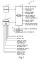
- Fig. 1 is a block diagram depicting an example system for monitoring deterioration of a rechargeable battery.
- Fig. 2 is a graph illustrating how the capacity of a rechargeable battery deteriorates at different rates depending on the rate of charge or discharge.
- Fig. 3 is a flow diagram depicting an example method for monitoring deterioration of a rechargeable battery.
- Figs. 4-8 depict example displays relating to the deterioration of a battery performance characteristic.
- Fig. 9 is a block diagram of another example system for monitoring the deterioration of a rechargeable battery.
- Fig. 10 is a block diagram of an example mobile device that may include a system for monitoring battery deterioration.
- Fig. 11 depicts an example in which both the battery monitoring system and the data store are integral to the rechargeable battery.
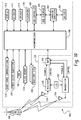
- Fig. 1 is a block diagram depicting an example system 10 for monitoring deterioration of a rechargeable battery.
- the system includes a battery monitoring system 12, a rechargeable battery 14, a data store 16, and a display 18.
- the system 10 depicted in Fig. 1 may, for example, be included in a mobile device, such as a cellular telephone, PDA or laptop computer. It should be understood, however, that the system 10 may also be used in other types of systems or devices that utilize a rechargeable battery.
- the battery monitoring system 12 may include one or more processing devices, such as a microprocessor or DSP, and may also include one or more sensor devices for detecting operating parameters of the battery 14.
- the battery monitoring system 12 may include sensor devices to detect the ambient temperature of the battery, the charge or discharge current of the battery, the battery voltage, and/or other operating parameters.
- the battery monitoring system 12 may be incorporated into the charging subsystem of a mobile device ( see, e.g., Fig. 10 ). In other examples, however, the battery monitoring system 12 may be separate from other device systems or subsystems.
- the data store 16 may be any type of non-volatile data storage device, such as a flash memory or other memory device.
- the dotted line between the rechargeable battery 14 and the data store 16 indicates that the data store 16 is associated with the battery 14.
- the data store 16 may be physically attached or internal to the rechargeable battery 14. In this manner, the stored information relating to the rechargeable battery 14 may be maintained even if the rechargeable battery 14 is moved from one system or device to another.
- battery deterioration relates to the amount by which one or more battery performance characteristics, such as the rechargeable battery's ability to store and/or deliver a charge, have diminished over time. Battery deterioration may be caused by one or more factors that are monitored by the battery monitoring system 12 to determine the present deterioration of a battery performance characteristic. As illustrated, the battery performance characteristics may include the battery's charge capacity and/or equivalent series resistance (ESR). Both of these battery performance characteristics (capacity and ESR) are subject to deterioration over time.
- ESR equivalent series resistance
- the deterioration of a rechargeable battery over time is caused by the combination of numerous environmental and operational factors.
- An exact calculation relating to the percent deterioration of a battery performance characteristic should take all of these factors into account, and is therefore not feasible (if even possible) for most applications.
- a close approximation of the percent deterioration of a battery performance characteristic may be achieved by monitoring the factors that most dramatically affect its deterioration. As illustrated in Fig. 1 , several of these factors include the age of the battery, the rate at which the battery is charged and/or discharged, the total number of charge and/or discharge cycles incurred by the battery and whether these cycles were full or partial, the battery temperature, and the charge level at which the battery is stored when not in use.
- the battery monitoring system 12 may determine an amount of deterioration of a battery performance characteristic based, at least in part, on the number of charge cycles incurred by the battery 14 and the degree to which each of the charge cycles are full charge cycles or partial charge cycles. For instance, each time the battery 14 is charged, the battery monitoring system 12 may increment a count of the number of charge cycles stored in the data store 16. In addition, the battery monitoring system 12 may monitor whether the battery is fully or partially charged and include this information in the data store 16 along with the charge cycle count.
- the stored information relating to the number of full and partial charge cycles may then be used by the battery monitoring system 12 to determine the percent deterioration of a battery performance characteristic, for example by using a stored deterioration look-up table or algorithm that is specific to the type of battery 14.
- the battery monitoring system 12 may utilize an algorithm or look-up table that associates a certain percentage of battery deterioration to every charge or discharge cycle incurred by the battery 14. The percentage of battery deterioration associated with a charge or discharge cycle may then be weighted by a predetermined amount depending on whether the charge or discharge cycle was full or partial. Even further, different weighting factors may be applied to the deterioration calculation depending on the degree to which the battery is charged or discharged during a cycle (e.g. , weight A for a quarter charge, weight B for a half charge, weight C for a three-quarter charge, and weight D for a full charge).
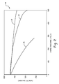
- Fig. 2 is a graph 20 illustrating how the capacity of a rechargeable battery deteriorates at different rates depending on the rate of charge or discharge.
- the uppermost curve 22 depicts battery capacity deterioration over 500 charge or discharge cycles at a slow charge and discharge rate
- curves 24 and 26 depict battery capacity deterioration at increasingly faster charge/discharge rates (with curve 26 representing the fastest of the three rates).
- the rate at which the battery deteriorates may be substantially affected by the charge and discharge rates.
- the rate at which the battery is charged and/or discharged may be included in the information monitored by the battery monitoring system 12 to determine the percent battery deterioration at a given time.
- the battery monitoring system 12 may store an aggregate average charge and discharge rate for the battery 14.
- the percentage of battery deterioration that the battery monitoring system 12 attributes to a charge or discharge cycle may then be weighted by a predetermined amount depending on the stored charge or discharge rate.
- This weighting parameter may, for example, be applied in addition to one or more other weighting factors (e.g. , weighting for partial charge/discharge cycles).
- the battery monitoring system 12 may also account for battery deterioration during periods when the battery is not in use. With reference again to Fig. 1 , the battery monitoring system 12 may, for example, track the battery age and storage temperature and incorporate these parameters into the overall battery deterioration calculation. A battery 12 will typically deteriorate more quickly when stored at higher temperatures. The age of the battery 14 along with the storage temperature data may thus be used to approximate how much the battery has deteriorated due to storage. This deterioration value may then be combined with the deterioration resulting from charge and discharge cycles to provide a more accurate approximation of battery deterioration.
- the age of the battery 14 may, for example, be tracked using an internal system clock or with reference to external data, such as a wireless network time.
- the temperature data may be detected and recorded by the battery monitoring system 12, or alternatively may be detected and recorded by a temperature sensing circuit on the battery itself. For instance, temperature sensors on the battery 14 may periodically record an average temperature value to the data store 16.
- the battery monitoring system 12 may also monitor and record the charge level at which the battery is stored (i.e., the charge level when the battery is not being charged or discharged). For example, it is known that a LiIon battery that is stored with a partial charge deteriorates more slowly than a battery that is stored with a full charge. Therefore, storage charge level information may be used along with the battery age and storage temperature information to determine an even closer approximation of battery deterioration.
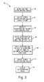
- Fig. 3 is a flow diagram depicting an example method 30 for monitoring deterioration of a rechargeable battery.
- the method detects a deterioration event for a rechargeable battery.
- the deterioration event may include either a charge cycle or a discharge cycle, where a charge cycle is detected when the battery receives a charge for a period of time and a discharge cycle is detected when the battery is discharged for a period of time.
- the deterioration event may also include a storage cycle, which is a period of time during which the battery is not being charged or discharged.
- the method 30 accesses a data store at step 34 to determine the last calculated deterioration value for one or more battery performance characteristics, such as battery capacity or ESR.
- a stored deterioration value relating to battery capacity may indicate that the maximum available storage capacity of the battery has deteriorated to a certain percentage of its original value when last calculated.
- the method identifies one or more environmental or operational factors affecting the amount of deterioration caused by the battery deterioration event. For example, if the detected battery deterioration event is a charge cycle, then the method may determine whether the charge cycle is full or partial, the rate at which the battery is charged during the charge cycle, the age of the battery during the charge cycle, and/or other factors relevant to the amount of battery deterioration incurred during a charge cycle.
- the method accesses an algorithm or look-up table from memory for use in determining the amount of deterioration caused by the event. For instance, the method may select an algorithm or look-up table that is specific to the type of battery (e.g. , the battery's chemical composition) and/or the type of deterioration event. In addition, different algorithms or look-up tables may be selected depending on one or more of the detected deterioration factors, such as the age of the battery, the temperature during the deterioration event and/or other factors. It should be understood that the number of stored algorithms or look-up tables and the number of dimensions in each algorithm or look-up table is a design choice that may be modified depending on the processing capabilities of the system and/or other design criteria.
- all of the available battery deterioration events and battery deterioration factors could be incorporated into a single multi-dimensional look-up table.
- multiple look-up tables or algorithms could be used to reduce the number of dimensions in each.
- the selected algorithm or look-up table is applied in step 40, and the updated deterioration value is stored to memory in step 42 and displayed in step 44.
- the selected algorithm or look-up table may be used to determine that the event resulted in a certain percentage of additional deterioration to the relevant battery performance characteristics. This amount may then be added to the previously stored percent deterioration and displayed on the device.
- Example displays relating to the deterioration of a battery performance characteristic are illustrated in Figs. 4-8 .
- the displays shown in Figs. 4-8 are visual presentations that may, for example, be presented on the battery deterioration display 18 of Fig. 1 .
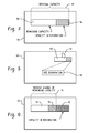
- Fig. 4 illustrates an example display 50 showing the amount that a battery's maximum capacity has deteriorated over time from its original value.
- a graphic 52 is displayed to indicate the original capacity of the battery and to show the remaining capacity 54.
- a portion of the graphic 56 is grayed out to indicate the amount by which the capacity has deteriorated.
- the remaining capacity 54 represents the total amount of energy that may be stored by the battery when fully charged, and the capacity deterioration 56 represents the amount by which the battery's full-charge capacity has degraded over time.
- FIG. 5 Another example of a display 60 showing the deterioration of a battery performance characteristic is illustrated in Fig. 5 .
- a graphic 62 showing the amount of battery deterioration is displayed on a portion of the display area 60.
- a text box 66 is displayed that indicates the percent deterioration shown on the deterioration graphic 62.
- Fig. 6 depicts an example display 70 that shows both the amount of battery deterioration and the present charge of the battery.
- the portion 72 to the far right of the graphic is blacked out to indicate the capacity deterioration of the battery.
- the entire portion 74 of the graphic to the left of the blacked out portion 72 represents the remaining capacity of the battery.
- a portion 76 is grayed out to show the present charge on the battery. That is, the portion 78 of the graphic that his neither blacked out nor grayed out represents the present charge on the battery.
- Figs. 7 and 8 depict example displays 80, 90 that provide warning messages to a user based on the deterioration status of a battery performance characteristic.
- the battery capacity has deteriorated to approximately 20% of its original capacity, as indicated by the deterioration status bar 82.
- a warning message 84 is displayed to the user.
- the message 84 advises the user that the full-charge capacity of the battery has deteriorated to an extent that only 20 hours of standby time and 12 minutes of talk time are available when the battery is fully charged.
- the message 84 therefore recommends replacing the battery.
- the warning message 84 may be generated when the battery capacity deteriorates below a predetermined threshold.
- Fig. 8 illustrates another example based on the deterioration of the battery's ESR.
- the status bar 92 shows that the ESR of the battery has deteriorated to a predetermined threshold level 94.
- the predetermined threshold is an ESR level below which an operation of the device will not properly function.
- a wireless mobile device such as a cellular telephone
- the minimum ESR threshold 94 may therefore represent the ESR value below which the battery in a wireless device will not have sufficient inrush current to operate the device.
- a warning message 96 is generated indicating that the battery must be replaced.
- Fig. 9 is a block diagram of another example system 100 for monitoring the deterioration of a rechargeable battery.
- the battery monitoring system 102 predicts the remaining life of the battery by monitoring one or more battery deterioration events as well as monitoring the usage habits of the device owner.
- the battery monitoring system 102 may record deterioration information to the data store 104, such as the number of charge and discharge cycles of the battery, whether the charge and discharge cycles where full or partial, and/or other environmental or operational factors that are relevant to the deterioration of the battery over time.
- the battery monitoring system 102 may track the usage habits of the device owner, such as how often the battery is charged on average, the average amount that the battery is discharged before being charged, and/or other usage information that is relevant to battery deterioration. The stored battery usage habit information may then be used along with the deterioration information to predict the amount of time remaining before the battery will need to be replaced.
- Fig. 10 is a block diagram of an example mobile device 200 that may include a system for monitoring battery deterioration.
- the mobile device 200 includes a charging subsystem 202 and a rechargeable battery 204.
- the charging subsystem 202 may include a battery monitoring system, as described herein.
- the rechargeable battery 204 may include an integrated memory device for storing battery deterioration information and/or other information pertaining to the battery 204.
- the mobile device 200 may also include a processing device 206, a communications subsystem 208, a short-range communications subsystem 210, input/output devices 212-215, memory devices 216, 218, a USB interface 220 and USB controller 22, and various other device subsystems 224.
- the charging subsystem 202 charges the rechargeable battery 204 and provides power to the mobile device 200, either from the rechargeable battery 204 or from a USB host connected to the USB interface 220.
- the USB controller 222 monitors the USB data lines, and controls data communication between the processing device 206 and a USB host.
- the processing device 206 controls the overall operation of the mobile device 200.
- Operating system software executed by the processing device 206 is preferably stored in a persistent store such as a flash memory 218, but may also be stored in other types of memory devices, such as a read only memory (ROM) or similar storage element.
- ROM read only memory
- operating system software, specific device applications, or parts thereof may be temporarily loaded into a volatile store, such as a random access memory (RAM) 216.
- Communication signals received by the mobile device 200 may also be stored to RAM 216.
- the processing device 206 in addition to its operating system functions, enables execution of software applications on the device 200.
- a predetermined set of applications that control basic device operations, such as data and voice communications, may be installed on the device 200 during manufacture.
- a personal information manager (PIM) application may be installed during manufacture.
- the PIM is preferably capable of organizing and managing data items, such as e-mail, calendar events, voice mails, appointments, and task items.
- the PIM application is also preferably capable of sending and receiving data items via the wireless network 226.
- the PIM data items are seamlessly integrated, synchronized and updated via the wireless network 226 with the device user's corresponding data items stored or associated with a host computer system.
- Communication functions are performed through the communication subsystem 208, and possibly through the short-range communications subsystem 210.
- the communication subsystem 200 includes a receiver 228, a transmitter 230, and a processing module 232, such as a digital signal processor (DSP).
- the communication subsystem 208 configured as a two-way communications device, includes one or more, preferably embedded or internal, antenna elements 234, 236, and local oscillators (LOs) 238.
- the specific design and implementation of the communication subsystem 208 is dependent upon the communication network 226 in which the mobile device 200 is intended to operate. Network access requirements vary depending upon the type of communication system 226.
- the mobile device 200 may send and receive communication signals over the communication network 226.
- Signals received by the antenna 234 through the communication network 226 are input to the receiver 228, which may perform such common receiver functions as signal amplification, frequency down-conversion, filtering, channel selection, and analog-to-digital conversion. Analog-to-digital conversion of the received signal allows the DSP to perform more complex communication functions, such as demodulation and decoding.
- signals to be transmitted are processed by the DSP 232, and are then input to the transmitter 230 for digital-to-analog conversion, frequency up-conversion, filtering, amplification and transmission over the communication network 208 via the antenna 236.
- the DSP 232 provides for receiver 228 and transmitter 230 control. For example, gains applied to communication signals in the receiver 228 and transmitter 230 may be adaptively controlled through automatic gain control algorithms implemented in the DSP 232.
- a received signal such as a text message or web page download
- the received signal is then further processed by the processing device 206 for output to a display 212 (which may serve the function of the battery deterioration display 18 of Fig. 1 ), or alternatively to some other auxiliary I/O device 238.
- a device user may also compose data items, such as e-mail messages, using a keyboard 213, such as a QWERTY-style keyboard, and/or some other auxiliary I/O device 238, such as a touchpad, a rocker switch, a thumb-wheel, or some other type of input device.
- the composed data items may then be transmitted over the communication network 226 via the communication subsystem 208.
- a voice communication mode In a voice communication mode, overall operation of the device 200 is substantially similar to data communication mode, except that received signals are output to a speaker 214, and signals for transmission are generated by a microphone 215.
- Alternative voice or audio I/O subsystems such as a voice message recording subsystem, may also be implemented on the device 200.
- the display 212 may also be utilized in voice communication mode, for example to display the identity of a calling party, the duration of a voice call, or other voice call related information.
- the short-range communications subsystem 210 enables communication between the mobile device 200 and other proximate systems or devices, which need not necessarily be similar devices.
- the short-range communications subsystem 210 may include an infrared device and associated circuits and components, or a BluetoothTM communication module to provide for communication with similarly-enabled systems and devices.
- Fig. 11 depicts an example in which both the battery monitoring system 302 and the data store 304 are integral to the rechargeable battery 300. With an integral battery monitoring system 302, information relating to the storage and possibly charging of the battery 300 may be monitored and recorded even when the battery 300 has not been inserted into a mobile device.
- the integral battery monitoring system 302 may communicate with systems within the mobile device to monitor charging, discharging and storage information and to cause information relating to battery deterioration to be displayed on the mobile device, as described above.
- portions of the battery monitoring system may be included in the rechargeable battery and other portions may be included in the mobile device.
Abstract
Description
- This application claims priority from
U.S. Provisional Patent Application No. 61/086,985, filed on August 7, 2008 - The technology described in this patent document relates generally to systems and devices that utilize a rechargeable battery. More particularly, systems and methods are provided for monitoring the deterioration of a rechargeable battery.
- The deterioration of a rechargeable battery relates to the amount that one or more performance characteristics of the battery have degraded over time. The battery performance characteristics that are subject to deterioration include, for example, the charge capacity of the battery and the battery's equivalent series resistance (ESR). The charge capacity of the battery is a measure of the amount of energy that may be stored in the battery when fully charged. The ESR of the battery is relevant to determining the amount of current that the battery is capable of delivering. It is desirable in many systems and devices to monitor the deterioration of one or more battery performance characteristics, for instance, to determine when the rechargeable battery should be replaced.
-
Fig. 1 is a block diagram depicting an example system for monitoring deterioration of a rechargeable battery. -
Fig. 2 is a graph illustrating how the capacity of a rechargeable battery deteriorates at different rates depending on the rate of charge or discharge. -
Fig. 3 is a flow diagram depicting an example method for monitoring deterioration of a rechargeable battery. -
Figs. 4-8 depict example displays relating to the deterioration of a battery performance characteristic. -
Fig. 9 is a block diagram of another example system for monitoring the deterioration of a rechargeable battery. -
Fig. 10 is a block diagram of an example mobile device that may include a system for monitoring battery deterioration. -
Fig. 11 depicts an example in which both the battery monitoring system and the data store are integral to the rechargeable battery. -
Fig. 1 is a block diagram depicting anexample system 10 for monitoring deterioration of a rechargeable battery. The system includes abattery monitoring system 12, arechargeable battery 14, adata store 16, and adisplay 18. Thesystem 10 depicted inFig. 1 may, for example, be included in a mobile device, such as a cellular telephone, PDA or laptop computer. It should be understood, however, that thesystem 10 may also be used in other types of systems or devices that utilize a rechargeable battery. - The
battery monitoring system 12 may include one or more processing devices, such as a microprocessor or DSP, and may also include one or more sensor devices for detecting operating parameters of thebattery 14. For example, thebattery monitoring system 12 may include sensor devices to detect the ambient temperature of the battery, the charge or discharge current of the battery, the battery voltage, and/or other operating parameters. In one example, thebattery monitoring system 12 may be incorporated into the charging subsystem of a mobile device (see, e.g.,Fig. 10 ). In other examples, however, thebattery monitoring system 12 may be separate from other device systems or subsystems. - The
data store 16 may be any type of non-volatile data storage device, such as a flash memory or other memory device. The dotted line between therechargeable battery 14 and thedata store 16 indicates that thedata store 16 is associated with thebattery 14. In one embodiment, for example, thedata store 16 may be physically attached or internal to therechargeable battery 14. In this manner, the stored information relating to therechargeable battery 14 may be maintained even if therechargeable battery 14 is moved from one system or device to another. - In operation, data relating to the deterioration of the
rechargeable battery 14 is monitored by thebattery monitoring system 12 and stored in thedata store 16. Thebattery monitoring system 12 may also cause information relating to the battery deterioration to be shown on thedisplay 18. Battery deterioration relates to the amount by which one or more battery performance characteristics, such as the rechargeable battery's ability to store and/or deliver a charge, have diminished over time. Battery deterioration may be caused by one or more factors that are monitored by thebattery monitoring system 12 to determine the present deterioration of a battery performance characteristic. As illustrated, the battery performance characteristics may include the battery's charge capacity and/or equivalent series resistance (ESR). Both of these battery performance characteristics (capacity and ESR) are subject to deterioration over time. - The deterioration of a rechargeable battery over time is caused by the combination of numerous environmental and operational factors. An exact calculation relating to the percent deterioration of a battery performance characteristic should take all of these factors into account, and is therefore not feasible (if even possible) for most applications. However, a close approximation of the percent deterioration of a battery performance characteristic may be achieved by monitoring the factors that most dramatically affect its deterioration. As illustrated in
Fig. 1 , several of these factors include the age of the battery, the rate at which the battery is charged and/or discharged, the total number of charge and/or discharge cycles incurred by the battery and whether these cycles were full or partial, the battery temperature, and the charge level at which the battery is stored when not in use. - In one example, the
battery monitoring system 12 may determine an amount of deterioration of a battery performance characteristic based, at least in part, on the number of charge cycles incurred by thebattery 14 and the degree to which each of the charge cycles are full charge cycles or partial charge cycles. For instance, each time thebattery 14 is charged, thebattery monitoring system 12 may increment a count of the number of charge cycles stored in thedata store 16. In addition, thebattery monitoring system 12 may monitor whether the battery is fully or partially charged and include this information in thedata store 16 along with the charge cycle count. The stored information relating to the number of full and partial charge cycles may then be used by thebattery monitoring system 12 to determine the percent deterioration of a battery performance characteristic, for example by using a stored deterioration look-up table or algorithm that is specific to the type ofbattery 14. - For instance, the
battery monitoring system 12 may utilize an algorithm or look-up table that associates a certain percentage of battery deterioration to every charge or discharge cycle incurred by thebattery 14. The percentage of battery deterioration associated with a charge or discharge cycle may then be weighted by a predetermined amount depending on whether the charge or discharge cycle was full or partial. Even further, different weighting factors may be applied to the deterioration calculation depending on the degree to which the battery is charged or discharged during a cycle (e.g., weight A for a quarter charge, weight B for a half charge, weight C for a three-quarter charge, and weight D for a full charge). - The accuracy of the battery deterioration calculated by the
battery monitoring system 12 may be improved by adding further dimensions to the look-up table or algorithm that take into consideration additional environmental or operational factors. For example,Fig. 2 is agraph 20 illustrating how the capacity of a rechargeable battery deteriorates at different rates depending on the rate of charge or discharge. In thegraph 20, theuppermost curve 22 depicts battery capacity deterioration over 500 charge or discharge cycles at a slow charge and discharge rate, andcurves curve 26 representing the fastest of the three rates). As illustrated, the rate at which the battery deteriorates may be substantially affected by the charge and discharge rates. Accordingly, the rate at which the battery is charged and/or discharged may be included in the information monitored by thebattery monitoring system 12 to determine the percent battery deterioration at a given time. For instance, thebattery monitoring system 12 may store an aggregate average charge and discharge rate for thebattery 14. The percentage of battery deterioration that thebattery monitoring system 12 attributes to a charge or discharge cycle may then be weighted by a predetermined amount depending on the stored charge or discharge rate. This weighting parameter may, for example, be applied in addition to one or more other weighting factors (e.g., weighting for partial charge/discharge cycles). - In addition to monitoring operational and environmental factors during charge and discharge cycles, the
battery monitoring system 12 may also account for battery deterioration during periods when the battery is not in use. With reference again toFig. 1 , thebattery monitoring system 12 may, for example, track the battery age and storage temperature and incorporate these parameters into the overall battery deterioration calculation. Abattery 12 will typically deteriorate more quickly when stored at higher temperatures. The age of thebattery 14 along with the storage temperature data may thus be used to approximate how much the battery has deteriorated due to storage. This deterioration value may then be combined with the deterioration resulting from charge and discharge cycles to provide a more accurate approximation of battery deterioration. The age of thebattery 14 may, for example, be tracked using an internal system clock or with reference to external data, such as a wireless network time. The temperature data may be detected and recorded by thebattery monitoring system 12, or alternatively may be detected and recorded by a temperature sensing circuit on the battery itself. For instance, temperature sensors on thebattery 14 may periodically record an average temperature value to thedata store 16. - In another example, the
battery monitoring system 12 may also monitor and record the charge level at which the battery is stored (i.e., the charge level when the battery is not being charged or discharged). For example, it is known that a LiIon battery that is stored with a partial charge deteriorates more slowly than a battery that is stored with a full charge. Therefore, storage charge level information may be used along with the battery age and storage temperature information to determine an even closer approximation of battery deterioration. -
Fig. 3 is a flow diagram depicting anexample method 30 for monitoring deterioration of a rechargeable battery. Atstep 32, the method detects a deterioration event for a rechargeable battery. The deterioration event may include either a charge cycle or a discharge cycle, where a charge cycle is detected when the battery receives a charge for a period of time and a discharge cycle is detected when the battery is discharged for a period of time. In addition, the deterioration event may also include a storage cycle, which is a period of time during which the battery is not being charged or discharged. - When a battery deterioration event is detected, the
method 30 accesses a data store atstep 34 to determine the last calculated deterioration value for one or more battery performance characteristics, such as battery capacity or ESR. For example, a stored deterioration value relating to battery capacity may indicate that the maximum available storage capacity of the battery has deteriorated to a certain percentage of its original value when last calculated. - In
step 36, the method identifies one or more environmental or operational factors affecting the amount of deterioration caused by the battery deterioration event. For example, if the detected battery deterioration event is a charge cycle, then the method may determine whether the charge cycle is full or partial, the rate at which the battery is charged during the charge cycle, the age of the battery during the charge cycle, and/or other factors relevant to the amount of battery deterioration incurred during a charge cycle. - In
step 38, the method accesses an algorithm or look-up table from memory for use in determining the amount of deterioration caused by the event. For instance, the method may select an algorithm or look-up table that is specific to the type of battery (e.g., the battery's chemical composition) and/or the type of deterioration event. In addition, different algorithms or look-up tables may be selected depending on one or more of the detected deterioration factors, such as the age of the battery, the temperature during the deterioration event and/or other factors. It should be understood that the number of stored algorithms or look-up tables and the number of dimensions in each algorithm or look-up table is a design choice that may be modified depending on the processing capabilities of the system and/or other design criteria. For instance, in one example all of the available battery deterioration events and battery deterioration factors could be incorporated into a single multi-dimensional look-up table. In other examples, however, multiple look-up tables or algorithms could be used to reduce the number of dimensions in each. - The selected algorithm or look-up table is applied in
step 40, and the updated deterioration value is stored to memory instep 42 and displayed instep 44. For example, the selected algorithm or look-up table may be used to determine that the event resulted in a certain percentage of additional deterioration to the relevant battery performance characteristics. This amount may then be added to the previously stored percent deterioration and displayed on the device. - Example displays relating to the deterioration of a battery performance characteristic are illustrated in
Figs. 4-8 . The displays shown inFigs. 4-8 are visual presentations that may, for example, be presented on thebattery deterioration display 18 ofFig. 1 .Fig. 4 illustrates anexample display 50 showing the amount that a battery's maximum capacity has deteriorated over time from its original value. In this example, a graphic 52 is displayed to indicate the original capacity of the battery and to show the remainingcapacity 54. A portion of the graphic 56 is grayed out to indicate the amount by which the capacity has deteriorated. The remainingcapacity 54 represents the total amount of energy that may be stored by the battery when fully charged, and thecapacity deterioration 56 represents the amount by which the battery's full-charge capacity has degraded over time. - Another example of a
display 60 showing the deterioration of a battery performance characteristic is illustrated inFig. 5 . In this example, a graphic 62 showing the amount of battery deterioration is displayed on a portion of thedisplay area 60. When the user moves acursor 64 over the graphic 62, atext box 66 is displayed that indicates the percent deterioration shown on the deterioration graphic 62. -
Fig. 6 depicts anexample display 70 that shows both the amount of battery deterioration and the present charge of the battery. In this example, theportion 72 to the far right of the graphic is blacked out to indicate the capacity deterioration of the battery. Theentire portion 74 of the graphic to the left of the blacked outportion 72 represents the remaining capacity of the battery. Of this remainingcapacity 74, aportion 76 is grayed out to show the present charge on the battery. That is, theportion 78 of the graphic that his neither blacked out nor grayed out represents the present charge on the battery. -
Figs. 7 and 8 depict example displays 80, 90 that provide warning messages to a user based on the deterioration status of a battery performance characteristic. In the example shown inFig. 8 , the battery capacity has deteriorated to approximately 20% of its original capacity, as indicated by thedeterioration status bar 82. As a result of the substantial deterioration to the battery capacity, awarning message 84 is displayed to the user. In this example, themessage 84 advises the user that the full-charge capacity of the battery has deteriorated to an extent that only 20 hours of standby time and 12 minutes of talk time are available when the battery is fully charged. Themessage 84 therefore recommends replacing the battery. Thewarning message 84 may be generated when the battery capacity deteriorates below a predetermined threshold. -
Fig. 8 illustrates another example based on the deterioration of the battery's ESR. In this example, thestatus bar 92 shows that the ESR of the battery has deteriorated to apredetermined threshold level 94. The predetermined threshold is an ESR level below which an operation of the device will not properly function. For example, a wireless mobile device, such as a cellular telephone, requires a certain minimum amount of current (mA) from the battery in order to operate. Theminimum ESR threshold 94 may therefore represent the ESR value below which the battery in a wireless device will not have sufficient inrush current to operate the device. When the ESR deterioration reaches thispredetermined threshold 94, awarning message 96 is generated indicating that the battery must be replaced. -
Fig. 9 is a block diagram of anotherexample system 100 for monitoring the deterioration of a rechargeable battery. In this example, thebattery monitoring system 102 predicts the remaining life of the battery by monitoring one or more battery deterioration events as well as monitoring the usage habits of the device owner. For example, thebattery monitoring system 102 may record deterioration information to the data store 104, such as the number of charge and discharge cycles of the battery, whether the charge and discharge cycles where full or partial, and/or other environmental or operational factors that are relevant to the deterioration of the battery over time. In addition, thebattery monitoring system 102 may track the usage habits of the device owner, such as how often the battery is charged on average, the average amount that the battery is discharged before being charged, and/or other usage information that is relevant to battery deterioration. The stored battery usage habit information may then be used along with the deterioration information to predict the amount of time remaining before the battery will need to be replaced. -
Fig. 10 is a block diagram of an examplemobile device 200 that may include a system for monitoring battery deterioration. Themobile device 200 includes acharging subsystem 202 and arechargeable battery 204. Thecharging subsystem 202 may include a battery monitoring system, as described herein. In addition, therechargeable battery 204 may include an integrated memory device for storing battery deterioration information and/or other information pertaining to thebattery 204. Themobile device 200 may also include aprocessing device 206, acommunications subsystem 208, a short-range communications subsystem 210, input/output devices 212-215,memory devices USB interface 220 andUSB controller 22, and variousother device subsystems 224. - In addition to monitoring battery deterioration, the
charging subsystem 202 charges therechargeable battery 204 and provides power to themobile device 200, either from therechargeable battery 204 or from a USB host connected to theUSB interface 220. TheUSB controller 222 monitors the USB data lines, and controls data communication between theprocessing device 206 and a USB host. - The
processing device 206 controls the overall operation of themobile device 200. Operating system software executed by theprocessing device 206 is preferably stored in a persistent store such as aflash memory 218, but may also be stored in other types of memory devices, such as a read only memory (ROM) or similar storage element. In addition, operating system software, specific device applications, or parts thereof, may be temporarily loaded into a volatile store, such as a random access memory (RAM) 216. Communication signals received by themobile device 200 may also be stored toRAM 216. - The
processing device 206, in addition to its operating system functions, enables execution of software applications on thedevice 200. A predetermined set of applications that control basic device operations, such as data and voice communications, may be installed on thedevice 200 during manufacture. In addition, a personal information manager (PIM) application may be installed during manufacture. The PIM is preferably capable of organizing and managing data items, such as e-mail, calendar events, voice mails, appointments, and task items. The PIM application is also preferably capable of sending and receiving data items via thewireless network 226. Preferably, the PIM data items are seamlessly integrated, synchronized and updated via thewireless network 226 with the device user's corresponding data items stored or associated with a host computer system. - Communication functions, including data and voice communications, are performed through the
communication subsystem 208, and possibly through the short-range communications subsystem 210. If themobile device 200 is enabled for two-way communications, then thecommunication subsystem 200 includes areceiver 228, atransmitter 230, and aprocessing module 232, such as a digital signal processor (DSP). In addition, thecommunication subsystem 208, configured as a two-way communications device, includes one or more, preferably embedded or internal,antenna elements communication subsystem 208 is dependent upon thecommunication network 226 in which themobile device 200 is intended to operate. Network access requirements vary depending upon the type ofcommunication system 226. - When required network registration or activation procedures have been completed, the
mobile device 200 may send and receive communication signals over thecommunication network 226. Signals received by theantenna 234 through thecommunication network 226 are input to thereceiver 228, which may perform such common receiver functions as signal amplification, frequency down-conversion, filtering, channel selection, and analog-to-digital conversion. Analog-to-digital conversion of the received signal allows the DSP to perform more complex communication functions, such as demodulation and decoding. In a similar manner, signals to be transmitted are processed by theDSP 232, and are then input to thetransmitter 230 for digital-to-analog conversion, frequency up-conversion, filtering, amplification and transmission over thecommunication network 208 via theantenna 236. - In addition to processing communication signals, the
DSP 232 provides forreceiver 228 andtransmitter 230 control. For example, gains applied to communication signals in thereceiver 228 andtransmitter 230 may be adaptively controlled through automatic gain control algorithms implemented in theDSP 232. - In a data communication mode, a received signal, such as a text message or web page download, is processed by the
communication subsystem 208 and input to theprocessing device 206. The received signal is then further processed by theprocessing device 206 for output to a display 212 (which may serve the function of thebattery deterioration display 18 ofFig. 1 ), or alternatively to some other auxiliary I/O device 238. A device user may also compose data items, such as e-mail messages, using akeyboard 213, such as a QWERTY-style keyboard, and/or some other auxiliary I/O device 238, such as a touchpad, a rocker switch, a thumb-wheel, or some other type of input device. The composed data items may then be transmitted over thecommunication network 226 via thecommunication subsystem 208. - In a voice communication mode, overall operation of the
device 200 is substantially similar to data communication mode, except that received signals are output to aspeaker 214, and signals for transmission are generated by amicrophone 215. Alternative voice or audio I/O subsystems, such as a voice message recording subsystem, may also be implemented on thedevice 200. In addition, thedisplay 212 may also be utilized in voice communication mode, for example to display the identity of a calling party, the duration of a voice call, or other voice call related information. - The short-
range communications subsystem 210 enables communication between themobile device 200 and other proximate systems or devices, which need not necessarily be similar devices. For example, the short-range communications subsystem 210 may include an infrared device and associated circuits and components, or a Bluetooth™ communication module to provide for communication with similarly-enabled systems and devices. - This written description uses examples to disclose the invention, including the best mode, and also to enable a person skilled in the art to make and use the invention. The invention described herein may provide certain advantages, such as a more accurate approximation of battery deterioration, an enhanced information display for the benefit of the user, and/or other advantages. The patentable scope of the invention may include other examples that occur to those skilled in the art. For example,
Fig. 11 depicts an example in which both thebattery monitoring system 302 and thedata store 304 are integral to therechargeable battery 300. With an integralbattery monitoring system 302, information relating to the storage and possibly charging of thebattery 300 may be monitored and recorded even when thebattery 300 has not been inserted into a mobile device. When therechargeable battery 300 is inserted into a mobile device, the integralbattery monitoring system 302 may communicate with systems within the mobile device to monitor charging, discharging and storage information and to cause information relating to battery deterioration to be displayed on the mobile device, as described above. In other examples, portions of the battery monitoring system may be included in the rechargeable battery and other portions may be included in the mobile device. - Aspects and features of the present disclosure are set forth in the following numbered clauses which correspond to the claims of the parent application as filed:
-
- 1. A mobile device, comprising:
- a rechargeable battery;
- a data store; and
- a battery monitoring system configured to store charging information, discharge information and storage information to the data store, the charging information including a number of charge cycles incurred by the rechargeable battery, the discharge information including a number discharge cycles incurred by the rechargeable battery, and the storage information including information relating to periods when the rechargeable battery is not being actively charged or discharged;
- the battery monitoring system being further configured to determine an amount of deterioration of a battery performance characteristic based on the stored charging information, discharge information and storage information.
- 2. The mobile device of clause 1, wherein the charging information includes information indicating whether each of the charge cycles were full charge cycles or partial charge cycles.
- 3. The mobile device of clause 2, wherein the charging information further indicates a degree to which the rechargeable battery was charged during the partial charge cycles.
- 4. The mobile device of clause 1, wherein the storage information includes information relating to temperature during storage periods.
- 5. The mobile device of clause 1, wherein the storage information includes information relating to charge level during storage periods.
- 6. The mobile device of clause 1, wherein at least one of the charging information, discharge information and storage information includes information indicating an age of the rechargeable battery.
- 7. The mobile device of clause 1, wherein the charging information includes information relating to a rate of charge during the charge cycles.
- 8. The mobile device of clause 1, wherein the charging information includes information relating to a rate of discharge during the discharge cycles.
- 9. The mobile device of clause 1, wherein the battery performance characteristic is battery capacity.
- 10. The mobile device of clause 1, wherein the battery performance characteristic is equivalent series resistance (ESR).
- 11. The mobile device of clause 1, wherein the amount of deterioration is determined using a look-up table stored in the data store.
- 12. The mobile device of clause 13, wherein he look-up table is specific to a chemical composition of the rechargeable battery
- 13. The mobile device of clause 1, wherein the battery monitoring system is further configured to output information relating to the amount of deterioration of the battery performance characteristic, the output information being used to generate a graphical display on a display device.
- 14. The mobile device of clause 13, wherein the graphical display includes a bar graph that shows the amount of deterioration of the battery performance characteristic in relating to a remaining amount of the battery performance characteristic.
- 15. The mobile device of
clause 14, wherein the graphical display indicates when the rechargeable battery should be replaced based on the amount of deterioration of the battery performance characteristic. - 16. The mobile device of
clause 14, wherein the battery performance characteristic is battery capacity, and wherein the graphical display further indicates a present charge on the rechargeable battery. - 17. The mobile device of clause 1, wherein the battery monitoring system is further configured to monitor and record battery usage information in the data store, the battery usage information relating to usage of the rechargeable battery by a mobile device user; and
wherein the battery monitoring system predicts a remaining usable life of the rechargeable battery based on the charging information, discharge information, storage information and usage information. - 18. The mobile device of clause 17, wherein the usage information includes information relating to how often the rechargeable battery is charged on average.
- 19. The mobile device of clause 17, wherein the usage information includes information relating to an average amount that the battery is discharged before being charged.
- 20. A method for monitoring deterioration of a rechargeable battery in a mobile device, comprising:
- detecting a battery deterioration event relating to a battery performance characteristic, wherein the deterioration event may be a battery charging event, a battery discharging event or a storage period;
- monitoring at least one environmental or operational factor affecting deterioration of the battery performance characteristic from the battery deterioration event;
- accessing a stored deterioration value for the battery performance characteristic;
- determining a new deterioration value based on the stored deterioration value, the battery deterioration event and the at least one environmental or operational factor; and
- storing the new deterioration value to a memory device associated with the rechargeable battery.
- 21. The method of
clause 20, wherein the battery performance characteristic is battery capacity or equivalent series resistance (ESR). - 22. The method of
clause 20, wherein the at least one environmental or operational factor includes at least one of an average rate at which the rechargeable battery is charged, an average rate at which the rechargeable battery is discharged, whether the charging event is a full or partial charge cycle, an age of the battery, and an average temperature and charge level during the storage period. - 23. The method of
clause 20, wherein the new deterioration value is determined using a look-up table, further comprising:- selecting the look-up table from a plurality of stored look-up tables based on at least one of a battery chemistry of the rechargeable battery, the battery deterioration event and the at least one environmental or operational factor.
- 24. The method of
clause 20, wherein the new deterioration value is determined using a deterioration algorithm, further comprising:- selecting the deterioration algorithm from a plurality of stored deterioration algorithms based on at least one of a battery chemistry of the rechargeable battery, the battery deterioration event and the at least one environmental or operational factor.
- 25. The method of
clause 20, wherein the new deterioration value is determined by a method comprising:- determining a base deterioration value based on the battery deterioration event;
- weighting the base deterioration value by a weighting factor that is determined based on the at least one environmental or operational factor to generate a weighted deterioration value; and
- combining the stored deterioration value with the weighted deterioration value to generate the new deterioration value.
Claims (20)
- An electrical device configured to be powered by a battery, the electrical device including:a battery monitoring system configured to determine deterioration of capacity of the battery;a display device configured to display an image that includes:a first representation of an original capacity of the battery,a second representation of amount of deterioration of the battery capacity relative to the first representation,a third representation of undeteriorated amount of the battery capacity relative to the first representation, anda fourth representation of the present charge of the battery relative to the third representation.
- The electrical device of claim 1 wherein each of the first, second, third and fourth representations corresponds to four bar graph sections.
- The electrical device of claim 2 wherein each of the four bar graph sections are on a same status bar, such that the second and third representations' sections together comprise the first representation's section.
- The electrical device of claim 1 wherein the image further includes a fifth representation of a threshold for the second representation to reach to warrant replacing the battery.
- The electrical device of claim 4 wherein the fifth representation is a line on the image.
- The electrical device of claim 4 wherein the electrical device is configured to provide a warning when the second representation reaches the threshold.
- The electrical device of claim 1 wherein the battery monitoring system is further configured to predict a remaining usable life of the battery based on the battery's charging history, discharging history and storage history.
- The electrical device of claim 7 wherein the charging history includes how often the battery is charged on average.
- The electrical device of claim 7 wherein the discharging history includes an average amount that the battery is discharged before being charged.
- The electrical device of claim 7 wherein the battery monitoring system is configured to predict the remaining usable life based also on the battery's age.
- The electrical device of claim 1 wherein the battery monitoring system is configured to:monitor battery usage habits of a user in using the electrical device; andpredict, based on the usage habits, an amount of time remaining before the battery should be replaced.
- The electrical device of claim 11 wherein the usage habits relate to at least one of how often the battery is charged on average and an average amount that the battery is discharged before being charged.
- The electrical device of claim 1 wherein display device is further configured to display, concurrently:a first amount of battery time remaining if the electrical device is operating in a first mode; anda second amount of battery time remaining if the electrical device is operating in a second mode.
- The electrical device of claim 13 wherein the device is a communication device and the first mode is standby mode and the second mode is communication mode.
- The electrical device of claim 1 wherein the electrical device is a mobile communication device.
- An electrical device configured to be powered by a battery, the electrical device including:a battery monitoring system configured to determine deterioration of a characteristic relating to equivalent series resistance (ESR) of the battery;a display device configured to display an image that includes:a first representation of an original level of the ESR characteristic,a second representation of amount of deterioration of the ESR characteristic relative to the first representation,a third representation of undeteriorated amount of the ESR characteristic relative to the first representation, anda fourth representation of a threshold for the second representation to reach to warrant replacing the battery.
- The electrical device of claim 16 wherein each of the first, second and third representations corresponds to four bar graph sections.
- The electrical device of claim 17 wherein each of the four bar graph sections are on a same status bar, such that the second and third representations' sections together comprise the first representation's section..
- The electrical device of claim 16 wherein the fourth representation is a line on the image.
- The electrical device of claim 16 wherein the electrical device is configured to provide a warning when the second representation reaches the threshold.
Applications Claiming Priority (2)
| Application Number | Priority Date | Filing Date | Title |
|---|---|---|---|
| US8698508P | 2008-08-07 | 2008-08-07 | |
| EP09167470A EP2151694A3 (en) | 2008-08-07 | 2009-08-07 | Systems and methods for monitoring deterioration of a rechargeable battery |
Related Parent Applications (2)
| Application Number | Title | Priority Date | Filing Date |
|---|---|---|---|
| EP09167470.5 Division | 2009-08-07 | ||
| EP09167470A Division EP2151694A3 (en) | 2008-08-07 | 2009-08-07 | Systems and methods for monitoring deterioration of a rechargeable battery |
Publications (3)
| Publication Number | Publication Date |
|---|---|
| EP2568304A2 true EP2568304A2 (en) | 2013-03-13 |
| EP2568304A3 EP2568304A3 (en) | 2013-07-10 |
| EP2568304B1 EP2568304B1 (en) | 2019-02-27 |
Family
ID=41349267
Family Applications (2)
| Application Number | Title | Priority Date | Filing Date |
|---|---|---|---|
| EP12195344.2A Active EP2568304B1 (en) | 2008-08-07 | 2009-08-07 | Systems and methods for monitoring deterioration of a rechargeable battery |
| EP09167470A Ceased EP2151694A3 (en) | 2008-08-07 | 2009-08-07 | Systems and methods for monitoring deterioration of a rechargeable battery |
Family Applications After (1)
| Application Number | Title | Priority Date | Filing Date |
|---|---|---|---|
| EP09167470A Ceased EP2151694A3 (en) | 2008-08-07 | 2009-08-07 | Systems and methods for monitoring deterioration of a rechargeable battery |
Country Status (3)
| Country | Link |
|---|---|
| US (3) | US8255176B2 (en) |
| EP (2) | EP2568304B1 (en) |
| CA (1) | CA2674966C (en) |
Cited By (1)
| Publication number | Priority date | Publication date | Assignee | Title |
|---|---|---|---|---|
| CN111130223A (en) * | 2018-10-30 | 2020-05-08 | 北京小米移动软件有限公司 | Wireless charging display method and device |
Families Citing this family (60)
| Publication number | Priority date | Publication date | Assignee | Title |
|---|---|---|---|---|
| JP4265629B2 (en) * | 2006-08-01 | 2009-05-20 | トヨタ自動車株式会社 | Secondary battery charge / discharge control device and hybrid vehicle equipped with the same |
| KR100998577B1 (en) * | 2007-08-29 | 2010-12-07 | 주식회사 와튼 | Aging status diognostic equipment for power conversion system, and method their of |
| US8367235B2 (en) | 2008-01-18 | 2013-02-05 | Mophie, Inc. | Battery pack, holster, and extendible processing and interface platform for mobile devices |
| US8255176B2 (en) | 2008-08-07 | 2012-08-28 | Research In Motion Limited | Systems and methods for monitoring deterioration of a rechargeable battery |
| US8660809B2 (en) * | 2008-12-02 | 2014-02-25 | Broadcom Corporation | Method for accurate battery run time estimation utilizing adaptive offset values |
| US20100138176A1 (en) * | 2008-12-02 | 2010-06-03 | Broadcom Corporation | System for accurate battery run time estimation utilizing voltage capture and coulomb counting |
| US8200292B2 (en) * | 2009-02-26 | 2012-06-12 | Research In Motion Limited | Method and apparatus for dynamic battery management control in a mobile communication device |
| US8423238B2 (en) * | 2009-07-31 | 2013-04-16 | Thermo King Corporation | Monitoring battery health in an HVAC system |
| US20110128006A1 (en) * | 2009-12-01 | 2011-06-02 | Helix Micro | Method and apparatus for detecting battery life |
| JP4888577B2 (en) * | 2010-04-12 | 2012-02-29 | トヨタ自動車株式会社 | Non-aqueous electrolyte type lithium ion secondary battery system, method for determining lithium deposition in the system, and vehicle equipped with the system |
| US8874728B2 (en) * | 2010-08-31 | 2014-10-28 | Dell Products L.P. | System and method for customizing information handling system product and service offerings based on usage profiles |
| US8479024B2 (en) * | 2010-08-31 | 2013-07-02 | Dell Products L.P. | System and method for customizing information handling system internal power source and service offerings based on usage profiles |
| EP2629109B1 (en) * | 2010-10-14 | 2022-06-29 | Toyota Jidosha Kabushiki Kaisha | Electrical storage device |
| JP2012127744A (en) * | 2010-12-14 | 2012-07-05 | Sony Corp | Electronic apparatus, battery pack, and capacity calculation method of battery pack |
| EP2662949A4 (en) * | 2011-01-06 | 2017-04-19 | Nec Corporation | Charging control device, charging control method, and program |
| CN102608533B (en) * | 2011-01-20 | 2014-08-20 | 鸿富锦精密工业(深圳)有限公司 | System and method for testing charge-discharge reliability of battery |
| US20120210150A1 (en) * | 2011-02-10 | 2012-08-16 | Alcatel-Lucent Usa Inc. | Method And Apparatus Of Smart Power Management For Mobile Communication Terminals |
| JP5747610B2 (en) * | 2011-03-30 | 2015-07-15 | ソニー株式会社 | CHARGE CONTROL DEVICE, CHARGE CONTROL METHOD, PROGRAM, AND SYSTEM |
| US20130262002A1 (en) * | 2012-03-30 | 2013-10-03 | Mckesson Automation Inc. | Monitoring and matching batteries and battery powered devices |
| DE102012207860A1 (en) * | 2012-05-11 | 2013-11-14 | Siemens Aktiengesellschaft | Method for determining a total capacity loss of a secondary cell |
| US9312712B2 (en) * | 2012-07-26 | 2016-04-12 | Samsung Sdi Co., Ltd. | Method and system for controlling charging parameters of a battery using a plurality of temperature ranges and counters and parameter sets |
| EP2881749B1 (en) * | 2012-07-31 | 2017-01-04 | Panasonic Intellectual Property Management Co., Ltd. | Control method and control device using same |
| US20140139344A1 (en) * | 2012-11-19 | 2014-05-22 | Snap-On Incorporated | Warning light devices and methods |
| US9110735B2 (en) * | 2012-12-27 | 2015-08-18 | Intel Corporation | Managing performance policies based on workload scalability |
| US10732228B2 (en) * | 2013-01-31 | 2020-08-04 | Utopus Insights, Inc. | Estimating condition of battery, related system and vehicle |
| CN103969585B (en) * | 2013-01-31 | 2018-03-30 | 国际商业机器公司 | Assess method and apparatus, related system and the vehicle of the behaviour in service of battery |
| WO2014122831A1 (en) * | 2013-02-06 | 2014-08-14 | 日本電気株式会社 | Deterioration determination method, production method for power storage device, deterioration determination device, and program |
| EP2910321B1 (en) * | 2014-02-24 | 2018-10-17 | GESIPA Blindniettechnik GmbH | Blind rivet setting device |
| US9956887B2 (en) | 2014-06-16 | 2018-05-01 | Ford Global Technologies, Llc | Batter capacity degradation indication |
| US20160003911A1 (en) * | 2014-07-03 | 2016-01-07 | Infineon Technologies Ag | Battery cell characteristic identification |
| KR102318789B1 (en) * | 2014-09-02 | 2021-10-28 | 삼성전자 주식회사 | Method for managing bettery charging and electlronic device implementing the same |
| US9997933B2 (en) | 2014-09-03 | 2018-06-12 | Mophie, Inc. | Systems and methods for battery charging and management |
| KR101610507B1 (en) * | 2014-09-18 | 2016-04-07 | 현대자동차주식회사 | Apparatus and method for diagnosing degradation of high voltage battery of vehicle |
| CN107209228B (en) * | 2014-12-10 | 2020-07-31 | 株式会社杰士汤浅国际 | Power storage element state estimation device and method, power storage system, and recording medium |
| US10591979B2 (en) | 2015-04-03 | 2020-03-17 | Microsoft Technology Licensing, Llc | Battery management in a device with multiple batteries |
| USD861653S1 (en) | 2015-05-27 | 2019-10-01 | Mophie Inc. | Protective battery case for mobile communications device |
| US9939870B2 (en) * | 2015-06-29 | 2018-04-10 | Motorola Mobility Llc | Apparatus and method for power management to mitigate declining battery capacity |
| US9806544B2 (en) * | 2015-08-14 | 2017-10-31 | Draeger Medical Systems, Inc. | Medical device battery charge indicator |
| US9952647B2 (en) * | 2015-09-23 | 2018-04-24 | International Business Machines Corporation | Managed collaborative charging |
| US10468730B2 (en) * | 2015-09-26 | 2019-11-05 | Intel Corporation | Battery reliability odometer |
| JP6627402B2 (en) * | 2015-10-15 | 2020-01-08 | 日産自動車株式会社 | Deterioration degree estimation device and degradation degree estimation method |
| CN108886661B (en) * | 2016-03-18 | 2021-05-28 | 索诺瓦公司 | Method of monitoring the state of health of a battery of a hearing device, hearing device and apparatus |
| WO2018081110A1 (en) * | 2016-10-24 | 2018-05-03 | Wandering WiFi LLC | Systems and methods for monitoring battery life |
| US10375636B2 (en) * | 2016-12-22 | 2019-08-06 | U-Blox Ag | Systems and methods for battery management in a network |
| US20180217210A1 (en) * | 2017-01-31 | 2018-08-02 | Toshiba Tec Kabushiki Kaisha | Battery check device and battery check system |
| DE102017208770B4 (en) * | 2017-05-23 | 2019-03-28 | Audi Ag | Method for checking a battery condition and tester for checking a battery condition |
| US10516431B2 (en) | 2017-11-21 | 2019-12-24 | Mophie Inc. | Mobile device case for receiving wireless signals |
| DE102018201153B3 (en) | 2018-01-25 | 2019-07-11 | Siemens Aktiengesellschaft | System for storing electrical energy |
| US10978883B2 (en) * | 2018-09-19 | 2021-04-13 | International Business Machines Corporation | Predictive rechargeable battery management system |
| EP3663781B1 (en) * | 2018-12-06 | 2022-07-13 | Tridonic GmbH & Co. KG | Charge monitor, charger and charge monitoring method based on recharge frequency |
| DE102018221962A1 (en) * | 2018-12-17 | 2020-06-18 | Robert Bosch Gmbh | Method for determining at least one operating parameter for the operation of an electrical energy store, and corresponding computer program, machine-readable storage medium and computing device |
| USD940647S1 (en) | 2019-01-07 | 2022-01-11 | Mophie Inc. | Battery pack |
| CN111751739B (en) * | 2019-03-26 | 2024-02-13 | 奥动新能源汽车科技有限公司 | Electric vehicle battery detection method and system, and electric vehicle battery replacement method and system |
| JP2021027636A (en) * | 2019-08-01 | 2021-02-22 | セイコーエプソン株式会社 | Mobile device |
| JP2021038943A (en) | 2019-08-30 | 2021-03-11 | トヨタ自動車株式会社 | Display system, vehicle equipped therewith, and state display method of secondary battery |
| US11063448B2 (en) * | 2019-09-16 | 2021-07-13 | Zebra Technologies Corporation | Methods and system for dynamically modifying charging settings for a battery assembly |
| WO2021075770A1 (en) * | 2019-10-17 | 2021-04-22 | Samsung Electronics Co., Ltd. | System and method for state estimation of battery of electronic device |
| KR102300991B1 (en) * | 2019-11-25 | 2021-09-10 | 포워드 디자인 컴퍼니 리미티드 | Reliability analysis method of pure electric vehicle battery based on environmental effect |
| US20230306152A1 (en) * | 2020-07-07 | 2023-09-28 | Battelle Energy Alliance, Llc | Analyzing systems or groups that undergo changes over time, and related devices and systems |
| DE102020209399A1 (en) * | 2020-07-24 | 2022-01-27 | Robert Bosch Gesellschaft mit beschränkter Haftung | Method for detecting electrical error states of at least one exchangeable battery pack and/or an electrical device that can be connected to the at least one exchangeable battery pack and system for carrying out the method |
Family Cites Families (60)
| Publication number | Priority date | Publication date | Assignee | Title |
|---|---|---|---|---|
| US20020101218A1 (en) * | 1984-05-21 | 2002-08-01 | Intermec Ip Corp | Battery pack having memory |
| EP0628833B1 (en) * | 1993-06-08 | 2000-03-08 | Honda Giken Kogyo Kabushiki Kaisha | System for monitoring residual capacity of battery |
| US5557188A (en) * | 1994-02-01 | 1996-09-17 | Sun Microsystems, Inc. | Smart battery system and interface |
| JPH09115554A (en) * | 1995-10-23 | 1997-05-02 | Japan Storage Battery Co Ltd | Residual service life estimating method of negative electrode absorbing type sealed lead-acid battery |
| US5690685A (en) * | 1995-10-27 | 1997-11-25 | Angeion Corporation | Automatic battery-maintaining implantable cardioverter defibrillator and method for use |
| US5862515A (en) * | 1996-02-16 | 1999-01-19 | Hioki Denki Kabushiki Kaisha | Battery tester |
| KR100695658B1 (en) * | 1999-04-08 | 2007-03-19 | 코닌클리케 필립스 일렉트로닉스 엔.브이. | Method of and device for determining the charge condition of a battery |
| US6184655B1 (en) * | 1999-12-10 | 2001-02-06 | Stryker Corporation | Battery charging system with internal power manager |
| CN1321478C (en) * | 2000-03-01 | 2007-06-13 | 松下电器产业株式会社 | Battery and maintenance service system for power supply device |
| JP2001309568A (en) * | 2000-04-26 | 2001-11-02 | Internatl Business Mach Corp <Ibm> | Charging system, charge control apparatus, charge control method and computer |
| TW535308B (en) * | 2000-05-23 | 2003-06-01 | Canon Kk | Detecting method for detecting internal state of a rechargeable battery, detecting device for practicing said detecting method, and instrument provided with said |
| US6799279B1 (en) * | 2000-06-21 | 2004-09-28 | Matsushita Electric Industrial Co., Ltd. | Method and apparatus for stopping supply of power to a specific function for playing contents stored on media in response to a low battery level |
| JP2002042893A (en) * | 2000-07-31 | 2002-02-08 | Nissan Motor Co Ltd | Nonaqueous electrolyte lithium ion secondary battery |
| US6337560B1 (en) * | 2000-11-28 | 2002-01-08 | Telefonaktiebolaget Lm Ericsson (Publ) | Life cycle charging for batteries |
| US6630814B2 (en) * | 2000-12-19 | 2003-10-07 | Telefonaktiebolaget Lm Ericsson (Publ) | Method and apparatus for calibrating a rechargeable battery |
| JP2002315198A (en) * | 2001-04-17 | 2002-10-25 | Makita Corp | Battery drive equipment |
| CA2348586A1 (en) * | 2001-05-25 | 2002-11-25 | Corporation Avestor Inc. | Power management system |
| EP1263111B1 (en) * | 2001-05-29 | 2010-11-24 | Canon Kabushiki Kaisha | Method, program and apparatus for detecting internal information of a rechargeable battery and apparatus including said detecting apparatus |
| CA2636664C (en) * | 2001-07-05 | 2012-04-10 | Research In Motion Limited | System and method for battery capacity reporting |
| US6400123B1 (en) * | 2001-08-29 | 2002-06-04 | Hewlett-Packard Company | Battery fuel gauging using battery chemistry identification |
| JP3807965B2 (en) * | 2001-09-19 | 2006-08-09 | インターナショナル・ビジネス・マシーンズ・コーポレーション | Intelligent battery, electric device, computer device, and method for determining battery deterioration |
| US7107160B2 (en) * | 2001-10-09 | 2006-09-12 | Hewlett-Packard Development Company, L.P. | Use-adaptive fuel gauging for battery powered electronic devices |
| US6804557B1 (en) * | 2001-10-11 | 2004-10-12 | Pacesetter, Inc. | Battery monitoring system for an implantable medical device |
| JP3671901B2 (en) * | 2001-11-21 | 2005-07-13 | 日産自動車株式会社 | Capacity display device and capacity display method |
| US6545448B1 (en) * | 2001-12-18 | 2003-04-08 | Intel Corporation | Detection of the end-of-life for a rechargeable battery |
| US6617829B1 (en) * | 2002-01-14 | 2003-09-09 | Gateway, Inc. | Automatic conditioning of battery in battery-powered apparatus |
| US7123155B2 (en) * | 2002-04-05 | 2006-10-17 | Hewlett-Packard Development Company, L.P. | Operational mode-based battery monitoring for a battery-powered electronic device |
| JP4061965B2 (en) * | 2002-05-14 | 2008-03-19 | ソニー株式会社 | Battery capacity calculation method |
| US20030222867A1 (en) * | 2002-06-04 | 2003-12-04 | Bean Heather N. | Energy consumption-rate indication for a battery-powered electronic device |
| US7983863B2 (en) * | 2002-09-24 | 2011-07-19 | Research In Motion Limited | System and method of battery capacity estimation |
| US7190171B2 (en) * | 2002-10-11 | 2007-03-13 | Canon Kabushiki Kaisha | Detecting method and detecting apparatus for detecting internal of rechargeable battery, rechargeable battery pack having said detecting apparatus therein, apparatus having said detecting apparatus therein, program in which said detecting method is incorporated, and medium in which said program is stored |
| JP4032934B2 (en) * | 2002-11-15 | 2008-01-16 | ソニー株式会社 | Battery capacity calculation method, battery capacity calculation device, and battery capacity calculation program |
| US20070075678A1 (en) * | 2002-12-20 | 2007-04-05 | Andrew Sung On Ng | Life cycle extending batteries and battery charging means, method and apparatus |
| US7102870B2 (en) * | 2003-02-11 | 2006-09-05 | Taser International, Inc. | Systems and methods for managing battery power in an electronic disabling device |
| EP1450173A3 (en) * | 2003-02-24 | 2009-07-22 | Daimler AG | Method for determination of ageing of a battery |
| GB0312303D0 (en) | 2003-05-29 | 2003-07-02 | Yuasa Battery Uk Ltd | Battery life monitor and battery state of charge monitor |
| US7227335B2 (en) | 2003-07-22 | 2007-06-05 | Makita Corporation | Method and apparatus for diagnosing the condition of a rechargeable battery |
| JP4038456B2 (en) * | 2003-08-25 | 2008-01-23 | 株式会社豊田中央研究所 | Battery characteristic detection method |
| US7233127B2 (en) * | 2003-10-17 | 2007-06-19 | Research In Motion Limited | Battery management system and method |
| JP3920263B2 (en) * | 2003-12-22 | 2007-05-30 | インターナショナル・ビジネス・マシーンズ・コーポレーション | Information processing apparatus, control method, program, and recording medium |
| US7191077B2 (en) * | 2003-12-23 | 2007-03-13 | Lenovo Singapore Pte Ltd | Smart battery charging system, method, and computer program product |
| TWI259907B (en) * | 2004-02-11 | 2006-08-11 | Benq Corp | Battery with remaining electrical capacity display function and method of the same |
| US7091693B2 (en) * | 2004-06-29 | 2006-08-15 | M/A-Com, Inc. | Battery with non-volatile memory for LMR portable radio applications |
| JP4286842B2 (en) * | 2005-03-30 | 2009-07-01 | 株式会社ピーシーエヌ | In-vehicle battery management device |
| US7688075B2 (en) * | 2005-04-20 | 2010-03-30 | Sion Power Corporation | Lithium sulfur rechargeable battery fuel gauge systems and methods |
| DE102005026583A1 (en) * | 2005-06-09 | 2006-12-28 | Hella Kgaa Hueck & Co. | Battery status display system for a rechargeable vehicle battery having a scale divided into three regions for showing different information |
| JP5408410B2 (en) | 2005-10-28 | 2014-02-05 | テミツク・オートモテイーベ・エレクトリツク・モータース・ゲゼルシヤフト・ミツト・ベシユレンクテル・ハフツング | How to determine the aging status of a battery |
| JP2007215309A (en) * | 2006-02-08 | 2007-08-23 | Sanyo Electric Co Ltd | Battery pack control method |
| JP4509040B2 (en) * | 2006-02-08 | 2010-07-21 | 三洋電機株式会社 | Pack battery control method |
| JP4910423B2 (en) | 2006-02-27 | 2012-04-04 | ソニー株式会社 | Battery pack, electronic device, and battery remaining amount detection method |
| US8516398B2 (en) * | 2006-05-08 | 2013-08-20 | Sony Corporation | Method and system for graphically delimiting text message content for a mobile radio terminal |
| US7598712B2 (en) * | 2006-06-07 | 2009-10-06 | Gm Global Technology Operations, Inc. | Method and apparatus for real-time life estimation of an electric energy storage device |
| JP2008005644A (en) * | 2006-06-23 | 2008-01-10 | Sanyo Electric Co Ltd | Battery charging method |
| TW200824169A (en) * | 2006-11-21 | 2008-06-01 | Benq Corp | Method for predicting remaining capacity of a battery |
| WO2008084791A1 (en) * | 2007-01-11 | 2008-07-17 | Panasonic Corporation | Lithium secondary cell degradation detection method, degradation detector, degradation suppressing device, and cell pack using the same, battery charger |
| US7928735B2 (en) * | 2007-07-23 | 2011-04-19 | Yung-Sheng Huang | Battery performance monitor |
| EP2020723A3 (en) * | 2007-07-31 | 2012-11-21 | Yamaha Corporation | Battery charger, secondary battery unit and electric apparatus equipped therewith |
| KR100981128B1 (en) * | 2008-06-11 | 2010-09-10 | 포항공과대학교 산학협력단 | Method for predicting battery lifetime of mobile devices based on usage patterns |
| US8255176B2 (en) * | 2008-08-07 | 2012-08-28 | Research In Motion Limited | Systems and methods for monitoring deterioration of a rechargeable battery |
| JP5815195B2 (en) * | 2008-09-11 | 2015-11-17 | ミツミ電機株式会社 | Battery state detection device and battery pack incorporating the same |
-
2009
- 2009-08-06 US US12/536,659 patent/US8255176B2/en active Active
- 2009-08-07 EP EP12195344.2A patent/EP2568304B1/en active Active
- 2009-08-07 EP EP09167470A patent/EP2151694A3/en not_active Ceased
- 2009-08-07 CA CA2674966A patent/CA2674966C/en active Active
-
2012
- 2012-08-06 US US13/567,163 patent/US8473231B2/en active Active
-
2013
- 2013-05-13 US US13/892,360 patent/US9267994B2/en active Active
Non-Patent Citations (1)
| Title |
|---|
| None |
Cited By (2)
| Publication number | Priority date | Publication date | Assignee | Title |
|---|---|---|---|---|
| CN111130223A (en) * | 2018-10-30 | 2020-05-08 | 北京小米移动软件有限公司 | Wireless charging display method and device |
| CN111130223B (en) * | 2018-10-30 | 2022-02-08 | 北京小米移动软件有限公司 | Wireless charging display method and device |
Also Published As
| Publication number | Publication date |
|---|---|
| US9267994B2 (en) | 2016-02-23 |
| EP2151694A3 (en) | 2010-07-14 |
| US20100036628A1 (en) | 2010-02-11 |
| EP2568304A3 (en) | 2013-07-10 |
| US8255176B2 (en) | 2012-08-28 |
| CA2674966A1 (en) | 2010-02-07 |
| EP2568304B1 (en) | 2019-02-27 |
| US20130268223A1 (en) | 2013-10-10 |
| US20120303302A1 (en) | 2012-11-29 |
| EP2151694A2 (en) | 2010-02-10 |
| CA2674966C (en) | 2014-04-29 |
| US8473231B2 (en) | 2013-06-25 |
Similar Documents
| Publication | Publication Date | Title |
|---|---|---|
| CA2674966C (en) | Systems and methods for monitoring deterioration of a rechargeable battery | |
| US9160833B2 (en) | Method and apparatus for dynamic battery management control in a mobile communication device | |
| JP4668957B2 (en) | Charge control method and electronic device | |
| EP2610701B1 (en) | Power supply management for portable electronic devices | |
| US20120221877A1 (en) | Method and apparatus for managing power levels in a handheld mobile communication device | |
| US20130119942A1 (en) | Method and system for determining a charge rate for a rechargeable battery | |
| US20070164708A1 (en) | Devices and methods for battery power management of electronic systems | |
| US20080174264A1 (en) | Information processing terminal and display control method | |
| EP2595269A1 (en) | Method and system for determining a charge rate for a rechargeable battery | |
| JP6991591B2 (en) | How to predict the state of charge of the battery | |
| EP2224575B1 (en) | Method and apparatus for dynamic battery management control in a mobile communication device | |
| JP5208541B2 (en) | Electronics | |
| JP4846755B2 (en) | Portable electronic devices | |
| CN106303096B (en) | Electronic equipment and method for adjusting power management strategy thereof | |
| US20140292279A1 (en) | System and method for extending useful life of lithium-ion and batteries of similar type | |
| EP2493161A1 (en) | Method and apparatus for managing power levels in a handheld mobile communication device | |
| US20130082660A1 (en) | Battery lifecycle management of a dual battery handset | |
| CA2791042C (en) | Battery lifecycle management of a dual battery handset | |
| JP2008180645A (en) | Electronic apparatus and power supply section degradation determination method | |
| JP2013218623A (en) | Information processing device, update method, and update program | |
| JP5440090B2 (en) | Charging device, portable terminal, charging method, and program | |
| EP2582007A9 (en) | Mode changing power control |
Legal Events
| Date | Code | Title | Description |
|---|---|---|---|
| PUAI | Public reference made under article 153(3) epc to a published international application that has entered the european phase |
Free format text: ORIGINAL CODE: 0009012 |
|
| 17P | Request for examination filed |
Effective date: 20121203 |
|
| AC | Divisional application: reference to earlier application |
Ref document number: 2151694 Country of ref document: EP Kind code of ref document: P |
|
| AK | Designated contracting states |
Kind code of ref document: A2 Designated state(s): AT BE BG CH CY CZ DE DK EE ES FI FR GB GR HR HU IE IS IT LI LT LU LV MC MK MT NL NO PL PT RO SE SI SK SM TR |
|
| PUAL | Search report despatched |
Free format text: ORIGINAL CODE: 0009013 |
|
| AK | Designated contracting states |
Kind code of ref document: A3 Designated state(s): AT BE BG CH CY CZ DE DK EE ES FI FR GB GR HR HU IE IS IT LI LT LU LV MC MK MT NL NO PL PT RO SE SI SK SM TR |
|
| RIC1 | Information provided on ipc code assigned before grant |
Ipc: G01R 31/36 20060101AFI20130604BHEP |
|
| RAP1 | Party data changed (applicant data changed or rights of an application transferred) |
Owner name: BLACKBERRY LIMITED |
|
| RAP1 | Party data changed (applicant data changed or rights of an application transferred) |
Owner name: BLACKBERRY LIMITED |
|
| GRAP | Despatch of communication of intention to grant a patent |
Free format text: ORIGINAL CODE: EPIDOSNIGR1 |
|
| STAA | Information on the status of an ep patent application or granted ep patent |
Free format text: STATUS: GRANT OF PATENT IS INTENDED |
|
| INTG | Intention to grant announced |
Effective date: 20180913 |
|
| GRAS | Grant fee paid |
Free format text: ORIGINAL CODE: EPIDOSNIGR3 |
|
| GRAA | (expected) grant |
Free format text: ORIGINAL CODE: 0009210 |
|
| STAA | Information on the status of an ep patent application or granted ep patent |
Free format text: STATUS: THE PATENT HAS BEEN GRANTED |
|
| AC | Divisional application: reference to earlier application |
Ref document number: 2151694 Country of ref document: EP Kind code of ref document: P |
|
| AK | Designated contracting states |
Kind code of ref document: B1 Designated state(s): AT BE BG CH CY CZ DE DK EE ES FI FR GB GR HR HU IE IS IT LI LT LU LV MC MK MT NL NO PL PT RO SE SI SK SM TR |
|
| REG | Reference to a national code |
Ref country code: GB Ref legal event code: FG4D |
|
| REG | Reference to a national code |
Ref country code: CH Ref legal event code: EP |
|
| REG | Reference to a national code |
Ref country code: AT Ref legal event code: REF Ref document number: 1102148 Country of ref document: AT Kind code of ref document: T Effective date: 20190315 |
|
| REG | Reference to a national code |
Ref country code: IE Ref legal event code: FG4D |
|
| REG | Reference to a national code |
Ref country code: DE Ref legal event code: R096 Ref document number: 602009057269 Country of ref document: DE |
|
| REG | Reference to a national code |
Ref country code: NL Ref legal event code: MP Effective date: 20190227 |
|
| REG | Reference to a national code |
Ref country code: LT Ref legal event code: MG4D |
|
| PG25 | Lapsed in a contracting state [announced via postgrant information from national office to epo] |
Ref country code: NO Free format text: LAPSE BECAUSE OF FAILURE TO SUBMIT A TRANSLATION OF THE DESCRIPTION OR TO PAY THE FEE WITHIN THE PRESCRIBED TIME-LIMIT Effective date: 20190527 Ref country code: NL Free format text: LAPSE BECAUSE OF FAILURE TO SUBMIT A TRANSLATION OF THE DESCRIPTION OR TO PAY THE FEE WITHIN THE PRESCRIBED TIME-LIMIT Effective date: 20190227 Ref country code: LT Free format text: LAPSE BECAUSE OF FAILURE TO SUBMIT A TRANSLATION OF THE DESCRIPTION OR TO PAY THE FEE WITHIN THE PRESCRIBED TIME-LIMIT Effective date: 20190227 Ref country code: PT Free format text: LAPSE BECAUSE OF FAILURE TO SUBMIT A TRANSLATION OF THE DESCRIPTION OR TO PAY THE FEE WITHIN THE PRESCRIBED TIME-LIMIT Effective date: 20190627 Ref country code: SE Free format text: LAPSE BECAUSE OF FAILURE TO SUBMIT A TRANSLATION OF THE DESCRIPTION OR TO PAY THE FEE WITHIN THE PRESCRIBED TIME-LIMIT Effective date: 20190227 Ref country code: FI Free format text: LAPSE BECAUSE OF FAILURE TO SUBMIT A TRANSLATION OF THE DESCRIPTION OR TO PAY THE FEE WITHIN THE PRESCRIBED TIME-LIMIT Effective date: 20190227 |
|
| PG25 | Lapsed in a contracting state [announced via postgrant information from national office to epo] |
Ref country code: LV Free format text: LAPSE BECAUSE OF FAILURE TO SUBMIT A TRANSLATION OF THE DESCRIPTION OR TO PAY THE FEE WITHIN THE PRESCRIBED TIME-LIMIT Effective date: 20190227 Ref country code: IS Free format text: LAPSE BECAUSE OF FAILURE TO SUBMIT A TRANSLATION OF THE DESCRIPTION OR TO PAY THE FEE WITHIN THE PRESCRIBED TIME-LIMIT Effective date: 20190627 Ref country code: BG Free format text: LAPSE BECAUSE OF FAILURE TO SUBMIT A TRANSLATION OF THE DESCRIPTION OR TO PAY THE FEE WITHIN THE PRESCRIBED TIME-LIMIT Effective date: 20190527 Ref country code: GR Free format text: LAPSE BECAUSE OF FAILURE TO SUBMIT A TRANSLATION OF THE DESCRIPTION OR TO PAY THE FEE WITHIN THE PRESCRIBED TIME-LIMIT Effective date: 20190528 Ref country code: HR Free format text: LAPSE BECAUSE OF FAILURE TO SUBMIT A TRANSLATION OF THE DESCRIPTION OR TO PAY THE FEE WITHIN THE PRESCRIBED TIME-LIMIT Effective date: 20190227 |
|
| REG | Reference to a national code |
Ref country code: AT Ref legal event code: MK05 Ref document number: 1102148 Country of ref document: AT Kind code of ref document: T Effective date: 20190227 |
|
| PG25 | Lapsed in a contracting state [announced via postgrant information from national office to epo] |
Ref country code: DK Free format text: LAPSE BECAUSE OF FAILURE TO SUBMIT A TRANSLATION OF THE DESCRIPTION OR TO PAY THE FEE WITHIN THE PRESCRIBED TIME-LIMIT Effective date: 20190227 Ref country code: ES Free format text: LAPSE BECAUSE OF FAILURE TO SUBMIT A TRANSLATION OF THE DESCRIPTION OR TO PAY THE FEE WITHIN THE PRESCRIBED TIME-LIMIT Effective date: 20190227 Ref country code: SK Free format text: LAPSE BECAUSE OF FAILURE TO SUBMIT A TRANSLATION OF THE DESCRIPTION OR TO PAY THE FEE WITHIN THE PRESCRIBED TIME-LIMIT Effective date: 20190227 Ref country code: RO Free format text: LAPSE BECAUSE OF FAILURE TO SUBMIT A TRANSLATION OF THE DESCRIPTION OR TO PAY THE FEE WITHIN THE PRESCRIBED TIME-LIMIT Effective date: 20190227 Ref country code: IT Free format text: LAPSE BECAUSE OF FAILURE TO SUBMIT A TRANSLATION OF THE DESCRIPTION OR TO PAY THE FEE WITHIN THE PRESCRIBED TIME-LIMIT Effective date: 20190227 Ref country code: EE Free format text: LAPSE BECAUSE OF FAILURE TO SUBMIT A TRANSLATION OF THE DESCRIPTION OR TO PAY THE FEE WITHIN THE PRESCRIBED TIME-LIMIT Effective date: 20190227 Ref country code: CZ Free format text: LAPSE BECAUSE OF FAILURE TO SUBMIT A TRANSLATION OF THE DESCRIPTION OR TO PAY THE FEE WITHIN THE PRESCRIBED TIME-LIMIT Effective date: 20190227 |
|
| REG | Reference to a national code |
Ref country code: DE Ref legal event code: R097 Ref document number: 602009057269 Country of ref document: DE |
|
| PG25 | Lapsed in a contracting state [announced via postgrant information from national office to epo] |
Ref country code: PL Free format text: LAPSE BECAUSE OF FAILURE TO SUBMIT A TRANSLATION OF THE DESCRIPTION OR TO PAY THE FEE WITHIN THE PRESCRIBED TIME-LIMIT Effective date: 20190227 Ref country code: SM Free format text: LAPSE BECAUSE OF FAILURE TO SUBMIT A TRANSLATION OF THE DESCRIPTION OR TO PAY THE FEE WITHIN THE PRESCRIBED TIME-LIMIT Effective date: 20190227 |
|
| PG25 | Lapsed in a contracting state [announced via postgrant information from national office to epo] |
Ref country code: AT Free format text: LAPSE BECAUSE OF FAILURE TO SUBMIT A TRANSLATION OF THE DESCRIPTION OR TO PAY THE FEE WITHIN THE PRESCRIBED TIME-LIMIT Effective date: 20190227 |
|
| PLBE | No opposition filed within time limit |
Free format text: ORIGINAL CODE: 0009261 |
|
| STAA | Information on the status of an ep patent application or granted ep patent |
Free format text: STATUS: NO OPPOSITION FILED WITHIN TIME LIMIT |
|
| 26N | No opposition filed |
Effective date: 20191128 |
|
| PG25 | Lapsed in a contracting state [announced via postgrant information from national office to epo] |
Ref country code: SI Free format text: LAPSE BECAUSE OF FAILURE TO SUBMIT A TRANSLATION OF THE DESCRIPTION OR TO PAY THE FEE WITHIN THE PRESCRIBED TIME-LIMIT Effective date: 20190227 |
|
| PG25 | Lapsed in a contracting state [announced via postgrant information from national office to epo] |
Ref country code: TR Free format text: LAPSE BECAUSE OF FAILURE TO SUBMIT A TRANSLATION OF THE DESCRIPTION OR TO PAY THE FEE WITHIN THE PRESCRIBED TIME-LIMIT Effective date: 20190227 |
|
| PG25 | Lapsed in a contracting state [announced via postgrant information from national office to epo] |
Ref country code: LU Free format text: LAPSE BECAUSE OF NON-PAYMENT OF DUE FEES Effective date: 20190807 Ref country code: LI Free format text: LAPSE BECAUSE OF NON-PAYMENT OF DUE FEES Effective date: 20190831 Ref country code: CH Free format text: LAPSE BECAUSE OF NON-PAYMENT OF DUE FEES Effective date: 20190831 Ref country code: MC Free format text: LAPSE BECAUSE OF FAILURE TO SUBMIT A TRANSLATION OF THE DESCRIPTION OR TO PAY THE FEE WITHIN THE PRESCRIBED TIME-LIMIT Effective date: 20190227 |
|
| REG | Reference to a national code |
Ref country code: BE Ref legal event code: MM Effective date: 20190831 |
|
| PG25 | Lapsed in a contracting state [announced via postgrant information from national office to epo] |
Ref country code: IE Free format text: LAPSE BECAUSE OF NON-PAYMENT OF DUE FEES Effective date: 20190807 |
|
| PG25 | Lapsed in a contracting state [announced via postgrant information from national office to epo] |
Ref country code: BE Free format text: LAPSE BECAUSE OF NON-PAYMENT OF DUE FEES Effective date: 20190831 |
|
| PG25 | Lapsed in a contracting state [announced via postgrant information from national office to epo] |
Ref country code: CY Free format text: LAPSE BECAUSE OF FAILURE TO SUBMIT A TRANSLATION OF THE DESCRIPTION OR TO PAY THE FEE WITHIN THE PRESCRIBED TIME-LIMIT Effective date: 20190227 |
|
| PG25 | Lapsed in a contracting state [announced via postgrant information from national office to epo] |
Ref country code: HU Free format text: LAPSE BECAUSE OF FAILURE TO SUBMIT A TRANSLATION OF THE DESCRIPTION OR TO PAY THE FEE WITHIN THE PRESCRIBED TIME-LIMIT; INVALID AB INITIO Effective date: 20090807 Ref country code: MT Free format text: LAPSE BECAUSE OF FAILURE TO SUBMIT A TRANSLATION OF THE DESCRIPTION OR TO PAY THE FEE WITHIN THE PRESCRIBED TIME-LIMIT Effective date: 20190227 |
|
| PG25 | Lapsed in a contracting state [announced via postgrant information from national office to epo] |
Ref country code: MK Free format text: LAPSE BECAUSE OF FAILURE TO SUBMIT A TRANSLATION OF THE DESCRIPTION OR TO PAY THE FEE WITHIN THE PRESCRIBED TIME-LIMIT Effective date: 20190227 |
|
| PGFP | Annual fee paid to national office [announced via postgrant information from national office to epo] |
Ref country code: GB Payment date: 20230828 Year of fee payment: 15 |
|
| PGFP | Annual fee paid to national office [announced via postgrant information from national office to epo] |
Ref country code: FR Payment date: 20230825 Year of fee payment: 15 Ref country code: DE Payment date: 20230829 Year of fee payment: 15 |