EP2567935B1 - Device and method for heating a liquid product - Google Patents
Device and method for heating a liquid product Download PDFInfo
- Publication number
- EP2567935B1 EP2567935B1 EP12177864.1A EP12177864A EP2567935B1 EP 2567935 B1 EP2567935 B1 EP 2567935B1 EP 12177864 A EP12177864 A EP 12177864A EP 2567935 B1 EP2567935 B1 EP 2567935B1
- Authority
- EP
- European Patent Office
- Prior art keywords
- water
- cooling
- unit
- heat
- product
- Prior art date
- Legal status (The legal status is an assumption and is not a legal conclusion. Google has not performed a legal analysis and makes no representation as to the accuracy of the status listed.)
- Active
Links
- 238000010438 heat treatment Methods 0.000 title claims description 41
- 238000000034 method Methods 0.000 title claims description 14
- 239000012263 liquid product Substances 0.000 title claims description 8
- 238000001816 cooling Methods 0.000 claims description 77
- 239000000047 product Substances 0.000 claims description 65
- XLYOFNOQVPJJNP-UHFFFAOYSA-N water Substances O XLYOFNOQVPJJNP-UHFFFAOYSA-N 0.000 claims description 55
- 239000002918 waste heat Substances 0.000 claims description 48
- 239000008236 heating water Substances 0.000 claims description 30
- 239000000498 cooling water Substances 0.000 claims description 29
- 238000004140 cleaning Methods 0.000 claims description 7
- 238000009928 pasteurization Methods 0.000 claims description 5
- 238000011084 recovery Methods 0.000 description 6
- 235000013361 beverage Nutrition 0.000 description 3
- 230000002349 favourable effect Effects 0.000 description 3
- 230000003139 buffering effect Effects 0.000 description 2
- 238000005265 energy consumption Methods 0.000 description 2
- 230000001419 dependent effect Effects 0.000 description 1
- 238000010586 diagram Methods 0.000 description 1
- 238000009826 distribution Methods 0.000 description 1
- 230000003670 easy-to-clean Effects 0.000 description 1
- 235000011389 fruit/vegetable juice Nutrition 0.000 description 1
- 230000001788 irregular Effects 0.000 description 1
- 238000004519 manufacturing process Methods 0.000 description 1
- 239000010908 plant waste Substances 0.000 description 1
- 230000001172 regenerating effect Effects 0.000 description 1
- 230000001105 regulatory effect Effects 0.000 description 1
- 230000007704 transition Effects 0.000 description 1
- 239000002351 wastewater Substances 0.000 description 1
Images

Classifications
-
- A—HUMAN NECESSITIES
- A23—FOODS OR FOODSTUFFS; TREATMENT THEREOF, NOT COVERED BY OTHER CLASSES
- A23C—DAIRY PRODUCTS, e.g. MILK, BUTTER OR CHEESE; MILK OR CHEESE SUBSTITUTES; MAKING THEREOF
- A23C3/00—Preservation of milk or milk preparations
- A23C3/02—Preservation of milk or milk preparations by heating
- A23C3/03—Preservation of milk or milk preparations by heating the materials being loose unpacked
- A23C3/033—Preservation of milk or milk preparations by heating the materials being loose unpacked and progressively transported through the apparatus
-
- A—HUMAN NECESSITIES
- A23—FOODS OR FOODSTUFFS; TREATMENT THEREOF, NOT COVERED BY OTHER CLASSES
- A23L—FOODS, FOODSTUFFS, OR NON-ALCOHOLIC BEVERAGES, NOT COVERED BY SUBCLASSES A21D OR A23B-A23J; THEIR PREPARATION OR TREATMENT, e.g. COOKING, MODIFICATION OF NUTRITIVE QUALITIES, PHYSICAL TREATMENT; PRESERVATION OF FOODS OR FOODSTUFFS, IN GENERAL
- A23L2/00—Non-alcoholic beverages; Dry compositions or concentrates therefor; Their preparation
- A23L2/42—Preservation of non-alcoholic beverages
- A23L2/46—Preservation of non-alcoholic beverages by heating
-
- B—PERFORMING OPERATIONS; TRANSPORTING
- B67—OPENING, CLOSING OR CLEANING BOTTLES, JARS OR SIMILAR CONTAINERS; LIQUID HANDLING
- B67C—CLEANING, FILLING WITH LIQUIDS OR SEMILIQUIDS, OR EMPTYING, OF BOTTLES, JARS, CANS, CASKS, BARRELS, OR SIMILAR CONTAINERS, NOT OTHERWISE PROVIDED FOR; FUNNELS
- B67C3/00—Bottling liquids or semiliquids; Filling jars or cans with liquids or semiliquids using bottling or like apparatus; Filling casks or barrels with liquids or semiliquids
- B67C3/02—Bottling liquids or semiliquids; Filling jars or cans with liquids or semiliquids using bottling or like apparatus
- B67C3/22—Details
- B67C2003/226—Additional process steps or apparatuses related to filling with hot liquids, e.g. after-treatment
Definitions
- the invention relates to a method and apparatus for heating a liquid product prior to its filling.
- Liquid products such as juices and the like, are usually preserved by heat treatment and preferably filled into containers in hot condition.
- the heat treatment is, for example, pasteurization in a short-time heating plant.
- Such equipment typically includes a heater for carrying out the heat treatment and a preheating unit for preheating the product to a suitable inlet temperature prior to the heat treatment, and a correction cooler for cooling the product temperature to a suitable filling temperature after the heat treatment.
- From the DE 10351689 A1 is also known for heating already bottled product to collect heating water and cooling water from individual stages of a bottle cooling tunnel and returned to individual stages of the bottle cooling tunnel according to the respective temperature of the water used for sprinkling the bottles, so as to use heat energy as efficiently as possible.
- the corresponding amounts of heat can be produced in very different amounts in the individual plant components, for example during start-up, shut-down, filling interruptions and the like.
- the object is achieved by a method according to claim 1, comprising the following steps: a) preheating the product for the short-term heating; b) corrective cooling of the short-time heated product, in particular for its subsequent hot filling; and c) caching of cooling water heated in step b) for use as heating water for step a), wherein waste heat recovered from the cached cooling water during cooling of bottled product and / or product not reclaimed during recooling is supplied.
- thermal energy obtained during cooling of the treated product can also be used to preheat the product under changing operating conditions, in particular when starting up or shutting down the treatment plant.
- the inventive method is therefore particularly suitable for gentle short-term heating of different liquid products, for example for the pasteurization of beverages.
- the total amount of heat recovered for preheating the product can be increased, thus optimizing energy consumption.
- the waste heat is supplied in the form of heat exchange water to temporarily store this together with the heated cooling water as heating water.
- This form of heat recovery and caching is particularly easy to implement because when caching two water circuits can be merged. Recovered amounts of waste heat could also be transferred via heat exchangers between the heating water and the heat exchange water.
- heat is transferred from the cooling water heated during cooling to the heat exchange water.
- the cooling water is thus warmer than the heat exchange water.
- the temperatures of the cooling water returning from the recooling and the heat exchange water are measured. This allows the temperatures to be compared and to determine whether a suitable temperature transition is possible.
- the heat transfer is permitted only if the cooling water flowing back from the cooling back at least 2 ° C, in particular at least 5 ° C, is warmer than that of the heat exchange water.
- This temperature difference allows a particularly efficient heat recovery and in particular avoids unwanted cooling of the heat exchange water.
- Particularly effective is a temperature difference of at least 8 ° C.
- an inventive operation of the described system is possible as soon as the cooling water is warmer than the heat exchange water.
- step a further heating water used for corrective cooling is also used by the preheating in step a).
- the heating water then has a suitable temperature for corrective cooling, so that a separate cooling circuit for corrective cooling is unnecessary.
- the product temperature corrected in step b) is measured, and a first portion of the heating water returning from preheating is used as the cooling water in step b), depending on the measured product temperature.
- a first portion of the heating water returning from preheating is used as the cooling water in step b), depending on the measured product temperature.
- a remaining portion of the heating water flowing back from preheating is preferably used as the heat exchange water for supplying the waste heat in step c).
- a heat exchange cycle can be realized in a simple manner.
- a device for preheating the product for heating; a correction cooling unit for cooling the short-time heated product, in particular for subsequent hot filling of the product; a buffer tank for temporarily storing cooling water heated in the correction cooling unit; a hot water circuit for connecting an output of the buffer tank to the flow of the preheating unit; and a heat exchange circuit for supplying waste heat from a tank cooling unit and / or a recooling unit into the buffer tank.
- the device according to the invention is therefore particularly suitable for the gentle short-term heating of different liquid products at reduced overpressure, for example for the pasteurization of beverages.
- the heat exchange cycle can increase the amount of heat that can be used to preheat the product.
- the amount of heat accumulating in the container cooling unit for example a cooling tunnel, depending on the operating state, can be temporarily stored in the buffer tank, so that a quantity of heat which is largely constant over time is available for preheating.
- a particularly favorable embodiment further comprises a control device in the return flow of the preheating unit in order to connect it proportionally with the correction cooling unit and the heat exchange circuit.
- the cooling flow in the flow of the correction cooling unit can be adjusted in order to achieve a constant product temperature after the correction cooling unit.
- An additional portion of the water returning from the preheating unit may be supplied to the container cooling unit.
- Such a control circuit can therefore be realized in a simple manner, in particular, since the waste heat quantity occurring at the correction cooling unit is substantially constant in time during the treatment of a product charge. Likewise, the amount of heat required for the preheating of the product is largely independent of the operating state of the treatment plant is approximately constant.
- a heat exchange line is further provided to transfer waste heat from the return of a recooling unit to the heat exchange circuit, in particular by means of a heat exchanger.
- the traceable amount of heat can be additionally increased.
- heat can be recovered especially in an operating condition in which the product is not bottled.
- This is particularly advantageous in combination with a heat recovery from a container cooling system, since then in an operating state in which the product is filled, as well as in an operating state in which no product is filled, waste heat for recovery for preheating is available.
- waste heat can be particularly evenly fed into the buffer tank.
- the heat from the heat exchange line can also feed in the case in which the heat exchange line itself can not be part of the hot water cycle or heat exchange cycle, for example, for hygienic reasons.
- the heat exchanger could alternatively be provided on the buffer tank to feed the heat from the heat exchange line directly into this.
- the flow through the heat exchange line is controllable, in particular as a function of a temperature difference to the heat exchange cycle.
- a control device in the return of the recooling unit allows a metered feeding the heat, depending on the availability of waste heat and demand.
- a comparison device may be provided for comparing the water temperature in the heat exchange line and in the heat exchange circuit. This can ensure that a heat transfer takes place only when the water temperature in the heat exchange line is a predetermined amount above the water temperature of the heat exchange circuit. In particular, it can be prevented that the water is cooled in the heat exchange circuit through the heat exchange line.
- a particularly favorable embodiment comprises a water-side at least two-stage recooling unit to supply the buffer tank waste heat from the hottest, especially exclusively from the hottest, stage of the recooling unit.
- This can provide a desired, highest possible temperature level in the heat exchange line.
- a water temperature in the heat exchange line which is higher than the water temperature in the heat exchange cycle can thus be achieved.
- At least one further heat exchange line is further provided to supply the buffer tank waste heat from a unit for cleaning containers and / or a brewhouse.
- the proportion of recycled waste heat for preheating the product can be further increased.
- suitable control devices for regulating the heat flow can be provided in the respective heat exchange lines.
- a cleaning opening for example a waste water drain, is provided on the buffer tank. This makes it easy to clean the buffer tank, and with it the connected hot water circuit.
- a preferred embodiment 1 of the apparatus according to the invention for briefly heating a liquid product P comprises a preheating unit 3 for preheating the product P for an immediately following short-term heating, a correction cooling unit 5 for setting a product temperature TP 'of the previously short-time heated product P', in particular for a subsequent hot filling of the treated product P ', and a buffer tank 7 for temporarily storing heating water HW for the preheating unit 3.
- a hot water circuit 9 is provided, in which the heating water HW is conveyed from an outlet 7a of the buffer tank 7 to the supply line 3a of the preheating unit 3. A first portion of the cooled heating water HW 'flowing back from the return 3b of the preheating unit 3 is conducted as cooling water KW to the supply line 5a of the correction cooling unit 5.
- the cooling water KW 'heated in the correction cooling flows from the return 5b of the correction cooling unit 5 to a first input 7b of the buffer tank 7 to be temporarily stored there as a first portion of the heating water HW.
- a treatment unit 10 for short-term heating, for example for pasteurization, of the product P is provided on the product side in a known manner, for example comprising a heater 11 and a hot holding unit 13.
- the preheating unit 3, the heater 11 and the correction cooling unit 5 become formed for example by heat exchangers known type.
- the hot holding unit 13 includes, for example, a pipe line or a pipe system of known type.
- the inflowing out of the buffer tank 7 heating water HW is additionally heated as needed by a (not shown) heat exchanger, for example by means of steam. Also, the heater 11 can be heated in a known manner with steam (not shown).
- the heating water HW and thus the preheating unit 3 are heated depending on availability by recovered waste heat from the correction cooling unit 5 and preferably also with waste heat of additional cooling units.
- a heat exchange circuit 19 For heat recovery from the container cooling unit 15, a heat exchange circuit 19 is provided, which branches off from the hot water circuit 9 to a control device 20, for example an adjustable flap, for splitting the heating water HW 'cooled in the preheating unit 3. From there, the heat exchange circuit 19 performs a second portion of the returning heating water HW 'as heat exchange water WA to a heat exchanger 21 in the area of the container cooling unit 15 and on to a second input 7c of the buffer tank 7. With the help of the heat exchanger 21 thus obtained during cooling of filled containers waste heat transferred to the heat exchange circuit 19 and in this way heated heat exchange water WA 'are then cached in the buffer tank 7.
- waste heat available at the container cooling unit 15 is dependent on the operating state of a merely schematically indicated filling unit 22 for filling the product P 'into containers
- a substantially constant amount of waste heat is available at the correction cooling unit 5 during operation, which is the buffer tank 7 can be supplied continuously with the heated cooling water KW '.
- waste heat from different cooling units can be collected and averaged over time in order to provide a suitable recirculated heat flow in the flow 3a of the preheating unit 3, even in the case of irregular or fluctuating operating states of individual treatment units.
- the control device 20 Depending on the product temperature TP 'measured behind the correction cooling unit 5 by means of a temperature measuring device 23, the control device 20 provides a first portion of the water HW' returning from the preheating unit 3 as cooling water KW for the correction cooling unit 5. The remaining portion of the water HW 'returning from the preheating unit 3 not used for the correction cooling is fed into the heat exchanging circuit 19 as the heat exchange water WA.
- the amounts of heat required for the preheating and the amount of heat to be dissipated in the correction cooling can be accurately adjusted to a continuous flow of the product P to be treated, taking into account the buffer tank 7, and at the same time recovering excess and / or varying amounts of heat from the heat-treated product and at an appropriate time for the heat treatment Use heat treatment of subsequent product. Due to the buffering in the buffer tank 7 a particularly uniform and product-friendly short-term heating is possible with low energy consumption and low pressure.
- a further heat exchanger 24 is preferably provided to additionally heat the heat exchange water WA 'which has been heated in the region of the container cooling unit 15 and returns to the buffer tank 7. Exhaust heat available for this purpose is supplied to the heat exchanger 24 by at least one further product cooling unit, such as, for example, the recooling unit 17.
- a heat exchange line 25 is provided which, in the example shown, has a return flow 17a of the recooling unit 17 connects to the heat exchanger 24.
- temperature measuring means 27, 28 are respectively provided in front of the heat exchanger 24 to measure and compare the water temperature in the heat exchange cycle 19 and in the heat exchange line 25. This ensures that a heat exchange in the heat exchanger 24 only takes place when the water temperature in the heat exchange line 25 is higher by a predetermined amount than the temperature in the heat exchange circuit 19.
- a suitable temperature difference is for example at least 5 ° C or more preferably at least 10 ° C.
- the buffer tank 7 generally allows the combination of continuously occurring waste heat amounts, such as from the correction cooling unit 5, with possibly irregularly occurring waste heat amounts, such as from heated cooling water WR 'of the recooling unit 17 and / or the container cooling unit 15.
- a heat exchanger 29 with associated cooling tower 30 in the region of the container cooling unit 15 is indicated.
- a cleaning opening 7d of the buffer tank 7 is indicated, by which a cleaning of the buffer tank 7 and the water circuits connected thereto is made possible.
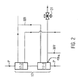
- the recooling unit 17 is preferably formed at least two stages to connect the heat exchange line 25 with the input side first stage 17-1 and thus ensure in this the highest possible temperature level. As a result, the most effective heat transfer from the recooling unit 17 to the heat exchange circuit 19 and into the buffer tank 7 is to be made possible. In the Fig. 2 only a second cooling stage 17-2 is indicated. For the method according to the invention, however, the number of subsequent cooling stages is insignificant insofar as only a suitable temperature level in the return 17a of the first stage 17-1 has to be provided.
- a further control device 31 is preferably provided in order to guide appropriately heated cooling water WR 'to the heat exchanger 24 with available waste heat in the recooling unit 17.
- the control device 31 leads cooling water WR 'returning from the recooling unit 17 to the cooling tower 30 in the Fig. 2 illustrated preferred embodiment of the recooling unit 17 is that the cooling water WR is brought to the highest possible and thus suitable for heating in the heat exchange circuit 19 temperature level and is available as additional, buffered by the buffer tank 7 heat source for preheating the product P available.
- the device according to the invention can be used as follows:
- the product P to be thermally treated and to be filled is continuously supplied to the preheating unit 3 and brought therefrom to a suitable temperature for subsequent short-term heating.
- the preheated product is heated in the heater 11 to the desired treatment temperature TP and held in the subsequent hot holding unit 13 for a predetermined treatment time at the desired treatment temperature TP.
- the duration of treatment is determined essentially by the flow rate of the product P and the length of the flow-through pipe section of the hot holding unit 13.
- the short-time heating by means of the heater 11 and the hot holding unit 13 can thus be carried out in a known manner.
- the thus treated product P ' is supplied to the correction cooling unit 5. In this, the product is cooled to the desired filling temperature TP '.
- the preheating, heating, keeping hot and cooling to the filling temperature TP ' is carried out in a continuous product stream, so that the amounts of heat for the preheating, heating and waste heat amount during correction cooling during operation are substantially constant.
- the regulation takes place essentially as a function of the product temperature TP 'measured after the correction cooling before the filling. That is, the amounts of heat exchanged during the heat exchange for the heating and cooling are adjusted depending on the treatment temperature TP, the treatment time and the filling temperature TP '.
- the heat exchange in the hot water circuit 9 is stabilized for a continuous product flow and for this purpose not required returning cooling water HW 'fed into the heat exchange circuit 19.
- waste heat may be produced in the container cooling unit 15.
- the short-time heating system is started up, no filled containers are still cooled, so that initially no waste heat for introduction into the hot-water circuit 9 can be made available in the container-cooling unit 15.
- waste heat may still be generated in the container cooling unit 15, while the entire product charge has already been heat-treated, so that no preheating in the preheating unit 3 is required at this time. In both cases allows the buffer tank 7 a time equalization of the amount of heat provided in the hot water circuit 9 of the preheating unit. 3
- the product P 'at a standstill of the filling unit 22 can be cooled by means of the recooling unit 17 to a predetermined temperature level and thus driven in the circuit.
- waste heat accumulates at the recooling unit 17 which, according to the invention, can be fed into the buffer tank 7 and thus into the hot water circuit 9.
- the buffer tank 7 allows a flexible connection of different waste heat sources to the hot water circuit 9 of the short-time heating system 1. It can thus also waste heat sources from other production areas are involved.
Description
Die Erfindung betrifft ein Verfahren und eine Vorrichtung zum Erhitzen eines flüssigen Produkts vor dessen Abfüllung.The invention relates to a method and apparatus for heating a liquid product prior to its filling.
Flüssige Produkte, wie beispielsweise Säfte und dergleichen, werden üblicherweise durch Wärmebehandlung haltbar gemacht und vorzugsweise heiß in Behälter abgefüllt. Die Wärmebehandlung ist beispielsweise eine Pasteurisierung in einer Kurzzeiterhitzungsanlage. Derartige Anlagen umfassen in der Regel einen Erhitzer zum Durchführen der Wärmebehandlung sowie eine Vorwärmeinheit, um das Produkt vor der Wärmebehandlung auf eine geeignete Eingangstemperatur vorzuwärmen, und einen Korrekturkühler, um die Produkttemperatur nach der Wärmebehandlung auf eine geeignete Abfülltemperatur abzukühlen.Liquid products, such as juices and the like, are usually preserved by heat treatment and preferably filled into containers in hot condition. The heat treatment is, for example, pasteurization in a short-time heating plant. Such equipment typically includes a heater for carrying out the heat treatment and a preheating unit for preheating the product to a suitable inlet temperature prior to the heat treatment, and a correction cooler for cooling the product temperature to a suitable filling temperature after the heat treatment.
Hierzu ist es beispielsweise aus der
Aus der
In Kurzzeiterhitzungsanlagen können die entsprechenden Wärmemengen je nach Betriebszustand der Wärmebehandlungsanlage in den einzelnen Anlagenteilen in stark unterschiedlichen Mengen anfallen, beispielsweise beim Hochfahren, Herunterfahren, bei Abfüllunterbrechungen und dergleichen.In short-term heating systems, depending on the operating state of the heat treatment plant, the corresponding amounts of heat can be produced in very different amounts in the individual plant components, for example during start-up, shut-down, filling interruptions and the like.
Für eine Produkt schonende Wärmebehandlung ist es insbesondere wünschenswert, dass die Behandlungstemperaturen in den einzelnen Behandlungsstufen möglichst gleichmäßig sind und dass das Produkt bei einem möglichst geringen Überdruck behandelt werden kann. Dieses Ziel lässt sich bei den bekannten Wärmebehandlungsanlagen mit Wärmerückgewinnung jedoch nur unzureichend realisieren.For a gentle product heat treatment, it is particularly desirable that the treatment temperatures in the individual treatment stages are as uniform as possible and that the product can be treated at the lowest possible pressure. However, this goal can only be achieved inadequately in the known heat treatment systems with heat recovery.
Es besteht somit der Bedarf für in dieser Hinsicht verbesserte Verfahren zur regenerativen Kurzeiterhitzung fließender Produkte und für entsprechend optimierte Behandlungsanlagen.There is thus a need for processes improved in this regard for the regenerative cure time heating of flowing products and for correspondingly optimized treatment plants.
Die gestellte Aufgabe wird gelöst mit einem Verfahren nach Anspruch 1 mit den folgenden Schritten: a) Vorwärmen des Produkts für das Kurzzeiterhitzen; b) Korrekturkühlen des kurzzeiterhitzten Produkts, insbesondere für dessen anschließendes Heißabfüllen; und c) Zwischenspeichern von im Schritt b) erwärmtem Kühlwasser zur Verwendung als Heizwasser für den Schritt a), wobei dem zwischengespeicherten Kühlwasser beim Kühlen abgefüllten Produkts und/oder beim Rückkühlen nicht abgefüllten Produkts gewonnene Abwärme zugeführt wird.The object is achieved by a method according to
Durch das Zwischenspeichern lässt sich beim Kühlen des behandelten Produkts gewonnene Wärmeenergie auch bei wechselnden Betriebszuständen, insbesondere bei einem Anfahren oder Herunterfahren der Behandlungsanlage, zum Vorwärmen des Produkts einsetzen. Dadurch, dass dem zwischengespeicherten Kühlwasser in unterschiedlichen Abschnitten der Wärmebehandlungsanlage anfallende Abwärme zugeführt wird, lässt sich bei unterschiedlichen Betriebszuständen anfallende Abwärme sammeln und zeitlich mitteln. Das erfindungsgemäße Verfahren eignet sich deshalb besonders zum schonenden Kurzzeiterhitzen unterschiedlicher flüssiger Produkte, beispielsweise zur Pasteurisierung von Getränken. Außerdem lässt sich die für das Vorwärmen des Produkts insgesamt zur Verfügung stehende zurück gewonnene Wärmemenge erhöhen und sich somit der Energieverbrauch optimieren.By caching, thermal energy obtained during cooling of the treated product can also be used to preheat the product under changing operating conditions, in particular when starting up or shutting down the treatment plant. The fact that the cached cooling water is supplied in different sections of the heat treatment plant waste heat accumulating at different operating conditions accumulating waste heat and averaged over time. The inventive method is therefore particularly suitable for gentle short-term heating of different liquid products, for example for the pasteurization of beverages. In addition, the total amount of heat recovered for preheating the product can be increased, thus optimizing energy consumption.
Vorzugsweise wird die Abwärme in Form von Wärmeaustauschwasser zugeführt, um dieses gemeinsam mit dem erwärmten Kühlwasser als Heizwasser zwischenzuspeichern. Diese Form der Wärmerückgewinnung und Zwischenspeicherung ist besonders einfach zu realisieren, da beim Zwischenspeichern zwei Wasserkreisläufe zusammengeführt werden können. Zurückgewonnene Abwärmemengen könnten aber auch über Wärmetauscher zwischen dem Heizwasser und dem Wärmeaustauschwasser übertragen werden.Preferably, the waste heat is supplied in the form of heat exchange water to temporarily store this together with the heated cooling water as heating water. This form of heat recovery and caching is particularly easy to implement because when caching two water circuits can be merged. Recovered amounts of waste heat could also be transferred via heat exchangers between the heating water and the heat exchange water.
Bei einer besonders günstigen Ausgestaltung wird Wärme aus beim Rückkühlen erwärmtem Kühlwasser an das Wärmeaustauschwasser übertragen. Das Kühlwasser ist somit wärmer als das Wärmeaustauschwasser. Dadurch lässt sich die zur Verfügung stehende Abwärme für das Erwärmen des Heizwassers weiter steigern.In a particularly advantageous embodiment, heat is transferred from the cooling water heated during cooling to the heat exchange water. The cooling water is thus warmer than the heat exchange water. As a result, the available waste heat for heating the heating water can be further increased.
Vorzugsweise werden die Temperaturen des vom Rückkühlen zurück laufenden Kühlwassers und des Wärmeaustauschwassers gemessen. Dadurch lasen sich die Temperaturen vergleichen und feststellen, ob ein geeigneter Temperaturübergang möglich ist.Preferably, the temperatures of the cooling water returning from the recooling and the heat exchange water are measured. This allows the temperatures to be compared and to determine whether a suitable temperature transition is possible.
Vorzugsweise wird die Wärmeübertragung nur zugelassen, wenn das vom Rückkühlen zurück laufenden Kühlwassers wenigstens 2°C, insbesondere wenigstens 5°C, wärmer ist als das das Wärmeaustauschwasser. Dieser Temperaturunterschied ermöglicht eine besonders effiziente Wärmerückgewinnung und vermeidet insbesondere ein unerwünschtes Abkühlen des Wärmeaustauschwassers. Besonders wirkungsvoll ist ein Temperaturunterschied von wenigstens 8°C. Grundsätzlich ist ein erfindungsgemäßer Betrieb des beschriebenen Systems möglich, sobald das Kühlwasser wärmer ist als das Wärmeaustauschwasser.Preferably, the heat transfer is permitted only if the cooling water flowing back from the cooling back at least 2 ° C, in particular at least 5 ° C, is warmer than that of the heat exchange water. This temperature difference allows a particularly efficient heat recovery and in particular avoids unwanted cooling of the heat exchange water. Particularly effective is a temperature difference of at least 8 ° C. In principle, an inventive operation of the described system is possible as soon as the cooling water is warmer than the heat exchange water.
Bei einer besonders günstigen Variante wird ferner vom Vorwärmen im Schritt a) zurück laufendes Heizwasser zum Korrekturkühlen verwendet. Das Heizwasser hat dann eine zum Korrekturkühlen geeignete Temperatur, so dass ein separater Kühlkreislauf zum Korrekturkühlen entbehrlich wird.In a particularly favorable variant, further heating water used for corrective cooling is also used by the preheating in step a). The heating water then has a suitable temperature for corrective cooling, so that a separate cooling circuit for corrective cooling is unnecessary.
Vorzugsweise wird die im Schritt b) korrigierte Produkttemperatur gemessen, und ein erster Anteil des vom Vorwärmen zurück laufenden Heizwassers wird in Abhängigkeit von der gemessenen Produkttemperatur als Kühlwasser im Schritt b) verwendet. Dies ist insbesondere vorteilhaft, da die erforderliche Kühlleistung in der Korrekturkühleinheit und die erforderliche Heizleistung in der Vorwärmeinheit bei laufender Wärmebehandlung näherungsweise konstant sind. Es lässt sich somit ein einfacher und stabiler Regelkreis bereitstellen.Preferably, the product temperature corrected in step b) is measured, and a first portion of the heating water returning from preheating is used as the cooling water in step b), depending on the measured product temperature. This is particularly advantageous because the required cooling capacity in the correction cooling unit and the required heating power in the preheating unit are approximately constant during ongoing heat treatment. It can thus provide a simple and stable control loop.
Ein restlicher Anteil des vom Vorwärmen zurück laufenden Heizwassers wird vorzugsweise als Wärmeaustauschwasser zum Zuführen der Abwärme im Schritt c) verwendet wird. Dadurch lässt sich ein Wärmeaustauschkreislauf auf einfache Weise realisieren.A remaining portion of the heating water flowing back from preheating is preferably used as the heat exchange water for supplying the waste heat in step c). As a result, a heat exchange cycle can be realized in a simple manner.
Die gestellte Aufgabe wird ferner mit einer Vorrichtung nach Anspruch 9 gelöst. Demnach umfasst diese: eine Vorwärmeinheit zum Vorwärmen des Produkts für das Erhitzen; eine Korrekturkühleinheit zum Abkühlen des kurzzeiterhitzten Produkts, insbesondere für ein anschließendes Heißabfüllen des Produkts; einen Puffertank zum Zwischenspeichern von in der Korrekturkühleinheit erwärmtem Kühlwasser; einen Heißwasserkreislauf zum Verbinden eines Ausgangs des Puffertanks mit dem Vorlauf der Vorwärmeinheit; und einen Wärmeaustauschkreislauf zum Zuführen von Abwärme aus einer Behälterkühleinheit und/oder einer Rückkühleinheit in den Puffertank.The stated object is further achieved with a device according to
Mit Hilfe des Puffertanks lässt sich beim Kühlen des behandelten Produkts gewonnene Wärmeenergie auch bei wechselnden Betriebszuständen, insbesondere bei einem Anfahren oder Herunterfahren der Behandlungsanlage, gleichmäßig in die Vorwärmeinheit einspeisen. Außerdem kann dem Puffertank in unterschiedlichen Abschnitten der Wärmebehandlungsanlage erwärmtes Wasser zugeführt werden. Damit lassen sich bei unterschiedlichen Betriebszuständen anfallende Wärmemengen sammeln und zeitlich mitteln. Die erfindungsgemäße Vorrichtung eignet sich deshalb besonders zum schonenden Kurzzeiterhitzen unterschiedlicher flüssiger Produkte bei reduziertem Überdruck, beispielsweise zur Pasteurisierung von Getränken.With the help of the buffer tank, heat energy obtained during cooling of the treated product can be fed evenly into the preheating unit even under changing operating conditions, in particular when starting up or shutting down the treatment plant. In addition, heated water can be supplied to the buffer tank in different sections of the heat treatment plant. This can be collected at different operating conditions accumulating amounts of heat and averaged over time. The device according to the invention is therefore particularly suitable for the gentle short-term heating of different liquid products at reduced overpressure, for example for the pasteurization of beverages.
Mit dem Wärmeaustauschkreislauf lässt sich die für das Vorwärmen des Produkts einsetzbare zurückgeführte Wärmemenge erhöhen. Die in der Behälterkühleinheit, beispielsweise einem Kühltunnel, je nach Betriebszustand unterschiedlich anfallende Wärmemenge, kann in dem Puffertank zwischengespeichert werden, so dass für das Vorwärmen eine zeitlich weitgehend konstante Wärmemenge zur Verfügung steht.The heat exchange cycle can increase the amount of heat that can be used to preheat the product. The amount of heat accumulating in the container cooling unit, for example a cooling tunnel, depending on the operating state, can be temporarily stored in the buffer tank, so that a quantity of heat which is largely constant over time is available for preheating.
Eine besonders günstige Ausführungsform umfasst ferner mit eine Regeleinrichtung im Rücklauf der Vorwärmeinheit, um diesen anteilig mit der Korrekturkühleinheit und dem Wärmeaustauschkreislauf zu verbinden. Mit Hilfe der Regeleinrichtung lässt sich der Kühlstrom im Vorlauf der Korrekturkühleinheit einstellen, um nach der Korrekturkühleinheit eine konstante Produkttemperatur zu erzielen. Ein zusätzlicher Anteil des von der Vorwärmeinheit rücklaufenden Wassers kann der Behälterkühleinheit zugeführt werden. Ein derartiger Regelkreis lässt sich insbesondere deshalb auf einfache Weise realisieren, da die an der Korrekturkühleinheit anfallende Abwärmemenge während der Behandlung einer Produktcharge zeitlich weitgehend konstant ist. Ebenso ist die für das Vorwärmen des Produkts benötigte Wärmemenge weitgehend unabhängig vom Betriebszustand der Behandlungsanlage näherungsweise konstant.A particularly favorable embodiment further comprises a control device in the return flow of the preheating unit in order to connect it proportionally with the correction cooling unit and the heat exchange circuit. With the help of the control device, the cooling flow in the flow of the correction cooling unit can be adjusted in order to achieve a constant product temperature after the correction cooling unit. An additional portion of the water returning from the preheating unit may be supplied to the container cooling unit. Such a control circuit can therefore be realized in a simple manner, in particular, since the waste heat quantity occurring at the correction cooling unit is substantially constant in time during the treatment of a product charge. Likewise, the amount of heat required for the preheating of the product is largely independent of the operating state of the treatment plant is approximately constant.
Vorzugsweise ist ferner eine Wärmeaustauschleitung vorgesehen, um Abwärme aus dem Rücklauf einer Rückkühleinheit an den Wärmeaustauschkreislauf zu übertragen, insbesondere mit Hilfe eines Wärmetauschers.Preferably, a heat exchange line is further provided to transfer waste heat from the return of a recooling unit to the heat exchange circuit, in particular by means of a heat exchanger.
Dadurch lässt sich die rückführbare Wärmemenge zusätzlich erhöhen. Somit lässt sich Wärme insbesondere bei einem Betriebszustand, in dem das Produkt nicht abgefüllt wird, zurückgewinnen. Dies ist insbesondere in Kombination mit einer Wärmerückgewinnung aus einer Behälterkühlanlage vorteilhaft, da dann sowohl in einem Betriebszustand, in dem das Produkt abgefüllt wird, als auch in einem Betriebszustand, in dem kein Produkt abgefüllt wird, Abwärme zur Rückgewinnung für das Vorwärmen zur Verfügung steht. Somit lässt sich Abwärme besonders gleichmäßig in den Puffertank einspeisen.As a result, the traceable amount of heat can be additionally increased. Thus, heat can be recovered especially in an operating condition in which the product is not bottled. This is particularly advantageous in combination with a heat recovery from a container cooling system, since then in an operating state in which the product is filled, as well as in an operating state in which no product is filled, waste heat for recovery for preheating is available. Thus, waste heat can be particularly evenly fed into the buffer tank.
Mit einem Wärmetauscher lässt sich die Wärme aus der Wärmeaustauschleitung auch in dem Fall einspeisen, in dem die Wärmeaustauschleitung selbst nicht Bestandteil des Heißwasserkreislaufs oder Wärmeaustauschkreislaufs sein kann, beispielsweise aus hygienischen Gründen. Der Wärmetauscher könnte alternativ auch an dem Puffertank vorgesehen sein, um die Wärme aus der Wärmeaustauschleitung direkt in diesen einzuspeisen.With a heat exchanger, the heat from the heat exchange line can also feed in the case in which the heat exchange line itself can not be part of the hot water cycle or heat exchange cycle, for example, for hygienic reasons. The heat exchanger could alternatively be provided on the buffer tank to feed the heat from the heat exchange line directly into this.
Vorzugsweise ist der Durchfluss durch die Wärmeaustauschleitung regelbar, insbesondere in Abhängigkeit von einem Temperaturunterschied zum Wärmeaustauschkreislauf. Eine Regeleinrichtung im Rücklauf der Rückkühleinheit ermöglicht hierbei ein dosiertes Einspeisen der Wärme, je nach Verfügbarkeit von Abwärme und Bedarf. Zu diesem Zweck kann eine Vergleichseinrichtung zum Vergleich der Wassertemperatur in der Wärmeaustauschleitung und im Wärmeaustauschkreis vorgesehen sein. Dadurch kann sichergestellt werden, dass eine Wärmeübertragung nur dann stattfindet, wenn die Wassertemperatur in der Wärmeaustauschleitung um ein vorgegebenes Maß über der Wassertemperatur des Wärmeaustauschkreises liegt. Insbesondere kann damit verhindert werden, dass das Wasser in dem Wärmeaustauschkreis durch die Wärmeaustauschleitung gekühlt wird.Preferably, the flow through the heat exchange line is controllable, in particular as a function of a temperature difference to the heat exchange cycle. A control device in the return of the recooling unit allows a metered feeding the heat, depending on the availability of waste heat and demand. For this purpose, a comparison device may be provided for comparing the water temperature in the heat exchange line and in the heat exchange circuit. This can ensure that a heat transfer takes place only when the water temperature in the heat exchange line is a predetermined amount above the water temperature of the heat exchange circuit. In particular, it can be prevented that the water is cooled in the heat exchange circuit through the heat exchange line.
Eine besonders günstige Ausführungsform umfasst eine wasserseitig wenigstens zweistufige Rückkühleinheit, um dem Puffertank Abwärme aus der heißesten, insbesondere ausschließlich aus der heißesten, Stufe der Rückkühleinheit zuzuführen. Dadurch lässt sich ein gewünschtes, möglichst hohes Temperaturniveau in der Wärmeaustauschleitung bereitstellen. Damit lässt sich insbesondere eine Wassertemperatur in der Wärmeaustauschleitung erzielen, die höher ist als die Wassertemperatur in dem Wärmeaustauschkreislauf.A particularly favorable embodiment comprises a water-side at least two-stage recooling unit to supply the buffer tank waste heat from the hottest, especially exclusively from the hottest, stage of the recooling unit. This can provide a desired, highest possible temperature level in the heat exchange line. In particular, a water temperature in the heat exchange line which is higher than the water temperature in the heat exchange cycle can thus be achieved.
Bei einer weiteren günstigen Ausführungsform der erfindungsgemäßen Vorrichtung ist ferner wenigstens eine weitere Wärmeaustauschleitung vorgesehen, um dem Puffertank Abwärme aus einer Einheit zum Reinigen von Behältern und/oder einem Sudhaus zuzuführen. Dadurch lässt sich der Anteil an zurückgeführter Abwärme für das Vorwärmen des Produkts weiter erhöhen. Durch das Anschließen weiterer Wärmequellen kann außerdem eine noch gleichmäßigere Wärmezufuhr in den Puffertank realisiert werden. Hierzu können in den jeweiligen Wärmeaustauschleitungen geeignete Regeleinrichtungen zum Regeln des Wärmestroms vorgesehen sein.In a further advantageous embodiment of the device according to the invention at least one further heat exchange line is further provided to supply the buffer tank waste heat from a unit for cleaning containers and / or a brewhouse. As a result, the proportion of recycled waste heat for preheating the product can be further increased. By connecting additional heat sources can also be realized even more even heat in the buffer tank. For this purpose, suitable control devices for regulating the heat flow can be provided in the respective heat exchange lines.
Vorzugsweise ist an dem Puffertank eine Reinigungsöffnung, beispielsweise ein Abwasserablauf, vorgesehen. Dadurch lässt sich der Puffertank, und mit ihm der angeschlossene Heißwasserkreislauf auf einfache Weise reinigen.Preferably, a cleaning opening, for example a waste water drain, is provided on the buffer tank. This makes it easy to clean the buffer tank, and with it the connected hot water circuit.
Eine bevorzugte Ausführungsform der Erfindung ist in der Zeichnung dargestellt. Es zeigen:
-
Fig. 1 ein schematisches Rohrleitungs- und Instrumentenfließbild einer bevorzugten Ausführungsform; und -
Fig. 2 einen Ausschnitt aus dem Fließbild derFig. 1 , bei einer Variante mit einer zweistufigen Rückkühleinheit.
-
Fig. 1 a schematic piping and instrument flow diagram of a preferred embodiment; and -
Fig. 2 a section of the flow chart ofFig. 1 , in a variant with a two-stage recooling unit.
Wie die
Es ist ferner ein Heißwasserkreislauf 9 vorgesehen, in dem das Heizwasser HW von einem Ausgang 7a des Puffertanks 7 zum Vorlauf 3a der Vorwärmeinheit 3 gefördert wird. Ein erster Anteil des aus dem Rücklauf 3b der Vorwärmeinheit 3 zurück fließenden abgekühlten Heizwassers HW' wird als Kühlwasser KW zum Vorlauf 5a der Korrekturkühleinheit 5 geleitet. Das beim Korrekturkühlen erwärmte Kühlwasser KW' fließt aus dem Rücklauf 5b der Korrekturkühleinheit 5 zu einem ersten Eingang 7b des Puffertanks 7, um dort als ein erster Anteil des Heizwassers HW zwischengespeichert zu werden.Furthermore, a
Zwischen der Vorwärmeinheit 3 und der Korrekturkühleinheit 5 ist produktseitig in bekannter Weise eine Behandlungseinheit 10 zum Kurzzeiterhitzen, beispielsweise zur Pasteurisierung, des Produkts P vorgesehen, beispielsweise umfassend einen Erhitzer 11 und eine Heißhalteeinheit 13. Die Vorwärmeinheit 3, der Erhitzer 11 und die Korrekturkühleinheit 5 werden beispielsweise durch Wärmetauscher bekannter Bauart ausgebildet. Die Heißhalteeinheit 13 umfasst beispielsweise eine Rohrstrecke oder ein Rohrsystem bekannter Bauart.Between the preheating
Das aus dem Puffertank 7 anströmende Heizwasser HW wird je nach Bedarf durch einen (nicht dargestellten) Wärmetauscher beispielsweise mittels Dampf zusätzlich erwärmt. Auch der Erhitzer 11 kann in bekannter Weise mit Dampf beheizt werden (nicht dargestellt).The inflowing out of the
Das Heizwasser HW und damit die Vorwärmeinheit 3 werden je nach Verfügbarkeit durch zurück gewonnene Abwärme aus der Korrekturkühleinheit 5 und vorzugsweise auch mit Abwärme zusätzlicher Kühleinheiten erwärmt. Diese können, wie in der
Zur Wärmerückgewinnung von der Behälterkühleinheit 15 ist ein Wärmeaustauschkreislauf 19 vorgesehen, der von dem Heißwasserkreislauf 9 an einer Regeleinrichtung 20, beispielsweise einer verstellbaren Klappe, zum Aufteilen des in der Vorwärmeinheit 3 abgekühlten Heizwassers HW' abzweigt. Von dort führt der Wärmeaustauschkreislauf 19 einen zweiten Anteil des zurücklaufenden Heizwassers HW' als Wärmeaustauschwasser WA zu einem Wärmetauscher 21 im Bereich der Behälterkühleinheit 15 und weiter zu einem zweiten Eingang 7c des Puffertanks 7. Mit Hilfe des Wärmetauschers 21 kann somit beim Abkühlen abgefüllter Behälter gewonnene Abwärme an den Wärmeaustauschkreislauf 19 übertragen und das auf diese Weise erwärmte Wärmeaustauschwasser WA' anschließend in dem Puffertank 7 zwischengespeichert werden.For heat recovery from the
Während die an der Behälterkühleinheit 15 zur Verfügung stehende Abwärme vom Betriebszustand einer lediglich schematisch angedeuteten Fülleinheit 22 zum Abfüllen des Produkts P' in Behälter abhängig ist, steht an der Korrekturkühleinheit 5 im laufenden Betrieb eine im Wesentlichen zeitlich konstante Abwärmemenge zur Verfügung, die dem Puffertank 7 kontinuierlich mit dem erwärmten Kühlwasser KW' zugeführt werden kann. Somit lässt sich mit Hilfe des Puffertanks 7 Abwärme aus unterschiedlichen Kühleinheiten sammeln und zeitlich mitteln, um auch bei unregelmäßigen oder schwankenden Betriebszuständen einzelner Behandlungseinheiten einen geeigneten zurückgeführten Wärmestrom im Vorlauf 3a der Vorwärmeinheit 3 bereit zu stellen.While the waste heat available at the
In Abhängigkeit von der hinter der Korrekturkühleinheit 5 mittels einer Temperaturmesseinrichtung 23 gemessenen Produkttemperatur TP' stellt die Regeleinrichtung 20 einen ersten Anteil des aus der Vorwärmeinheit 3 zurückfließenden Wassers HW' als Kühlwasser KW für die Korrekturkühleinheit 5 zur Verfügung. Der nicht für die Korrekturkühlung eingesetzte verbleibende Anteil des aus der Vorwärmeinheit 3 zurückfließenden Wassers HW' wird in den Wärmeaustauschkreislauf 19 als Wärmeaustauschwasser WA eingespeist. Somit lassen sich die für das Vorwärmen benötigten Wärmemengen und die beim Korrekturkühlen abzuführenden Wärmemengen unter Einbeziehung des Puffertanks 7 an einen kontinuierlichen Strom des zu behandelnden Produkts P exakt anpassen und gleichzeitig überschüssige und/oder wechselnde Wärmemengen aus wärmebehandeltem Produkt zurückgewinnen und zu einem geeigneten Zeitpunkt für die Wärmebehandlung nachfließenden Produkts nutzen. Durch die Zwischenspeicherung im Puffertank 7 wird eine besonders gleichmäßige und Produkt schonende Kurzzeiterhitzung bei geringem Energieeinsatz und geringem Überdruck ermöglicht.Depending on the product temperature TP 'measured behind the
Wie die
In dem Wärmeaustauschkreislauf 19 und der Wärmeaustauschleitung 25 sind jeweils vor dem Wärmetauscher 24 Temperaturmesseinrichtungen 27, 28 vorgesehen, um die Wassertemperatur im Wärmeaustauschkreislauf 19 und in der Wärmeaustauschleitung 25 zu messen und zu vergleichen. Dadurch wird sichergestellt, dass ein Wärmeaustausch in dem Wärmeaustauscher 24 nur dann erfolgt, wenn die Wassertemperatur in der Wärmeaustauschleitung 25 um einen vorgegebenen Betrag höher liegt als die Temperatur in dem Wärmeaustauschkreislauf 19. Ein geeigneter Temperaturunterschied ist beispielsweise wenigstens 5°C oder insbesondere wenigstens 10°C.In the
Anders gesagt, erfolgt ein Wärmeaustausch in dem Wärmetauscher 24 nur dann, wenn an der Rückkühleinheit 17 eine geeignete Abwärmemenge zur Verfügung steht. Im Gegensatz zur Korrekturkühleinheit 5 fällt die Abwärme an der Rückkühleinheit 17 im laufenden Betrieb in der Regel diskontinuierlich an. Jedoch ermöglicht auch hier die Zwischenspeicherung im Puffertank 7 eine effiziente Nutzung der nur zeitweise anfallenden Abwärme aus der Rückkühleinheit 17. Somit ermöglicht der Puffertank 7 generell die Kombination kontinuierlich anfallender Abwärmemengen, wie beispielsweise aus der Korrekturkühleinheit 5, mit unter Umständen unregelmäßig anfallenden Abwärmemengen, wie beispielsweise aus erwärmtem Kühlwasser WR' der Rückkühleinheit 17 und/oder der Behälterkühleinheit 15.In other words, a heat exchange takes place in the
Der Vollständigkeit halber sind in der
Ebenso ist eine Reinigungsöffnung 7d des Pufferbehälters 7 angedeutet, durch den eine Reinigung des Pufferbehälters 7 und der daran angeschlossenen Wasserkreisläufe ermöglicht wird.Likewise, a
Wie die
Im Rücklauf 17a der Rückkühleinheit 17 ist vorzugsweise eine weitere Regeleinrichtung 31 vorgesehen, um bei verfügbarer Abwärme in der Rückkühleinheit 17 geeignet erwärmtes Kühlwasser WR' zum Wärmetauscher 24 zu leiten. Alternativ leitet die Regeleinrichtung 31 aus der Rückkühleinheit 17 zurücklaufendes Kühlwasser WR' zum Kühlturm 30. Entscheidend bei der in der
Mit der erfindungsgemäßen Vorrichtung kann wie folgt gearbeitet werden:The device according to the invention can be used as follows:
Das thermisch zu behandelnde und abzufüllende Produkt P wird kontinuierlich der Vorwärmeinheit 3 zugeführt und von dieser auf eine geeignete Temperatur zum nachfolgenden Kurzzeiterhitzen gebracht. Das vorgewärmte Produkt wird in dem Erhitzer 11 auf die gewünschte Behandlungstemperatur TP erhitzt und in der anschließenden Heißhalteeinheit 13 für eine vorgegebene Behandlungszeit auf der gewünschten Behandlungstemperatur TP gehalten. Die Behandlungsdauer wird hierbei im Wesentlichen durch die Strömungsgeschwindigkeit des Produkts P und die Länge der durchströmten Rohrstrecke der Heißhalteeinheit 13 bestimmt. Die Kurzzeiterhitzung mit Hilfe des Erhitzers 11 und der Heißhalteeinheit 13 kann somit in bekannter Weise erfolgen. Das derart behandelte Produkt P' wird der Korrekturkühleinheit 5 zugeführt. In dieser wird das Produkt auf die gewünschte Abfülltemperatur TP' abgekühlt.The product P to be thermally treated and to be filled is continuously supplied to the
Hierbei erfolgt das Vorwärmen, Erhitzen, Heißhalten und Abkühlen auf die Abfülltemperatur TP' in einem kontinuierlichen Produktstrom, so dass die Wärmemengen für das Vorwärmen, das Erhitzen und die Abwärmemenge beim Korrekturkühlen im laufenden Betrieb im Wesentlichen gleichbleibend sind. Die Regelung erfolgt hierbei im Wesentlichen in Abhängigkeit von der nach der Korrekturkühlung gemessenen Produkttemperatur TP' vor dem Abfüllen. Das heißt, die beim Wärmeaustausch für das Erwärmen und Abkühlen jeweils ausgetauschten Wärmemengen werden in Abhängigkeit von der Behandlungstemperatur TP, der Behandlungsdauer und der Abfülltemperatur TP' eingestellt. Mit Hilfe der Regeleinrichtung 20 wird der Wärmeaustausch im Heißwasserkreislauf 9 für einen kontinuierlichen Produktstrom stabilisiert und zu diesem Zweck nicht benötigtes zurücklaufendes Kühlwasser HW' in den Wärmeaustauschkreislauf 19 eingespeist.Here, the preheating, heating, keeping hot and cooling to the filling temperature TP 'is carried out in a continuous product stream, so that the amounts of heat for the preheating, heating and waste heat amount during correction cooling during operation are substantially constant. In this case, the regulation takes place essentially as a function of the product temperature TP 'measured after the correction cooling before the filling. That is, the amounts of heat exchanged during the heat exchange for the heating and cooling are adjusted depending on the treatment temperature TP, the treatment time and the filling temperature TP '. With the help of the
Je nach Betriebszustand können unterschiedliche Abwärmemengen in der Behälterkühleinheit 15 anfallen. Beispielsweise werden beim Hochfahren der Kurzzeiterhitzungsanlage noch keine befüllten Behälter gekühlt, so dass in der Behälterkühleinheit 15 zunächst keine Abwärme zum Einleiten in den Heißwasserkreislauf 9 zur Verfügung gestellt werden kann. Ebenso kann beim Herunterfahren der Behandlungsanlage noch Abwärme in der Behälterkühleinheit 15 anfallen, während bereits die gesamte Produktcharge wärmebehandelt wurde, so dass zu diesem Zeitpunkt keine Vorwärmung in der Vorwärmeinheit 3 mehr benötigt wird. In beiden Fällen ermöglicht der Puffertank 7 einen zeitlichen Ausgleich der zur Verfügung gestellten Wärmemenge in dem Heißwasserkreislauf 9 der Vorwärmeinheit 3.Depending on the operating state, different amounts of waste heat may be produced in the
Ebenso kann das Produkt P' bei einem Stillstand der Fülleinheit 22 mit Hilfe der Rückkühleinheit 17 auf ein vorgegebenes Temperaturniveau abgekühlt und somit im Kreislauf gefahren werden. In diesem Fall fällt an der Rückkühleinheit 17 Abwärme an, die erfindungsgemäß in den Puffertank 7 und somit in den Heißwasserkreislauf 9 eingespeist werden kann. Somit lässt sich auch bei einer nur kurzeitigen Verfügbarkeit von Abwärme in der Rückkühleinheit 17 im Wesentlichen unabhängig von dem Betriebszustand Abwärme zurückgewinnen und für das Vorwärmen nachströmenden Produkts P nutzen.Likewise, the product P 'at a standstill of the filling
An dem gezeigten Heißwasserkreislauf 9 könnten mit Hilfe geeigneter Wärmetauscher und Zuleitungen weitere Abwärmequellen mittels des Puffertanks 7 angeschlossen werden. Dem Heizwasser HW kann zusätzlich Abwärme aus anderen Anlagenbereichen zugeführt und zwischengespeichert werden, beispielsweise aus einem Sudhaus und/oder einer Reinigungsanlage für Behälter. Somit ermöglicht insbesondere der Puffertank 7 eine flexible Anbindung unterschiedlicher Abwärmequellen an den Heißwasserkreislauf 9 der Kurzzeiterhitzungsanlage 1. Es können somit auch Abwärmequellen aus anderen Produktionsbereichen eingebunden werden.At the
Es wäre auch denkbar, getrennte Puffertanks für einzelne Abwärmequellen vorzusehen und das Heizwasser HW außerhalb des Puffertanks 7 zu mischen. Ebenso könnten zusätzliche Wärmetauscher vorgesehen sein, um beispielsweise den Heißwasserkreislauf von Wärmeaustauschkreisläufen zu trennen, solange eine Erwärmung des Heizwassers HW für die Produktvorwärmung aus unterschiedlichen Abwärmequellen möglich ist. Die gezeigte Ausführungsform ist jedoch besonders einfach und zuverlässig zu realisieren.It would also be conceivable to provide separate buffer tanks for individual waste heat sources and to mix the heating water HW outside of the
Claims (15)
- Method of flash pasteurizing a liquid product (P) before it is filled, comprising the steps of:a) preheating the product (P) for flash pasteurization;b) correction cooling the flash pasteurized product (P'), in particular for subsequently hot-filling the same; andc) intermediately storing cooling water (KW') heated in step b) to be used as heating water (HW) for step a), wherein waste heat obtained during the cooling of filled-in product (P") and/or recooling of not filled-in product (P') is supplied to the intermediately stored cooling water (KW').
- Method according to claim 1, wherein the waste heat is supplied in the form of heat transfer water (WA', WA") to intermediately store the latter together with the heated cooling water (KW') a heating water (HW).
- Method according to claim 2, wherein heat from recooling heated cooling water (WR') is transferred to the heat transfer water (WA').
- Method according to claim 3, wherein the temperatures of the cooling water (WR') flowing back from recooling and of the heat transfer water (WA') are measured.
- Method according to claim 4, wherein the heat transfer to the heat transfer water (WA') is only permitted if the cooling water (WR') flowing back from recooling is warmer than the heat transfer water (WA') by at least 2 °C, in particular at least 5 °C.
- Method according to at least one of the preceding claims, wherein furthermore heating water (HW') flowing back from preheating in step a) is used for correction cooling.
- Method according to claim 6, wherein the product temperature (TP") corrected in step b) is measured, and a first proportion of the heating water (HW') flowing back from preheating is used as cooling water (KW) in step b) depending on the measured product temperature (TP').
- Method according to claim 7, wherein a remaining proportion of the heating water (HW') flowing back from preheating is used as heat transfer water (WA) for supplying the waste heat in step c).
- Device for flash pasteurizing a liquid product before it is filled, having:- a preheating unit (3) for preheating the product (P) for heating;- a correction cooling unit (5) for cooling the flash pasteurized product (P'), in particular for subsequently hot filling the product;- a buffer tank (7) for intermediately storing cooling water heated in the correction cooling unit;- a hot water cycle (9) for connecting an outlet (7a) of the buffer tank with the flow line (3a) of the preheating unit; and- a heat transfer cycle (19) for supplying waste heat from a container cooling unit (15) and/or a recooling unit (17) into the buffer tank.
- Device according to claim 9, further having a controlling device (20) in the return line (3b) of the preheating unit (3) to connect it partially with the correction cooling unit (5) and the heat transfer cycle (19).
- Device according to claim 9 or 10, further having a heat transfer line (25) to transfer waste heat from the return line (17a) of a recooling unit (17) to the heat transfer cycle (19), in particular with the aid of a heat exchanger (24).
- Device according to claim 11, wherein the flow through the heat transfer line (25) is controllable, in particular depending on a temperature difference to the heat transfer cycle (19).
- Device according to at least one of claims 9 to 12, further having a recooling unit (17) with at least two stages on the water side for supplying the buffer tank with waste heat from the hottest, in particular exclusively from the hottest stage (17-1) of the recooling unit.
- Device according to at least one of claims 9 to 13, further having at least one further heat transfer line for supplying the buffer tank (7) with waste heat from a unit for cleaning containers and/or a brewhouse.
- Device according to at least one of claims 9 to 14, wherein a cleaning port (7d) is provided at the buffer tank (7).
Priority Applications (1)
| Application Number | Priority Date | Filing Date | Title |
|---|---|---|---|
| PL12177864T PL2567935T3 (en) | 2011-09-07 | 2012-07-25 | Device and method for heating a liquid product |
Applications Claiming Priority (1)
| Application Number | Priority Date | Filing Date | Title |
|---|---|---|---|
| DE102011082286A DE102011082286A1 (en) | 2011-09-07 | 2011-09-07 | Method and apparatus for heating a liquid product |
Publications (2)
| Publication Number | Publication Date |
|---|---|
| EP2567935A1 EP2567935A1 (en) | 2013-03-13 |
| EP2567935B1 true EP2567935B1 (en) | 2014-06-04 |
Family
ID=46583881
Family Applications (1)
| Application Number | Title | Priority Date | Filing Date |
|---|---|---|---|
| EP12177864.1A Active EP2567935B1 (en) | 2011-09-07 | 2012-07-25 | Device and method for heating a liquid product |
Country Status (8)
| Country | Link |
|---|---|
| US (1) | US10039295B2 (en) |
| EP (1) | EP2567935B1 (en) |
| CN (1) | CN103040071B (en) |
| BR (1) | BR102012022447A2 (en) |
| DE (1) | DE102011082286A1 (en) |
| DK (1) | DK2567935T3 (en) |
| ES (1) | ES2474128T3 (en) |
| PL (1) | PL2567935T3 (en) |
Families Citing this family (9)
| Publication number | Priority date | Publication date | Assignee | Title |
|---|---|---|---|---|
| DE102013113335A1 (en) * | 2013-12-02 | 2015-06-03 | Krones Ag | Blow molding machine with heatable coolant supply |
| DE102016217342A1 (en) | 2016-09-12 | 2018-03-15 | Krones Ag | Filling plant for heat treatment and filling of a liquid |
| KR101785466B1 (en) * | 2017-02-28 | 2017-10-13 | 주식회사 성원데어리 | Manufacturing Method of Yoghurt |
| JP6521396B2 (en) * | 2017-07-04 | 2019-05-29 | 大日本印刷株式会社 | Aseptic filling system |
| DE102017215436A1 (en) * | 2017-09-04 | 2019-03-07 | Krones Ag | Apparatus and method for pasteurization and filling of medium |
| CN108606228A (en) * | 2018-05-04 | 2018-10-02 | 深圳市深晖企业有限公司 | A kind of beverage production process |
| DE102019126946A1 (en) * | 2019-10-08 | 2021-04-08 | Krones Aktiengesellschaft | Method and device for hot filling of liquid product |
| DE102020127542A1 (en) | 2020-10-20 | 2022-04-21 | Krones Aktiengesellschaft | Filling installation and process for hot filling a liquid product into containers |
| DE102022122825A1 (en) | 2022-09-08 | 2024-03-14 | Steinecker GmbH | Energy-efficient production of plant-based food products |
Family Cites Families (13)
| Publication number | Priority date | Publication date | Assignee | Title |
|---|---|---|---|---|
| US3622357A (en) * | 1970-07-20 | 1971-11-23 | Basf Wyandotte Corp | Automatic feed system for treating brewery pasteurizer water |
| US4263254A (en) * | 1979-08-01 | 1981-04-21 | Barry-Wehmiller Company | Apparatus for and method of conserving energy in pasteurizers |
| US4416194A (en) * | 1981-12-03 | 1983-11-22 | Fmc Corporation | Beverage pasteurizing system |
| US4441406A (en) * | 1982-06-14 | 1984-04-10 | Miller Brewing Company | Pasteurization apparatus |
| US4490401A (en) * | 1982-06-14 | 1984-12-25 | Miller Brewing Company | Pasteurization method |
| FR2589332B1 (en) | 1985-11-05 | 1989-12-01 | Baele Gangloff Ste Nouvelle | METHOD AND DEVICE FOR PASTEURIZING FOOD PRODUCTS CONTAINED IN CONTAINERS |
| US5503064A (en) | 1994-08-31 | 1996-04-02 | Custom Control Products, Inc. | Apparatus and method for controlling a pasteurizing system |
| AT1418U1 (en) * | 1996-06-24 | 1997-05-26 | Fischer Harald Dr | METHOD AND DEVICE FOR TEMPORARY HEATING, IN PARTICULAR PASTEURIZING, OF A FLOWABLE FOOD PRODUCT |
| DE29710507U1 (en) | 1996-06-24 | 1997-08-07 | Fischer Harald Dr | Device for the temporary heating, in particular pasteurization, of a flowable food product |
| US6214400B1 (en) | 1999-10-14 | 2001-04-10 | Lyco Manufacturing Inc. | Method for processing food product |
| DE10351689A1 (en) | 2003-11-06 | 2005-06-16 | Khs Maschinen- Und Anlagenbau Ag | Method for operating a pasteurization plant |
| DE102008031368A1 (en) | 2008-07-04 | 2010-01-07 | Khs Ag | Method and device for pasteurizing a liquid product |
| DE102008056597A1 (en) | 2008-11-10 | 2010-05-12 | Krones Ag | Hot filling plant with heat recovery |
-
2011
- 2011-09-07 DE DE102011082286A patent/DE102011082286A1/en not_active Withdrawn
-
2012
- 2012-07-25 ES ES12177864.1T patent/ES2474128T3/en active Active
- 2012-07-25 EP EP12177864.1A patent/EP2567935B1/en active Active
- 2012-07-25 DK DK12177864.1T patent/DK2567935T3/en active
- 2012-07-25 PL PL12177864T patent/PL2567935T3/en unknown
- 2012-09-05 BR BR102012022447A patent/BR102012022447A2/en not_active Application Discontinuation
- 2012-09-06 US US13/604,873 patent/US10039295B2/en not_active Expired - Fee Related
- 2012-09-07 CN CN201210328064.5A patent/CN103040071B/en not_active Expired - Fee Related
Also Published As
| Publication number | Publication date |
|---|---|
| DK2567935T3 (en) | 2014-06-30 |
| PL2567935T3 (en) | 2014-11-28 |
| DE102011082286A1 (en) | 2013-03-07 |
| US20130059055A1 (en) | 2013-03-07 |
| BR102012022447A2 (en) | 2016-05-24 |
| CN103040071B (en) | 2015-03-04 |
| US10039295B2 (en) | 2018-08-07 |
| EP2567935A1 (en) | 2013-03-13 |
| CN103040071A (en) | 2013-04-17 |
| ES2474128T3 (en) | 2014-07-08 |
Similar Documents
| Publication | Publication Date | Title |
|---|---|---|
| EP2567935B1 (en) | Device and method for heating a liquid product | |
| EP3355717B1 (en) | System and method for pasteurizing foods | |
| EP2532247B1 (en) | Product pre-warming with heat pump | |
| EP3068237B1 (en) | Method and system for pasteurization of products in containers | |
| EP2184257B1 (en) | Hot filling assembly with heat recovery | |
| EP3509980B1 (en) | Plant for heat treatment and filling uf liquids | |
| EP4068984B1 (en) | Plant for pasteurizing foodstuffs or beverages filled into closed containers by way of a process liquid | |
| EP3057442B1 (en) | Method and device for preheating a pumpable food product in hot filling with a heat pump | |
| EP2281467B1 (en) | Method and device for heating, in particular highly viscous products | |
| EP3831456A1 (en) | Device for making and providing sterile water and method for operating the device | |
| EP3988498A1 (en) | Filling system and method for filling a hot liquid product into containers | |
| EP2679919A2 (en) | Method for providing cold and hot water in a water supply system and drinking water device | |
| EP3166420B1 (en) | Thermal treatment device and a thermal treatment method | |
| DE102005030924A1 (en) | Pasteurization of fruit juices comprises an operating phase and stand by phase in which the food is passed across a flow path in a closed cycle circulating medium within the range of pasteurization stretch | |
| EP1610618B1 (en) | Device for dispensing liquid foodstuffs | |
| EP4335298A1 (en) | Method and apparatus for direct heating of liquid food products | |
| DE102008038351A1 (en) | Power station, has heat exchanger to which heat is delivered from fluid medium flowing from motor to feed pump at certain temperature, where heat exchanger returns heat to fluid medium flowing from feed pump to boiler | |
| DE102019126946A1 (en) | Method and device for hot filling of liquid product | |
| EP0671129B1 (en) | Process and apparatus for treatment of products in the food industry | |
| DE102011118660B4 (en) | A method and arrangement for the discontinuous supply of tempered water for use in a process for producing and / or treating a foodstuff | |
| DE102020207908A1 (en) | Device for PEF treatment of liquid media and processes | |
| AT1418U1 (en) | METHOD AND DEVICE FOR TEMPORARY HEATING, IN PARTICULAR PASTEURIZING, OF A FLOWABLE FOOD PRODUCT | |
| EP3269460A1 (en) | Bottle cleaning device and method for a process water circuit using the bottle cleaning device | |
| WO2016128256A1 (en) | Method for controlling a treatment system, in particular a treatment system for heating products, and treatment system |
Legal Events
| Date | Code | Title | Description |
|---|---|---|---|
| PUAI | Public reference made under article 153(3) epc to a published international application that has entered the european phase |
Free format text: ORIGINAL CODE: 0009012 |
|
| AK | Designated contracting states |
Kind code of ref document: A1 Designated state(s): AL AT BE BG CH CY CZ DE DK EE ES FI FR GB GR HR HU IE IS IT LI LT LU LV MC MK MT NL NO PL PT RO RS SE SI SK SM TR |
|
| AX | Request for extension of the european patent |
Extension state: BA ME |
|
| 17P | Request for examination filed |
Effective date: 20130821 |
|
| RBV | Designated contracting states (corrected) |
Designated state(s): AL AT BE BG CH CY CZ DE DK EE ES FI FR GB GR HR HU IE IS IT LI LT LU LV MC MK MT NL NO PL PT RO RS SE SI SK SM TR |
|
| RIC1 | Information provided on ipc code assigned before grant |
Ipc: B67C 3/04 20060101AFI20131029BHEP Ipc: A23C 3/03 20060101ALI20131029BHEP Ipc: A23L 2/46 20060101ALI20131029BHEP |
|
| GRAP | Despatch of communication of intention to grant a patent |
Free format text: ORIGINAL CODE: EPIDOSNIGR1 |
|
| INTG | Intention to grant announced |
Effective date: 20131218 |
|
| GRAS | Grant fee paid |
Free format text: ORIGINAL CODE: EPIDOSNIGR3 |
|
| GRAA | (expected) grant |
Free format text: ORIGINAL CODE: 0009210 |
|
| AK | Designated contracting states |
Kind code of ref document: B1 Designated state(s): AL AT BE BG CH CY CZ DE DK EE ES FI FR GB GR HR HU IE IS IT LI LT LU LV MC MK MT NL NO PL PT RO RS SE SI SK SM TR |
|
| REG | Reference to a national code |
Ref country code: GB Ref legal event code: FG4D Free format text: NOT ENGLISH |
|
| REG | Reference to a national code |
Ref country code: CH Ref legal event code: NV Representative=s name: BOVARD AG, CH Ref country code: CH Ref legal event code: EP |
|
| REG | Reference to a national code |
Ref country code: AT Ref legal event code: REF Ref document number: 670970 Country of ref document: AT Kind code of ref document: T Effective date: 20140615 |
|
| REG | Reference to a national code |
Ref country code: DK Ref legal event code: T3 Effective date: 20140627 |
|
| REG | Reference to a national code |
Ref country code: IE Ref legal event code: FG4D Free format text: LANGUAGE OF EP DOCUMENT: GERMAN |
|
| REG | Reference to a national code |
Ref country code: ES Ref legal event code: FG2A Ref document number: 2474128 Country of ref document: ES Kind code of ref document: T3 Effective date: 20140708 |
|
| REG | Reference to a national code |
Ref country code: DE Ref legal event code: R096 Ref document number: 502012000813 Country of ref document: DE Effective date: 20140710 |
|
| REG | Reference to a national code |
Ref country code: NL Ref legal event code: T3 |
|
| REG | Reference to a national code |
Ref country code: SE Ref legal event code: TRGR |
|
| PG25 | Lapsed in a contracting state [announced via postgrant information from national office to epo] |
Ref country code: FI Free format text: LAPSE BECAUSE OF FAILURE TO SUBMIT A TRANSLATION OF THE DESCRIPTION OR TO PAY THE FEE WITHIN THE PRESCRIBED TIME-LIMIT Effective date: 20140604 Ref country code: NO Free format text: LAPSE BECAUSE OF FAILURE TO SUBMIT A TRANSLATION OF THE DESCRIPTION OR TO PAY THE FEE WITHIN THE PRESCRIBED TIME-LIMIT Effective date: 20140904 Ref country code: CY Free format text: LAPSE BECAUSE OF FAILURE TO SUBMIT A TRANSLATION OF THE DESCRIPTION OR TO PAY THE FEE WITHIN THE PRESCRIBED TIME-LIMIT Effective date: 20140604 Ref country code: LT Free format text: LAPSE BECAUSE OF FAILURE TO SUBMIT A TRANSLATION OF THE DESCRIPTION OR TO PAY THE FEE WITHIN THE PRESCRIBED TIME-LIMIT Effective date: 20140604 Ref country code: GR Free format text: LAPSE BECAUSE OF FAILURE TO SUBMIT A TRANSLATION OF THE DESCRIPTION OR TO PAY THE FEE WITHIN THE PRESCRIBED TIME-LIMIT Effective date: 20140905 |
|
| REG | Reference to a national code |
Ref country code: LT Ref legal event code: MG4D |
|
| PG25 | Lapsed in a contracting state [announced via postgrant information from national office to epo] |
Ref country code: HR Free format text: LAPSE BECAUSE OF FAILURE TO SUBMIT A TRANSLATION OF THE DESCRIPTION OR TO PAY THE FEE WITHIN THE PRESCRIBED TIME-LIMIT Effective date: 20140604 Ref country code: RS Free format text: LAPSE BECAUSE OF FAILURE TO SUBMIT A TRANSLATION OF THE DESCRIPTION OR TO PAY THE FEE WITHIN THE PRESCRIBED TIME-LIMIT Effective date: 20140604 Ref country code: LV Free format text: LAPSE BECAUSE OF FAILURE TO SUBMIT A TRANSLATION OF THE DESCRIPTION OR TO PAY THE FEE WITHIN THE PRESCRIBED TIME-LIMIT Effective date: 20140604 |
|
| PGFP | Annual fee paid to national office [announced via postgrant information from national office to epo] |
Ref country code: FR Payment date: 20140708 Year of fee payment: 3 |
|
| REG | Reference to a national code |
Ref country code: PL Ref legal event code: T3 |
|
| PG25 | Lapsed in a contracting state [announced via postgrant information from national office to epo] |
Ref country code: CZ Free format text: LAPSE BECAUSE OF FAILURE TO SUBMIT A TRANSLATION OF THE DESCRIPTION OR TO PAY THE FEE WITHIN THE PRESCRIBED TIME-LIMIT Effective date: 20140604 Ref country code: SK Free format text: LAPSE BECAUSE OF FAILURE TO SUBMIT A TRANSLATION OF THE DESCRIPTION OR TO PAY THE FEE WITHIN THE PRESCRIBED TIME-LIMIT Effective date: 20140604 Ref country code: EE Free format text: LAPSE BECAUSE OF FAILURE TO SUBMIT A TRANSLATION OF THE DESCRIPTION OR TO PAY THE FEE WITHIN THE PRESCRIBED TIME-LIMIT Effective date: 20140604 Ref country code: PT Free format text: LAPSE BECAUSE OF FAILURE TO SUBMIT A TRANSLATION OF THE DESCRIPTION OR TO PAY THE FEE WITHIN THE PRESCRIBED TIME-LIMIT Effective date: 20141006 Ref country code: RO Free format text: LAPSE BECAUSE OF FAILURE TO SUBMIT A TRANSLATION OF THE DESCRIPTION OR TO PAY THE FEE WITHIN THE PRESCRIBED TIME-LIMIT Effective date: 20140604 |
|
| PG25 | Lapsed in a contracting state [announced via postgrant information from national office to epo] |
Ref country code: IS Free format text: LAPSE BECAUSE OF FAILURE TO SUBMIT A TRANSLATION OF THE DESCRIPTION OR TO PAY THE FEE WITHIN THE PRESCRIBED TIME-LIMIT Effective date: 20141004 |
|
| REG | Reference to a national code |
Ref country code: DE Ref legal event code: R097 Ref document number: 502012000813 Country of ref document: DE |
|
| PG25 | Lapsed in a contracting state [announced via postgrant information from national office to epo] |
Ref country code: MC Free format text: LAPSE BECAUSE OF FAILURE TO SUBMIT A TRANSLATION OF THE DESCRIPTION OR TO PAY THE FEE WITHIN THE PRESCRIBED TIME-LIMIT Effective date: 20140604 |
|
| PLBE | No opposition filed within time limit |
Free format text: ORIGINAL CODE: 0009261 |
|
| STAA | Information on the status of an ep patent application or granted ep patent |
Free format text: STATUS: NO OPPOSITION FILED WITHIN TIME LIMIT |
|
| REG | Reference to a national code |
Ref country code: IE Ref legal event code: MM4A |
|
| 26N | No opposition filed |
Effective date: 20150305 |
|
| REG | Reference to a national code |
Ref country code: DE Ref legal event code: R097 Ref document number: 502012000813 Country of ref document: DE Effective date: 20150305 |
|
| PG25 | Lapsed in a contracting state [announced via postgrant information from national office to epo] |
Ref country code: SI Free format text: LAPSE BECAUSE OF FAILURE TO SUBMIT A TRANSLATION OF THE DESCRIPTION OR TO PAY THE FEE WITHIN THE PRESCRIBED TIME-LIMIT Effective date: 20140604 |
|
| PG25 | Lapsed in a contracting state [announced via postgrant information from national office to epo] |
Ref country code: IE Free format text: LAPSE BECAUSE OF NON-PAYMENT OF DUE FEES Effective date: 20140725 |
|
| REG | Reference to a national code |
Ref country code: NL Ref legal event code: MM Effective date: 20150801 |
|
| PG25 | Lapsed in a contracting state [announced via postgrant information from national office to epo] |
Ref country code: SM Free format text: LAPSE BECAUSE OF FAILURE TO SUBMIT A TRANSLATION OF THE DESCRIPTION OR TO PAY THE FEE WITHIN THE PRESCRIBED TIME-LIMIT Effective date: 20140604 |
|
| REG | Reference to a national code |
Ref country code: FR Ref legal event code: ST Effective date: 20160331 |
|
| PG25 | Lapsed in a contracting state [announced via postgrant information from national office to epo] |
Ref country code: NL Free format text: LAPSE BECAUSE OF NON-PAYMENT OF DUE FEES Effective date: 20150801 Ref country code: FR Free format text: LAPSE BECAUSE OF NON-PAYMENT OF DUE FEES Effective date: 20150731 |
|
| PG25 | Lapsed in a contracting state [announced via postgrant information from national office to epo] |
Ref country code: MT Free format text: LAPSE BECAUSE OF FAILURE TO SUBMIT A TRANSLATION OF THE DESCRIPTION OR TO PAY THE FEE WITHIN THE PRESCRIBED TIME-LIMIT Effective date: 20140604 Ref country code: BG Free format text: LAPSE BECAUSE OF FAILURE TO SUBMIT A TRANSLATION OF THE DESCRIPTION OR TO PAY THE FEE WITHIN THE PRESCRIBED TIME-LIMIT Effective date: 20140604 |
|
| PG25 | Lapsed in a contracting state [announced via postgrant information from national office to epo] |
Ref country code: BE Free format text: LAPSE BECAUSE OF FAILURE TO SUBMIT A TRANSLATION OF THE DESCRIPTION OR TO PAY THE FEE WITHIN THE PRESCRIBED TIME-LIMIT Effective date: 20140731 Ref country code: LU Free format text: LAPSE BECAUSE OF NON-PAYMENT OF DUE FEES Effective date: 20140725 Ref country code: HU Free format text: LAPSE BECAUSE OF FAILURE TO SUBMIT A TRANSLATION OF THE DESCRIPTION OR TO PAY THE FEE WITHIN THE PRESCRIBED TIME-LIMIT; INVALID AB INITIO Effective date: 20120725 |
|
| GBPC | Gb: european patent ceased through non-payment of renewal fee |
Effective date: 20160725 |
|
| PG25 | Lapsed in a contracting state [announced via postgrant information from national office to epo] |
Ref country code: GB Free format text: LAPSE BECAUSE OF NON-PAYMENT OF DUE FEES Effective date: 20160725 |
|
| PGFP | Annual fee paid to national office [announced via postgrant information from national office to epo] |
Ref country code: TR Payment date: 20170705 Year of fee payment: 6 |
|
| PG25 | Lapsed in a contracting state [announced via postgrant information from national office to epo] |
Ref country code: MK Free format text: LAPSE BECAUSE OF FAILURE TO SUBMIT A TRANSLATION OF THE DESCRIPTION OR TO PAY THE FEE WITHIN THE PRESCRIBED TIME-LIMIT Effective date: 20140604 |
|
| PG25 | Lapsed in a contracting state [announced via postgrant information from national office to epo] |
Ref country code: AL Free format text: LAPSE BECAUSE OF FAILURE TO SUBMIT A TRANSLATION OF THE DESCRIPTION OR TO PAY THE FEE WITHIN THE PRESCRIBED TIME-LIMIT Effective date: 20140604 |
|
| PGFP | Annual fee paid to national office [announced via postgrant information from national office to epo] |
Ref country code: PL Payment date: 20200618 Year of fee payment: 9 |
|
| PGFP | Annual fee paid to national office [announced via postgrant information from national office to epo] |
Ref country code: ES Payment date: 20200803 Year of fee payment: 9 |
|
| PGFP | Annual fee paid to national office [announced via postgrant information from national office to epo] |
Ref country code: CH Payment date: 20200716 Year of fee payment: 9 Ref country code: AT Payment date: 20200625 Year of fee payment: 9 |
|
| REG | Reference to a national code |
Ref country code: CH Ref legal event code: PL |
|
| REG | Reference to a national code |
Ref country code: AT Ref legal event code: MM01 Ref document number: 670970 Country of ref document: AT Kind code of ref document: T Effective date: 20210725 |
|
| PG25 | Lapsed in a contracting state [announced via postgrant information from national office to epo] |
Ref country code: LI Free format text: LAPSE BECAUSE OF NON-PAYMENT OF DUE FEES Effective date: 20210731 Ref country code: CH Free format text: LAPSE BECAUSE OF NON-PAYMENT OF DUE FEES Effective date: 20210731 Ref country code: AT Free format text: LAPSE BECAUSE OF NON-PAYMENT OF DUE FEES Effective date: 20210725 |
|
| REG | Reference to a national code |
Ref country code: ES Ref legal event code: FD2A Effective date: 20220930 |
|
| PG25 | Lapsed in a contracting state [announced via postgrant information from national office to epo] |
Ref country code: ES Free format text: LAPSE BECAUSE OF NON-PAYMENT OF DUE FEES Effective date: 20210726 |
|
| P01 | Opt-out of the competence of the unified patent court (upc) registered |
Effective date: 20230523 |
|
| PGFP | Annual fee paid to national office [announced via postgrant information from national office to epo] |
Ref country code: IT Payment date: 20230612 Year of fee payment: 12 Ref country code: DK Payment date: 20230627 Year of fee payment: 12 |
|
| PG25 | Lapsed in a contracting state [announced via postgrant information from national office to epo] |
Ref country code: PL Free format text: LAPSE BECAUSE OF NON-PAYMENT OF DUE FEES Effective date: 20210725 |
|
| PGFP | Annual fee paid to national office [announced via postgrant information from national office to epo] |
Ref country code: SE Payment date: 20230613 Year of fee payment: 12 |
|
| PGFP | Annual fee paid to national office [announced via postgrant information from national office to epo] |
Ref country code: DE Payment date: 20230531 Year of fee payment: 12 |