JP6521396B2 - Aseptic filling system - Google Patents
Aseptic filling system Download PDFInfo
- Publication number
- JP6521396B2 JP6521396B2 JP2017131463A JP2017131463A JP6521396B2 JP 6521396 B2 JP6521396 B2 JP 6521396B2 JP 2017131463 A JP2017131463 A JP 2017131463A JP 2017131463 A JP2017131463 A JP 2017131463A JP 6521396 B2 JP6521396 B2 JP 6521396B2
- Authority
- JP
- Japan
- Prior art keywords
- cooling
- line
- unit
- hot water
- heating
- Prior art date
- Legal status (The legal status is an assumption and is not a legal conclusion. Google has not performed a legal analysis and makes no representation as to the accuracy of the status listed.)
- Active
Links
Images

Classifications
-
- B—PERFORMING OPERATIONS; TRANSPORTING
- B67—OPENING, CLOSING OR CLEANING BOTTLES, JARS OR SIMILAR CONTAINERS; LIQUID HANDLING
- B67C—CLEANING, FILLING WITH LIQUIDS OR SEMILIQUIDS, OR EMPTYING, OF BOTTLES, JARS, CANS, CASKS, BARRELS, OR SIMILAR CONTAINERS, NOT OTHERWISE PROVIDED FOR; FUNNELS
- B67C7/00—Concurrent cleaning, filling, and closing of bottles; Processes or devices for at least two of these operations
- B67C7/0073—Sterilising, aseptic filling and closing
-
- B—PERFORMING OPERATIONS; TRANSPORTING
- B67—OPENING, CLOSING OR CLEANING BOTTLES, JARS OR SIMILAR CONTAINERS; LIQUID HANDLING
- B67C—CLEANING, FILLING WITH LIQUIDS OR SEMILIQUIDS, OR EMPTYING, OF BOTTLES, JARS, CANS, CASKS, BARRELS, OR SIMILAR CONTAINERS, NOT OTHERWISE PROVIDED FOR; FUNNELS
- B67C3/00—Bottling liquids or semiliquids; Filling jars or cans with liquids or semiliquids using bottling or like apparatus; Filling casks or barrels with liquids or semiliquids
- B67C3/02—Bottling liquids or semiliquids; Filling jars or cans with liquids or semiliquids using bottling or like apparatus
- B67C3/22—Details
- B67C3/26—Filling-heads; Means for engaging filling-heads with bottle necks
- B67C3/2642—Filling-heads; Means for engaging filling-heads with bottle necks specially adapted for sterilising prior to filling
-
- B—PERFORMING OPERATIONS; TRANSPORTING
- B08—CLEANING
- B08B—CLEANING IN GENERAL; PREVENTION OF FOULING IN GENERAL
- B08B2230/00—Other cleaning aspects applicable to all B08B range
- B08B2230/01—Cleaning with steam
-
- B—PERFORMING OPERATIONS; TRANSPORTING
- B08—CLEANING
- B08B—CLEANING IN GENERAL; PREVENTION OF FOULING IN GENERAL
- B08B9/00—Cleaning hollow articles by methods or apparatus specially adapted thereto
- B08B9/02—Cleaning pipes or tubes or systems of pipes or tubes
- B08B9/027—Cleaning the internal surfaces; Removal of blockages
- B08B9/032—Cleaning the internal surfaces; Removal of blockages by the mechanical action of a moving fluid, e.g. by flushing
- B08B9/0321—Cleaning the internal surfaces; Removal of blockages by the mechanical action of a moving fluid, e.g. by flushing using pressurised, pulsating or purging fluid
- B08B9/0325—Control mechanisms therefor
-
- B—PERFORMING OPERATIONS; TRANSPORTING
- B67—OPENING, CLOSING OR CLEANING BOTTLES, JARS OR SIMILAR CONTAINERS; LIQUID HANDLING
- B67C—CLEANING, FILLING WITH LIQUIDS OR SEMILIQUIDS, OR EMPTYING, OF BOTTLES, JARS, CANS, CASKS, BARRELS, OR SIMILAR CONTAINERS, NOT OTHERWISE PROVIDED FOR; FUNNELS
- B67C3/00—Bottling liquids or semiliquids; Filling jars or cans with liquids or semiliquids using bottling or like apparatus; Filling casks or barrels with liquids or semiliquids
- B67C3/02—Bottling liquids or semiliquids; Filling jars or cans with liquids or semiliquids using bottling or like apparatus
- B67C3/22—Details
- B67C2003/228—Aseptic features
-
- B—PERFORMING OPERATIONS; TRANSPORTING
- B67—OPENING, CLOSING OR CLEANING BOTTLES, JARS OR SIMILAR CONTAINERS; LIQUID HANDLING
- B67C—CLEANING, FILLING WITH LIQUIDS OR SEMILIQUIDS, OR EMPTYING, OF BOTTLES, JARS, CANS, CASKS, BARRELS, OR SIMILAR CONTAINERS, NOT OTHERWISE PROVIDED FOR; FUNNELS
- B67C3/00—Bottling liquids or semiliquids; Filling jars or cans with liquids or semiliquids using bottling or like apparatus; Filling casks or barrels with liquids or semiliquids
- B67C3/001—Cleaning of filling devices
Description
本発明は、PETボトル等の容器に飲料(内容物)を充填する無菌充填システムに関する。 The present invention relates to an aseptic filling system for filling a container such as a PET bottle with a beverage (content).
従来より飲料をボトル等の容器に充填する無菌充填システムが知られている。このような無菌充填システムは飲料を加熱する加熱殺菌装置と、充填機とを備え、この充填機は無菌チャンバを含み、この無菌チャンバ内でボトルに飲料を充填するようになっている。 BACKGROUND ART Aseptic filling systems for filling a container such as a bottle with a beverage are conventionally known. Such an aseptic filling system comprises a heating and sterilizing apparatus for heating the beverage, and a filling machine, which comprises a aseptic chamber, in which the bottles are adapted to be filled with the beverage.
ところで充填機の無菌チャンバ内には除菌フィルタを通したエアが供給され、無菌チャンバ内を無菌状態に保っている。 By the way, air passing through the sterilization filter is supplied into the aseptic chamber of the filling machine to keep the aseptic chamber in aseptic condition.
ところで加熱殺菌装置では飲料を加熱するため、加熱された無菌水を用いて飲料を加熱している。 By the way, in order to heat a drink in a heat sterilization apparatus, the drink is heated using the heated sterile water.
他方、充填機の無菌チャンバには潤滑用等により少量の無菌水が供給され、このため無菌水の生成機が必要となるが、無菌水生成機を不要とすることができれば全体の設備コストおよび運転コストの低減を行なうことができて都合が良い。 On the other hand, a small amount of sterile water is supplied to the aseptic chamber of the filling machine for lubrication etc., which requires a machine for producing aseptic water, but if the aseptic water generator can be omitted, the overall equipment cost and It is convenient to be able to reduce the operation cost.
本発明はこのような問題点を考慮してなされたものであり、設備コストおよび運転コストを全体として低減することができる無菌充填システムを提供することを目的とする。 The present invention has been made in consideration of these problems, and it is an object of the present invention to provide an aseptic filling system capable of reducing the equipment cost and the operation cost as a whole.
本発明は、内容物を加熱殺菌する加熱殺菌装置と、前記加熱殺菌部で加熱殺菌された内容物をボトル内に充填する充填機とを備え、前記加熱殺菌装置は内容物を加熱する加熱部と、前記加熱部により加熱された内容物を冷却する冷却部とを有し、前記加熱部と前記冷却部との間に、前記冷却部からの熱水を前記加熱部へ供給する熱水ラインと、前記加熱部からの冷却水を前記冷却部へ供給する冷却ラインとを含み無菌水を循環させる循環ラインを接続し、前記冷却ラインに前記充填機側へ無菌の冷却水を供給する連結ラインを設けた、無菌充填システムである。 The present invention comprises a heat sterilization apparatus for heating and sterilizing contents, and a filling machine for filling contents heat-sterilized in the heat sterilization section into a bottle, and the heating and sterilizing apparatus heats the contents And a cooling unit for cooling the contents heated by the heating unit, and a hot water line for supplying hot water from the cooling unit to the heating unit between the heating unit and the cooling unit. And a cooling line for supplying cooling water from the heating unit to the cooling unit, and a circulation line for circulating sterile water is connected, and a connecting line for supplying sterile cooling water to the filling machine to the cooling line. Is an aseptic filling system.
本発明は、前記充填機は無菌チャンバを含み、前記連結ラインは前記無菌チャンバに噴霧器あるいはノズルを介して接続されて、この噴霧器あるいはノズルにより前記無菌チャンバ内に無菌水を供給する、無菌充填システムである。 In the present invention, the aseptic filling system includes the aseptic chamber, the connection line is connected to the aseptic chamber through a sprayer or a nozzle, and the aseptic chamber supplies the aseptic water into the aseptic chamber by the use of the aspen or the nozzle. It is.
本発明は、前記熱水ラインに加熱蒸気供給部を設けた、無菌充填システムである。 The present invention is an aseptic filling system provided with a heating steam supply unit in the hot water line.
本発明によれば、充填機の無菌チャンバへ供給するために、無菌水生成機を別個に設ける必要はなく、全体としてコスト低減を図ることができる。 According to the present invention, it is not necessary to separately provide an aseptic water generator to supply the aseptic chamber of the filling machine, and the overall cost can be reduced.
まず図2を参照して無菌充填システム1A全体について述べる。
First, the entire
図2に示すように、無菌充填システム1Aは、プラスチック性のボトル(容器ともいう)b内に飲料(内容物ともいう)を無菌状態で充填するものである。
As shown in FIG. 2, the
このような無菌充填システム1Aは、順に配置された調合装置1と、バランスタンク5と、加熱殺菌装置(UHT)18と、サージタンク19と、ヘッドタンク11と、飲料をボトルb内に無菌状態で充填する充填ノズル2aを含むフィラ―(充填機ともいう)2とを備えている。
Such
このうち調合装置1は、例えば茶飲料、果実飲料等の飲料を各々所望の配合割合で調合するためのものである。
Among these, the
また調合装置1と、フィラー2内の充填ノズル2aとの間は、飲料供給系配管7で結ばれている。
Moreover, between the
また、無菌充填システム1Aには、ボトルbをフィラー2へと搬送し、フィラー2によって飲料を充填されたボトルbを排出するボトル搬送路が設けられる。搬送路は、一般に多数のホイール20と、各ホイールの回りに配置されたグリッパ20A等によって構成される。
Moreover, the
フィラー2は、飲料を多数のボトルbに高速で充填する充填機であって、無菌チャンバ3と、無菌チャンバ3内に設けられ、飲料をボトルb内に充填する複数の充填ノズル2aと、無菌チャンバ3内に設けられ、ボトルbの搬送路の一部を構成するホイール20とを備える。このホイール20は無菌充填装置の床面から垂直に起立する支軸21から延びる旋回軸21aに取り付けられる。ホイール20の回りには、ボトルbの首部を把持するグリッパ21Aが一定ピッチで配置される。グリッパ21Aはホイール20と一体で一方向に旋回運動可能である。また、充填ノズル2aはホイール20の回りに、グリッパ20Aと同じピッチで取り付けられる。
The
また支軸21から上方へ延びる旋回軸21aの上端には、ロータリジョイント21bが設けられ、また、旋回軸21a中、ロータリジョイント21bの下方には上マニホルド22が設けられている。さらに旋回軸21aの支軸21の上部から上マニホルド22に至る部分は中空であり、ロータリジョイント21bに上記飲料供給系配管7の下流側配管部7bが接続されている。また、上マニホルド22と、各充填ノズル2aとの間には連結配管部7cが延びている。
A
フィラー2の稼働によってホイール20が高速で旋回運動し、この運動と同期して搬送路上をグリッパ20Aにより把持されたボトルbが高速で搬送される。ボトルbが充填ノズル2aの下端におけるノズル口の直下に来ると、各ボトルb内に一定量の飲料が次々と充填されて行く。
The movement of the
また、フィラー2は、無菌処理された飲料を無菌処理されたボトルb内に微生物等の異物が入らないように充填するため、上述のように、その全体が無菌チャンバ3内に収納される。無菌チャンバ3には、上記ボトルbの搬送路の上流側と下流側とで、ボトルbの入口と出口が設けられる。
Further, the
次に無菌充填システム1Aについて更に述べる。飲料供給系配管7は上流側配管部7aと下流側配管部7bとを含み、調合装置1からフィラー2に至る上流側配管部7a中に、上流側から下流側へと順に、バランスタンク5と加熱殺菌装置(UHT(Ultra High-temperature))18と、マニホルドバルブ8と、サージタンク19が配置され、下流側配管部7b中にヘッドタンク11が配置されている。
Next, the
UHT18は、その内部に設けられた加熱部12と、ホールディングチューブ14と、第一段冷却部15と、第二段冷却部16とを備えている。そしてバランスタンク5から供給される飲料を加熱部12へ送り、この加熱部12内で徐々に加熱し、ホールディングチューブ14内で目標温度に保持し、その後、第一段冷却部15、第二段冷却部16へと送って徐々に冷却する。なお加熱部や冷却部の段数は必要に応じて増減される。
The
また飲料供給系配管7のうち、バランスタンク5とUHT18を経てマニホルドバルブ8に至る上流側配管部7aに、帰還路6が設けられている。この帰還路6はSterilizing in Place(SIP)を行うため、とUHT18が滅菌開始後ホールディングチューブ14の温度を100℃を超える高温に保ち続けるために必要な圧力保持するため、サージタンク19に送液出来ない場合、液を循環させるためのものである。
Further, in the beverage
また、飲料供給系配管7のうち上流側配管部7aには、UHTの運転上重要な各箇所において温度センサ10が配置される。この温度センサ10が配置される箇所としては、例えばUHT18内の加熱部12からマニホルドバルブ8へと向かう管路のうち、UHT18内の各部間と、第二段冷却部16を出た箇所、マニホルドバルブ8の手前の箇所を挙げることができ、これらの箇所に温度センサ10が各々配置される。これらの温度センサ10によって各々測定された温度の情報はコントローラ17へ送信される。
Further, in the upstream
また、上記飲料供給系配管7のうち、上記上流側配管部7aより下流側のサージタンク19から、ヘッドタンク11とを経由してフィラー2内に至る下流側配管部7bに対しても、その中に加熱蒸気等が供給された際に温度が上昇しにくい箇所を含む各箇所において温度センサ10が配置される。この温度センサ10が配置される箇所としては、例えばサージタンク19から充填ノズル2aに向かう管路のうち、サージタンク19の出口近傍、途中の屈曲部等の位置が低く蒸気が復水してドレンがたまり温度が低くなるような箇所、ヘッドタンク11の入口近傍と出口近傍を挙げることができる。これらの温度センサ10により各々測定された温度の情報はコントローラ17へ送信される。
Further, in the beverage
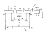
ところで加熱殺菌装置(UHT)18は、加熱部12と、ホールディングチューブ14と、第一段冷却部15と、第二段冷却部16とを含み、このうち加熱部12と第一段冷却部15との間に、第一段冷却部15からの熱水、例えば110℃の熱水を加熱部12へ供給する熱水ライン31が接続されている。さらに加熱部12からの冷却水、例えば40℃の冷却水を第一段冷却部15へ供給する冷却ライン32が接続されている。また第二段冷却部16には、冷却水、例えば10℃の冷却水を供給する冷却ライン37が接続されている。
By the way, the heat sterilization apparatus (UHT) 18 includes a
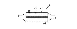
またUHT18の加熱部12と、第一段冷却部15と、第二段冷却部16は、図3に示すように、いずれも外筒41と外筒41内に多数配置されたチューブ42とを含むshell-tube型の熱交換器40からなる。そして外筒41内を飲料が流れ、チューブ内42を熱水または冷却水が流れて外筒41内で飲料を加熱したり冷却したりするようになっている。
Further, as shown in FIG. 3, the
また、加熱部12と第一段冷却部15との間に接続された熱水ライン31と冷却ライン32は、密閉された循環ライン30を構成している。すなわち熱水ライン31は加熱部12に接続された後、冷却ライン32と合流し、この冷却ライン32は第一段冷却部15に接続されて熱水ライン31に接続され、これら熱水ライン31と冷却ライン32は外部から閉ざされた密閉ラインを構成する。
Further, the
また熱水ライン31には、この熱水ライン31中に加熱蒸気を供給する加熱蒸気供給部34が設けられ、この加熱蒸気供給部34から供給される加熱蒸気により熱水ライン31中を流れる例えば110℃の熱水を高温、例えば150℃まで加熱させて熱水を無菌水とするようになっている。さらに冷却水ライン32には冷却水を加圧する加圧ポンプ35が設けれている。
Further, the
このようにして循環ライン30を流れる熱水および冷却水は、無菌状態に保たれている。さらに冷却ライン32には連結ライン33が接続され、冷却水ライン32内を流れる無菌水をこの連結ライン33を介してフィラー2側へ供給するようになっている。また、冷却ライン32には、補給水ライン32Aから補給水が補給される。
Thus, the hot water and the cooling water flowing through the
この場合、連結ライン33は、フィラー2の無菌チャンバ3に、噴霧器もしくはノズル3aを介して接続され、連結ライン33を流れる無菌水は噴霧器もしくはノズル3aを介して無菌チャンバ3内に供給される。
In this case, the connecting
次にこのような構成からなる本実施の形態の作用について説明する。 Next, the operation of the present embodiment having such a configuration will be described.
まず、飲料が調合装置1において調合され、バランスタンク5から加熱殺菌装置(UHT)18に送られ、この加熱殺菌装置18において飲料に対して加熱殺菌処理が施される。
First, a beverage is prepared in the
そして加熱殺菌装置18において加熱殺菌処理された飲料は、その後、サージタンク19に貯えられた後、ヘッドタンク11へ送られる。次にヘッドタンク11内の飲料はフィラー2に供給され、フィラー2内の充填ノズル2aを通って、ボトルb内へ無菌状態で充填される。次に飲料が充填されたボトルbは、フィラー2から外方へ排出される。
Then, the beverage subjected to the heat sterilization treatment in the
次に加熱殺菌装置18における作用について以下詳述する。
Next, the operation of the
まず図1に示すように、バランスタンク5から供給された飲料は加熱殺菌装置18の加熱部12へ送られ、この加熱部12において例えば常温(20℃)の飲料が例えば130℃まで加熱される。このように20℃から130℃まで飲料が加熱される間、この飲料に対する加熱殺菌処理が行なわれる。
First, as shown in FIG. 1, the beverage supplied from the balance tank 5 is sent to the
次に加熱部12において加熱された飲料は、ホールディングチューブ14内で図示しない加熱機構により目標温度、例えば130℃まで保温乃至加熱される。
Next, the beverage heated in the
次にホールディングチューブ14からの飲料は、第一段冷却部15において冷却され、その温度は例えば130℃から例えば60℃まで降下する。
The beverage from the holding
更に第一段冷却部15により冷却された飲料は、第二段冷却部16により更に冷却され、その温度は例えば60℃から例えば30℃まで降下する。
Furthermore, the beverage cooled by the first
次に第二段冷却部16により冷却された飲料は、マニホルドバルブ8を介してサージタンク19へ送られる。
Next, the beverage cooled by the second stage cooler 16 is sent to the
この間、加熱部12内に、熱水ライン31を流れる高温、例えば150℃の高温水(熱水)が供給され、この加熱部12において飲料を加熱する。加熱部12において飲料を加熱する熱水は、温度が例えば40℃まで降下して冷却水となって、冷却水ライン32を流れる。次に冷却水ライン32の冷却水は、加圧ポンプ35により加圧されて第一段冷却部15へ供給され第一段冷却部15において、高温の飲料を冷却する。第一段冷却部15において、冷却水はその温度が例えば40℃から110℃まで上昇して高温水(熱水)となり、熱水ライン31内に入る。
During this time, high temperature water (hot water, for example, 150 ° C.) flowing through the
次に熱水ライン31内を流れる熱水に対して加熱蒸気供給部34から加熱蒸気が供給され、熱水の温度は例えば110℃から150℃まで上昇する。
Next, heating steam is supplied from the heating
図1に示す熱水ライン31と冷却水ライン32とからなる循環ライン30は、外部から密閉された密閉ラインとなっているため、循環ライン30内を流れる熱水及び冷却水は無菌状態に保たれている。
The
この間、必要に応じて冷却水ライン32内を流れる無菌の冷却水を連結ライン33を介してフィラー2側へ供給する。連結ライン33は、フィラー2の無菌チャンバ3に、噴霧器3aを介して接続されているため、連結ライン33を流れる無菌の冷却水は噴霧器3aを介して無菌チャンバ3内に噴霧され、無菌チャンバ3内を無菌状態に維持している。
During this time, as needed, aseptic cooling water flowing in the
以上のように本実施の形態によれば、循環ライン30の冷却水ライン32内の無菌の冷却水を連結ライン33によりフィラー2側へ供給して、無菌チャンバ3内に噴霧することにより無菌チャンバ3内を無菌状態に保つことができる。このため無菌チャンバ3内に無菌水を供給するため、別個に無菌水生成機を設ける必要がなく、全体として設備コストおよび運転コストの低減を図ることができる。
As described above, according to the present embodiment, the sterile cooling water in the
1A…無菌充填システム
1…調合装置
2…フィラー
2a…充填ノズル
3…無菌チャンバ
3a…噴霧器
5…バランスタンク
6…帰還路
7…飲料供給系配管
7a…上流側配管部
7b…下流側配管部
7c…連結配管部
11…ヘッドタンク
12…加熱部
14…ホールディングチューブ
15…第一段冷却部
16…第二段冷却部
18…加熱殺菌装置
30…循環ライン
31…熱水ライン
32…冷却水ライン
33…連結ライン
34…加熱蒸気供給部
35…加圧ポンプ
37…冷却水ライン
1A ...
DESCRIPTION OF SYMBOLS 5 ... Balance tank 6 ... Return
15 First Stage Cooling Unit
DESCRIPTION OF
34 ... heating
Claims (2)
前記加熱殺菌装置で加熱殺菌された内容物をボトル内に充填する充填機とを備え、
前記加熱殺菌装置は内容物を加熱する加熱部と、前記加熱部により加熱された内容物を冷却する冷却部とを有し、
前記加熱部と前記冷却部との間に、前記冷却部からの熱水を前記加熱部へ供給する熱水ラインと、前記加熱部からの冷却水を前記冷却部へ供給する冷却ラインとを含み無菌水を循環させる循環ラインを接続し、
前記冷却部により前記内容物を冷却した後の前記熱水を前記熱水ラインを介して前記加熱部に供給して、この加熱部で前記内容物を前記熱水で加熱し、
前記加熱部により前記内容物を加熱した後の前記冷却水を前記冷却ラインを介して前記冷却部に供給して、この冷却部で前記内容物を前記冷却水で冷却し、
前記冷却ラインに前記充填機側へ無菌水を供給する連結ラインを設け、
前記充填機は無菌チャンバを含み、前記連結ラインは前記無菌チャンバに噴霧器あるいはノズルを介して接続されて、この噴霧器あるいはノズルにより前記無菌チャンバ内に無菌水を噴霧する、無菌充填システム。 A heat sterilizer for heat sterilizing the contents;
And a filling machine for filling the contents heated and sterilized by the heat sterilization apparatus into a bottle,
The heat sterilization apparatus has a heating unit for heating the contents, and a cooling unit for cooling the contents heated by the heating unit.
A hot water line for supplying hot water from the cooling unit to the heating unit and a cooling line for supplying cooling water from the heating unit to the cooling unit are included between the heating unit and the cooling unit. Connect a circulation line to circulate sterile water,
The hot water after the content is cooled by the cooling unit is supplied to the heating unit through the hot water line, and the heating unit heats the content with the hot water.
The cooling water after heating the contents by the heating unit is supplied to the cooling unit through the cooling line, and the cooling unit cools the contents with the cooling water.
A connection line for supplying sterile water to the filling machine side is provided in the cooling line ,
The aseptic filling system, wherein the filling machine includes a sterile chamber, the connection line is connected to the sterile chamber through a sprayer or a nozzle, and the sprayer or nozzle sprays sterile water into the sterile chamber.
Priority Applications (5)
| Application Number | Priority Date | Filing Date | Title |
|---|---|---|---|
| JP2017131463A JP6521396B2 (en) | 2017-07-04 | 2017-07-04 | Aseptic filling system |
| US16/620,109 US11203514B2 (en) | 2017-07-04 | 2018-06-28 | Aseptic filling system |
| EP18827605.9A EP3650401B1 (en) | 2017-07-04 | 2018-06-28 | Aseptic filling system |
| PCT/JP2018/024512 WO2019009169A1 (en) | 2017-07-04 | 2018-06-28 | Sterile filling system |
| CN201880044004.6A CN110831888B (en) | 2017-07-04 | 2018-06-28 | Aseptic filling system |
Applications Claiming Priority (1)
| Application Number | Priority Date | Filing Date | Title |
|---|---|---|---|
| JP2017131463A JP6521396B2 (en) | 2017-07-04 | 2017-07-04 | Aseptic filling system |
Publications (2)
| Publication Number | Publication Date |
|---|---|
| JP2019014497A JP2019014497A (en) | 2019-01-31 |
| JP6521396B2 true JP6521396B2 (en) | 2019-05-29 |
Family
ID=64950933
Family Applications (1)
| Application Number | Title | Priority Date | Filing Date |
|---|---|---|---|
| JP2017131463A Active JP6521396B2 (en) | 2017-07-04 | 2017-07-04 | Aseptic filling system |
Country Status (5)
| Country | Link |
|---|---|
| US (1) | US11203514B2 (en) |
| EP (1) | EP3650401B1 (en) |
| JP (1) | JP6521396B2 (en) |
| CN (1) | CN110831888B (en) |
| WO (1) | WO2019009169A1 (en) |
Families Citing this family (1)
| Publication number | Priority date | Publication date | Assignee | Title |
|---|---|---|---|---|
| JP6819709B2 (en) * | 2019-03-01 | 2021-01-27 | 大日本印刷株式会社 | Container sterilizer, content filling system, container sterilization method and content filling method |
Family Cites Families (16)
| Publication number | Priority date | Publication date | Assignee | Title |
|---|---|---|---|---|
| JPS5837161B2 (en) * | 1979-11-12 | 1983-08-15 | 東洋製罐株式会社 | Filling method and device for solid beverages |
| JP3315918B2 (en) * | 1998-01-23 | 2002-08-19 | 大日本印刷株式会社 | Sterilization method of filling machine and sterilization apparatus therefor |
| CN100457600C (en) * | 2002-12-12 | 2009-02-04 | 三得利株式会社 | Liquid filling method and liquid filling device |
| JP2007022600A (en) * | 2005-07-19 | 2007-02-01 | Toyo Seikan Kaisha Ltd | Method for cleaning and sterilizing pipe system of filling machine in food filling system |
| CN101306726B (en) * | 2007-05-18 | 2011-05-18 | 上海斯开龙包装有限公司 | Sterile filling and packaging machine |
| JP4737467B2 (en) * | 2009-02-27 | 2011-08-03 | 東洋製罐株式会社 | Aseptic filling of carbon dioxide containing liquid |
| JP5472627B2 (en) | 2010-06-10 | 2014-04-16 | 大日本印刷株式会社 | Aseptic filling method and apparatus |
| DE102011082286A1 (en) | 2011-09-07 | 2013-03-07 | Krones Aktiengesellschaft | Method and apparatus for heating a liquid product |
| ITPD20120329A1 (en) * | 2012-11-06 | 2014-05-07 | Sovema Spa | PLANT AND PROCEDURE FOR ELECTROCHEMICAL TRAINING OF LEAD-ACID ACCUMULATORS |
| JP6222110B2 (en) * | 2012-12-21 | 2017-11-01 | 大日本印刷株式会社 | Beverage filling method |
| JP5574025B1 (en) | 2013-06-25 | 2014-08-20 | 大日本印刷株式会社 | Sterilization method and apparatus for beverage supply system piping |
| CN103948110B (en) * | 2014-04-30 | 2016-06-29 | 程礼华 | The production equipment of a kind of aid digestion fruit-vegetable juice beverage and operating procedure thereof |
| JP5804152B2 (en) * | 2014-07-03 | 2015-11-04 | 大日本印刷株式会社 | Sterilization method and apparatus for beverage supply system piping |
| JP5920433B2 (en) * | 2014-09-25 | 2016-05-18 | 大日本印刷株式会社 | Method and apparatus for sterilizing filling nozzle |
| EP4129505A1 (en) * | 2015-12-22 | 2023-02-08 | Dai Nippon Printing Co., Ltd. | Method cleaning and sterilizing a product filling apparatus |
| DE102017104313A1 (en) * | 2017-03-01 | 2018-09-06 | Krones Ag | Device for filling a container with a sterilized filling product |
-
2017
- 2017-07-04 JP JP2017131463A patent/JP6521396B2/en active Active
-
2018
- 2018-06-28 US US16/620,109 patent/US11203514B2/en active Active
- 2018-06-28 CN CN201880044004.6A patent/CN110831888B/en active Active
- 2018-06-28 EP EP18827605.9A patent/EP3650401B1/en active Active
- 2018-06-28 WO PCT/JP2018/024512 patent/WO2019009169A1/en unknown
Also Published As
| Publication number | Publication date |
|---|---|
| EP3650401A1 (en) | 2020-05-13 |
| JP2019014497A (en) | 2019-01-31 |
| EP3650401A4 (en) | 2021-04-07 |
| US20200198955A1 (en) | 2020-06-25 |
| CN110831888B (en) | 2022-08-12 |
| WO2019009169A1 (en) | 2019-01-10 |
| CN110831888A (en) | 2020-02-21 |
| EP3650401B1 (en) | 2023-10-04 |
| US11203514B2 (en) | 2021-12-21 |
Similar Documents
| Publication | Publication Date | Title |
|---|---|---|
| JP5910765B2 (en) | Method and apparatus for aseptic filling of beverages | |
| JP5574025B1 (en) | Sterilization method and apparatus for beverage supply system piping | |
| JP6240674B2 (en) | Apparatus and method for manufacturing beverage containers | |
| US10039295B2 (en) | Method and device for heating a liquid product | |
| JP6449357B2 (en) | Beverage aseptic filling system | |
| WO2020090733A1 (en) | Cleaning method and cleaning device for heating sterilization system | |
| JP5804151B2 (en) | Sterilization method and apparatus for beverage supply system piping | |
| US20100193072A1 (en) | Filling device | |
| JP6135724B2 (en) | Sterilization method and apparatus for beverage supply system piping | |
| JP6521396B2 (en) | Aseptic filling system | |
| JP6086136B1 (en) | Aseptic filling system, container sterilization unit, and aseptic filling method | |
| JP5804150B2 (en) | Sterilization method and apparatus for beverage supply system piping | |
| WO2022138611A1 (en) | Beverage filling system and cip processing method | |
| US20210171364A1 (en) | Apparatus for producing and providing sterile water and method of operating the apparatus | |
| JP5804152B2 (en) | Sterilization method and apparatus for beverage supply system piping |
Legal Events
| Date | Code | Title | Description |
|---|---|---|---|
| A521 | Request for written amendment filed |
Free format text: JAPANESE INTERMEDIATE CODE: A523 Effective date: 20181108 |
|
| TRDD | Decision of grant or rejection written | ||
| A01 | Written decision to grant a patent or to grant a registration (utility model) |
Free format text: JAPANESE INTERMEDIATE CODE: A01 Effective date: 20190405 |
|
| A61 | First payment of annual fees (during grant procedure) |
Free format text: JAPANESE INTERMEDIATE CODE: A61 Effective date: 20190418 |
|
| R150 | Certificate of patent or registration of utility model |
Ref document number: 6521396 Country of ref document: JP Free format text: JAPANESE INTERMEDIATE CODE: R150 |