EP2567922A2 - Wachsvorrichtung, Spinneinheit und Spinnmaschine - Google Patents
Wachsvorrichtung, Spinneinheit und Spinnmaschine Download PDFInfo
- Publication number
- EP2567922A2 EP2567922A2 EP20120165118 EP12165118A EP2567922A2 EP 2567922 A2 EP2567922 A2 EP 2567922A2 EP 20120165118 EP20120165118 EP 20120165118 EP 12165118 A EP12165118 A EP 12165118A EP 2567922 A2 EP2567922 A2 EP 2567922A2
- Authority
- EP
- European Patent Office
- Prior art keywords
- wax
- section
- spacer plate
- spun yarn
- yarn
- Prior art date
- Legal status (The legal status is an assumption and is not a legal conclusion. Google has not performed a legal analysis and makes no representation as to the accuracy of the status listed.)
- Granted
Links
Images




Classifications
-
- B—PERFORMING OPERATIONS; TRANSPORTING
- B65—CONVEYING; PACKING; STORING; HANDLING THIN OR FILAMENTARY MATERIAL
- B65H—HANDLING THIN OR FILAMENTARY MATERIAL, e.g. SHEETS, WEBS, CABLES
- B65H71/00—Moistening, sizing, oiling, waxing, colouring or drying filamentary material as additional measures during package formation
- B65H71/005—Oiling, waxing by applying solid wax cake during spooling
-
- D—TEXTILES; PAPER
- D01—NATURAL OR MAN-MADE THREADS OR FIBRES; SPINNING
- D01H—SPINNING OR TWISTING
- D01H13/00—Other common constructional features, details or accessories
- D01H13/30—Moistening, sizing, oiling, waxing, colouring, or drying yarns or the like as incidental measures during spinning or twisting
- D01H13/308—Moistening, sizing, oiling, waxing, colouring, or drying yarns or the like as incidental measures during spinning or twisting by applying solids, e.g. wax
-
- B—PERFORMING OPERATIONS; TRANSPORTING
- B65—CONVEYING; PACKING; STORING; HANDLING THIN OR FILAMENTARY MATERIAL
- B65H—HANDLING THIN OR FILAMENTARY MATERIAL, e.g. SHEETS, WEBS, CABLES
- B65H2701/00—Handled material; Storage means
- B65H2701/30—Handled filamentary material
- B65H2701/31—Textiles threads or artificial strands of filaments
Definitions
- the present invention relates to a waxing device, a spinning unit, and a spinning machine.
- a waxing device described in Japanese Unexamined Patent Publication No. 2008-290872 is known.
- the waxing device is arranged so that an end surface of cylindrical wax makes contact with a travelling yarn.
- the travelling yarn makes contact with the end surface of the wax, and the wax is applied to the yarn.
- the wax is urged towards the end surface side in a rotation axis line direction to make contact with a tip-end of a spacer, and a position of the end surface of the wax is determined.
- a contacting state between the end surface of the wax and the yarn is determined, and an applied amount of the wax with respect to the yarn is determined.
- a plurality of adjustment plates is sandwiched between a spacer main body and a screw head, on which the spacer main body is placed, and by changing the number of the adjustment plates, a position of the tip-end of the spacer is shifted in a rotation axis line direction. Accordingly, the position of the end surface of the wax is moved in the rotation axis line direction, and the contacting state between the end surface of the wax and the yarn is changed.
- an operation of attaching and detaching the adjustment plate in the waxing device causes a great work load since the operation includes detaching a cover provided with the spacer, detaching the plurality of spacer main bodies, and sandwiching the adjustment plate.
- An object of the present invention is to provide a waxing device, a spinning unit, and a spinning machine adapted to facilitate an adjustment operation of an applied amount of wax with respect to a spun yarn.
- a waxing device includes a wax holding section, a wax contacting section, a supporting section, an urging member, and a positioning member.
- the wax holding section is adapted to hold a wax body to apply wax to a travelling spun yarn.
- the wax contacting section is provided to make contact with the wax body held by the wax holding section and adapted to position the wax body with respect to the spun yarn.
- the supporting section is adapted to movably support the wax contacting section.
- the urging member is adapted to urge the wax contacting section against the supporting section.
- the positioning member is adapted to position the wax contacting section with respect to the supporting section by being removably held by the wax contacting section and the supporting section urged by the urging member.
- the wax contacting section makes contact with the wax body to position the wax body, and a position of the wax contacting section with respect to the supporting section is determined by the positioning member.
- the wax contacting section is urged by the urging member, and the positioning member is held by the urged wax contacting section and the supporting section. Since the positioning member is removably held by the urged wax contacting section and the supporting section, the positioning member is not required to be fixed using a screw or the like. Therefore, the attachment and detachment operation of the positioning member is facilitated, and an adjustment operation of the position of the wax body can be easily carried out. As a result, an adjustment operation of an applied amount of the wax with respect to the yarn is facilitated.
- the wax contacting section includes a first end provided to make contact with the wax body, and a second end located away from the wax body. An urging force of the urging member is applied to the second end. The wax contacting section is urged in an appropriate direction by the urging force on the second end, and position accuracy of the wax contacting section is improved.
- the wax contacting section includes a cylindrical connecting section extending from the first end to the second end.
- the second end includes at least three claw sections provided to protrude in a radial direction from the connecting section and adapted to receive the urging force of the urging member.
- the urging force of the urging member is transmitted to the wax contacting section in a circumferential direction of the connecting section.
- the waxing device further includes a spun-yarn guiding section adapted to guide the spun yarn so that the spun yarn travels while making contact with a surface of the wax body located facing the wax contacting section.
- the first end includes three protrusions. Each of the three protrusions is formed substantially circular when viewed from a direction parallel to an advancing-and-receding direction of the wax contacting section with respect to the wax body, arranged in a circumferential direction, and formed protruding towards the wax body.
- the spun yarn makes contact with the surface of the wax body located facing the wax contacting section while passing through a yarn path avoiding the protrusion.
- a position of the surface facing the wax contacting section is stably fixed with the three protrusions.
- the wax is stably applied to the spun yarn. For example, even when the spun yarn is re-inserted into the yarn path after yarn breakage or the yarn cut, an insertion path of the spun yarn can be easily ensured since three protrusions are provided.
- the first end is provided with a rotation preventing means for preventing rotation of the wax contacting section in the circumferential direction with respect to the supporting section.
- the positioning member includes a spacer plate having a predetermined thickness and a spacer plate holding member.
- the spacer plate is adapted to adjust a position of the wax contacting section with respect to the supporting section.
- the spacer plate holding member is adapted to selectively hold the spacer plate of a plurality of types with different thickness, and detachably provided with respect to the wax contacting section while holding the spacer plate.
- the wax holding section and the wax contacting section position the wax body so that the spun yarn travels in a bent travelling path by making contact with the wax body.
- a thickness of the spacer plate held by the spacer plate holding member is thinner, bend of the travelling path of the spun yarn increases, and the applied amount of the wax to the spun yarn increases.
- the thickness of the spacer plate held by the spacer plate holding member is thicker, the bend of the travelling path of the spun yarn decreases, and the applied amount of the wax to the spun yarn decreases.
- the positioning member further includes a fixing member adapted to fix the spacer plate with respect to the spacer plate holding member.
- a fixing member adapted to fix the spacer plate with respect to the spacer plate holding member.
- the positioning member further includes a plate-thickness display section adapted to display the thickness of the spacer plate held by the spacer plate holding member. Since an operator can check the plate thickness display section to know the thickness of the spacer plate held by the spacer plate holding member, the adjustment operation of the position of the wax body can be more easily performed.
- the plate-thickness display section includes a display protrusion and an opening.
- the display protrusion is provided on the spacer plate and protrudes from a position associated with the thickness of the spacer plate.
- the opening is formed through the spacer plate holding member and externally exposes the display protrusion provided on the spacer plate held inside the spacer plate holding member.
- the position of the wax contacting section is displayed according to a position of the display protrusion exposed from the opening.
- the plate thickness display section can be realized with a simple configuration. Since the display protrusion is provided on the spacer plate itself, the plate thickness display section can accurately display the thickness of the spacer plate.
- a waxing device includes a wax holding section, a wax contacting section, a supporting section, a positioning member, and a position display section.
- the wax holding section is adapted to hold a wax body to apply wax to a travelling spun yarn.
- the wax contacting section is provided to make contact with the wax body held by the wax holding section and adapted to position the wax body with respect to the spun yarn.
- the supporting section is adapted to support the wax contacting section.
- the positioning member is provided between the wax contacting section and the supporting section and adapted to position the wax contacting section with respect to the supporting section.
- the position display section is adapted to display a position of the wax contacting section determined by the positioning member.
- the wax contacting section makes contact with the wax body to position the wax body.
- the position of the wax contacting section with respect to the supporting section is determined by the positioning member arranged between the wax contacting section and the supporting section. Since the position of the wax contacting section is displayed by the position display section, the position of the wax body can be easily checked. Therefore, the adjustment operation of the position of the wax body can be efficiently carried out. As a result, the adjustment operation of the applied amount of the wax with respect to the spun yarn is facilitated.
- the positioning member includes a spacer plate having a predetermined thickness and a spacer plate holding member.
- the spacer plate is adapted to adjust a position of the wax contacting section with respect to the supporting section.
- the spacer plate holding member is adapted to selectively hold the spacer plate of a plurality of types with different thickness, and detachably provided with respect to the wax contacting section while holding the spacer plate.
- the position display section displays a position of the wax contacting section by displaying information relating to the thickness of the spacer plate held by the spacer plate holding member. Thus, the thickness of the spacer plate held by the spacer plate holding member can be easily checked.
- a spinning unit includes a draft device, an air-jet spinning device, the waxing device having one of the above configurations, and a winding device.
- the draft device is adapted to draft a sliver into a fiber bundle.
- the air-jet spinning device is adapted to produce a spun yarn by spinning the fiber bundle drafted by the draft device using whirling airflow.
- the waxing device is adapted to apply the wax to the spun yarn spun by the air-j et spinning device.
- the winding device is adapted to wind the spun yarn, to which the wax is applied by the waxing device into a package.
- the spun yarn is produced by the air-jet spinning device that uses whirling airflow. Hairiness of the spun yarn, which has been spun by the whirling airflow, is less likely to fall off as compared to a ring yarn.
- the spinning unit adapted to apply the wax to the ring yarn of which the hairiness easily falls off, the hairiness that fell off attaches to the surface of the wax body, and the wax becomes difficult to be applied to the ring yarn.
- the hairiness of the spun yarn, which has been spun by the whirling airflow is less likely to fall off, the hairiness is less likely to be attached to the surface of the wax body, and the wax can be directly applied to the spun yarn.
- the spinning unit including the air-jet spinning device is preferable to adopt the configuration of the above-described waxing device adapted to apply the wax to the spun yarn with the applied amount being adjusted.
- the positioning member is removable by being inserted and removed from a front side. Since the operator can insert and remove the positioning member from a front side of the spinning unit for replacement, the adjustment operation of the position of the wax body can be easily performed.
- a spinning machine includes a plurality of the spinning units described above.
- the positioning member can be easily replaced, and the adjustment operation of the position of the wax body can be efficiently carried out in the entire spinning machine.
- the adjustment operation of the applied amount of the wax with respect to the spun yarn can be easily carried out.
- Upstream and downstream respectively refer to upstream and downstream in a travelling direction of a yarn during spinning.
- a spinning machine 1 illustrated in FIG. 1 includes a plurality of spinning units 2 arranged in line.
- the spinning machine 1 includes a yarn joining cart 3, a blower box 80, and a motor box 5.
- a work passage extending in a direction in which the spinning units 2 are arranged is provided to the front in the depth direction of FIG. 1 when viewed from the spinning machine 1. The operator can perform operation, monitoring, and the like of each spinning unit 2 from the work passage.
- each spinning unit 2 includes a draft device 7, an air-jet spinning device 9, a yarn slack eliminating device (yarn accumulating device) 12, a waxing device 100, and a winding device 13 arranged in this order from upstream to downstream.
- the draft device 7 is arranged in proximity to an upper end of a housing 6 of the spinning machine 1.
- a fiber bundle 8 fed from the draft device 7 is spun by the air-jet spinning device 9.
- a spun yarn 10 fed from the air-jet spinning device 9 is passed through a yarn clearer 52, to be described later, fed further downstream by the yarn slack eliminating device 12, and applied with wax in the waxing device 100. Thereafter, the spun yarn 10 is wound by the winding device 13, and a package 45 is formed.
- the draft device 7 drafts a sliver 15 to obtain the fiber bundle 8.
- the draft device 7 includes four roller pairs, i.e. , a back roller pair 16, a third roller pair 17, a middle roller pair 19 provided with an apron belt 18, and a front roller pair 20.
- a bottom roller of each of the roller pairs 16, 17, 19, and 20 is driven by power from the motor box 5, or by power of electric motors (not illustrated) arranged in each spinning unit 2.
- Each of the roller pairs 16, 17, 19, and 20 is driven with a different rotation speed.
- the draft device 7 can draft the sliver 15 supplied from the upstream to form the fiber bundle 8, and feed the fiber bundle 8 to the air-jet spinning device 9 located downstream.
- the air-jet spinning device 9 applies twists to the fiber bundle 8 using whirling airflow to produce the spun yarn 10.
- the air-jet spinning device 9 includes a fiber guiding section, a whirling airflow generation nozzle, and a hollow guide shaft body.
- the fiber guiding section guides the fiber bundle 8 fed from the draft device 7 to a spinning chamber formed inside the air-jet spinning device 9.
- the whirling airflow generation nozzle is arranged at a periphery of a path of the fiber bundle 8 to generate the whirling airflow in the spinning chamber. This whirling airflow causes fiber ends of the fiber bundle 8 to be reversed and whirl in the spinning chamber.
- the hollow guide shaft body guides the spun yarn 10 from the spinning chamber to an outside of the air-jet spinning device 9.
- the yarn slack eliminating device 12 is arranged downstream of the air-jet spinning device 9.
- the yarn slack eliminating device 12 has a function of applying a predetermined tension to the spun yarn 10 to pull out the spun yarn 10 from the air-jet spinning device 9, a function of accumulating the spun yarn 10 fed from the air-jet spinning device 9 during a yarn joining operation by the yarn joining cart 3 to prevent slackening of the spun yarn 10, and a function of adjusting the tension so that a fluctuation of the tension at the winding device 13 side is not transmitted towards the air-jet spinning device 9. As illustrated in FIG.
- the yarn slack eliminating device 12 includes a slack eliminating roller (yarn accumulating roller) 21, a yarn hooking member 22, an upstream guide 23, an electric motor 25, a downstream guide 26, and a yarn accumulated amount detecting sensor 27.
- the yarn hooking member 22 can be engaged (hooked) with the spun yarn 10.
- the yarn hooking member 22 integrally rotates with the slack eliminating roller 21 while being engaged with the spun yarn 10 to wind the spun yarn 10 around an outer peripheral surface of the slack eliminating roller 21.
- the slack eliminating roller 21 can have a prescribed amount of the spun yarn 10 wound around the outer peripheral surface thereof to accumulate the spun yarn 10.
- the slack eliminating roller 21 is rotatably driven by the electric motor 25. When the slack eliminating roller 21 is rotated, the spun yarn 10 wound around the outer peripheral surface of the slack eliminating roller 21 is wound to tighten the slack eliminating roller 21, and the spun yarn 10 located upstream than the yarn slack eliminating device 12 is pulled.
- the yarn slack eliminating device 12 rotates the slack eliminating roller 21 at a predetermined rotation speed with the spun yarn 10 wound around the outer peripheral surface of the slack eliminating roller 21, a predetermined tension can be applied to the spun yarn 10 and the spun yarn 10 can be pulled out from the air-jet spinning device 9 at a predetermined speed and transported towards the downstream at a predetermined speed.
- a predetermined contacting area can be ensured between the slack eliminating roller 21 and the spun yarn 10.
- the slack eliminating roller 21 thus can hold and pull the spun yarn 10 at a sufficient force, and the yarn slack eliminating device 12 can pull the spun yarn 10 at a stable speed from the air-jet spinning device 9 without causing a slip or the like.
- other structures that applies a tension to the spun yarn 10 are not arranged between the air-jet spinning device 9 and the yarn slack eliminating device 12.
- a pull-out speed of the spun yarn 10 from the air-jet spinning device 9 is determined by the rotation speed of the slack eliminating roller 21.
- the tension is applied to the spun yarn 10 by the yarn slack eliminating device 12, and the spun yarn 10 can be pulled out from the air-jet spinning device 9 at an accurate speed with less variation.
- the yarn accumulated amount detecting sensor 27 detects, in a non-contacting manner, an accumulated amount of the spun yarn 10 accumulated on the slack eliminating roller 21, and transmits the accumulated amount to a unit controller (not illustrated).
- the upstream guide 23 is arranged slightly upstream of the slack eliminating roller 21.
- the upstream guide 23 appropriately guides the spun yarn 10 with respect to the outer peripheral surface of the slack eliminating roller 21.
- the upstream guide 23 prevents the twist of the spun yarn 10 propagating from the air-jet spinning device 9 from being transmitted downstream of the upstream guide 23.
- the yarn clearer 52 is arranged on a front side of the housing 6 of the spinning machine 1, and at a position between the air-jet spinning device 9 and the yarn slack eliminating device 12.
- the spun yarn 10 spun by the air-jet spinning device 9 is passed through the yarn clearer 52 before being wound by the yarn slack eliminating device 12.
- the yarn clearer 52 monitors the thickness of the travelling spun yarn 10, and when a yarn defect of the spun yarn 10 is detected, the yarn clearer 52 transmits a yarn defect detection signal to the unit controller.
- the unit controller Upon receiving the yarn defect detection signal, the unit controller immediately stops ejection of compressed air from the whirling airflow generation nozzle of the air-jet spinning device 9. The whirling airflow is then stopped, the twisting of the fiber bundle 8 is stopped, and introduction of the fiber bundle 8 to the air-jet spinning device 9 is also stopped. A continuation of the fibers is disconnected in the air-jet spinning device 9, and the spun yarn 10 is cut. Thereafter, the unit controller further stops the draft device 7 and the like. The unit controller transmits a control signal to the yarn joining cart 3, and the yarn joining cart 3 travels to the front of the spinning unit 2. Thereafter, the air-jet spinning device 9 and the like are driven again, the yarn joining cart 3 performs the yarn joining operation, and winding is resumed.
- the yarn joining cart 3 includes a splicer (yarn joining device) 43, a suction pipe 44, and a suction mouth 46.
- a splicer yarn joining device
- suction pipe 44 sucks and catches a yarn end fed from the air-jet spinning device 9 while being swung vertically with a shaft as a center, and guides the yarn end to the splicer 43.
- the suction mouth 46 sucks and catches a yarn end from the package 45 supported by the winding device 13 while being swung vertically with a shaft as the center, and guides the yarn end to the splicer 43.
- the splicer 43 joins the guided yarn ends.
- the waxing device 100 is arranged downstream of the yarn slack eliminating device 12.
- the waxing device 100 applies wax to the spun yarn 10 travelling from the yarn slack eliminating device 12 towards the winding device 13.
- the winding device 13 includes a cradle arm 71 supported to be swingable about a supporting shaft 70.
- the cradle arm 71 can rotatably support a bobbin 48 for winding the spun yarn 10.
- the winding device 13 includes a winding drum 72 and a traverse device 75.
- the winding drum 72 is adapted to be driven while making contact with an outer peripheral surface of the bobbin 48 or the outer peripheral surface of the package 45.
- the traverse device 75 includes a traverse guide 76 capable of being engaged with the spun yarn 10.
- the winding device 13 drives the winding drum 72 with an electric motor (not illustrated) while reciprocating the traverse guide 76 by a driving means (not illustrated).
- the package 45 making contact with the winding drum 72 can be rotated and the spun yarn 10 can be wound into the package 45 while being traversed.
- a traverse mechanism of the traverse device 75 is commonly driven in each spinning unit 2 by a common shaft for the plurality of spinning units 2.
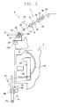
- the waxing device 100 described above will be more specifically described with reference to FIG. 3 and FIG. 4 .
- the waxing device 100 pushes one end surface of a wax body W against the travelling spun yarn 10 while rotating the wax body W about a rotation axis line A. Accordingly, the wax is applied to the spun yarn 10.
- An XYZ coordinate system may be set as illustrated in FIG. 3 , and X, Y, and/or Z may be used to describe a positional relationship of each section.
- a Z axis is parallel to a direction in which the spun yarn 10 is introduced to or from the waxing device 100.
- a Y axis coincides with a front and rear direction of the spinning machine 1 and the spinning unit 2.
- -Y side is the front side
- +Y side is the rear side.
- An X axis is parallel to a rotation axis line A of the wax body W.
- the X axis coincides with a direction in which the plurality of spinning units 2 are arranged in the spinning machine 1.
- the waxing device 100 includes the rotation shaft 101 provided with a cylindrical wax body W, a motor 103 adapted to rotate the rotation shaft 101, and a base (supporting section) 105 adapted to support each component including the motor 103.
- the base 105 is fixed to the housing 6 (see FIG. 2 ).
- the waxing device 100 includes a hold-down lever 107 for holding down the wax body W attached to the rotation shaft 101.
- the rotation shaft 101 and the hold-down lever 107 function as a wax holding section adapted to hold the wax body W.
- the hold-down lever 107 is urged backward (-X direction) by a spring (not illustrated).
- the hold-down lever 107 pushes the wax body W backward through a flange member 109 attached to a front end surface Wa of the wax body W.
- a back end surface Wb of the wax body W is made to contact against three protrusions 113p of a wax pin (wax contacting section) 113 arranged at back of the wax body W.
- a position of the wax pin 113 in the X direction is determined with respect to the base 105.
- the wax body W is positioned with respect to the base 105 in the X direction.
- the back end surface Wb of the wax body W is always located at the position of the tip-end of the three protrusions 113p of the wax pin 113.
- the tip-end of the three protrusions 113p are located on the same plane.
- the base 105 includes an upstream guiding section (spun-yarn guiding section) 105u formed above (+Z side) the rotation shaft 101, and a downstream guiding section (spun-yarn guiding section) 105d formed below (-z side) the rotation shaft 101.
- the upstream guiding section 105u guides the spun yarn 10 introduced into the waxing device 100 from the upstream.
- the downstream guiding section 105d guides the spun yarn 10 travelling downward from the waxing device 100.
- On the front side of the base 105 a slit extending from the front end of the plate of the base 105 to the upstream guiding section 105u and a slit extending from the front end of the plate of the base 105 to the downstream guiding section 105d are formed.
- the spun yarn 10 guided by the suction pipe 44 is inserted from the front side to the upstream guiding section 105u and the downstream guiding section 105d through the slits, and the spun yarn 10 returns to the predetermined yarn path.
- An imaginary line connecting the upstream guiding section 105u and the downstream guiding section 105d is parallel to the z axis, and passes through the -Y side of the three protrusions 113p of the wax pin 113.
- Such an imaginary line is located slightly on the +X side of the tip-end of the three protrusions 113p.
- the back end surface Wb of the wax body W is uniformly worn away.
- the hold-down lever 107 moves the wax body W backward along with the consumption of the wax body W.
- the back end surface Wb of the wax body W is always maintained at the same position.
- the applied amount of the wax with respect to the spun yarn 10 depends on the position in the X direction of the wax body W (position in the X direction of the back end surface Wb) with respect to the base 105 (the upstream guiding section 105u and the downstream guiding section 105d). As the back end surface Wb of the wax body W is located more on the -X side, the bend (bulge towards the -X direction) of the travelling path of the spun yarn 10 becomes greater. Since a force at which the back end surface Wb is pushed against the spun yarn 10 also becomes stronger, the applied amount of the wax with respect to the spun yarn 10 becomes greater. As the back end surface Wb of the wax body W is located more on the +X side, the bend of the travelling path of the spun yarn 10 becomes smaller. Since the force at which the back end surface Wb is pushed against the spun yarn 10 also becomes weaker, the applied amount of the wax with respect to the spun yarn 10 becomes smaller.
- the applied amount of the wax is required to be changed according to the specification of the package 45. Since fine tuning may be necessary, the position adjustment of the wax body W is preferably carried out with a simple operation. In the spinning machine 1 including a plurality of spinning units 2, since the position adjustment operation arises according to the number of spinning units 2, simplification of the operation greatly contributes to improvement of operation efficiency.
- the position of the wax body W (position of the back end surface Wb) is determined by making contact against the three protrusions 113p of the wax pin 113.
- the position adjustment of the wax body W includes adjusting the relative position of the wax pin 113 with respect to the base 105 in the X direction.
- the wax pin 113 is supported by the base 105 and is movable in an advancing-and-receding direction (the X direction) with respect to the wax body W.
- the position of the wax pin 113 in the X direction is adjustable.
- the wax pin 113 includes a front end portion (first end) 113a located on the side to make contact with the wax body W, a back end portion (second end) 113b located on the side away from the wax body W, and a cylindrical connecting portion 113c extending from the front end portion 113a to the back end portion 113b, and is integrally formed.
- the front end portion 113a is formed substantially circular when viewed in a direction parallel to the rotation axis line A, and includes three protrusions 113p protruding towards the wax body W.
- the three protrusions 113p are arranged on a circumference having the rotation axis line A as the center.
- the three protrusions 113p protrude at the same height in the +X direction so as to make contact with the back end surface Wb of the wax body W altogether.
- the front end portion 113a is provided with a rotation preventing protrusion (rotation preventing part) 113d protruding in the radial direction. A function of the rotation preventing protrusion 113d will be described later.
- a tubular shaft of the cylindrical connecting portion 113c coincides with the rotation axis line A.
- a shaft or the like of the motor 103 (not illustrated) is inserted to a hollow part of the cylindrical connecting portion 113c.
- the back end portion 113b is configured as a back end of the cylindrical connecting portion 113c.
- the back end portion 113b includes three claw sections 113q protruding in the radial direction from the outer peripheral surface of the cylindrical connecting portion 113c.
- the three claw sections 113q are arranged at a predetermined interval in a peripheral direction.
- the wax pin 113 is attached to the base 105, and is supported to be movable in the advancing-and-receding direction (the X direction) with respect to the wax body W.
- the base 105 includes a spacer unit receiving section 106 projecting out in the +X direction on the rotation axis line A.
- the back end portion 113b of the wax pin 113 is inserted to a hole at a center of the spacer unit receiving portion 106.
- the wax pin 113 is movable front and back in the X direction while moving the outer peripheral surface of the cylindrical connecting portion 113c to slide against the inner surface of the hole of the spacer unit receiving section 106.
- the claw sections 113q of the wax pin 113 are urged in the -X direction with respect to the base 105 by a compression spring (urging member) 119 incorporated between the claw sections 113q and the spacer unit receiving section 106. Only one claw section 113q is illustrated in the cross-sectional view of FIG. 7 .
- the other two claw sections 113q also have a similar structure and are urged in the -X direction.
- the three claw sections 113q are arranged at a predetermined interval in the peripheral direction.
- the wax pin 113 as a whole, is urged in the -X direction in the peripheral direction, and the position accuracy of the wax pin 113 is high.
- the number of claw sections 113q is not limited to three, and four or more claw sections 113q may be formed as long as the claw sections 113q are arranged at a predetermined interval in the peripheral direction.
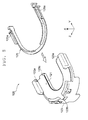
- a spacer unit 120 determines the position of the wax pin 113 with respect to the base 105 in the X direction. As illustrated in FIG. 6 and FIG. 7 , the spacer unit 120 is sandwiched between the wax pin 113 urged in the -X direction and the spacer unit receiving section 106. As illustrated in FIG. 8 , the spacer unit 120 has a horseshoe shape with the rear side (the +Y side) opened.
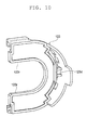
- the spacer unit 120 includes a thin-plate shaped spacer plate 121 (see FIG. 11 ), a spacer plate holder (spacer plate holding member) 123 for holding the spacer plate 121, and a fixing tool (fixing member) 125 for fixing the spacer plate 121 to the spacer plate holder 123.
- the spacer plate 121, the spacer plate holder 123, and the fixing tool 125 all have a horseshoe shape.
- the spacer plate 121 is mounted on a mounting surface 123c of the spacer plate holder 123.
- the fixing tool 125 is attached to the spacer plate holder 123 so as to hold down the outer edge part of the spacer plate 121 with the fixing tool 125.
- a protruding portion 125a formed at both ends of the fixing tool 125 is fitted into a recess 123a at a corresponding area of the spacer plate holder 123.
- the fixing tool 125 is thus not easily separated from the spacer plate holder 123.
- the spacer plate 121 held down with the fixing tool 125 also does not easily fall off from the spacer plate holder 123.
- the spacer unit 120 is inserted between the spacer unit receiving section 106 and the wax pin 113 of the base 105, and is detachably attached.
- the operator pulls the wax pin 113 in the +X direction against the urging force of the compression spring 119 to set the spacer unit 120 at a predetermined position, and then releases the wax pin 113, to attach the spacer unit 120.
- the operator detaches the spacer unit 120 by a reverse operation.
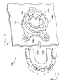
- one part of the spacer plate holder 123 and the spacer plate 121 are sandwiched between a back surface 113t of the front end portion 113a of the wax pin 113 and a front surface 106h of the spacer unit receiving section 106.
- An inner edge part 123r of the spacer plate holder 123 illustrated in FIG. 9 is engaged with a step 106r formed on the front surface 106h to fix the position of the spacer plate holder 123 in the Z direction.
- a protruding section 123d is provided on the spacer plate holder 123. The protruding section 123d protrudes towards the spacer unit receiving section 106. As also illustrated in FIG.
- a cutout 123b is formed in the spacer plate holder 123 (see FIG. 6 and FIG. 8 ).
- the rotation preventing protrusion 113d of the wax pin 113 is fitted into the cutout 123b. Accordingly, the rotation of the wax pin 113 about the rotation axis line A with respect to the spacer unit 120 is prevented. As a result, the rotation of the wax pin 113 about the rotation axis line A with respect to the base 105 is prevented.
- the inner edge part 123r, the step 106r, the protruding section 123d, the recessed groove 106k, the cutout 123b, and the rotation preventing protrusion 113d configure a rotation preventing means for preventing the rotation of the wax pin 113 about the rotation axis line A with respect to the base 105.
- a gap between the back surface 113t of the front end portion 113a of the wax pin 113 and the front surface 106h of the spacer unit receiving section 106 is determined.
- the relative position of the wax pin 113 with respect to the base 105 in the X direction is determined.
- a thickness of the spacer plate 121 is to be adjusted.
- the spacer plate 121 of various thicknesses is prepared.
- the operator appropriately selects the spacer plate 121 to be set in the spacer unit 120 to adjust the position of the wax pin 113 in the X direction according to the plate thickness of the spacer plate 121.
- Protruding portions (display protrusions) 122a, 122b, and 122c enabling distinguishment of the plate thickness according to the formed position are respectively formed on each of the spacer plates 121a, 121b, and 121c having a different plate thickness.
- the protruding position of the protruding portions 122a, 122b, and 122c is associated with the plate thickness of each of the spacer plates 121a, 121b, and 121c.
- the protruding portion 122a of the spacer plate 121a having a plate thickness of 0.2 mm protrudes at a lower position.
- openings 123h, 123j, and 123k are formed in the spacer plate holder 123 (see FIG. 6 ).
- Each of the openings 123h, 123j, and 123k are formed through a wall surface of the spacer plate holder 123 so that the protruding portions 122a, 122b, and 122c can be respectively inserted.
- Each of the protruding portions 122a, 122b, and 122c protrudes outward from each of the openings 123h, 123j, and 123k, and can be viewed from the front side of the spinning unit 2.
- the "front side” of the spinning unit 2 refers to a side facing the work passage at an installed location of the spinning machine 1.
- the plate thickness of the spacer plate 121 and the position of the wax pin 113 in the X direction are displayed.
- the protruding portion 122a protrudes from the opening 123h
- the operator can know that the spacer plate 121a having a plate thickness of 0.2 mm is set.
- the operator visibly checks each of the openings 123h, 123j, and/or 123k from the work passage to know the spacer plate 121 having which thickness is set in the spacer unit 120.
- the protruding portions 122a, 122b, and/or 122c formed on the spacer plate 121, and the openings 123h, 123j, and/or 123k formed in the spacer plate holder 123 configure a plate thickness display section.
- the plate thickness display section displays the plate thickness of the spacer plate 121 set in the spacer unit 120.
- the plate thickness display section indirectly displays the position of the wax pin 113, the position of the wax body W, and the applied amount of the wax with respect to the spun yarn 10.
- the plate thickness display section configures a position display section.
- the spacer unit 120 attached or detached during the adjustment of the position of the wax body W is sandwiched and held by the urged wax pin 113 and the base 105, the spacer unit 120 is not required to be fixed using a screw and the like. With a simple operation of pulling the wax pin 113 in the +X direction against the urging force, the attachment and detachment operation of the spacer unit 120 can be easily carried out without any tool.
- the position of the wax pin 113 in the X direction is adjusted with a simple method of selecting and changing the spacer plate 121 having a plate thickness to be set in the spacer unit 120.
- the position of the wax body W and the back end surface Wb in the X direction is adjusted, and the applied amount of the wax with respect to the spun yarn 10 is adjusted.
- the operator can easily adjust the position of the wax body W, and can easily adjust the applied amount of the wax with respect to the spun yarn 10.
- the spacer unit 120 has a horseshoe shape in which the rear side (the +Y side) is opened.
- the wax body W and the wax pin 113 are not necessary to be removed from the rotation shaft 101.
- the spacer unit 120 can be detachably inserted or removed in the Y direction from the front side of the spinning machine 1 or the front side of the spinning unit 2, and the operator can easily adjust the position of the wax body W.
- the horseshoe shape of the spacer unit 120 contributes to efficiency in adjusting the applied amount of the wax.
- the back surface 113t of the wax pin 113 is reliably made contact against the spacer unit 120 by the urging force of the compression spring 119.
- the position accuracy of the wax pin 113 is thus improved, and the position accuracy of the wax body W is improved.
- the urging force of the compression spring 119 acts on the three claw sections 113q of the back end portion 113b of the wax pin 113.
- the wax pin 113 as a whole, is urged in the -X direction in the peripheral direction.
- the protrusions 113p evenly make contact with the back end surface Wb of the wax body W, and the position accuracy of the back end surface Wb is improved.
- the wax pin 113 makes contact with the back end surface Wb of the wax body W at three points.
- the back end surface Wb of the wax body W is thus stably positioned in the X direction.
- the wax is stably applied to the spun yarn 10.
- the imaginary line connecting the upstream guiding section 105u and the downstream guiding section 105d passes the -Y side of all of the three protrusions 113p of the wax pin 113.
- the three protrusions 113p all exist on the rear side (the +Y side) of the yarn path in the waxing device 100. After the yarn breakage or the yarn cut, the spun yarn 10 to be re-inserted to the yarn path is smoothly inserted from the front side (the -Y side) without interfering with the protrusions 113p. Since the number of protrusions 113p is three, the insertion path of the spun yarn 10 to the yarn path as described above can be easily ensured.
- the rotation preventing means described above prevents the rotation of the wax pin 113 about the rotation axis line A with respect to the base 105.
- the wax pin 113 is prevented from being dragged by the rotation of the wax body W.
- the wax can be stably applied to the spun yarn 10.
- the spacer unit 120 includes the fixing tool 125 for positioning and fixing the spacer plate 121 to the spacer plate holder 123.
- the spacer plate 121 is less likely to fall off, and the attachment or detachment operation of the spacer unit 120 can be smoothly carried out.
- the spacer unit 120 includes a plate thickness display section configured by the protruding portions 122a, 122b, and 122c, and the openings 123h, 123j, and 123k. By looking at the plate thickness display section, the operator can know the plate thickness of the currently set spacer plate 121, and can more easily adjust the position of the wax body W.
- the plate thickness display section can be realized with a simple structure of the protruding portions 122a, 122b, and 122c, and the openings 123h, 123j, and 123k.
- the protruding portions 122a, 122b, and 122c are arranged on the spacer plate 121 itself. Possibility that the spacer plate thickness is mistakenly displayed is low, and the thickness of the spacer plate 121 can be accurately known.
- the spun yarn 10 is produced by the air-jet spinning device 9 using the whirling airflow.
- the spun yarn 10 spun by the whirling airflow is less likely to have the hairiness fall off as compared to the ring yarn.
- the hairiness that fell off attaches to the surface of the wax, and the wax becomes difficult to be applied to the ring yarn.
- the hairiness of the spun yarn 10 spun by the whirling airflow is less likely to fall off and the hairiness is less likely to attach to the surface of the wax body W, the wax can be directly applied to the spun yarn 10.
- the spinning unit 2 including the air-jet spinning device 9 is preferable to adopt the waxing device 100 described above that applies the wax to the spun yarn 10 with the applied amount being adjusted.
- the spacer unit 120 can be easily replaced, and the adjustment operation of the position of the wax body W can be efficiently carried out in the entire spinning machine 1.
- the spun yarn 10 is pulled out from the air-jet spinning device 9 by the slack eliminating roller 21 that winds and accumulates a prescribed amount of the spun yarn 10.
- the present invention may be applied to the spinning machine and the spinning unit in which the spun yarn is pulled out from the air-jet spinning device with the delivery roller and the nip roller.
- the whirling airflow of the air-jet spinning device 9 is stopped when the yarn defect is detected, and the spun yarn 10 is cut.
- the present invention may be applied to a spinning machine and a spinning unit in which a yarn is cut using a cutter.
- the yarn path is arranged such that the spun yarn 10 travels downward from the draft device 7 at the upper part towards the winding device 13 at the lower part in a machine height direction.
- the present invention may be applied to a spinning machine and a spinning unit in which a yarn path is arranged to travel from bottom to top in the machine height direction.
- the air-jet spinning device 9 may include a needle held by the fiber guiding section, and arranged to protrude into the spinning chamber.
- the needle prevents the twists of the fiber bundle 8 from being propagated towards the upstream of the air-jet spinning device 9.
- the air-jet spinning device 9 may prevent the propagation of the twist of the fiber bundle 8 by a downstream end of the fiber guiding section.
- the air-jet spinning device 9 may include a pair of air-jet nozzles adapted to apply twists in opposite directions from each other.
- the bottom rollers of the draft device 7 and the traverse mechanism of the traverse device 75 are commonly driven for each spinning unit 2.
- the present invention may be applied to a spinning machine and a spinning unit in which each section of the spinning unit (e.g., the draft device, the air-jet spinning device, the yarn winding device, or the like) is independently driven for each spinning unit 2.
- the waxing device 100 is arranged in the spinning unit 2 including the air-jet spinning device 9.
- the present invention is not limited to the embodiment described above, and the waxing device 100 may be provided in another yarn winding machine adapted to wind a yarn into a package while applying wax, such as an automatic winder.
Landscapes
- Engineering & Computer Science (AREA)
- Mechanical Engineering (AREA)
- Textile Engineering (AREA)
- Chemical & Material Sciences (AREA)
- Oil, Petroleum & Natural Gas (AREA)
- Spinning Or Twisting Of Yarns (AREA)
Applications Claiming Priority (1)
| Application Number | Priority Date | Filing Date | Title |
|---|---|---|---|
| JP2011196332A JP2013057144A (ja) | 2011-09-08 | 2011-09-08 | ワキシング装置、紡績ユニット及び紡績機 |
Publications (3)
| Publication Number | Publication Date |
|---|---|
| EP2567922A2 true EP2567922A2 (de) | 2013-03-13 |
| EP2567922A3 EP2567922A3 (de) | 2015-05-20 |
| EP2567922B1 EP2567922B1 (de) | 2017-05-31 |
Family
ID=46026680
Family Applications (1)
| Application Number | Title | Priority Date | Filing Date |
|---|---|---|---|
| EP12165118.6A Not-in-force EP2567922B1 (de) | 2011-09-08 | 2012-04-23 | Wachsvorrichtung, Spinneinheit und Spinnmaschine |
Country Status (3)
| Country | Link |
|---|---|
| EP (1) | EP2567922B1 (de) |
| JP (1) | JP2013057144A (de) |
| CN (1) | CN102995191B (de) |
Cited By (3)
| Publication number | Priority date | Publication date | Assignee | Title |
|---|---|---|---|---|
| CN109733959A (zh) * | 2018-12-20 | 2019-05-10 | 蔓莎(苏州)工艺制品有限公司 | 加棉芯机 |
| CN109898199A (zh) * | 2018-04-04 | 2019-06-18 | 里特机械公司 | 纺织机械的上蜡方法、上蜡设备以及此类纺织机械 |
| CN115418810A (zh) * | 2022-09-21 | 2022-12-02 | 歙县博升纺织(集团)有限公司 | 一种纺织纱线表面上蜡设备 |
Families Citing this family (5)
| Publication number | Priority date | Publication date | Assignee | Title |
|---|---|---|---|---|
| CN103738797B (zh) * | 2013-12-10 | 2016-06-08 | 苏州瑞日纺织科技有限公司 | 一种络筒机的纱线上蜡装置 |
| DE102017116938A1 (de) * | 2017-07-26 | 2019-01-31 | Saurer Spinning Solutions Gmbh & Co. Kg | Führungsbolzen für einen Paraffinkörper |
| CN107601172A (zh) * | 2017-10-17 | 2018-01-19 | 威海上进纺织机械有限公司 | 一种用于络筒机的动态上蜡装置 |
| JP2020007075A (ja) * | 2018-07-05 | 2020-01-16 | 村田機械株式会社 | 糸巻取機 |
| JP2022026121A (ja) * | 2020-07-30 | 2022-02-10 | 村田機械株式会社 | 糸巻取機 |
Citations (1)
| Publication number | Priority date | Publication date | Assignee | Title |
|---|---|---|---|---|
| JP2008290872A (ja) | 2007-05-28 | 2008-12-04 | Murata Mach Ltd | ワキシング装置 |
Family Cites Families (4)
| Publication number | Priority date | Publication date | Assignee | Title |
|---|---|---|---|---|
| CH422610A (de) * | 1965-03-19 | 1966-10-15 | Schweiter Ag Maschf | Paraffiniervorrichtung an Spulmaschine |
| IT1146488B (it) * | 1981-06-26 | 1986-11-12 | Savio Spa | Perfezionamenti ai dispositivi paraffinatori e dispositivi paraffinatori cosi' perfezionati |
| JP2001270658A (ja) * | 2000-03-27 | 2001-10-02 | Murata Mach Ltd | 糸巻取装置のワキシング装置 |
| DE102006018838B4 (de) * | 2005-06-22 | 2012-09-20 | Oerlikon Textile Gmbh & Co. Kg | Paraffiniereinrichtung für eine Kreuzspulen herstellende Textilmaschine |
-
2011
- 2011-09-08 JP JP2011196332A patent/JP2013057144A/ja not_active Withdrawn
-
2012
- 2012-04-23 EP EP12165118.6A patent/EP2567922B1/de not_active Not-in-force
- 2012-05-16 CN CN201210152935.2A patent/CN102995191B/zh active Active
Patent Citations (1)
| Publication number | Priority date | Publication date | Assignee | Title |
|---|---|---|---|---|
| JP2008290872A (ja) | 2007-05-28 | 2008-12-04 | Murata Mach Ltd | ワキシング装置 |
Cited By (4)
| Publication number | Priority date | Publication date | Assignee | Title |
|---|---|---|---|---|
| CN109898199A (zh) * | 2018-04-04 | 2019-06-18 | 里特机械公司 | 纺织机械的上蜡方法、上蜡设备以及此类纺织机械 |
| CN109733959A (zh) * | 2018-12-20 | 2019-05-10 | 蔓莎(苏州)工艺制品有限公司 | 加棉芯机 |
| CN115418810A (zh) * | 2022-09-21 | 2022-12-02 | 歙县博升纺织(集团)有限公司 | 一种纺织纱线表面上蜡设备 |
| CN115418810B (zh) * | 2022-09-21 | 2023-12-19 | 歙县博升纺织(集团)有限公司 | 一种纺织纱线表面上蜡设备 |
Also Published As
| Publication number | Publication date |
|---|---|
| EP2567922B1 (de) | 2017-05-31 |
| CN102995191A (zh) | 2013-03-27 |
| JP2013057144A (ja) | 2013-03-28 |
| CN102995191B (zh) | 2016-08-10 |
| EP2567922A3 (de) | 2015-05-20 |
Similar Documents
| Publication | Publication Date | Title |
|---|---|---|
| EP2567922B1 (de) | Wachsvorrichtung, Spinneinheit und Spinnmaschine | |
| EP2537968B1 (de) | Hohlführungswelleneinheit, Luftspinnvorrichtung und Spinnvorrichtung | |
| EP1407995A2 (de) | Vorrichtung zur Beseitigung von Fadenlockerungen in Spinnmaschinen | |
| CN105671712B (zh) | 纺纱机 | |
| EP2573226B1 (de) | Streckvorrichtung und Spinnmaschine | |
| EP3269851B1 (de) | Spinnmaschine | |
| JP2008290872A (ja) | ワキシング装置 | |
| EP1717182B1 (de) | Vorrichtung zur Beseitigung von Fadenlockerungen in einer Textilmaschine | |
| EP2570376B1 (de) | Wiege, Wickeleinheit und Garnwickelmaschine | |
| EP2749517A1 (de) | Spinnmaschine | |
| EP2876193A1 (de) | Reinigungsvorrichtung, Streckvorrichtung und Spinneinheit | |
| CN102465364B (zh) | 牵伸罗拉、牵伸装置以及纺纱机 | |
| EP2573225B1 (de) | Spinneinheit und Spinnmaschine | |
| EP2463414B1 (de) | Luftspinnmaschine und Spinnnvorrichtung damit | |
| EP2573018B1 (de) | Spinneinheit und Spinnmaschine | |
| CN109385702B (zh) | 气流纺纱机以及显示控制方法 | |
| CN108977945B (zh) | 辊单元、牵伸装置以及纺纱机械 | |
| EP2573230B1 (de) | Dehnvorrichtung und Spinnmaschine | |
| CN205099835U (zh) | 导纱器、芯纱供给装置及纺纱机械 | |
| EP3748053B1 (de) | Topfspinnmaschine | |
| EP3026152A2 (de) | Fasersammelvorrichtung, streckvorrichtung und spinnmaschine | |
| JP2013057152A (ja) | 糸巻取機 | |
| JP2017014639A (ja) | 糸監視装置、糸巻取機及び糸監視装置の組付け方法 | |
| EP2573229B1 (de) | Streckvorrichtung und Spinnmaschine | |
| CN213113645U (zh) | 气流纺织装置以及气流纺织单元 |
Legal Events
| Date | Code | Title | Description |
|---|---|---|---|
| PUAI | Public reference made under article 153(3) epc to a published international application that has entered the european phase |
Free format text: ORIGINAL CODE: 0009012 |
|
| AK | Designated contracting states |
Kind code of ref document: A2 Designated state(s): AL AT BE BG CH CY CZ DE DK EE ES FI FR GB GR HR HU IE IS IT LI LT LU LV MC MK MT NL NO PL PT RO RS SE SI SK SM TR |
|
| AX | Request for extension of the european patent |
Extension state: BA ME |
|
| PUAL | Search report despatched |
Free format text: ORIGINAL CODE: 0009013 |
|
| AK | Designated contracting states |
Kind code of ref document: A3 Designated state(s): AL AT BE BG CH CY CZ DE DK EE ES FI FR GB GR HR HU IE IS IT LI LT LU LV MC MK MT NL NO PL PT RO RS SE SI SK SM TR |
|
| AX | Request for extension of the european patent |
Extension state: BA ME |
|
| RIC1 | Information provided on ipc code assigned before grant |
Ipc: B65H 71/00 20060101AFI20150410BHEP Ipc: D01H 13/30 20060101ALI20150410BHEP |
|
| 17P | Request for examination filed |
Effective date: 20150617 |
|
| RBV | Designated contracting states (corrected) |
Designated state(s): AL AT BE BG CH CY CZ DE DK EE ES FI FR GB GR HR HU IE IS IT LI LT LU LV MC MK MT NL NO PL PT RO RS SE SI SK SM TR |
|
| GRAP | Despatch of communication of intention to grant a patent |
Free format text: ORIGINAL CODE: EPIDOSNIGR1 |
|
| RIC1 | Information provided on ipc code assigned before grant |
Ipc: D01H 13/30 20060101ALI20170125BHEP Ipc: B65H 71/00 20060101AFI20170125BHEP |
|
| INTG | Intention to grant announced |
Effective date: 20170210 |
|
| GRAS | Grant fee paid |
Free format text: ORIGINAL CODE: EPIDOSNIGR3 |
|
| GRAA | (expected) grant |
Free format text: ORIGINAL CODE: 0009210 |
|
| AK | Designated contracting states |
Kind code of ref document: B1 Designated state(s): AL AT BE BG CH CY CZ DE DK EE ES FI FR GB GR HR HU IE IS IT LI LT LU LV MC MK MT NL NO PL PT RO RS SE SI SK SM TR |
|
| REG | Reference to a national code |
Ref country code: CH Ref legal event code: EP Ref country code: GB Ref legal event code: FG4D |
|
| REG | Reference to a national code |
Ref country code: AT Ref legal event code: REF Ref document number: 897255 Country of ref document: AT Kind code of ref document: T Effective date: 20170615 |
|
| REG | Reference to a national code |
Ref country code: IE Ref legal event code: FG4D |
|
| REG | Reference to a national code |
Ref country code: CH Ref legal event code: NV Representative=s name: ING. ALESSANDRO GALASSI C/O PGA S.P.A., MILANO, CH |
|
| REG | Reference to a national code |
Ref country code: DE Ref legal event code: R096 Ref document number: 602012032900 Country of ref document: DE |
|
| REG | Reference to a national code |
Ref country code: NL Ref legal event code: MP Effective date: 20170531 |
|
| REG | Reference to a national code |
Ref country code: LT Ref legal event code: MG4D |
|
| REG | Reference to a national code |
Ref country code: AT Ref legal event code: MK05 Ref document number: 897255 Country of ref document: AT Kind code of ref document: T Effective date: 20170531 |
|
| PG25 | Lapsed in a contracting state [announced via postgrant information from national office to epo] |
Ref country code: HR Free format text: LAPSE BECAUSE OF FAILURE TO SUBMIT A TRANSLATION OF THE DESCRIPTION OR TO PAY THE FEE WITHIN THE PRESCRIBED TIME-LIMIT Effective date: 20170531 Ref country code: FI Free format text: LAPSE BECAUSE OF FAILURE TO SUBMIT A TRANSLATION OF THE DESCRIPTION OR TO PAY THE FEE WITHIN THE PRESCRIBED TIME-LIMIT Effective date: 20170531 Ref country code: GR Free format text: LAPSE BECAUSE OF FAILURE TO SUBMIT A TRANSLATION OF THE DESCRIPTION OR TO PAY THE FEE WITHIN THE PRESCRIBED TIME-LIMIT Effective date: 20170901 Ref country code: NO Free format text: LAPSE BECAUSE OF FAILURE TO SUBMIT A TRANSLATION OF THE DESCRIPTION OR TO PAY THE FEE WITHIN THE PRESCRIBED TIME-LIMIT Effective date: 20170831 Ref country code: AT Free format text: LAPSE BECAUSE OF FAILURE TO SUBMIT A TRANSLATION OF THE DESCRIPTION OR TO PAY THE FEE WITHIN THE PRESCRIBED TIME-LIMIT Effective date: 20170531 Ref country code: ES Free format text: LAPSE BECAUSE OF FAILURE TO SUBMIT A TRANSLATION OF THE DESCRIPTION OR TO PAY THE FEE WITHIN THE PRESCRIBED TIME-LIMIT Effective date: 20170531 Ref country code: LT Free format text: LAPSE BECAUSE OF FAILURE TO SUBMIT A TRANSLATION OF THE DESCRIPTION OR TO PAY THE FEE WITHIN THE PRESCRIBED TIME-LIMIT Effective date: 20170531 |
|
| PG25 | Lapsed in a contracting state [announced via postgrant information from national office to epo] |
Ref country code: BG Free format text: LAPSE BECAUSE OF FAILURE TO SUBMIT A TRANSLATION OF THE DESCRIPTION OR TO PAY THE FEE WITHIN THE PRESCRIBED TIME-LIMIT Effective date: 20170831 Ref country code: RS Free format text: LAPSE BECAUSE OF FAILURE TO SUBMIT A TRANSLATION OF THE DESCRIPTION OR TO PAY THE FEE WITHIN THE PRESCRIBED TIME-LIMIT Effective date: 20170531 Ref country code: SE Free format text: LAPSE BECAUSE OF FAILURE TO SUBMIT A TRANSLATION OF THE DESCRIPTION OR TO PAY THE FEE WITHIN THE PRESCRIBED TIME-LIMIT Effective date: 20170531 Ref country code: NL Free format text: LAPSE BECAUSE OF FAILURE TO SUBMIT A TRANSLATION OF THE DESCRIPTION OR TO PAY THE FEE WITHIN THE PRESCRIBED TIME-LIMIT Effective date: 20170531 Ref country code: LV Free format text: LAPSE BECAUSE OF FAILURE TO SUBMIT A TRANSLATION OF THE DESCRIPTION OR TO PAY THE FEE WITHIN THE PRESCRIBED TIME-LIMIT Effective date: 20170531 Ref country code: IS Free format text: LAPSE BECAUSE OF FAILURE TO SUBMIT A TRANSLATION OF THE DESCRIPTION OR TO PAY THE FEE WITHIN THE PRESCRIBED TIME-LIMIT Effective date: 20170930 |
|
| PG25 | Lapsed in a contracting state [announced via postgrant information from national office to epo] |
Ref country code: DK Free format text: LAPSE BECAUSE OF FAILURE TO SUBMIT A TRANSLATION OF THE DESCRIPTION OR TO PAY THE FEE WITHIN THE PRESCRIBED TIME-LIMIT Effective date: 20170531 Ref country code: RO Free format text: LAPSE BECAUSE OF FAILURE TO SUBMIT A TRANSLATION OF THE DESCRIPTION OR TO PAY THE FEE WITHIN THE PRESCRIBED TIME-LIMIT Effective date: 20170531 Ref country code: EE Free format text: LAPSE BECAUSE OF FAILURE TO SUBMIT A TRANSLATION OF THE DESCRIPTION OR TO PAY THE FEE WITHIN THE PRESCRIBED TIME-LIMIT Effective date: 20170531 Ref country code: SK Free format text: LAPSE BECAUSE OF FAILURE TO SUBMIT A TRANSLATION OF THE DESCRIPTION OR TO PAY THE FEE WITHIN THE PRESCRIBED TIME-LIMIT Effective date: 20170531 |
|
| PG25 | Lapsed in a contracting state [announced via postgrant information from national office to epo] |
Ref country code: SM Free format text: LAPSE BECAUSE OF FAILURE TO SUBMIT A TRANSLATION OF THE DESCRIPTION OR TO PAY THE FEE WITHIN THE PRESCRIBED TIME-LIMIT Effective date: 20170531 Ref country code: PL Free format text: LAPSE BECAUSE OF FAILURE TO SUBMIT A TRANSLATION OF THE DESCRIPTION OR TO PAY THE FEE WITHIN THE PRESCRIBED TIME-LIMIT Effective date: 20170531 Ref country code: IT Free format text: LAPSE BECAUSE OF FAILURE TO SUBMIT A TRANSLATION OF THE DESCRIPTION OR TO PAY THE FEE WITHIN THE PRESCRIBED TIME-LIMIT Effective date: 20170531 |
|
| REG | Reference to a national code |
Ref country code: DE Ref legal event code: R097 Ref document number: 602012032900 Country of ref document: DE |
|
| PLBE | No opposition filed within time limit |
Free format text: ORIGINAL CODE: 0009261 |
|
| STAA | Information on the status of an ep patent application or granted ep patent |
Free format text: STATUS: NO OPPOSITION FILED WITHIN TIME LIMIT |
|
| 26N | No opposition filed |
Effective date: 20180301 |
|
| PG25 | Lapsed in a contracting state [announced via postgrant information from national office to epo] |
Ref country code: SI Free format text: LAPSE BECAUSE OF FAILURE TO SUBMIT A TRANSLATION OF THE DESCRIPTION OR TO PAY THE FEE WITHIN THE PRESCRIBED TIME-LIMIT Effective date: 20170531 |
|
| PG25 | Lapsed in a contracting state [announced via postgrant information from national office to epo] |
Ref country code: MC Free format text: LAPSE BECAUSE OF FAILURE TO SUBMIT A TRANSLATION OF THE DESCRIPTION OR TO PAY THE FEE WITHIN THE PRESCRIBED TIME-LIMIT Effective date: 20170531 |
|
| REG | Reference to a national code |
Ref country code: BE Ref legal event code: MM Effective date: 20180430 |
|
| GBPC | Gb: european patent ceased through non-payment of renewal fee |
Effective date: 20180423 |
|
| REG | Reference to a national code |
Ref country code: IE Ref legal event code: MM4A |
|
| PG25 | Lapsed in a contracting state [announced via postgrant information from national office to epo] |
Ref country code: LU Free format text: LAPSE BECAUSE OF NON-PAYMENT OF DUE FEES Effective date: 20180423 |
|
| PG25 | Lapsed in a contracting state [announced via postgrant information from national office to epo] |
Ref country code: BE Free format text: LAPSE BECAUSE OF NON-PAYMENT OF DUE FEES Effective date: 20180430 Ref country code: GB Free format text: LAPSE BECAUSE OF NON-PAYMENT OF DUE FEES Effective date: 20180423 |
|
| PG25 | Lapsed in a contracting state [announced via postgrant information from national office to epo] |
Ref country code: FR Free format text: LAPSE BECAUSE OF NON-PAYMENT OF DUE FEES Effective date: 20180430 Ref country code: IE Free format text: LAPSE BECAUSE OF NON-PAYMENT OF DUE FEES Effective date: 20180423 |
|
| PG25 | Lapsed in a contracting state [announced via postgrant information from national office to epo] |
Ref country code: MT Free format text: LAPSE BECAUSE OF NON-PAYMENT OF DUE FEES Effective date: 20180423 |
|
| PG25 | Lapsed in a contracting state [announced via postgrant information from national office to epo] |
Ref country code: TR Free format text: LAPSE BECAUSE OF FAILURE TO SUBMIT A TRANSLATION OF THE DESCRIPTION OR TO PAY THE FEE WITHIN THE PRESCRIBED TIME-LIMIT Effective date: 20170531 |
|
| PG25 | Lapsed in a contracting state [announced via postgrant information from national office to epo] |
Ref country code: PT Free format text: LAPSE BECAUSE OF FAILURE TO SUBMIT A TRANSLATION OF THE DESCRIPTION OR TO PAY THE FEE WITHIN THE PRESCRIBED TIME-LIMIT Effective date: 20170531 Ref country code: HU Free format text: LAPSE BECAUSE OF FAILURE TO SUBMIT A TRANSLATION OF THE DESCRIPTION OR TO PAY THE FEE WITHIN THE PRESCRIBED TIME-LIMIT; INVALID AB INITIO Effective date: 20120423 |
|
| PG25 | Lapsed in a contracting state [announced via postgrant information from national office to epo] |
Ref country code: CY Free format text: LAPSE BECAUSE OF FAILURE TO SUBMIT A TRANSLATION OF THE DESCRIPTION OR TO PAY THE FEE WITHIN THE PRESCRIBED TIME-LIMIT Effective date: 20170531 Ref country code: MK Free format text: LAPSE BECAUSE OF NON-PAYMENT OF DUE FEES Effective date: 20170531 |
|
| PG25 | Lapsed in a contracting state [announced via postgrant information from national office to epo] |
Ref country code: AL Free format text: LAPSE BECAUSE OF FAILURE TO SUBMIT A TRANSLATION OF THE DESCRIPTION OR TO PAY THE FEE WITHIN THE PRESCRIBED TIME-LIMIT Effective date: 20170531 |
|
| PGFP | Annual fee paid to national office [announced via postgrant information from national office to epo] |
Ref country code: DE Payment date: 20200420 Year of fee payment: 9 Ref country code: CZ Payment date: 20200422 Year of fee payment: 9 Ref country code: CH Payment date: 20200420 Year of fee payment: 9 |
|
| REG | Reference to a national code |
Ref country code: DE Ref legal event code: R119 Ref document number: 602012032900 Country of ref document: DE |
|
| PG25 | Lapsed in a contracting state [announced via postgrant information from national office to epo] |
Ref country code: CH Free format text: LAPSE BECAUSE OF NON-PAYMENT OF DUE FEES Effective date: 20210430 Ref country code: LI Free format text: LAPSE BECAUSE OF NON-PAYMENT OF DUE FEES Effective date: 20210430 Ref country code: DE Free format text: LAPSE BECAUSE OF NON-PAYMENT OF DUE FEES Effective date: 20211103 Ref country code: CZ Free format text: LAPSE BECAUSE OF NON-PAYMENT OF DUE FEES Effective date: 20210423 |