EP2567645A1 - Elastic marc pressing - Google Patents
Elastic marc pressing Download PDFInfo
- Publication number
- EP2567645A1 EP2567645A1 EP12182652A EP12182652A EP2567645A1 EP 2567645 A1 EP2567645 A1 EP 2567645A1 EP 12182652 A EP12182652 A EP 12182652A EP 12182652 A EP12182652 A EP 12182652A EP 2567645 A1 EP2567645 A1 EP 2567645A1
- Authority
- EP
- European Patent Office
- Prior art keywords
- brewing
- control lever
- piston
- piston rod
- elastic element
- Prior art date
- Legal status (The legal status is an assumption and is not a legal conclusion. Google has not performed a legal analysis and makes no representation as to the accuracy of the status listed.)
- Ceased
Links
Images


Classifications
-
- A—HUMAN NECESSITIES
- A47—FURNITURE; DOMESTIC ARTICLES OR APPLIANCES; COFFEE MILLS; SPICE MILLS; SUCTION CLEANERS IN GENERAL
- A47J—KITCHEN EQUIPMENT; COFFEE MILLS; SPICE MILLS; APPARATUS FOR MAKING BEVERAGES
- A47J31/00—Apparatus for making beverages
- A47J31/24—Coffee-making apparatus in which hot water is passed through the filter under pressure, i.e. in which the coffee grounds are extracted under pressure
- A47J31/34—Coffee-making apparatus in which hot water is passed through the filter under pressure, i.e. in which the coffee grounds are extracted under pressure with hot water under liquid pressure
- A47J31/36—Coffee-making apparatus in which hot water is passed through the filter under pressure, i.e. in which the coffee grounds are extracted under pressure with hot water under liquid pressure with mechanical pressure-producing means
- A47J31/3604—Coffee-making apparatus in which hot water is passed through the filter under pressure, i.e. in which the coffee grounds are extracted under pressure with hot water under liquid pressure with mechanical pressure-producing means with a mechanism arranged to move the brewing chamber between loading, infusing and ejecting stations
- A47J31/3609—Loose coffee being employed
- A47J31/3619—Means to remove coffee after brewing
Definitions
- the invention relates to a brewing group for a coffee machine and in particular a brewing group with a brewing cylinder, a brewing cylinder slidably mounted in the brewing cylinder whose top defines a pomace during brewing, coupled to the brewing piston rod or plunger as its drive and a control lever for driving the piston rod.
- brewing groups are usually used with a brewing piston displaceably mounted in a brewing cylinder, which is connected via a piston rod to a control lever set in motion by a drive.
- the movement of the control lever serves both the pressing of the coffee powder and the ejection of the leached coffee powder or pomace from the brewing chamber.
- the DE 20 2009 000 258 U1 relates to a knee lever brewing group with a brewing chamber for receiving and leaching coffee powder, with a brewing piston for compacting coffee powder in the brewing chamber and for ejecting the compressed coffee powder from the brewing chamber and with a spring device for driving the brewing piston, wherein the spring device in the load range of Compression has a largely linear and flat spring characteristic.
- This allows a largely volume-independent compression of coffee powder in the brewing chamber. Pressing the pomace is not only important for the leaching of the coffee powder, but also for the subsequent ejection of the pomace from the brewing chamber. For a further grouting process is provided. Only a sufficiently dehydrated and pressed pomace can be completely ejected. If it is too dry, the pomace cake may disintegrate and remain partially when stripped. If it is too moist and too little compressed, sludge residues may remain in the brewing chamber and cause an error message as soiling.
- the brewing piston is largely kinematically coupled with the brewing group for the pulp ejection in both the tension and compression directions.
- the brewing piston maintains a safe distance from the top part of the brewing chamber. This also unpredictably large volumes can be pressed and ejected.
- the object of the invention is to provide a fully automatic coffee machine, in which a complete output of the pomace is guaranteed regardless of its volume.
- the object is achieved by an elastic in the drive direction of the brewing element between the drive of the control lever and the brewing piston or its pomace.
- the elastic element can therefore be mounted at almost any location within a kinematic chain from the control lever, the piston rod to the brewing piston itself and there even below the grave surface.
- the drive direction of the brewing piston does not have to be identical to its direction of movement, but corresponds to one of the possibly different directions of movement of a component of the brewing group involved in the drive of the brewing piston, for example the pivotable control lever.
- the invention thus turns away from providing a scheduled idle for driving the control lever to compensate for tolerances in the coffee powder quantity. Rather, it pursues the principle of a planned elastic compensation in the kinematic chain in the drive of the brewing piston.
- an elastic element can serve any component that builds up a resilient restoring force in a compressive or tensile stress.
- the person skilled in the art knows elastic elements whose elasticity is based on elasticity of the shape, material elasticity or combinations thereof in which the restoring force is based, for example, on a mechanical spring force or on material properties.
- the strength of the restoring force can be adjusted by a shaping of the elastic element or a material selection for the elastic element. For example, via the spring constant of a spring element or the Shore hardness of an elastomer, it can be tuned such that a largely defined force acts on the brewing piston, so as to allow a largely defined compaction of the pomace in the brewing cylinder.
- a defined compression of the pomace after the brewing process ensures optimum moisture or a desired dryness of the pomace, so that it can be completely and without residue expelled from the brewing chamber.
- the pressure exerted on a rigid brewing piston is usually greater than predetermined given the same drive path of the control lever.
- the elastic element used according to the invention can compensate for this increased pressure by partially yielding to the increased pressure and allowing it to compress or expand to such an extent that almost the envisaged compression pressure ensures the defined compression.
- the displacement path of the brewing piston can be reduced or increased and thus the volume of the brewing chamber can be slightly increased or reduced.
- a largely equal pressing force acts on the increased volume of pomace as well as on a scheduled pomace volume.
- the elastic element can reduce the volume of the brewing chamber somewhat. Because with application of the scheduled pressing force on the brewing piston, the elastic element is compressed or expanded according to plan (eg a tension spring). If the drive travel of the control lever is exhausted without causing a systematic pressure in the pomace, the elastic element activates its restoring force. It adds to the pressing force of the control lever, so that largely acts on the pomace the intended pressing force.
- plan eg a tension spring
- Foreseen or scheduled pressing force in the sense of the invention means that the force exerted on the surface of the pomace by means of the brewing piston is set within a certain tolerance range.
- the restoring force of the elastic element for example the restoring force of a spring element or the modulus of elasticity of an elastic material, a systematic pressing force on the marc and thus its sufficient degree of compaction can be set.
- the control lever controls the movements of the brewing piston in predetermined movement patterns.
- Predetermined movement pattern in the sense of the invention means that the control lever defines movements of the brewing piston.
- Regular movements of the brewing piston are a translatory sliding movement within the brewing cylinder and - together with the brewing cylinder - a rotational tilting movement in the direction of a collecting container or a Inpulerkl spallstutzens.
- the movements can be controlled by a guide of the brewing piston, for example in rails or rotary bearings.
- An exemplary sequence of such movement sequences in a slotted guide is in the patent application DE 10 2007 060 813 A1 described.
- the piston rod itself comprises the elastic element.
- the entire piston rod or only a portion of the piston rod can be designed to be elastic.
- Any elastic material that is stable under the brewing conditions or that is shielded from the brewing area such that it is not exposed to the high temperatures and high humidity that are usually present in the brewing area can be used.
- Elastic materials may be, for example, elastomers of plastics or elastic rubber materials.
- the elastic element is located in any case in the piston rod in an area between the point of application of the control lever on the piston rod and the coupling of the piston rod to the brewing piston.
- the elastic member may be fixed to the piston rod in a loading direction and compressed at a load of the piston rod.
- the piston rod can be configured from at least two telescoping components, which are elastically connected to each other via a coil spring. As a result, the elastic element can be accommodated in a space-saving manner in the brewing group.
- the piston rod with one of its ends, ie at the brewing piston or its end opposite the brewing piston, guided in a sleeve and held and the elastic element can be arranged in the sleeve.
- the sleeve can therefore act on a kinematic coupling point of the piston rod, at which the control lever initiates the pressing force or the piston rod transmits the pressing force to the brewing piston.
- the elastic element can elastic the piston rod in the sleeve store resilient. The sleeve together with elastic element can easily be replaced when worn or optionally retrofitted, so that even older coffee machines can be designed in an innovative way.
- the elastic element may be provided on or in the control lever. Since the elastic element is then slightly further away from the brewing piston, it is less affected by temperature and humidity fluctuations than an element provided directly on the piston rod.
- the elastic element can be directly connected to the connection area between the control lever and the brewing piston or at the beginning of the movement chain, d. H. be formed directly on the power transfer from the drive to the control lever. So no further moving component must be used, which reduces wear and increases the life of the brew group.
- the elastic element may be a spring, for example a spiral spring or a leaf spring. They are regularly made of metal and therefore robust and wear-resistant. Coil springs or leaf springs may for example be mounted in a sleeve below the piston rod to exert the restoring force on the piston rod in the direction of the brewing piston. Alternatively, a coil spring may for example also be provided in a region of the piston rod itself, for example within the above-mentioned telescoping piston rod. Alternatively, two lever arms of the control lever, which are pivotable to each other, z. B. a coil spring may be supported as an elastic element against each other. Again, it may be at the coil spring to a pressure or a tension spring.
- control lever may comprise an angled lever arm, which is formed wholly or partly of an elastic material. He can also serve as a fastener for connecting the control lever to the piston rod.
- An angled lever arm of a sufficiently flexible material may for example be wholly or partly formed of a metal wire or a flexible plastic strap, which can exert a sufficient restoring force on the piston rod during compression of the pomace when moving the piston rod. The bend allows a defined bend of the Metal wire proportional to an applied force.
- the piston rod is stored so that it can yield slightly when compacting the pomace. Since the control lever also contains the elastic element, so he assumes a dual function, this embodiment leads to a particularly space-saving design.
- An elastically formed control lever, with which the piston rod is guided, is also less susceptible to interference, for example with regard to jamming or overloading of the brewing piston due to volume tolerances of the pomace, since the control lever can yield slightly in case of overloading.
- An inventively designed control lever can also be easily replaced and retrofitted, without the need for further modules to be changed.
- an elastic element in the brewing operation largely independently of the filled into the brewing cylinder coffee volume exert a largely defined pressing force on the brewing piston on the pomace in the brewing cylinder.
- the advantage of the defined compressive force lies in the already described defined compaction of the pomace. Since according to the invention the degree of compaction is largely definable and constant, a complete emptying of the brewing chamber can be ensured, even if the volume of the ground coffee powder varies.
- All embodiments have in common that a greater processing bandwidth with respect to the coffee powder used is possible.
- a variation of the coffee powder quantity can be processed by the inventive design of the brewing group.
- the result of this is that the pomace is compressed with a largely defined force, so that fluctuations in quality of the product obtained, ie the brewed portions of coffee, can be excluded by residue of the residue from previous preparation operations. This is also achieved, for example, without having to pay attention to fluctuations in the quality of coffee or operational functional tolerances or wear of the coffee machine, in particular the built-in grinder. Since the contact pressure of the brewing piston on the pomace after the brewing process is largely defined by the elasticity of the spring element, there is a residue-free ejection of the pomace.
- the backdrop may comprise deflection means which allow a volume-dependent displacement of the control lever.
- the deflection means make it possible to trigger the deflection movement of the control lever as a function of the size of the pomace volume immediately and without observing safety distances.
- the deflection means make a deflection of the control lever and thus the shifting movement of the brewing piston for ejecting the pomace of its volume dependent insofar as a large amount of pomace another compression movement of the brewing piston triggers as a small.
- Inventive deflection means may be staggered arranged start edges, notches or friction surfaces on the backdrop, which act on the control wing of the control lever. Further embodiments thereof can be found in the application with the applicant's mark 201101587 and the title "device for volume-dependent pulp pressing" from the same day as the present application.
- the brewing group comprises two walls 2 (only one shown) as components of a housing 100 and an obliquely inclined piston rod 3 with an upper, first end 31 and a lower, second end 32 (FIGS. FIG. 2 ).
- a brewing piston 4 is mounted with a plate-shaped, uniaxially slightly curved pomace 12 with annularly arranged openings 11 for brewing water.
- the grape surface 12 represents a coffee powder contacting surface of the brewing piston 4.
- At the second end 32 of the piston rod 3 engages a control lever 17 at.
- He is rotatably supported by a bearing pin 21 on a brewing cylinder, not shown, and the housing. From the bearing pin 21 are radially from an angled control arm 20 with slots 22 and two control vanes 24, which are rotatably coupled to each other via the bearing pin 21.
- the control lever 17 is pivotable relative to the piston rod 3 on a cup-shaped sleeve 19 and slidably mounted via an elastic element 18 in the direction of extension of the piston rod 3 and thus in its direction of movement.
- the brewing group further comprises a brewing cylinder (not shown) in which the brewing piston 4 is displaceably arranged and which together with a brewing chamber upper part forms a brewing chamber (both not shown).
- ground coffee powder is pressed through the brewing piston 4 and then leached.
- the brewing piston 4 compacts the remaining pomace after leaching a second time and ejects it from the brewing chamber.
- These movements of the brewing piston 4 are determined via a slotted guide 5 in the walls 2 by means of the control vanes 24 of the control lever 17.
- the slotted guide 5 defines the movement sequences of the control lever 17 via guide rails and attachment points. According to the invention, the existing attachment points and movement sequences are used largely unchanged, but the elastic element 18 in the sleeve 19 permits tolerances in the volume of the sludge.
- the cup-shaped sleeve 19 with its rectangular bottom 191 (FIG. FIG. 1 ) and a cup rim 192 (FIG. FIG. 2 ) engages the lower, second end 32 of the piston rod 3, so that those in the sleeve 19 is slidably mounted.
- the elastic mounting of the piston rod 3 consists in an integrated in the sleeve 19 coil spring as an elastic member 18 which supports the piston rod 3 on the bottom 191 of the sleeve 19.
- At its cup edge 192 outwardly projecting and opposing cylindrical pin 193 are arranged, where the control lever 17 engages.
- the pins 193 of the sleeve 19 protrude into oblong holes 22 on the control lever 17, so that the slotted guide 5 translates a rotational movement of the control lever 17 into a translatory movement of the piston rod 3.
- the brewing piston 4 is coupled via the piston rod 3 with the control lever 17 and is moved through them in the brewing cylinder up and down. If the movements are unchanged, the elastic element 18 makes it possible to increase the volume of the brewing chamber if, for example, the volume of the pomace is greater than the expected volume owing to a coarser degree of grinding. It allows the brewing piston 4, during the compaction of the pomace to comply with a greater than the planned distance to the brewing chamber upper part, although the control lever 17 has taken the intended position for a complete pressing of the pomace. Because the larger volume in the brewing chamber compensates for the elastic element 18 by its compression. This allows the control lever 17 to assume its planned end position without excessively pressing the larger volume of pomace or even jamming the brewing piston 4.
- control lever 17 has a largely scheduled, namely slightly higher, injection pressure on the pomace.
- the end position need not be changed in comparison to a conventional brewing group, since the elastic element 18 allows a smaller displacement of the brewing piston and thus the variation of the brewing chamber volume in the brewing group according to the invention.
- the elasticity of the elastic element 18 is dimensioned such that a load by the control lever 17, the elastic element 18 in any case compressed. If the volume of pomace is now lower than planned, the brewing piston 4 reaches its final position during the pressing process, even before a sufficient compression pressure acts on the pomace volume. Now, the elastic element 18 can activate its restoring force as a counter force due to a lack of sufficient pressure, presses the brewing piston 4 slightly further in the direction of the Brühkolbenoberteils (not shown) and thus reduces the Brühlschsselvolumen. The reduction takes place until the pressure largely, namely not quite equal to the defined compression pressure or until the pomace has largely reached the planned degree of compaction, which is expedient for a residue-free emptying of the brewing chamber.
- FIGS. 3 and 4 only one control lever 17 'of an alternative embodiment of a brewing group according to the invention is shown.
- the control lever 17 ' includes an angled control arm 20 with slots 22 through which it is engaged with a piston rod 3 of a brewing group (see. FIG. 1 and 2 ).
- the control arm 20 is rotatably mounted on a bearing pin 21.
- the control wings 24, however, are integrally connected to the bearing pin 21. About a rotation of the control wing 24 receives the control lever 17 'his drive, which he passes on the bearing pin 21 to the control arm 20 on.
- Both of the control arm 20 from the bearing pin 21 are two abutment humps 23 largely radially. Between them, a coil spring is clamped as an elastic element 18 '. As a result, the transmission of a rotation of the bearing pin 21 on the control arm 20 is not directly, but via the coil spring as an elastic element 18 '.
- the elastic element 18 ' is dimensioned such that it is compressed in any case at a load of the control lever 17' during compaction of the pomace. Located in the brewing chamber is less than the planned coffee powder volume, which is not sufficiently compressed after reaching the end position of the brewing piston 4, the elastic element 18 'activates its restoring force. It thus ensures sufficient compression of the lower volume of pomace.
- control lever 17 'of coffee portion to coffee portion a consistent quality can be ensured.
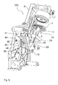
- FIG. 5 shows a further embodiment of the invention.
- the link 5 on the side walls 2 stops 40 namely an angled in the plane of the side wall 2 extending upper edge 44 and an equally shaped lower edge 46.
- the start edges 44, 46 are in the plane the side walls 2 offset from each other and formed staggered parallel to the plane of the side walls 2 of the height. They are thus stepped in the direction of displacement of the brewing piston 3 stepped one above the other. They go into a common outer surface 48, which is perpendicular to the respective side wall 2 and run down in a run-on slope 50.
- control wings 24 run against the chamfers 50 and can be pushed away from them by the side walls 2 inwards.
- the control vanes 24 slide only over the lower start edges 46 (at a more than regular pomace) or over the two start edges 44, 46 and jump back to its starting position towards the side wall 2 to the outside. In FIG. 5 they rest against the upper starting edges 44.
- the control wing 24 fixed. The rotatable mounting of the control lever 17 yet allows him to be moved down together with the brewing cylinder.
- the upper leading edge 44 deflects the control wing 24 and thus rotates the control lever 17.
- the control wing 24 slides along the upper edge 44 along until it comes free at a rotation of about 90 ° and in this position on the outer surfaces 48th strips downwards.
Abstract
Description
Die Erfindung betrifft eine Brühgruppe für einen Kaffeevollautomaten und insbesondere eine Brühgruppe mit einem Brühzylinder, einem im Brühzylinder verschiebbar gelagerten Brühkolben, dessen Oberseite eine Tresterfläche beim Brühvorgang definiert, einer mit dem Brühkolben gekoppelten Kolbenstange bzw. Stößel als dessen Antrieb und einem Steuerhebel für den Antrieb der Kolbenstange.The invention relates to a brewing group for a coffee machine and in particular a brewing group with a brewing cylinder, a brewing cylinder slidably mounted in the brewing cylinder whose top defines a pomace during brewing, coupled to the brewing piston rod or plunger as its drive and a control lever for driving the piston rod.
Bei herkömmlichen Kaffeevollautomaten für den Hausgebrauch werden gewöhnlicherweise Brühgruppen mit einem in einem Brühzylinder verschiebbar gelagerten Brühkolben verwendet, der über eine Kolbenstange mit einem durch einen Antrieb in Bewegung gesetzten Steuerhebel in Verbindung steht. Die Bewegung des Steuerhebels dient sowohl dem Verpressen des Kaffeepulvers als auch dem Ausstoßen des ausgelaugten Kaffeepulvers bzw. Tresters aus der Brühkammer.In conventional home-use automatic coffee makers, brewing groups are usually used with a brewing piston displaceably mounted in a brewing cylinder, which is connected via a piston rod to a control lever set in motion by a drive. The movement of the control lever serves both the pressing of the coffee powder and the ejection of the leached coffee powder or pomace from the brewing chamber.
Die
Der Brühkolben ist für den Tresterauswurf sowohl in Zug- als auch in Druckrichtung mit der Brühgruppe weitgehend kinematisch gekoppelt. Um auch unterschiedliche Pulver- bzw. Trestervolumina auswerfen zu können, ohne zu verklemmen, hält der Brühkolben einen Sicherheitsabstand gegenüber dem Brühkammeroberteil ein. Damit können auch unplanmäßig große Volumina verpresst und ausgestoßen werden.The brewing piston is largely kinematically coupled with the brewing group for the pulp ejection in both the tension and compression directions. In order to obtain different powder or to be able to eject pomace volumes without jamming, the brewing piston maintains a safe distance from the top part of the brewing chamber. This also unpredictably large volumes can be pressed and ejected.
Aufgabe der Erfindung ist es, einen Kaffeevollautomaten anzugeben, bei dem ein vollständiger Ausstoß des Tresters unabhängig von seinem Volumen gewährleistet ist.The object of the invention is to provide a fully automatic coffee machine, in which a complete output of the pomace is guaranteed regardless of its volume.
Diese Aufgabe wird erfindungsgemäß bei einer Brühgruppe eines Kaffeevollautomaten der eingangs genannten Art mit einer Brühgruppe für einen Kaffeevollautomaten mit den im Anspruch 1 angegebenen Merkmalen bzw. mit einem Kaffeevollautomaten gemäß Anspruch 10 erreicht.This object is achieved according to the invention in a brewing group of a coffee machine of the type mentioned with a brewing group for a coffee machine with the features specified in claim 1 or with a coffee machine according to claim 10.
Demnach wird die Aufgabe durch ein in Antriebsrichtung des Brühkolbens elastisches Element zwischen dem Antrieb des Steuerhebels und des Brühkolbens bzw. seiner Tresterfläche gelöst. Das elastische Element kann also an nahezu jedem Ort innerhalb einer kinematischen Kette aus dem Steuerhebel, der Kolbenstange bis hin zum Brühkolben selbst und dort noch unterhalb der Tresterfläche angebracht sein. Die Antriebsrichtung des Brühkolbens muss nicht identisch mit seiner Bewegungsrichtung sein, sondern entspricht einer der ggf. unterschiedlichen Bewegungsrichtungen eines am Antrieb des Brühkolbens beteiligten Bestandteils der Brühgruppe, beispielsweise des schwenkbaren Steuerhebels. Die Erfindung wendet sich also davon ab, zum Ausgleich von Toleranzen in der Kaffeepulvermenge einen planmäßigen Leerlauf zum Antrieb des Steuerhebels vorzusehen. Sie verfolgt vielmehr das Prinzip eines planmäßig elastischen Ausgleichs in der kinematischen Kette im Antrieb des Brühkolbens.Accordingly, the object is achieved by an elastic in the drive direction of the brewing element between the drive of the control lever and the brewing piston or its pomace. The elastic element can therefore be mounted at almost any location within a kinematic chain from the control lever, the piston rod to the brewing piston itself and there even below the grave surface. The drive direction of the brewing piston does not have to be identical to its direction of movement, but corresponds to one of the possibly different directions of movement of a component of the brewing group involved in the drive of the brewing piston, for example the pivotable control lever. The invention thus turns away from providing a scheduled idle for driving the control lever to compensate for tolerances in the coffee powder quantity. Rather, it pursues the principle of a planned elastic compensation in the kinematic chain in the drive of the brewing piston.
Als elastisches Element kann jedes Bauteil dienen, das bei einer Druck- oder Zugbeanspruchung eine elastische Rückstellkraft aufbaut. Der Fachmann kennt elastische Elemente, deren Elastizität auf Formelastizität, Materialelastizität oder Kombinationen daraus beruht, bei denen die Rückstellkraft zum Beispiel auf einer mechanischen Federkraft oder auf Materialeigenschaften beruht. Die Stärke der Rückstellkraft lässt sich durch eine Formgebung des elastischen Elements oder eine Materialauswahl für das elastische Element abstimmen. Zum Beispiel über die Federkonstante eines Federelements oder die Shore-Härte eines Elastomers lässt sie sich derart abstimmen, dass eine weitgehend definierte Kraft auf den Brühkolben einwirkt, um so eine weitgehend definierte Verdichtung des Tresters im Brühzylinder zu ermöglichen. Eine definierte Verdichtung des Tresters nach dem Brühvorgang sorgt für eine optimale Feuchtigkeit bzw. eine gewünschte Trockenheit des Tresters, so dass er vollständig und rückstandsfrei aus der Brühkammer ausgestoßen werden kann.As an elastic element can serve any component that builds up a resilient restoring force in a compressive or tensile stress. The person skilled in the art knows elastic elements whose elasticity is based on elasticity of the shape, material elasticity or combinations thereof in which the restoring force is based, for example, on a mechanical spring force or on material properties. The strength of the restoring force can be adjusted by a shaping of the elastic element or a material selection for the elastic element. For example, via the spring constant of a spring element or the Shore hardness of an elastomer, it can be tuned such that a largely defined force acts on the brewing piston, so as to allow a largely defined compaction of the pomace in the brewing cylinder. A defined compression of the pomace after the brewing process ensures optimum moisture or a desired dryness of the pomace, so that it can be completely and without residue expelled from the brewing chamber.
Falls das Volumen des gemahlenen Kaffeepulvers zum Beispiel auf Grund der Bohnenqualität oder des Mahlgrades größer ist als üblich, ist bei gleich bleibendem Antriebsweg des Steuerhebels der auf einen starren Brühkolben ausgeübte Druck herkömmlicherweise größer als vorgegeben. Das erfindungsgemäß eingesetzte elastische Element kann diesen erhöhten Druck ausgleichen, indem es dem erhöhten Druck teilweise nachgibt und sich so weit komprimieren oder expandieren lässt, dass nahezu der vorgesehene Verpressdruck für die definierte Verdichtung sorgt. Dadurch kann bei gleich bleibendem Antriebsweg des Steuerhebels der Verschiebeweg des Brühkolbens reduziert oder vergrößert und damit das Volumen der Brühkammer geringfügig vergrößert bzw. verkleinert werden. Dadurch wirkt auch auf das vergrößerte Trestervolumen eine weitgehend gleiche Verpresskraft wie auf ein planmäßiges Trestervolumen.If the volume of the ground coffee powder is greater than usual, for example due to the quality of the beans or the degree of grinding, the pressure exerted on a rigid brewing piston is usually greater than predetermined given the same drive path of the control lever. The elastic element used according to the invention can compensate for this increased pressure by partially yielding to the increased pressure and allowing it to compress or expand to such an extent that almost the envisaged compression pressure ensures the defined compression. As a result, with the drive path of the control lever remaining the same, the displacement path of the brewing piston can be reduced or increased and thus the volume of the brewing chamber can be slightly increased or reduced. As a result, a largely equal pressing force acts on the increased volume of pomace as well as on a scheduled pomace volume.
Umgekehrtes gilt, falls das Volumen des Tresters geringer als planmäßig ausfällt und der voreingestellte Weg des Brühkolbens nicht ausreicht, um den für eine gleich bleibende Qualität erforderlichen Verpressdruck im Trester zu erzielen. In diesem Falle kann das elastische Element das Volumen der Brühkammer etwas verringern. Denn mit Aufbringen der planmäßigen Verpresskraft auf den Brühkolben wird das elastische Element planmäßig komprimiert oder expandiert (z.B. eine Zugfeder). Ist der Antriebsweg des Steuerhebels ausgeschöpft, ohne einen planmäßigen Verpressdruck im Trester hervorzurufen, aktiviert das elastische Element seine Rückstellkraft. Sie addiert sich zur Verpresskraft des Steuerhebels, so dass auf den Trester weitgehend die vorgesehene Verpresskraft einwirkt. Vorgesehene bzw. planmäßige Verpresskraft heißt im Sinne der Erfindung, dass die mittels des Brühkolbens auf die Oberfläche des Tresters ausgeübte Kraft sich in einem bestimmten Toleranzbereich einstellt. Je nach Rückstellkraft des elastischen Elements, zum Beispiel der Rückstellkraft eines Federelements oder des Elastizitätsmoduls eines elastischen Materials, kann so eine planmäßige Verpresskraft auf den Trester und damit dessen ausreichender Verdichtungsgrad eingestellt werden.Conversely, if the volume of the pomace is lower than planned and the preset path of the brewing piston is not sufficient to achieve the required pressure for a consistent quality in the pomace. In this case, the elastic element can reduce the volume of the brewing chamber somewhat. Because with application of the scheduled pressing force on the brewing piston, the elastic element is compressed or expanded according to plan (eg a tension spring). If the drive travel of the control lever is exhausted without causing a systematic pressure in the pomace, the elastic element activates its restoring force. It adds to the pressing force of the control lever, so that largely acts on the pomace the intended pressing force. Foreseen or scheduled pressing force in the sense of the invention means that the force exerted on the surface of the pomace by means of the brewing piston is set within a certain tolerance range. Depending on the restoring force of the elastic element, for example the restoring force of a spring element or the modulus of elasticity of an elastic material, a systematic pressing force on the marc and thus its sufficient degree of compaction can be set.
Der Steuerhebel steuert die Bewegungen des Brühkolbens in vorbestimmten Bewegungsmustern. "Vorbestimmte Bewegungsmuster" im Sinne der Erfindung heißt, dass der Steuerhebel Bewegungsabläufe des Brühkolbens definiert. Regelmäßige Bewegungen des Brühkolbens sind eine translatorische Schiebebewegung innerhalb des Brühzylinders und - zusammen mit dem Brühzylinder - eine rotatorische Kippbewegung in Richtung eines Auffangbehälters oder eines Kaffeepulvereinfüllstutzens. Die Bewegungen können durch eine Führung des Brühkolbens zum Beispiel in Schienen oder Drehlagerungen gesteuert werden. Ein beispielhafter Ablauf solcher Bewegungsabfolgen in einer Kulissenführung ist in der Patentanmeldung
In einer ersten vorteilhaften Ausgestaltung der erfindungsgemäßen Brühgruppe umfasst die Kolbenstange selbst das elastische Element. Dabei kann entweder die gesamte Kolbenstange oder nur ein Teilbereich der Kolbenstange elastisch ausgestaltet sein. Es kann jedes elastische Material eingesetzt werden, das unter den Brühbedingungen stabil ist oder das vom Brühbereich derart abgeschirmt ist, dass es nicht den hohen Temperaturen und der hohen Luftfeuchtigkeit, die gewöhnlich im Brühbereich vorliegen, ausgesetzt ist. Elastische Materialien können zum Beispiel Elastomere aus Kunststoffen oder elastische Kautschukmaterialien sein. Das elastische Element befindet sich jedenfalls in der Kolbenstange in einem Bereich zwischen dem Angriffspunkt des Steuerhebels an der Kolbenstange und der Koppelung der Kolbenstange am Brühkolben. Alternativ dazu kann das elastische Element in einer Belastungsrichtung an der Kolbenstange befestigt sein und bei einer Belastung der Kolbenstange komprimiert werden. Zum Beispiel kann die Kolbenstange aus wenigstens zwei teleskopierbaren Bauteilen ausgestaltet sein, die miteinander über eine Schraubenfeder elastisch verbunden sind. Dadurch lässt sich das elastische Element besonders Platz sparend in der Brühgruppe unterbringen.In a first advantageous embodiment of the brewing group according to the invention, the piston rod itself comprises the elastic element. In this case, either the entire piston rod or only a portion of the piston rod can be designed to be elastic. Any elastic material that is stable under the brewing conditions or that is shielded from the brewing area such that it is not exposed to the high temperatures and high humidity that are usually present in the brewing area can be used. Elastic materials may be, for example, elastomers of plastics or elastic rubber materials. The elastic element is located in any case in the piston rod in an area between the point of application of the control lever on the piston rod and the coupling of the piston rod to the brewing piston. Alternatively, the elastic member may be fixed to the piston rod in a loading direction and compressed at a load of the piston rod. For example, the piston rod can be configured from at least two telescoping components, which are elastically connected to each other via a coil spring. As a result, the elastic element can be accommodated in a space-saving manner in the brewing group.
Nach einer weiteren vorteilhaften Ausgestaltung der erfindungsgemäßen Brühgruppe kann die Kolbenstange mit einem ihrer Enden, also am Brühkolben oder ihrem dem Brühkolben entgegengesetzten Ende, in einer Hülse geführt bzw. gehalten und das elastische Element in der Hülse angeordnet sein. Die Hülse kann also an einer kinematischen Koppelungsstelle der Kolbenstange angreifen, an der der Steuerhebel die Verpresskraft einleitet oder die Kolbenstange die Verpresskraft an den Brühkolben weitergibt. Das elastische Element kann dabei die Kolbenstange in der Hülse elastisch federnd lagern. Die Hülse samt elastischem Element kann bei Verschleiß einfach ausgetauscht oder gegebenenfalls nachgerüstet werden, so dass auch ältere Kaffeevollautomaten erfinderisch ausgestaltet werden können.According to a further advantageous embodiment of the brewing group according to the invention, the piston rod with one of its ends, ie at the brewing piston or its end opposite the brewing piston, guided in a sleeve and held and the elastic element can be arranged in the sleeve. The sleeve can therefore act on a kinematic coupling point of the piston rod, at which the control lever initiates the pressing force or the piston rod transmits the pressing force to the brewing piston. The elastic element can elastic the piston rod in the sleeve store resilient. The sleeve together with elastic element can easily be replaced when worn or optionally retrofitted, so that even older coffee machines can be designed in an innovative way.
In einer weiteren vorteilhaften Ausgestaltung kann das elastische Element an oder in dem Steuerhebel vorgesehen sein. Da das elastische Element dann etwas weiter von dem Brühkolben entfernt liegt, wird es weniger durch Temperatur- und Feuchtigkeitsschwankungen beaufschlagt als ein direkt an der Kolbenstange vorgesehenes Element. Alternativ kann das elastische Element direkt am Verbindungsbereich zwischen dem Steuerhebel und dem Brühkolben bzw. am Anfang der Bewegungskette, d. h. unmittelbar am Kraftübergang vom Antrieb auf den Steuerhebel, ausgebildet sein. So muss kein weiteres bewegliches Bauteil eingesetzt werden, was den Verschleiß reduziert und die Lebensdauer der Brühgruppe erhöht.In a further advantageous embodiment, the elastic element may be provided on or in the control lever. Since the elastic element is then slightly further away from the brewing piston, it is less affected by temperature and humidity fluctuations than an element provided directly on the piston rod. Alternatively, the elastic element can be directly connected to the connection area between the control lever and the brewing piston or at the beginning of the movement chain, d. H. be formed directly on the power transfer from the drive to the control lever. So no further moving component must be used, which reduces wear and increases the life of the brew group.
Nach einer weiteren vorteilhaften Ausführungsform der Erfindung kann das elastische Element eine Feder, zum Beispiel eine Spiralfeder oder eine Blattfeder, sein. Sie sind regelmäßig aus Metall und daher robust und verschleißarm ausgebildet. Spiralfedern oder Blattfedern können zum Beispiel in einer Hülse unterhalb der Kolbenstange angebracht sein, um die Rückstellkraft auf die Kolbenstange in Richtung des Brühkolbens auszuüben. Alternativ kann eine Spiralfeder zum Beispiel auch in einem Bereich der Kolbenstange selbst vorgesehen sein, zum Beispiel innerhalb der oben genannten teleskopierbaren Kolbenstange. Alternativ können zwei Hebelarme des Steuerhebels, die zueinander verschwenkbar sind, über z. B. eine Spiralfeder als elastisches Element gegeneinander abgestützt sein. Auch hier kann es sich bei der Spiralfeder um eine Druck - oder eine Zugfeder handeln.According to a further advantageous embodiment of the invention, the elastic element may be a spring, for example a spiral spring or a leaf spring. They are regularly made of metal and therefore robust and wear-resistant. Coil springs or leaf springs may for example be mounted in a sleeve below the piston rod to exert the restoring force on the piston rod in the direction of the brewing piston. Alternatively, a coil spring may for example also be provided in a region of the piston rod itself, for example within the above-mentioned telescoping piston rod. Alternatively, two lever arms of the control lever, which are pivotable to each other, z. B. a coil spring may be supported as an elastic element against each other. Again, it may be at the coil spring to a pressure or a tension spring.
In einer weiteren erfindungsgemäßen Ausgestaltung kann der Steuerhebel einen abgewinkelten Hebelarm umfassen, der ganz oder teilweise aus einem elastischen Material ausgebildet ist. Er kann zugleich als Befestigungselement zur Verbindung des Steuerhebels mit der Kolbenstange dienen. Ein abgewinkelter Hebelarm aus einem hinreichend flexiblen Material kann zum Beispiel ganz oder teilweise aus einem Metalldraht oder einem flexiblen Kunststoffbügel ausgebildet sein, der beim Bewegen der Kolbenstange eine ausreichende Rückstellkraft auf die Kolbenstange beim Verdichten des Tresters ausüben kann. Die Abwinkelung ermöglicht eine definierte Biegung des Metalldrahts proportional zu einer aufgebrachten Kraft. Damit ist die Kolbenstange so gelagert, dass sie beim Verdichten des Tresters etwas nachgeben kann. Da der Steuerhebel zugleich das elastische Element enthält, er also eine Doppelfunktion übernimmt, führt diese Ausgestaltungsform zu einer besonders Platz sparenden Konstruktion. Ein elastisch ausgebildeter Steuerhebel, mit dem die Kolbenstange geführt ist, ist auch weniger störanfällig, zum Beispiel hinsichtlich Verklemmungen bzw. Überlastungen des Brühkolbens auf Grund von Volumentoleranzen des Tresters, da der Steuerhebel bei Überlastung etwas nachgeben kann. Ein erfindungsgemäß ausgebildeter Steuerhebel kann zudem einfach ausgetauscht und nachgerüstet werden, ohne dass dazu weitere Baugruppen verändert werden müssen.In a further embodiment of the invention, the control lever may comprise an angled lever arm, which is formed wholly or partly of an elastic material. He can also serve as a fastener for connecting the control lever to the piston rod. An angled lever arm of a sufficiently flexible material may for example be wholly or partly formed of a metal wire or a flexible plastic strap, which can exert a sufficient restoring force on the piston rod during compression of the pomace when moving the piston rod. The bend allows a defined bend of the Metal wire proportional to an applied force. Thus, the piston rod is stored so that it can yield slightly when compacting the pomace. Since the control lever also contains the elastic element, so he assumes a dual function, this embodiment leads to a particularly space-saving design. An elastically formed control lever, with which the piston rod is guided, is also less susceptible to interference, for example with regard to jamming or overloading of the brewing piston due to volume tolerances of the pomace, since the control lever can yield slightly in case of overloading. An inventively designed control lever can also be easily replaced and retrofitted, without the need for further modules to be changed.
In einer weiteren vorteilhaften Ausgestaltung der Erfindung kann ein elastisches Element im Brühbetrieb weitgehend unabhängig von dem in den Brühzylinder eingefüllten Kaffeevolumen eine weitgehend definierte Verpresskraft über den Brühkolben auf den in dem Brühzylinder befindlichen Trester ausüben. Der Vorteil der definierten Druckkraft liegt in der bereits geschilderten definierten Verdichtung des Tresters. Da ja erfindungsgemäß der Verdichtungsgrad weitgehend definierbar und konstant ist, kann eine vollständige Entleerung der Brühkammer sichergestellt werden, auch wenn das Volumen des gemahlenen Kaffeepulvers variiert.In a further advantageous embodiment of the invention, an elastic element in the brewing operation largely independently of the filled into the brewing cylinder coffee volume exert a largely defined pressing force on the brewing piston on the pomace in the brewing cylinder. The advantage of the defined compressive force lies in the already described defined compaction of the pomace. Since according to the invention the degree of compaction is largely definable and constant, a complete emptying of the brewing chamber can be ensured, even if the volume of the ground coffee powder varies.
Allen Ausführungsformen ist gemeinsam, dass eine größere Verarbeitungsbandbreite bezüglich des eingesetzten Kaffeepulvers möglich ist. Insbesondere eine Variation der Kaffeepulvermenge kann durch die erfindungsgemäße Ausgestaltung der Brühgruppe verarbeitet werden. Das führt dazu, dass der Trester mit einer weitgehend definierten Kraft verpresst wird, so dass Qualitätsschwankungen des erhaltenen Produkts, d. h. der aufgebrühten Kaffeeportionen, durch Tresterrückstände aus vorangegangenen Zubereitungsvorgängen ausgeschlossen werden können. Dies wird auch erzielt, ohne dass zum Beispiel auf Schwankungen in der Kaffeequalität oder betriebsbedingte Funktionstoleranzen oder Abnützungen des Kaffeevollautomaten, insbesondere des eingebauten Mahlwerks, geachtet werden muss. Da der Anpressdruck des Brühkolbens auf den Trester nach dem Brühvorgang durch die Elastizität des Federelements weitgehend definiert ist, kommt es zu einem rückstandfreien Auswurf des Tresters.All embodiments have in common that a greater processing bandwidth with respect to the coffee powder used is possible. In particular, a variation of the coffee powder quantity can be processed by the inventive design of the brewing group. The result of this is that the pomace is compressed with a largely defined force, so that fluctuations in quality of the product obtained, ie the brewed portions of coffee, can be excluded by residue of the residue from previous preparation operations. This is also achieved, for example, without having to pay attention to fluctuations in the quality of coffee or operational functional tolerances or wear of the coffee machine, in particular the built-in grinder. Since the contact pressure of the brewing piston on the pomace after the brewing process is largely defined by the elasticity of the spring element, there is a residue-free ejection of the pomace.
Die aus dem Stand der Technik bekannten Kniehebel-Brühgruppen verfügen über eine Kulisse im Brühgruppengehäuse zur Steuerung insbesondre auch des Steuerhebels. Nach einer weiteren vorteilhaften Ausgestaltung der Erfindung kann die Kulisse Auslenkmittel umfassen, die eine trestervolumen-abhängige Auslenkung des Steuerhebels ermöglichen. Die Auslenkmittel erlauben es, die Auslenkbewegung des Steuerhebels in Abhängigkeit von der Größe des Trestervolumens sofort und ohne Einhalten von Sicherheitsabständen auszulösen. Die Auslenkmittel machen eine Auslenkung des Steuerhebels und damit die Verschubbewegung des Brühkolbens zum Auswurf des Tresters von dessen Volumen insofern abhängig, als eine große Trestermenge eine andere Verpressbewegung des Brühkolbens auslöst als eine kleine. Damit gelingt es, mit einfachen mechanischen Mitteln eine weitgehend gleichartige Verpressung des Tresters unabhängig von seinem Volumen zu erreichen und ihn zuverlässig und vollständig auszuwerfen. Vor allem geringere als planmäßige Trestervolumina lassen sich erfindungsgemäß ausreichend verpressen, dadurch entwässern und vollständig auswerfen. Erfindungsgemäße Auslenkmittel können gestaffelt angeordnete Anlaufkanten, Rasten oder Reibflächen an der Kulisse sein, die auf die Steuerflügel des Steuerhebels wirken. Weitere Ausführungsformen dazu finden sich in der Anmeldung mit dem Anmelderzeichen 201101587 und dem Titel "Vorrichtung zur volumenabhängigen Tresterverpressung" vom selben Tag wie die vorliegende Anmeldung.Known from the prior art toggle lever groups have a backdrop in Brühgruppengehäuse to control insbesondre also the control lever. According to a further advantageous embodiment of the invention, the backdrop may comprise deflection means which allow a volume-dependent displacement of the control lever. The deflection means make it possible to trigger the deflection movement of the control lever as a function of the size of the pomace volume immediately and without observing safety distances. The deflection means make a deflection of the control lever and thus the shifting movement of the brewing piston for ejecting the pomace of its volume dependent insofar as a large amount of pomace another compression movement of the brewing piston triggers as a small. This makes it possible with simple mechanical means to achieve a substantially similar compression of the pomace regardless of its volume and eject it reliably and completely. Above all, lower than scheduled pomace volumes can be sufficiently compressed according to the invention, thereby dehydrate and completely eject. Inventive deflection means may be staggered arranged start edges, notches or friction surfaces on the backdrop, which act on the control wing of the control lever. Further embodiments thereof can be found in the application with the applicant's mark 201101587 and the title "device for volume-dependent pulp pressing" from the same day as the present application.
Die vorstehenden, erfindungsgemäß ausgestalteten Brühgruppen können vorteilhafterweise in einem Kaffeevollautomaten, wie zum Beispiel einer Kaffeemaschine für den Hausgebrauch, eingesetzt werden. Die eingangs genannte Aufgabe wird daher auch durch einen Kaffeevollautomaten mit einer erfindungsgemäßen Brühgruppe der vorgenannten Art gelöst.The above, inventively designed Brühgruppen can advantageously be used in a coffee machine, such as a coffee machine for household use. The aforementioned object is therefore also achieved by a coffee machine with a brewing group according to the invention of the aforementioned type.
Das Prinzip der Erfindung wird im Folgenden anhand von Zeichnungen beispielshalber noch näher erläutert. In den Zeichnungen zeigen:
- Figur 1:
- eine perspektivische Vorderseitenansicht einer ersten Ausführungsform einer erfindungsgemäßen Brühgruppe,
- Figur 2:
- eine perspektivische Rückseitenansicht der Brühgruppe,
Figuren 3, 4:- perspektivische Ansichten eines Steuerhebels gemäß einer zweiten Ausführungsform der Erfindung, und
- Figur 5:
- eine perspektivische Ansicht einer dritten Ausführungsform einer erfindungsgemäßen Brühgruppe.
- FIG. 1:
- a perspective front view of a first embodiment of a brewing group according to the invention,
- FIG. 2:
- a perspective rear view of the brewing group,
- FIGS. 3, 4:
- perspective views of a control lever according to a second embodiment of the invention, and
- FIG. 5:
- a perspective view of a third embodiment of a brewing group according to the invention.
In den
Die Brühgruppe umfasst des Weiteren einen Brühzylinder (nicht gezeigt), in dem der Brühkolben 4 verschiebbar angeordnet ist und der zusammen mit einem Brühkammeroberteil eine Brühkammer (beide nicht gezeigt) ausbildet. In der Brühkammer wird gemahlenes Kaffeepulver durch den Brühkolben 4 verpresst und anschließend ausgelaugt. Der Brühkolben 4 verdichtet den verbleibenden Trester nach dem Auslaugen ein weiteres Mal und stößt ihn aus der Brühkammer aus. Diese Bewegungen des Brühkolbens 4 werden über eine Kulissenführung 5 in den Wänden 2 mit Hilfe der Steuerflügel 24 des Steuerhebels 17 bestimmt. Die Kulissenführung 5 definiert über Führungsschienen und Anschlagpunkte die Bewegungsabläufe des Steuerhebels 17. Erfindungsgemäß werden die vorhandenen Anschlagpunkte und Bewegungsabläufe weitgehend unverändert verwendet, wobei jedoch das elastische Element 18 in der Hülse 19 Toleranzen im Trestervolumen zulässt.The brewing group further comprises a brewing cylinder (not shown) in which the
Die becherförmige Hülse 19 mit ihrem rechteckigen Boden 191 (
Der Brühkolben 4 ist über die Kolbenstange 3 mit dem Steuerhebel 17 gekoppelt und wird durch sie in dem Brühzylinder auf und ab bewegt. Bei unveränderten Bewegungsabläufen ermöglicht das elastische Element 18 eine Vergrößerung des Brühkammervolumens, falls das Trestervolumen zum Beispiel aufgrund eines gröberen Mahlgrads größer als das erwartete Volumen ist. Es erlaubt dem Brühkolben 4, während des Verdichtens des Tresters einen größeren als den planmäßigen Abstand zum Brühkammeroberteil einzuhalten, obwohl der Steuerhebel 17 die vorgesehene Position für ein vollständiges Verpressen des Tresters eingenommen hat. Denn das größere Volumen in der Brühkammer gleicht das elastische Element 18 durch seine Kompression aus. Damit kann der Steuerhebel 17 seine planmäßige Endposition einnehmen, ohne das größere Trestervolumen übermäßig zu verpressen oder gar den Brühkolben 4 zu verklemmen. Der Steuerhebel 17 bringt vielmehr einen weitgehend planmäßigen, nämlich geringfügig höheren Verpressdruck auf den Trester auf. Die Endposition muss im Vergleich zu einer herkömmlichen Brühgruppe nicht verändert werden, da das elastische Element 18 einen geringeren Verschiebeweg des Brühkolbens und damit die Variation des Brühkammervolumens in der erfindungsgemäßen Brühgruppe ermöglicht.The
Die Elastizität des elastischen Elements 18 ist derart bemessen, dass eine Belastung durch den Steuerhebel 17 das elastische Element 18 jedenfalls komprimiert. Falls nun das Trestervolumen geringer als planmäßig ist, erreicht der Brühkolben 4 beim Verpressvorgang seine Endposition, noch bevor ein ausreichender Verspressdruck auf das Trestervolumen wirkt. Jetzt kann das elastische Element 18 mangels ausreichendem Verpressdruck als Gegenkraft seine Rückstellkraft aktivieren, drückt den Brühkolben 4 etwas weiter in Richtung des Brühkolbenoberteils (nicht gezeigt) und verkleinert damit das Brühlkammervolumen. Die Verkleinerung erfolgt so lange, bis der Druck weitgehend, nämlich nicht ganz dem definierten Verpressdruck entspricht bzw. bis der Trester weitgehend den planmäßigen Verdichtungsgrad erreicht hat, der für eine rückstandfreie Entleerung der Brühkammer zweckmäßig ist.The elasticity of the
In der
Ein zu großes Volumen des Tresters in der Brühkammer ruft bei seiner Verdichtung einen Gegendruck hervor. Bislang wurde der Trester dadurch stärker als geplant verpresst. Jetzt nimmt das elastische Element 18' durch Kompression einen wesentlichen Teil der Energie des Gegendrucks auf den Steuerarm 20 auf. Dadurch wird verhindert, dass der Brühkolben 4 einen übermäßigen Verpressdruck auf den Trester ausübt, was eine weitgehend definierte Verdichtung des Tresters bewirkt.Too large a volume of the pomace in the brewing chamber causes a back pressure during its compression. So far the pomace has been pressed harder than planned. Now, the elastic member 18 'receives by compression a substantial part of the energy of the back pressure on the
Auch das elastische Element 18' ist derart bemessen, dass es bei einer Belastung des Steuerhebels 17' beim Verdichten des Tresters jedenfalls komprimiert wird. Befindet sich in der Brühkammer ein geringeres als das planmäßige Kaffeepulvervolumen, das nach Erreichen der Endposition des Brühkolbens 4 noch nicht ausreichend verpresst ist, aktiviert das elastische Element 18' seine Rückstellkraft. Es sorgt damit für eine ausreichende Verdichtung auch des geringeren Trestervolumens.Also, the elastic element 18 'is dimensioned such that it is compressed in any case at a load of the control lever 17' during compaction of the pomace. Located in the brewing chamber is less than the planned coffee powder volume, which is not sufficiently compressed after reaching the end position of the
Somit kann mit dem elastischen Steuerhebel 17' von Kaffeeportion zu Kaffeeportion eine gleich bleibende Qualität gewährleistet werden. Der Steuerhebel 17' kann in eine herkömmliche Brühgruppen eingesetzt bzw. gegen einen herkömmlichen Steuerhebel 17 ausgetauscht werden, ohne dass die Brühgruppe im Übrigen geändert werden müsste.Thus, with the elastic control lever 17 'of coffee portion to coffee portion a consistent quality can be ensured. The control lever 17 'can be used in a conventional brewing groups or exchanged for a
Bei einer Aufwärtsbewegung des Brühzylinders und des Steuerhebels 17 laufen die Steuerflügel 24 gegen die Anlaufschrägen 50 an und lassen sich von ihnen von den Seitenwänden 2 weg nach innen drücken. Je nach Befüllungsgrad der Brühkammer bzw. je nach Trestervolumen gleiten die Steuerflügel 24 nur über die unteren Anlaufkanten 46 (bei einer mehr als planmäßigen Trestermenge) oder über die beiden Anlaufkanten 44, 46 hinweg und springen zurück in seine Ausgangsstellung Richtung Seitenwand 2 nach außen. In
Da es sich bei den vorhergehenden, detailliert beschriebenen Brühgruppen um Ausführungsbeispiele handelt, können sie in üblicher Weise vom Fachmann in einem weiten Umfang modifiziert werden, ohne den Bereich der Erfindung zu verlassen. Insbesondere können die konkreten Ausgestaltungen der elastischen Elemente in anderer Form als in der hier beschriebenen vorliegen. Ebenso kann der Brühzylinder oder der Steuerhebel in einer anderen Form ausgestaltet werden, wenn dies aus Platzgründen bzw. designerischen Gründen notwendig ist. Weiterhin schließt die Verwendung der unbestimmten Artikel "ein" bzw. "eine" nicht aus, dass die betreffenden Merkmale auch mehrfach vorhanden sein können. Auch die Verwendung der Bezeichnungen "Mittel", "System" und "Element" schließt nicht aus, dass ein solches Bauteil aus mehreren Komponenten aufgebaut ist.Since the preceding groups of brews described in detail are exemplary embodiments, they can be modified in a customary manner by a person skilled in the art to a large extent, without departing from the scope of the invention. In particular, the concrete embodiments of the elastic elements in other Form as present in the described here. Likewise, the brewing cylinder or the control lever can be configured in another form, if this is necessary for reasons of space or designerischen reasons. Furthermore, the use of the indefinite article "on" or "one" does not exclude that the characteristics in question may also be present multiple times. Also, the use of the terms "medium", "system" and "element" does not exclude that such a component is made up of several components.
- 22
- Wandwall
- 33
- Kolbenstangepiston rod
- 44
- Brühkolbenbrewing plunger
- 55
- Kulissenführunglink guide
- 1111
- DurchtrittsöffnungenThrough openings
- 1212
- Tresterflächemarc area
- 17, 17'17, 17 '
- Steuerhebelcontrol lever
- 18, 18'18, 18 '
- elastisches Elementelastic element
- 1919
- Hülseshell
- 2020
- Steuerarmcontrol arm
- 2121
- Lagerbolzenbearing bolt
- 2222
- Langlöcherslots
- 2323
- WiderlagerhöckerAbutment humps
- 2424
- Steuerflügelcontrol wing
- 3131
- oberes Endetop end
- 3232
- unteres Endelower end
- 4040
- Auslenkmitteldeflecting
- 4444
- obere Anlaufkanteupper leading edge
- 4646
- untere Anlaufkantelower starting edge
- 4848
- Außenflächeouter surface
- 5050
- Anlaufschrägestarting slope
- 100100
- Brühgruppengehäusebrewing unit
- 191191
- Bodenground
- 192192
- Becherrandcup edge
- 193193
- Zapfenspigot
Claims (10)
Applications Claiming Priority (1)
| Application Number | Priority Date | Filing Date | Title |
|---|---|---|---|
| DE201110082436 DE102011082436A1 (en) | 2011-09-09 | 2011-09-09 | Elastic pomace crimping |
Publications (1)
| Publication Number | Publication Date |
|---|---|
| EP2567645A1 true EP2567645A1 (en) | 2013-03-13 |
Family
ID=46796427
Family Applications (1)
| Application Number | Title | Priority Date | Filing Date |
|---|---|---|---|
| EP12182652A Ceased EP2567645A1 (en) | 2011-09-09 | 2012-08-31 | Elastic marc pressing |
Country Status (2)
| Country | Link |
|---|---|
| EP (1) | EP2567645A1 (en) |
| DE (1) | DE102011082436A1 (en) |
Cited By (4)
| Publication number | Priority date | Publication date | Assignee | Title |
|---|---|---|---|---|
| EP3669716A1 (en) * | 2018-12-17 | 2020-06-24 | Jura Elektroapparate AG | Brewing device for coffee machines and coffee machine with brewing device |
| WO2021217961A1 (en) * | 2020-04-30 | 2021-11-04 | 苏州咖乐美咖啡机科技有限公司 | Elastic assembly and top residue reset assembly for beverage brewing apparatus, and apparatus thereof |
| DE102020117378A1 (en) | 2020-07-01 | 2022-01-05 | Eugster/Frismag Ag | Spring-loaded brewing unit and method for operating a spring-loaded brewing unit |
| DE102020125447B3 (en) | 2020-09-29 | 2022-02-03 | Eugster/Frismag Ag | Brewing unit for a beverage preparation device, beverage preparation device and method for operating a brewing unit |
Families Citing this family (1)
| Publication number | Priority date | Publication date | Assignee | Title |
|---|---|---|---|---|
| DE102017209053A1 (en) * | 2017-05-30 | 2018-12-06 | BSH Hausgeräte GmbH | Coffee machine, in particular coffee machine |
Citations (4)
| Publication number | Priority date | Publication date | Assignee | Title |
|---|---|---|---|---|
| EP0202517A1 (en) * | 1985-05-07 | 1986-11-26 | IN ALBON, Jean-Paul | Automatic coffee maker |
| EP1552777A1 (en) * | 2004-01-09 | 2005-07-13 | RANCILIO MACCHINE PER CAFFE' S.p.A. | Piston for a beverage infusion automatic machine |
| DE202009000258U1 (en) | 2009-01-09 | 2009-03-26 | BSH Bosch und Siemens Hausgeräte GmbH | Brewing group with largely constant powder compaction |
| DE102007060813A1 (en) | 2007-12-18 | 2009-06-25 | BSH Bosch und Siemens Hausgeräte GmbH | Automatic coffee machine, for espresso coffee, has a cylinder with a sliding piston with a perforated curved surface and a closing piston |
-
2011
- 2011-09-09 DE DE201110082436 patent/DE102011082436A1/en not_active Withdrawn
-
2012
- 2012-08-31 EP EP12182652A patent/EP2567645A1/en not_active Ceased
Patent Citations (4)
| Publication number | Priority date | Publication date | Assignee | Title |
|---|---|---|---|---|
| EP0202517A1 (en) * | 1985-05-07 | 1986-11-26 | IN ALBON, Jean-Paul | Automatic coffee maker |
| EP1552777A1 (en) * | 2004-01-09 | 2005-07-13 | RANCILIO MACCHINE PER CAFFE' S.p.A. | Piston for a beverage infusion automatic machine |
| DE102007060813A1 (en) | 2007-12-18 | 2009-06-25 | BSH Bosch und Siemens Hausgeräte GmbH | Automatic coffee machine, for espresso coffee, has a cylinder with a sliding piston with a perforated curved surface and a closing piston |
| DE202009000258U1 (en) | 2009-01-09 | 2009-03-26 | BSH Bosch und Siemens Hausgeräte GmbH | Brewing group with largely constant powder compaction |
Cited By (5)
| Publication number | Priority date | Publication date | Assignee | Title |
|---|---|---|---|---|
| EP3669716A1 (en) * | 2018-12-17 | 2020-06-24 | Jura Elektroapparate AG | Brewing device for coffee machines and coffee machine with brewing device |
| WO2021217961A1 (en) * | 2020-04-30 | 2021-11-04 | 苏州咖乐美咖啡机科技有限公司 | Elastic assembly and top residue reset assembly for beverage brewing apparatus, and apparatus thereof |
| DE102020117378A1 (en) | 2020-07-01 | 2022-01-05 | Eugster/Frismag Ag | Spring-loaded brewing unit and method for operating a spring-loaded brewing unit |
| EP3932268A1 (en) | 2020-07-01 | 2022-01-05 | Eugster/Frismag AG | Suspended brewing unit and method for operating a suspended brewing unit |
| DE102020125447B3 (en) | 2020-09-29 | 2022-02-03 | Eugster/Frismag Ag | Brewing unit for a beverage preparation device, beverage preparation device and method for operating a brewing unit |
Also Published As
| Publication number | Publication date |
|---|---|
| DE102011082436A1 (en) | 2013-03-14 |
Similar Documents
| Publication | Publication Date | Title |
|---|---|---|
| EP2055214B1 (en) | Brewing device for a coffee machine | |
| DE3607656C2 (en) | ||
| EP2567645A1 (en) | Elastic marc pressing | |
| WO2007017455A1 (en) | Apparatus for extracting an extraction substance, which is contained in a capsule, with a liquid extraction means | |
| EP2030537B1 (en) | Brewing device for a coffee machine | |
| EP1912542A1 (en) | Apparatus for extracting an extraction substance, which is contained in a capsule, with a liquid extraction means | |
| EP2629648B1 (en) | Brewing device and coffee machine having a brewing device | |
| EP2036466A1 (en) | Brewing device for a coffee machine | |
| EP2451324B1 (en) | Brewing unit, in particular for a coffee maker | |
| EP3902745A1 (en) | Coffee grinder having filling device for refillable coffee capsules | |
| DE202009000258U1 (en) | Brewing group with largely constant powder compaction | |
| EP2654524B1 (en) | Automatic coffee machine with spindle drive | |
| EP2244617A1 (en) | Brewing unit for a coffee maker | |
| DE102013202148A1 (en) | Coffee machine with spindle brewing unit | |
| WO2018210899A1 (en) | Brewing module and beverage-preparing machine | |
| DE60007022T2 (en) | Machine for preparing espresso coffee with hydraulic device for compacting the ground coffee | |
| EP1535554A1 (en) | Extractiondevice of coffee for a coffee machine | |
| AT406820B (en) | COFFEE MACHINE | |
| WO2016079672A1 (en) | Brewing head for an espresso machine | |
| EP2567644B1 (en) | Device for volume-independent marc pressing | |
| EP2036467A1 (en) | Percolator for preparing hot drinks | |
| DE2703327C3 (en) | Forming device for banderoles for a thermoforming machine for the production of thermoplastic containers | |
| DE202016103124U1 (en) | The beverage maker | |
| DE102013202151A1 (en) | Coffee machine with spindle brewing unit | |
| EP3932268B1 (en) | Suspended brewing unit and method for operating a suspended brewing unit |
Legal Events
| Date | Code | Title | Description |
|---|---|---|---|
| PUAI | Public reference made under article 153(3) epc to a published international application that has entered the european phase |
Free format text: ORIGINAL CODE: 0009012 |
|
| AK | Designated contracting states |
Kind code of ref document: A1 Designated state(s): AL AT BE BG CH CY CZ DE DK EE ES FI FR GB GR HR HU IE IS IT LI LT LU LV MC MK MT NL NO PL PT RO RS SE SI SK SM TR |
|
| AX | Request for extension of the european patent |
Extension state: BA ME |
|
| 17P | Request for examination filed |
Effective date: 20130913 |
|
| RBV | Designated contracting states (corrected) |
Designated state(s): AL AT BE BG CH CY CZ DE DK EE ES FI FR GB GR HR HU IE IS IT LI LT LU LV MC MK MT NL NO PL PT RO RS SE SI SK SM TR |
|
| 17Q | First examination report despatched |
Effective date: 20150209 |
|
| RAP1 | Party data changed (applicant data changed or rights of an application transferred) |
Owner name: BSH HAUSGERAETE GMBH |
|
| STAA | Information on the status of an ep patent application or granted ep patent |
Free format text: STATUS: THE APPLICATION HAS BEEN REFUSED |
|
| 18R | Application refused |
Effective date: 20160709 |