EP2567643A1 - Basis für einen teekocher, steuerverfahren dafür und teekocher - Google Patents
Basis für einen teekocher, steuerverfahren dafür und teekocher Download PDFInfo
- Publication number
- EP2567643A1 EP2567643A1 EP11835509A EP11835509A EP2567643A1 EP 2567643 A1 EP2567643 A1 EP 2567643A1 EP 11835509 A EP11835509 A EP 11835509A EP 11835509 A EP11835509 A EP 11835509A EP 2567643 A1 EP2567643 A1 EP 2567643A1
- Authority
- EP
- European Patent Office
- Prior art keywords
- turntable
- tea
- cup
- tea machine
- machine base
- Prior art date
- Legal status (The legal status is an assumption and is not a legal conclusion. Google has not performed a legal analysis and makes no representation as to the accuracy of the status listed.)
- Granted
Links
Images


Classifications
-
- A—HUMAN NECESSITIES
- A47—FURNITURE; DOMESTIC ARTICLES OR APPLIANCES; COFFEE MILLS; SPICE MILLS; SUCTION CLEANERS IN GENERAL
- A47J—KITCHEN EQUIPMENT; COFFEE MILLS; SPICE MILLS; APPARATUS FOR MAKING BEVERAGES
- A47J31/00—Apparatus for making beverages
- A47J31/44—Parts or details or accessories of beverage-making apparatus
- A47J31/4403—Constructional details
- A47J31/441—Warming devices or supports for beverage containers
- A47J31/4425—Supports for beverage containers when filled or while being filled
Definitions
- the present invention relates to a tea machine, and more particular to a tea machine base and its control method thereof, especially for the tea machine with the tea machine base thereof.
- a conventional tea machine base generally comprises a base body, a dripping tray, and a grid panel, wherein the dripping tray and the grid panel are coupled at the base body.
- the grid panel is positioned above the dripping tray. Accordingly, a tea pot and tea cups are placed on the grid panel for the use of brewing tea. During the brewing process, the water dripped out from the tea cups and/or the tea pot will be collected by the dripping tray through the grid panel.
- the conventional tea machine base does not provide multiple functions and is considered as a low end apparatus. Therefore, there is a need for the tea machine base to provide multiple functions and to significant upgrade the quality of the tea machine base in the market.
- the invention is advantageous in that it provides a tea machine base and its control method thereof, which provides multiple functions and significant upgrades the quality of the tea machine base.
- another advantage of the invention is to provide a tea machine base which is adapted to automatically detect whether any tea cup is placed on the tea machine base.
- another advantage of the invention is to provide a tea machine which is adapted for automatically filling water and discharging water.
- a tea machine base of a tea machine which comprises an electric motor, a turntable, and a supporting shaft, wherein a supporting platform is formed at the top side of the supporting shaft.
- a bottom side of the supporting shaft is upwardly extended from a bottom side of the tea machine base.
- the turntable is coaxially coupled at the supporting shaft.
- the turntable further comprise at least two cup holders formed thereon in a radial direction and a plurality of positioning contact terminals, wherein the number of cup holders matches with the number of positioning contact terminals.
- a positioning switch is provided at the supporting platform corresponding to the positioning contact terminal. The turntable is driven to rotate by the electric motor.
- the operational configuration of the present invention is that when the electric motor is activated to drive the turntable to rotate, the tea cup on the cup holder will be driven to move correspondingly.
- the positioning contact terminal is moved to alignedly contact with the positioning switch in order to stop the rotation of the turntable so as to move the tea cup at a desired position. Therefore, when the tea machine incorporates with the tea machine base, the tea machine can automatically dispense the brewed tea to the tea cup in a corrected alignment.
- the tea machine can be supported on the supporting platform for dispensing the brewed tea from the tea machine to the tea cup on the tea machine base.
- the turntable is rotatable and the supporting platform is stationary.
- the turntable is driven to rotate by the electric motor by a belt transmission unit, a gear transmission unit, or a chain transmission unit.
- the belt transmission unit comprises a driven gear, a driving gear and a driving belt having a V-shaped cross section.
- the driven gear is coaxially coupled at the supporting shaft, wherein a top side of the driven gear is coupled with the turntable.
- the driving gear is operatively coupled at an output shaft of the electric motor.
- the gear transmission unit transmits the output power by the transmission gears at same planar direction (involute gear transmission).
- the chain transmission unit transmits the output power via an endless roller chain.
- the tea machine base further comprises a supporting base, wherein the bottom side of the supporting shaft is upwardly extended from the supporting base.
- a ball bearing is provided between the driven gear and the supporting base.
- an axle bearing is provided between the driven gear and the supporting shaft.
- the axle bearing is provided between the contact surfaces between the driven gear and the supporting shaft.
- the tea machine base further comprises a tea cup which comprises a permanent magnet provided at the bottom side of the tea cup.
- a magnetic switch which is preferably an electromagnetic switch, is provided at each of the cup holders, wherein two first terminal heads are extended from the magnetic switch to a surrounding sidewall of the turntable.
- a plurality of second terminal heads are provided at the surrounding sidewall of the supporting platform to match and contact with the first terminal heads.
- the cup holding bases are formed on the top side of the turntable, wherein the cup holders are supported at the cup holding bases respectively.
- the turntable further comprise a supporting post upwardly extended from the cup holding base, a pivot arm pivotally coupled at the supporting post, and an actuating member movably supported at the cup holder, wherein one end of the pivot arm is contacted with and supported underneath the actuating member to define an actuating end, and an opposed end of the pivot arm provided with a magnetic element, such as magnet, to form a magnetic end.
- the pivot point of the actuating member defines two ends of the actuating member as the actuating end and the magnetic end respectively, wherein the weight of the magnetic end of the pivot arm is heavier than the actuating end thereof.
- the turntable further comprises a sensor switch provided at the supporting platform.
- the actuating member is movably supported at the cup holder at a center thereof.
- the cup holding bases are formed on the top side of the turntable, wherein the cup holders are supported at the cup holding bases respectively.
- the turntable further comprises a movable post downwardly extended from the cup holder.
- the turntable further comprises a guiding member which is downwardly extended from the cup holding base.
- a resilient element is supported between the guiding member and the cup holding base. The upper end of the guiding member contacts with the bottom end of the movable post.
- the turntable further comprises a sensor unit supported thereunder for detecting a downward movement of the guiding member.
- the sensor unit comprises a signal transmission unit.
- the sensor unit comprises a touch switch.
- the turntable further comprises a guiding seat supported underneath the cup holding base, wherein the guiding member is coaxially and slidably extended through the guiding seat, wherein the resilient element is disposed in the guiding seat.
- the present invention comprises a tea machine base, which comprises an electric motor, a turntable, a securing base having a U-shaped cross section.
- the output shaft of the electric motor is coupled at a center of the turntable.
- the turntable comprises at least two cup holders provided on the top side of the turntable, and a plurality of positioning contact terminals, wherein the number of positioning contact terminal matches with the number of cup holders.
- the turntable further comprises a positioning switch provided at the securing base to align with the positioning contact terminal.
- the turntable further comprises a supporting handle extended around an outer side of the surrounding wall of the cup holder and a supporting block extended from an inner side of the surrounding wall of the securing base, wherein the supporting handle is supported on the supporting block.
- the tea machine base further comprises at least a tea cup which comprises a permanent magnet provided at the bottom side of the tea cup.
- a magnetic switch which is an electromagnetic switch, is provided at the securing base.
- the present invention comprises a tea machine with a tea machine base, wherein the tea machine comprises a base support, a water boiling container, a water tank, a tea basket, a tea infusing container, and a tea dispensing outlet.
- the tea machine base comprises an electric motor, a turntable, and a securing base, wherein a supporting platform is formed at the top side of the supporting shaft. A bottom side of the supporting shaft is upwardly extended from a bottom side of the tea machine base.
- the turntable is coaxially coupled at the supporting shaft.
- the turntable further comprise at least two cup holders formed thereon in a radial direction and a plurality of positioning contact terminals, wherein the number of cup holders matches with the number of positioning contact terminals.
- a positioning switch is provided at the supporting platform corresponding to the positioning contact terminal.
- the turntable is driven to rotate by the electric motor.
- the tea machine is supported on the supporting platform, wherein the water dispensing outlet is provided at the bottom of the tea infusing container and is aligned with the cup holder for dispensing brewed tea from the tea infusing container to the tea cup when the tea cup is placed on the cup holder.
- the present invention comprises a tea machine with a tea machine base, wherein the tea machine comprises a base support, a water boiling container, a water tank, a tea basket, a tea infusing container, and a tea dispensing outlet.
- the tea machine base comprises an electric motor, a turntable, and a securing base, wherein a center the turntable is coupled at the output shaft of the electric motor.
- the tea machine is supported on the supporting platform at the peripheral portion thereof, wherein the water dispensing outlet is provided at the bottom of the tea infusing container and is aligned with the cup holder for dispensing brewed tea from the tea infusing container to the tea cup when the tea cup is placed on the cup holder.
- the present invention comprises a method of controllably dispensing the brewed tea by the tea machine, which the following steps.
- the turntable is driven to initially rotate via the control circuit.
- the control circuit will determine whether the tea cup is placed on the cup holder or not.
- the tea cup is placed on the cup holder, the brewed tea will be automatically dispensed to the tea cup.
- the tea machine will be controlled for stop dispensing the brewed tea to the detected tea cup via the execution signal of the control circuit.
- the turntable is driven to rotate again at one direction for dispensing the brewed tea to the next detected tea cup.
- the tea machine will verify whether the brewing process is completed or not.
- control circuit will verify whether the turntable is rotated at one full revolution for verifying all positions of the cup holders. If the turntable is not rotated at one full revolution, the turntable is kept rotating until the turntable is stopped at one full revolution.
- the counter of the control circuit will record the activation number of the positioning switch in order to determine whether the turntable is rotated at one full revolution.
- the present invention provides the electric motor to drive the turntable to rotate, wherein the rotational movement of the turntable is controlled by the relatively positions between the positioning contact terminals and the positioning switch, so as to control the turntable to rotate or to stop rotating.
- the turntable is fully automated to provide multiple functions and significant upgrades the quality of the tea machine base.
- the control circuit will verify the position of the tea cup, will control the rotation of the turntable, and will controllably dispense the brewed tea to the tea cup on the turntable, so as to enhance the automated functions of dispensing brewed tea to the tea cup and filling up water in the tea machine.
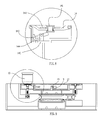
- Fig. 1 is a sectional view of a tea machine base of a tea machine according to a first model of the present invention.
- Fig. 2 is a sectional view of an electromagnetic switch structure of the tea machine according to the above first model of the present invention.
- Fig. 3 is a sectional view of a guiding rib structure of the tea machine according to the above first model of the present invention.
- Fig. 4 is a partially sectional view of a tea cup of the tea machine according to the above first model of the present invention.
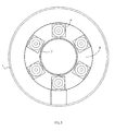
- Fig. 5 is a top view of the tea machine base of the tea machine according to the above first model of the present invention.
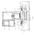
- Fig. 6 is a sectional view of the tea machine with the tea machine base according to the above first model of the present invention.
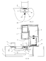
- Fig. 7 is a sectional view of a tea machine base of a tea machine according to a second model of the present invention.
- Fig. 8 is a sectional view of a tea cup detection of the tea machine base according to the second model of the present invention.
- Fig. 9 is a sectional view of a tea machine base of a tea machine according to a third model of the present invention.
- Fig. 10 is a sectional view of a tea cup detection of the tea machine base according to the third model of the present invention.
- Fig. 11 is a sectional view of a tea machine base of a tea machine according to a fourth model of the present invention.
- Fig. 12 is a sectional view of a tea cup detection of the tea machine base according to the fourth model of the present invention.
- Fig. 13 is a sectional view of a tea machine base of a tea machine according to a fifth model of the present invention.
- Fig. 14 is a sectional view of a tea machine base of a tea machine according to a sixth model of the present invention.
- Fig. 15 is a sectional view of a tea machine base of a tea machine according to a seventh model of the present invention.
- a tea machine base of a tea machine according to a first embodiment of the present invention is illustrated, wherein the tea machine base comprises an outer casing 1, a supporting base 2 supported within the outer casing 1, an electric motor 6 disposed in the outer casing 1, a water reservoir 7 at a bottom side of the outer casing 1, a turntable 10, a supporting shaft 16, and a control circuit.
- the supporting base 2 is supported on the bottom side of the outer casing 1 (or the supporting base 2 can be integrated with the outer casing 1 at the bottom side thereof), wherein a top side of the supporting base 2 is extended above a top side of the water reservoir 7. In other words, height of the supporting base 2 is larger than the depth of the water reservoir 7.
- the bottom side of the supporting shaft 16 is coaxially and securely extended from the supporting base 2, wherein a supporting platform 17 is formed at the top side of the supporting shaft 16.
- the turntable 10 is coaxially and rotatably coupled at the supporting shaft 16.
- the turntable 10 comprises a plurality of cup holders 14 and a plurality of corresponding contact terminals 19, preferably six cup holders and six contact terminals, wherein a positioning switch 9 is provided at the supporting platform 17 corresponding to the positioning contact terminal 19.
- the water reservoir 7 is provided at the bottom side of the outer casing 1, wherein a plurality of water outlets 21, preferably four water outlets, are formed at the supporting base 2 to communicate with the water reservoir 7.
- the turntable 10 is driven to rotate about the supporting shaft 6 by the electric motor 6.
- the turntable 10 is driven to rotate by the electric motor 6 by a belt transmission unit.
- the belt transmission unit comprises a driven gear 3, a driving gear 4 and a driving belt 5 having a V-shaped cross section.
- the driven gear 3 is coaxially coupled at the supporting shaft 16, wherein a top side of the driven gear 3 is coupled with the turntable 10.
- the driving gear 4 is operatively coupled at an output shaft of the electric motor 6.
- a ball bearing 8 is provided between the driven gear 3 and the supporting base 2. (Since the position of the supporting base 2 is higher the position of the water reservoir 7, the ball bearing 8 at the supporting shaft 16 will not contact with the water in the water reservoir 7.)
- An axle bearing 161 is provided between the driven gear 3 and the supporting shaft 16.
- axle bearing 161 is provided between the contact surfaces between the driven gear 3 and the supporting shaft 16. Therefore, the friction between the driven gear 3 and the supporting base 2, and the friction between the driven gear 3 and the supporting shaft 16 will be substantially reduced via the ball bearing 8 and the axle bearing 161 respectively so as to effectively enhance the power efficiency of the electric motor 6 and to enhance the stably of the power transmission through the belt transmission unit.
- the turntable 10 is driven to rotate by the electric motor 6 by a gear transmission unit or a chain transmission unit.
- a gear transmission unit or a chain transmission unit In order to drive the turntable 10 to rotate, two transmission gears are operatively coupled to the output shaft of the electric motor 6 and the turntable 10 respectively, wherein the transmission gears are engaged with each other to transmit the output power from the electric motor 6 to the turntable 10.
- the turntable 10 further comprise a plurality of cup holding bases 145 integrally formed on the top side of the turntable 10, wherein the cup holders 14 are supported at the cup holding bases 145 respectively.
- a magnetic switch 13, which is preferably an electromagnetic switch, is provided at each of the cup holders 14, wherein two first terminal heads 11 are extended from the magnetic switch 13 to a surrounding sidewall of the respective cup holding base 145.
- a plurality of second terminal heads 12 are provided at the surrounding sidewall of the supporting platform 17 to match and contact with the first terminal heads 11, wherein the second terminal heads 12 are operatively linked to the control circuit.
- the turntable 10 further has a water collecting chamber 20 provided therein and a plurality of water exits 18, preferably eight water exits.
- a water passage is formed at the cup holding base 145 to communicate with the water collecting chamber 20. Therefore, the water within the cup holding base 145 will be guided to and collected by the water collecting chamber 20. In addition, after the water is collected in the water collecting chamber 20, the water will be guided to and collected by the water reservoir 7 through the water exits 18 and the water outlets 21.
- the supporting shaft 16 comprises at least a guiding rib 162 integrally, radially, and outwardly protruded from an upper portion of the supporting shaft 16 and at least a guiding channel 163 formed at the supporting shaft 16 above the guiding rib 162. Accordingly, when the water leaks through the gap, the water will be guided to flow to the water reservoir 7 through the guiding channel 163.
- the guiding rib 162 is extended at an inclined angle from the supporting shaft 16 at a position right above the guiding channel 163 to prevent the water accumulated at the guiding rib 162 and to ensure the water being guided to the guiding channel 163. It is worth mentioning that if the water leaks to the axle bearing 161, the axle bearing 161 will be corrupted.
- the tea machine base further comprises at least a tea cup 15 which comprises a permanent magnet 151 provided at the bottom side of the tea cup 15.
- the cup holder 14 further comprises a magnetic member 142, such as an armature, provided thereat corresponding to the permanent magnet 151 of the tea cup 15 when the tea cup 15 is supported on the cup holder 14.
- the permanent magnet 151 of the tea cup 15 is magnetically attracted to the magnetic member 142 of the cup holder 14 when the tea cup 15 is supported on the cup holder 14 so as to prevent the tea cup 15 being flipped over by the centrifugal force when the turntable 10 is rotated.
- the control circuit will determine the tea cup 15 being supported at the cup holder 14.
- the tea machine base further comprises a tea cup detection to determine whether there is the tea cup 15 seated thereon or not. The tea machine base will also determine how many tea cups 15 being seated thereon as well.
- the permanent magnet 151 of the tea cup 15 is magnetically attracted to the magnetic member 142 of the cup holder 14, so as to retain the tea cup 15 in position. Therefore, the tea cup 15 will not be unintentionally moved or accidentally flipped over or dropped off the cup holder 14 when the turntable 10 is rotated.
- the permanent magnet 151 of the tea cup 15 will also activate the magnetic switch 13 at the cup holder 14 via the magnet field of the permanent magnet 151.
- the electric motor 6 is automatically activated to drive the driving gear 4 to rotate. Then, the driving belt 5 will transmit the rotational power from the driving gear 4 to the driven gear 3 so as to drive the driven gear 3 to rotate. The rotational movement of the driven gear 3 will drive the turntable 10 to rotate.
- the control circuit will deactivate the electric motor 6, such that the turntable 10 will stop rotating. At the same time, the first terminal heads 11 are aligned and contacted with the second terminal heads 12.
- the magnetic switch 13 will send a signal to the control circuit such that the control circuit will confirm the tea cup 15 being placed on the respective cup holder 14.
- the output power of the electric motor 6 can transmit to the turntable 10 through the belt transmission unit.
- the belt transmission unit can be replaced by either the gear transmission unit which transmits the output power by the transmission gears at same planar direction or at 3-dimensional directions, or the chain transmission unit.
- the mechanism of the transmission units can be easily configured to effectively transmit the output power.
- the above mentioned tea machine base is incorporated in the tea machine which forms a fully automated tea machine for automatically filling water and dispensing brewed tea.
- the tea machine further comprises a base support 28, a water boiling container 29, a water tank 30, a tea basket 31, a tea infusing container 32, and a tea dispensing outlet 33.
- the base support 28 is securely supported on the supporting platform 17.
- the water dispensing outlet 33 is provided at the bottom of the tea infusing container 32 and is aligned with the cup holder 14 for dispensing brewed tea from the tea infusing container 32 to the tea cup 15 when the tea cup 15 is placed on the cup holder 14.
- the structural configuration of the tea machine is disclosed in China Patent Application No. 201010256065.4, filed August 17,2010 .
- the control circuit will determine whether the brewing process of the brewed tea in the tea infusing container 3 is completed.
- the control circuit will determine whether the tea cup 15 is placed on the cup holder 14 or not via the magnetic switch 13. When the magnetic switch 13 is activated, the control circuit will confirm the tea cup 15 being placed on the respective cup holder 14. The control circuit will stop the rotation of the turntable 10. If the magnetic switch 13 is not activated, the control circuit will confirm that no the tea cup 15 is placed on the respective cup holder 14. Therefore, the turntable 10 will be kept rotating.
- the tea dispensing outlet 33 is controllably actuated for dispensing the brewed tea in the tea infusing container 32 to the detected tea cup 15 via the execution signal of the control circuit. After the preset dispensing time, the dispensing outlet 33 is controllably closed for stop dispensing the brewed tea to the detected tea cup 15 via the execution signal of the control circuit. After the dispensing process is completed, the turntable 10 is driven to rotate again at one direction for dispensing the brewed tea to the next detected tea cup 15.
- the control circuit will verify whether the turntable 10 is rotated at one full revolution for verifying all positions of the cup holders 14. If the turntable 10 is not rotated at one full revolution, the turntable 10 is controllably rotated at one direction and is stopped at one full revolution. For example, when there is six positioning contact terminal 19, the control circuit will count the positioning switch 9 contacting with the six positioning contact terminal 19. After counting to the sixth time, the turntable 10 will be rotated at one full revolution and will be stopped. The electric motor 6 is then deactivated and the counter of the control circuit will be initialized as zero.
- the turntable 10 being kept rotating refers to the turntable 10 being rotated at the same direction.
- a tea machine according to a third embodiment illustrates an alternative mode of the above first embodiment, which has a different tea cup detection to determine whether there is any tea cup 15 on the cup holder 14.
- the cup holding bases 145 are formed on the top side of the turntable 10, wherein the cup holders 14 are supported at the cup holding bases 145 respectively.
- the turntable 10 further comprise a supporting post 148 upwardly extended from the cup holding base 145, a pivot arm 143 pivotally coupled at the supporting post 148, and an actuating member 141 movably supported at the cup holder 14, wherein one end of the pivot arm 143 is contacted with and supported underneath the actuating member 141 to define an actuating end, and an opposed end of the pivot arm 143 provided with a magnetic element, such as magnet, to form a magnetic end.
- the weight of the magnetic end of the pivot arm 143 is heavier than the actuating end thereof.
- the turntable 10 further comprises a sensor switch 22 provided at the supporting platform 17, preferably at the surrounding wall thereof.
- a sensor switch 22 provided at the supporting platform 17, preferably at the surrounding wall thereof.
- the actuating member 141 movably supported at the cup holder 14 at a center thereof.
- the actuating member 141 When the tea cup 15 is place on the cup holder 14, the actuating member 141 is moved down to push the actuating end of the actuating member 141 downwardly, such that the magnetic end of the pivot arm 143 is pivotally lifted up to align with the sensor switch 22 so as to activate the sensor switch 22. Accordingly, the pivot arm 143 is pivotally moved at a horizontal position to activate the sensor switch 22. Therefore, the control circuit will confirm there is the tea cup 15 on the cup holder 14. When the tea cup 15 is removed from the cup holder 14, the magnetic end of the actuating member 141 is automatically dropped down by its own weight.
- a resilient element such as a compression spring, can be supported at the actuating member 141, preferably underneath the actuating end thereof, in order to apply the upward force to the actuating end of the actuating member 141 if the magnetic end thereof is not heavy enough.
- a tea machine according to a fourth embodiment illustrates an alternative mode of the above third embodiment, wherein the tea machine of the fourth embodiment includes all components of the third embodiment expect the tea cup detection to determine whether there is any tea cup 15 on the cup holder 14.
- the cup holding bases 145 are formed on the top side of the turntable 10, wherein the cup holders 14 are supported at the cup holding bases 145 respectively.
- the turntable 10 further comprises a movable post 141 downwardly extended from the cup holder 14, preferably at the center thereof.
- the turntable 10 further comprises a guiding seat 627, having a tubular structure, supported underneath the cup holding base 145, and a guiding member 620 which is downwardly extended from the cup holding base 145 and is coaxially and slidably extended through the guiding seat 627, such that the up-and-down sliding movement of the guiding member 620 is guided by the guiding seat 627.
- a resilient element 622 is disposed in the guiding seat 627 and is coaxially coupled with the guiding member 620 for applying an upward pushing force against the guiding member 620, so as to move the guiding member 620 back to its original position.
- the upper end of the guiding member 620 contacts with the bottom end of the movable post 141.
- the turntable 10 further comprises a sensor unit supported thereunder for detecting a downward movement of the guiding member 620, wherein the sensor unit comprises a signal transmission unit.
- the sensor unit comprises a signal transmitter 24, preferably an infrared transmitter, and a signal receiver 25, preferably an infrared receiver, communicatively linked to the signal transmitter 24.
- a second blocking member 623 is downwardly extended from the guiding member 620, wherein when the guiding member 620 is downwardly moved by the weight of the tea cup 15, the second blocking member 623 is driven to move downward and is positioned between the signal transmitter 24 and the signal receiver 25.
- a bearing 621 is provided between the upper end of the guiding member 620 and the bottom end of the movable post 141.
- the movable post 141 When the tea cup 15 is place on the cup holder 14, the movable post 141 is pushed downwardly to correspondingly drive the guiding member 620 moving downward. At the same time, the resilient element 622 is compressed.
- the second blocking member 623 is driven by the downward movement of the guiding member 620 to move downward and is positioned between the signal transmitter 24 and the signal receiver 25. Therefore, the signal transmission between the signal transmitter 24 and the signal receiver 25 is blocked by the second blocking member 623, wherein the signal receiver 25 will not receive any signal from the signal transmitter 24.
- the control circuit will receive signal from the signal receiver 25 and will confirm the tea cup 15 being placed on the respective cup holder 14. On the other hand, when the signal receiver 25 receives the signal from the signal transmitter 24, i.e. the signal is not blocked by the second blocking member 623, the control circuit will confirm there is no tea cup 15 being placed on the respective cup holder 14.
- a tea machine according to a fifth embodiment illustrates an alternative mode of the above fourth embodiment, wherein the tea machine of the fourth embodiment includes all components of the third embodiment expect the sensor unit to determine whether there is any tea cup 15 on the cup holder 14.
- the sensor unit comprises a touch switch 626, wherein when the guiding member 620 is driven to move downward, the guiding member 620 will contact with the touch switch 626 so as to activate the touch switch 626.
- the touch switch 626 can be selectively supported at different locations to contact with different portions of the guiding member 620. For example, the touch switch 626 can be contacted with the bottom side of the guiding member 620 or with the lateral side guiding member 620 when the guiding member 620 is moved downwardly.
- the movable post 141 is pushed downwardly to correspondingly drive the guiding member 620 moving downward.
- the resilient element 622 is compressed.
- the second blocking member 623 is driven by the downward movement of the guiding member 620 to move downward and is contacted with the touch switch 626.
- the control circuit will receive signal from the touch switch 626 and will confirm the tea cup 15 being placed on the respective cup holder 14.
- a tea machine base illustrates an alternative mode of the first embodiment, wherein the tea machine base comprises an outer casing 1, an electric motor 6 disposed in the outer casing 1, a water reservoir 7 at a bottom side of the outer casing 1, a turntable 10, a securing base 35 having a U-shaped cross section supported in the outer casing 1, and a control circuit.
- the turntable 10 is operatively coupled at the output shaft of the electric motor 6.
- the output shaft of the electric motor 6 is coupled at a center of the turntable 10.
- the turntable 10 comprises a plurality of cup holders 14, preferably six cup holders, provided on the top side of the turntable 10, and a plurality of positioning contact terminals 19, wherein the number of positioning contact terminal 19 matches with the number of cup holders 14.
- the turntable 10 further comprises a positioning switch 9 provided at the securing base 35 to align with the positioning contact terminal 19.
- the positioning contact terminals 19 are embodied as a plurality of first blocking members 23.
- the positioning switch 9 comprises a signal transmitter 24 and a signal receiver 25 supported at the securing base 35 respectively, wherein the operation of the first blocking members 23 with respect to the signal transmitter 24 and the signal receiver 25 is the same as it is mentioned above.
- the tea machine base further comprises at least a tea cup 15 which comprises a permanent magnet 151 provided at the bottom side of the tea cup 15.
- a magnetic switch 13 which is preferably an electromagnetic switch, is provided at the securing base 35.
- the turntable 10 further comprises a supporting handle 26 extended around an outer side of the surrounding wall of the cup holder 14 and a supporting block 27 extended from an inner side of the surrounding wall of the securing base 35, wherein the supporting handle 26 is supported on the supporting block 27 to prevent the tea cup 15 from being flipped over or tilted when the turntable 10 is rotated.
- the cup holder 14 can be made of magnetized stainless steel material to magnetically attract the permanent magnet 151 of the tea cup 15.
- the above mentioned tea machine base is incorporated in the tea machine which forms a fully automated tea machine for automatically filling water and dispensing brewed tea.
- the tea machine further comprises a water tank 30, a water boiling container 29, a tea basket 31, a tea infusing container 32, and a tea dispensing outlet 33.
- the water dispensing outlet 33 is provided at the bottom of the tea infusing container 32 and is aligned with the cup holder 14 for dispensing brewed tea from the tea infusing container 32 to the tea cup 15 when the tea cup 15 is placed on the cup holder 14.
- the structural configuration of the tea machine is disclosed in China Patent Application No. 201010256065.4, filed August 17, 2010 .
- the control circuit will determine whether the brewing process of the brewed tea in the tea infusing container 3 is completed.
- the control circuit will determine whether the tea cup 15 is placed on the cup holder 14 or not via the magnetic switch 13. When the magnetic switch 13 is activated, the control circuit will confirm the tea cup 15 being placed on the respective cup holder 14, so as to precede the following step. The control circuit will stop the rotation of the turntable 10. If the magnetic switch 13 is not activated, the control circuit will confirm that no the tea cup 15 is placed on the respective cup holder 14. Therefore, the turntable 10 will be kept rotating.
- the tea dispensing outlet 33 is controllably actuated for dispensing the brewed tea in the tea infusing container 32 to the detected tea cup 15 via the execution signal of the control circuit. After the preset dispensing time, the dispensing outlet 33 is controllably closed for stop dispensing the brewed tea to the detected tea cup 15 via the execution signal of the control circuit. After the dispensing process is completed, the turntable 10 is driven to rotate again at one direction for dispensing the brewed tea to the next detected tea cup 15.
- the control circuit will verify whether the turntable 10 is rotated at one full revolution for verifying all positions of the cup holders 14. If the turntable 10 is not rotated at one full revolution, the turntable 10 is controllably rotated at one direction and is stopped at one full revolution. For example, when there is six positioning contact terminal 19, the control circuit will count the positioning switch 9 contacting with the six positioning contact terminal 19. After counting to the sixth time, the turntable 10 will be rotated at one full revolution and will be stopped. The electric motor 6 is then deactivated and the counter of the control circuit will be initialized as zero.
- the turntable 10 being kept rotating refers to the turntable 10 being rotated at the same direction.
- a tea machine according to an eighth embodiment illustrates an alternative mode of the above sixth embodiment, wherein the tea machine of the eighth embodiment includes all components of the sixth embodiment expect the first blocking member 23 being replaced by a permanent magnet 151 and the positioning switch 9 being replaced by an electromagnetic switch 13 at the securing base 35.
- a tea machine according to a ninth embodiment illustrates an alternative mode of the above seventh embodiment, wherein the tea machine of the ninth embodiment includes all components of the seventh embodiment expect a plurality of electromagnetic switches 13, preferably six electromagnetic switches, being coupled at the cup holders 14, preferably six cup holders, respectively.
- the second terminal heads 12 are provided at the inner side of the securing bases 35 respectively and are operatively linked to the control circuit, wherein two first terminal heads 11 are extended from the magnetic switch 13 to contact with the second terminal heads 12.
Landscapes
- Physics & Mathematics (AREA)
- Thermal Sciences (AREA)
- Engineering & Computer Science (AREA)
- Food Science & Technology (AREA)
- Apparatus For Making Beverages (AREA)
- Tea And Coffee (AREA)
Applications Claiming Priority (2)
| Application Number | Priority Date | Filing Date | Title |
|---|---|---|---|
| CN201010527538XA CN102058320B (zh) | 2010-10-29 | 2010-10-29 | 茶机基座及其控制方法、茶机 |
| PCT/CN2011/074618 WO2012055235A1 (zh) | 2010-10-29 | 2011-05-25 | 茶机基座及其控制方法、茶机 |
Publications (3)
| Publication Number | Publication Date |
|---|---|
| EP2567643A1 true EP2567643A1 (de) | 2013-03-13 |
| EP2567643A4 EP2567643A4 (de) | 2013-07-10 |
| EP2567643B1 EP2567643B1 (de) | 2014-11-19 |
Family
ID=43993979
Family Applications (1)
| Application Number | Title | Priority Date | Filing Date |
|---|---|---|---|
| EP11835509.8A Active EP2567643B1 (de) | 2010-10-29 | 2011-05-25 | Basis für einen teekocher, steuerverfahren dafür und teekocher |
Country Status (4)
| Country | Link |
|---|---|
| US (1) | US20130059049A1 (de) |
| EP (1) | EP2567643B1 (de) |
| CN (1) | CN102058320B (de) |
| WO (1) | WO2012055235A1 (de) |
Families Citing this family (20)
| Publication number | Priority date | Publication date | Assignee | Title |
|---|---|---|---|---|
| CN102058320B (zh) * | 2010-10-29 | 2012-12-26 | 晶辉科技(深圳)有限公司 | 茶机基座及其控制方法、茶机 |
| CN102319023B (zh) * | 2011-06-13 | 2013-08-28 | 晶辉科技(深圳)有限公司 | 茶机基座 |
| CN102488453A (zh) * | 2011-11-28 | 2012-06-13 | 大连民族学院 | 一种饮水机 |
| CN102987921B (zh) * | 2012-12-14 | 2015-10-28 | 深圳市北鼎晶辉科技股份有限公司 | 茶机 |
| CN106308514B (zh) * | 2016-10-27 | 2019-02-12 | 重庆市亚特蓝电器有限责任公司 | 一种具有自动取水功能的饮水机 |
| CN106388610A (zh) * | 2016-11-18 | 2017-02-15 | 厦门大学嘉庚学院 | 一种转盘式自动沏茶机及其工作方法 |
| CN107309881B (zh) * | 2017-07-19 | 2020-11-17 | 安徽工程大学 | 一种自动泡茶机器人 |
| GB2565162A (en) * | 2017-07-27 | 2019-02-06 | Hongkong Tayayo Electrical Tech Co Limited | Automatic tea maker |
| CN107485295A (zh) * | 2017-07-31 | 2017-12-19 | 安徽工程大学 | 一种斟茶机器人 |
| CN107853992B (zh) * | 2017-12-05 | 2024-05-31 | 厦门大学嘉庚学院 | 一种可分茶的多功能自动泡茶机及其使用方法 |
| TWI681745B (zh) * | 2018-03-20 | 2020-01-11 | 迅智自動化科技股份有限公司 | 飲品調製設備 |
| US11337544B1 (en) * | 2018-04-19 | 2022-05-24 | Saint Anthony Industries LTD | Single brew system |
| CN108968692A (zh) * | 2018-08-31 | 2018-12-11 | 江苏浩宇电子科技有限公司 | 非搅拌式自动冲饮机 |
| CN109393976B (zh) * | 2018-12-12 | 2024-10-29 | 厦门乐斯亮科技有限公司 | 一种萃茶机 |
| CN109567406A (zh) * | 2018-12-29 | 2019-04-05 | 鸿达磁健康科技有限公司 | 磁悬浮茶几 |
| US11312611B2 (en) * | 2019-05-13 | 2022-04-26 | Lg Electronics Inc. | Hydrogen water generator |
| CN112790611B (zh) * | 2021-01-11 | 2025-06-03 | 昆山丰澜智能科技有限公司 | 一种全自动泡茶装置及其控制系统和控制方法 |
| CN112971529B (zh) * | 2021-03-03 | 2023-12-15 | 林斯文 | 一种自动洗杯泡茶机 |
| CN115153302A (zh) * | 2021-04-02 | 2022-10-11 | 深圳市北鼎科技有限公司 | 无线驱动咖啡杯托旋转的咖啡机 |
| WO2023101947A1 (en) * | 2021-12-03 | 2023-06-08 | Starbucks Corporation | Revolving beverage holder |
Family Cites Families (39)
| Publication number | Priority date | Publication date | Assignee | Title |
|---|---|---|---|---|
| US2787402A (en) * | 1952-04-16 | 1957-04-02 | Color Carousel Corp | Liquid proportioning and dispensing apparatus |
| US2951617A (en) * | 1956-03-14 | 1960-09-06 | Color Carousel Corp | Automatic paint pigment proportioning and dispensing machine |
| US3023790A (en) * | 1959-11-06 | 1962-03-06 | Zaruba Wenzel | Automatic self-serving brewer or dispenser for coffee or other fluid substances |
| US3364989A (en) * | 1965-09-28 | 1968-01-23 | Philco Ford Corp | Air conditioner |
| US3891171A (en) * | 1974-04-15 | 1975-06-24 | Gen Signal Corp | Multi-bowl supporting table |
| US3915207A (en) * | 1974-04-16 | 1975-10-28 | Food Systems Inc Entire | High-speed, automatic, powdered food and heated water dispenser |
| US4258759A (en) * | 1979-03-29 | 1981-03-31 | Achen John J | Turntable for colorant dispensers |
| FR2605206B3 (fr) * | 1986-10-17 | 1989-04-21 | Reneka Ind Sa | Detecteur selectif de presence pour le poste de remplissage d'une machine a cafe automatique |
| US4921149A (en) * | 1988-06-09 | 1990-05-01 | Remcor Products Company | Ice portion control for ice dispenser and method |
| US5645172A (en) * | 1995-08-31 | 1997-07-08 | Shantzis; Mark D. | Separated waste collection control for multistory building |
| KR0184167B1 (ko) * | 1995-10-31 | 1999-03-20 | 한규생 | 유아용 우유병의 자동급유장치 및 그 제어장치 |
| US6053359A (en) * | 1997-12-22 | 2000-04-25 | Mcdonald's Corporation | Automated beverage system |
| CN2326137Y (zh) * | 1998-02-27 | 1999-06-30 | 张宇 | 饮料机 |
| US7032232B2 (en) * | 1998-06-01 | 2006-04-18 | Microboards Technology, Llc | Memory storage disk handling system |
| US7047277B1 (en) * | 1998-10-12 | 2006-05-16 | Mercury Interactive Corporation | System and computer-implemented method for creating configuration files for web transaction tests |
| DE69908547D1 (de) * | 1999-03-17 | 2003-07-10 | Euromeccanica Srl | Vorrichtung zum Dosieren von Flüssigkeiten |
| CN2386537Y (zh) * | 1999-06-09 | 2000-07-05 | 四川长虹电器股份有限公司 | 机械打火装置 |
| EP1186881A4 (de) * | 2000-03-16 | 2006-04-19 | Fuji Photo Film Co Ltd | Messverfahren und vorrichtung mit verwendung der abgeschwächten totalreflektion |
| CN2411708Y (zh) * | 2000-04-03 | 2000-12-27 | 张鸿义 | 餐桌自动转盘 |
| JP2002360612A (ja) * | 2001-06-11 | 2002-12-17 | Morita Mfg Co Ltd | 医療用自動コップ給水装置 |
| US6457496B1 (en) * | 2001-07-10 | 2002-10-01 | Copower Technology Co., Ltd. | Liquid dispensing and metering system |
| CN2540858Y (zh) * | 2002-04-08 | 2003-03-26 | 纪佩民 | 一种自动出水茶具 |
| JP2004195048A (ja) * | 2002-12-20 | 2004-07-15 | Meister:Kk | ボトル詰茶飲料の製造機 |
| US7028726B2 (en) * | 2003-01-21 | 2006-04-18 | Fqubed | Rotary-drive dispenser |
| KR100668624B1 (ko) * | 2004-11-05 | 2007-01-12 | 윤영석 | 한약재의 엑기스 추출장치 |
| US7998669B2 (en) * | 2006-03-02 | 2011-08-16 | Monsanto Technology Llc | Automated contamination-free seed sampler and methods of sampling, testing and bulking seeds |
| DE102006060748B3 (de) * | 2006-12-21 | 2008-01-24 | BSH Bosch und Siemens Hausgeräte GmbH | Getränkeautomat mit Mehrtassenzubereitung |
| PT1946684E (pt) * | 2007-01-19 | 2012-04-27 | Nestec Sa | Máquina autónoma de distribuição de alimentos e bebidas |
| US20090229180A1 (en) * | 2008-03-13 | 2009-09-17 | Rich Christopher T | Plant stand with rotating trivet and saucer |
| CN100546527C (zh) * | 2008-07-28 | 2009-10-07 | 张超 | 泡茶器 |
| MX2011006069A (es) * | 2008-12-08 | 2011-06-24 | Enodis Corp | Controlador y metodo para controlar un sistema integrado para suministrar y batir/mezclar ingredientes de bebida. |
| FR2942052B1 (fr) * | 2009-02-12 | 2014-08-01 | Guillemot Corp | Mini-joystick a effet hall a detection d'appui, et dispositif de controle correspondant |
| CN201452889U (zh) * | 2009-07-02 | 2010-05-12 | 曲绍麟 | 一种泡茶机 |
| EP2278283A1 (de) * | 2009-07-23 | 2011-01-26 | Mettler-Toledo AG | Verfahren zur Temperaturkorrektur einer Kraftmessvorrichtung und Kraftmessvorrichtung |
| US8616249B2 (en) * | 2010-02-01 | 2013-12-31 | Island Oasis Frozen Cocktail Co., Inc. | Blender with feature for dispensing product by weight |
| CN101912230B (zh) * | 2010-08-17 | 2014-05-07 | 晶辉科技(深圳)有限公司 | 茶机 |
| CN102058320B (zh) * | 2010-10-29 | 2012-12-26 | 晶辉科技(深圳)有限公司 | 茶机基座及其控制方法、茶机 |
| CN201911905U (zh) * | 2010-10-29 | 2011-08-03 | 晶辉科技(深圳)有限公司 | 茶机基座及包含该基座的茶机 |
| CN102172309B (zh) * | 2011-03-09 | 2012-10-31 | 庄梅兰 | 一种用于自动控制的磁性茶杯 |
-
2010
- 2010-10-29 CN CN201010527538XA patent/CN102058320B/zh active Active
-
2011
- 2011-05-25 EP EP11835509.8A patent/EP2567643B1/de active Active
- 2011-05-25 US US13/697,005 patent/US20130059049A1/en not_active Abandoned
- 2011-05-25 WO PCT/CN2011/074618 patent/WO2012055235A1/zh not_active Ceased
Also Published As
| Publication number | Publication date |
|---|---|
| WO2012055235A1 (zh) | 2012-05-03 |
| CN102058320B (zh) | 2012-12-26 |
| CN102058320A (zh) | 2011-05-18 |
| EP2567643A4 (de) | 2013-07-10 |
| US20130059049A1 (en) | 2013-03-07 |
| EP2567643B1 (de) | 2014-11-19 |
Similar Documents
| Publication | Publication Date | Title |
|---|---|---|
| EP2567643B1 (de) | Basis für einen teekocher, steuerverfahren dafür und teekocher | |
| US10131528B2 (en) | Flavoring dispensing apparatus, system and method | |
| JP5763671B2 (ja) | 挽いたコーヒー豆を投入するための装置及びその装置を含むマシン | |
| AU2011216596B2 (en) | Coffee beverage system, coffee bean packaging cartridge for use with said system, method of preparing a beverage, method for brewing coffee, method of supplying coffee beans, cartridge for coffee bean material, method of supplying coffee bean material | |
| CN110060419B (zh) | 咖啡胶囊售卖机 | |
| CN111615351A (zh) | 具有咖啡豆容器、定量配给装置和研磨器的咖啡设备的单元 | |
| CN108922042B (zh) | 一种自动落杯或落盖机构及现冲饮品售卖机 | |
| US20070228067A1 (en) | Article Separating and Dispensing Device | |
| AU2010201251A1 (en) | Cap extraction device | |
| WO2011102721A2 (en) | Coffee beverage system, coffee bean packaging cartridge for use with said system, method of preparing a beverage, method for brewing coffee, method of supplying coffee beans, cartridge for coffee bean material, method of supplying coffee bean material | |
| WO2008006556A2 (en) | Apparatus for producing a coffee beverage and method of filling the receptacle of said apparatus | |
| US20250353730A1 (en) | Automated beverage dispenser system and method | |
| CN112907829A (zh) | 饮品拉花组件及饮品售卖机 | |
| JP4612677B2 (ja) | 積重体中に含まれるカプセルを選択するための装置 | |
| CN208630960U (zh) | 一种自动落杯落盖装置 | |
| KR102746534B1 (ko) | 회전식 커피 음료 수취부 | |
| CN112562195B (zh) | 全自动饮品售卖机 | |
| CN100544652C (zh) | 自动配料器 | |
| CN210006143U (zh) | 咖啡胶囊售卖机 | |
| WO2012164369A1 (en) | Beverage vending machine | |
| EP3370583B1 (de) | Kaffeemaschine zur verwendung mit einer kapsel | |
| CN213786885U (zh) | 饮料萃饮机的废胶囊脱离结构 | |
| RU2803484C2 (ru) | Диспенсер стаканов для автомата по продаже напитков | |
| CN214341787U (zh) | 一种饮料萃饮机的废胶囊脱离结构 | |
| CN108831023B (zh) | 一种自助售货机的接货装置 |
Legal Events
| Date | Code | Title | Description |
|---|---|---|---|
| PUAI | Public reference made under article 153(3) epc to a published international application that has entered the european phase |
Free format text: ORIGINAL CODE: 0009012 |
|
| 17P | Request for examination filed |
Effective date: 20121202 |
|
| AK | Designated contracting states |
Kind code of ref document: A1 Designated state(s): AL AT BE BG CH CY CZ DE DK EE ES FI FR GB GR HR HU IE IS IT LI LT LU LV MC MK MT NL NO PL PT RO RS SE SI SK SM TR |
|
| REG | Reference to a national code |
Ref country code: DE Ref legal event code: R079 Ref document number: 602011011650 Country of ref document: DE Free format text: PREVIOUS MAIN CLASS: A47J0031000000 Ipc: A47J0031440000 |
|
| A4 | Supplementary search report drawn up and despatched |
Effective date: 20130606 |
|
| RIC1 | Information provided on ipc code assigned before grant |
Ipc: A47J 31/44 20060101AFI20130531BHEP |
|
| 17Q | First examination report despatched |
Effective date: 20130726 |
|
| DAX | Request for extension of the european patent (deleted) | ||
| GRAP | Despatch of communication of intention to grant a patent |
Free format text: ORIGINAL CODE: EPIDOSNIGR1 |
|
| INTG | Intention to grant announced |
Effective date: 20140805 |
|
| GRAS | Grant fee paid |
Free format text: ORIGINAL CODE: EPIDOSNIGR3 |
|
| GRAA | (expected) grant |
Free format text: ORIGINAL CODE: 0009210 |
|
| AK | Designated contracting states |
Kind code of ref document: B1 Designated state(s): AL AT BE BG CH CY CZ DE DK EE ES FI FR GB GR HR HU IE IS IT LI LT LU LV MC MK MT NL NO PL PT RO RS SE SI SK SM TR |
|
| REG | Reference to a national code |
Ref country code: GB Ref legal event code: FG4D |
|
| REG | Reference to a national code |
Ref country code: CH Ref legal event code: EP |
|
| REG | Reference to a national code |
Ref country code: AT Ref legal event code: REF Ref document number: 696500 Country of ref document: AT Kind code of ref document: T Effective date: 20141215 |
|
| REG | Reference to a national code |
Ref country code: IE Ref legal event code: FG4D |
|
| REG | Reference to a national code |
Ref country code: DE Ref legal event code: R096 Ref document number: 602011011650 Country of ref document: DE Effective date: 20141231 |
|
| REG | Reference to a national code |
Ref country code: NL Ref legal event code: VDEP Effective date: 20141119 |
|
| REG | Reference to a national code |
Ref country code: AT Ref legal event code: MK05 Ref document number: 696500 Country of ref document: AT Kind code of ref document: T Effective date: 20141119 |
|
| REG | Reference to a national code |
Ref country code: LT Ref legal event code: MG4D |
|
| PG25 | Lapsed in a contracting state [announced via postgrant information from national office to epo] |
Ref country code: NO Free format text: LAPSE BECAUSE OF FAILURE TO SUBMIT A TRANSLATION OF THE DESCRIPTION OR TO PAY THE FEE WITHIN THE PRESCRIBED TIME-LIMIT Effective date: 20150219 Ref country code: LT Free format text: LAPSE BECAUSE OF FAILURE TO SUBMIT A TRANSLATION OF THE DESCRIPTION OR TO PAY THE FEE WITHIN THE PRESCRIBED TIME-LIMIT Effective date: 20141119 Ref country code: IS Free format text: LAPSE BECAUSE OF FAILURE TO SUBMIT A TRANSLATION OF THE DESCRIPTION OR TO PAY THE FEE WITHIN THE PRESCRIBED TIME-LIMIT Effective date: 20150319 Ref country code: NL Free format text: LAPSE BECAUSE OF FAILURE TO SUBMIT A TRANSLATION OF THE DESCRIPTION OR TO PAY THE FEE WITHIN THE PRESCRIBED TIME-LIMIT Effective date: 20141119 Ref country code: FI Free format text: LAPSE BECAUSE OF FAILURE TO SUBMIT A TRANSLATION OF THE DESCRIPTION OR TO PAY THE FEE WITHIN THE PRESCRIBED TIME-LIMIT Effective date: 20141119 Ref country code: ES Free format text: LAPSE BECAUSE OF FAILURE TO SUBMIT A TRANSLATION OF THE DESCRIPTION OR TO PAY THE FEE WITHIN THE PRESCRIBED TIME-LIMIT Effective date: 20141119 Ref country code: PT Free format text: LAPSE BECAUSE OF FAILURE TO SUBMIT A TRANSLATION OF THE DESCRIPTION OR TO PAY THE FEE WITHIN THE PRESCRIBED TIME-LIMIT Effective date: 20150319 |
|
| PG25 | Lapsed in a contracting state [announced via postgrant information from national office to epo] |
Ref country code: HR Free format text: LAPSE BECAUSE OF FAILURE TO SUBMIT A TRANSLATION OF THE DESCRIPTION OR TO PAY THE FEE WITHIN THE PRESCRIBED TIME-LIMIT Effective date: 20141119 Ref country code: GR Free format text: LAPSE BECAUSE OF FAILURE TO SUBMIT A TRANSLATION OF THE DESCRIPTION OR TO PAY THE FEE WITHIN THE PRESCRIBED TIME-LIMIT Effective date: 20150220 Ref country code: RS Free format text: LAPSE BECAUSE OF FAILURE TO SUBMIT A TRANSLATION OF THE DESCRIPTION OR TO PAY THE FEE WITHIN THE PRESCRIBED TIME-LIMIT Effective date: 20141119 Ref country code: AT Free format text: LAPSE BECAUSE OF FAILURE TO SUBMIT A TRANSLATION OF THE DESCRIPTION OR TO PAY THE FEE WITHIN THE PRESCRIBED TIME-LIMIT Effective date: 20141119 Ref country code: LV Free format text: LAPSE BECAUSE OF FAILURE TO SUBMIT A TRANSLATION OF THE DESCRIPTION OR TO PAY THE FEE WITHIN THE PRESCRIBED TIME-LIMIT Effective date: 20141119 Ref country code: PL Free format text: LAPSE BECAUSE OF FAILURE TO SUBMIT A TRANSLATION OF THE DESCRIPTION OR TO PAY THE FEE WITHIN THE PRESCRIBED TIME-LIMIT Effective date: 20141119 Ref country code: CY Free format text: LAPSE BECAUSE OF FAILURE TO SUBMIT A TRANSLATION OF THE DESCRIPTION OR TO PAY THE FEE WITHIN THE PRESCRIBED TIME-LIMIT Effective date: 20141119 Ref country code: SE Free format text: LAPSE BECAUSE OF FAILURE TO SUBMIT A TRANSLATION OF THE DESCRIPTION OR TO PAY THE FEE WITHIN THE PRESCRIBED TIME-LIMIT Effective date: 20141119 |
|
| PG25 | Lapsed in a contracting state [announced via postgrant information from national office to epo] |
Ref country code: EE Free format text: LAPSE BECAUSE OF FAILURE TO SUBMIT A TRANSLATION OF THE DESCRIPTION OR TO PAY THE FEE WITHIN THE PRESCRIBED TIME-LIMIT Effective date: 20141119 Ref country code: RO Free format text: LAPSE BECAUSE OF FAILURE TO SUBMIT A TRANSLATION OF THE DESCRIPTION OR TO PAY THE FEE WITHIN THE PRESCRIBED TIME-LIMIT Effective date: 20141119 Ref country code: DK Free format text: LAPSE BECAUSE OF FAILURE TO SUBMIT A TRANSLATION OF THE DESCRIPTION OR TO PAY THE FEE WITHIN THE PRESCRIBED TIME-LIMIT Effective date: 20141119 Ref country code: SK Free format text: LAPSE BECAUSE OF FAILURE TO SUBMIT A TRANSLATION OF THE DESCRIPTION OR TO PAY THE FEE WITHIN THE PRESCRIBED TIME-LIMIT Effective date: 20141119 Ref country code: CZ Free format text: LAPSE BECAUSE OF FAILURE TO SUBMIT A TRANSLATION OF THE DESCRIPTION OR TO PAY THE FEE WITHIN THE PRESCRIBED TIME-LIMIT Effective date: 20141119 |
|
| REG | Reference to a national code |
Ref country code: DE Ref legal event code: R097 Ref document number: 602011011650 Country of ref document: DE |
|
| PLBE | No opposition filed within time limit |
Free format text: ORIGINAL CODE: 0009261 |
|
| STAA | Information on the status of an ep patent application or granted ep patent |
Free format text: STATUS: NO OPPOSITION FILED WITHIN TIME LIMIT |
|
| 26N | No opposition filed |
Effective date: 20150820 |
|
| PG25 | Lapsed in a contracting state [announced via postgrant information from national office to epo] |
Ref country code: IT Free format text: LAPSE BECAUSE OF FAILURE TO SUBMIT A TRANSLATION OF THE DESCRIPTION OR TO PAY THE FEE WITHIN THE PRESCRIBED TIME-LIMIT Effective date: 20141119 |
|
| REG | Reference to a national code |
Ref country code: CH Ref legal event code: PL |
|
| PG25 | Lapsed in a contracting state [announced via postgrant information from national office to epo] |
Ref country code: MC Free format text: LAPSE BECAUSE OF FAILURE TO SUBMIT A TRANSLATION OF THE DESCRIPTION OR TO PAY THE FEE WITHIN THE PRESCRIBED TIME-LIMIT Effective date: 20141119 Ref country code: CH Free format text: LAPSE BECAUSE OF NON-PAYMENT OF DUE FEES Effective date: 20150531 Ref country code: LU Free format text: LAPSE BECAUSE OF FAILURE TO SUBMIT A TRANSLATION OF THE DESCRIPTION OR TO PAY THE FEE WITHIN THE PRESCRIBED TIME-LIMIT Effective date: 20150525 Ref country code: LI Free format text: LAPSE BECAUSE OF NON-PAYMENT OF DUE FEES Effective date: 20150531 |
|
| REG | Reference to a national code |
Ref country code: IE Ref legal event code: MM4A |
|
| PG25 | Lapsed in a contracting state [announced via postgrant information from national office to epo] |
Ref country code: SI Free format text: LAPSE BECAUSE OF FAILURE TO SUBMIT A TRANSLATION OF THE DESCRIPTION OR TO PAY THE FEE WITHIN THE PRESCRIBED TIME-LIMIT Effective date: 20141119 |
|
| REG | Reference to a national code |
Ref country code: FR Ref legal event code: PLFP Year of fee payment: 6 |
|
| PG25 | Lapsed in a contracting state [announced via postgrant information from national office to epo] |
Ref country code: IE Free format text: LAPSE BECAUSE OF NON-PAYMENT OF DUE FEES Effective date: 20150525 |
|
| PG25 | Lapsed in a contracting state [announced via postgrant information from national office to epo] |
Ref country code: MT Free format text: LAPSE BECAUSE OF FAILURE TO SUBMIT A TRANSLATION OF THE DESCRIPTION OR TO PAY THE FEE WITHIN THE PRESCRIBED TIME-LIMIT Effective date: 20141119 |
|
| REG | Reference to a national code |
Ref country code: FR Ref legal event code: PLFP Year of fee payment: 7 |
|
| PG25 | Lapsed in a contracting state [announced via postgrant information from national office to epo] |
Ref country code: SM Free format text: LAPSE BECAUSE OF FAILURE TO SUBMIT A TRANSLATION OF THE DESCRIPTION OR TO PAY THE FEE WITHIN THE PRESCRIBED TIME-LIMIT Effective date: 20141119 Ref country code: HU Free format text: LAPSE BECAUSE OF FAILURE TO SUBMIT A TRANSLATION OF THE DESCRIPTION OR TO PAY THE FEE WITHIN THE PRESCRIBED TIME-LIMIT; INVALID AB INITIO Effective date: 20110525 Ref country code: BG Free format text: LAPSE BECAUSE OF FAILURE TO SUBMIT A TRANSLATION OF THE DESCRIPTION OR TO PAY THE FEE WITHIN THE PRESCRIBED TIME-LIMIT Effective date: 20141119 |
|
| PG25 | Lapsed in a contracting state [announced via postgrant information from national office to epo] |
Ref country code: TR Free format text: LAPSE BECAUSE OF FAILURE TO SUBMIT A TRANSLATION OF THE DESCRIPTION OR TO PAY THE FEE WITHIN THE PRESCRIBED TIME-LIMIT Effective date: 20141119 |
|
| PG25 | Lapsed in a contracting state [announced via postgrant information from national office to epo] |
Ref country code: BE Free format text: LAPSE BECAUSE OF FAILURE TO SUBMIT A TRANSLATION OF THE DESCRIPTION OR TO PAY THE FEE WITHIN THE PRESCRIBED TIME-LIMIT Effective date: 20141119 |
|
| REG | Reference to a national code |
Ref country code: FR Ref legal event code: PLFP Year of fee payment: 8 |
|
| PG25 | Lapsed in a contracting state [announced via postgrant information from national office to epo] |
Ref country code: MK Free format text: LAPSE BECAUSE OF FAILURE TO SUBMIT A TRANSLATION OF THE DESCRIPTION OR TO PAY THE FEE WITHIN THE PRESCRIBED TIME-LIMIT Effective date: 20141119 |
|
| PG25 | Lapsed in a contracting state [announced via postgrant information from national office to epo] |
Ref country code: AL Free format text: LAPSE BECAUSE OF FAILURE TO SUBMIT A TRANSLATION OF THE DESCRIPTION OR TO PAY THE FEE WITHIN THE PRESCRIBED TIME-LIMIT Effective date: 20141119 |
|
| PGFP | Annual fee paid to national office [announced via postgrant information from national office to epo] |
Ref country code: DE Payment date: 20250513 Year of fee payment: 15 |
|
| PGFP | Annual fee paid to national office [announced via postgrant information from national office to epo] |
Ref country code: GB Payment date: 20250417 Year of fee payment: 15 |
|
| PGFP | Annual fee paid to national office [announced via postgrant information from national office to epo] |
Ref country code: FR Payment date: 20250530 Year of fee payment: 15 |