EP2567382B1 - Localised energy concentration - Google Patents
Localised energy concentration Download PDFInfo
- Publication number
- EP2567382B1 EP2567382B1 EP11721572.3A EP11721572A EP2567382B1 EP 2567382 B1 EP2567382 B1 EP 2567382B1 EP 11721572 A EP11721572 A EP 11721572A EP 2567382 B1 EP2567382 B1 EP 2567382B1
- Authority
- EP
- European Patent Office
- Prior art keywords
- gas
- depression
- shockwave
- jet
- Prior art date
- Legal status (The legal status is an assumption and is not a legal conclusion. Google has not performed a legal analysis and makes no representation as to the accuracy of the status listed.)
- Active
Links
- 238000000034 method Methods 0.000 claims description 32
- 230000004927 fusion Effects 0.000 claims description 21
- 239000012528 membrane Substances 0.000 claims description 13
- 238000006243 chemical reaction Methods 0.000 claims description 8
- 230000015572 biosynthetic process Effects 0.000 claims description 6
- 230000003116 impacting effect Effects 0.000 claims description 6
- 230000001902 propagating effect Effects 0.000 claims description 5
- 239000002360 explosive Substances 0.000 claims description 3
- 239000007789 gas Substances 0.000 description 87
- 239000007788 liquid Substances 0.000 description 26
- 239000000499 gel Substances 0.000 description 11
- 239000007787 solid Substances 0.000 description 10
- 230000035939 shock Effects 0.000 description 8
- 239000000463 material Substances 0.000 description 7
- 230000007246 mechanism Effects 0.000 description 7
- 239000000446 fuel Substances 0.000 description 6
- 230000003993 interaction Effects 0.000 description 6
- 230000008901 benefit Effects 0.000 description 5
- 230000006835 compression Effects 0.000 description 5
- 238000007906 compression Methods 0.000 description 5
- 238000004519 manufacturing process Methods 0.000 description 4
- 239000000203 mixture Substances 0.000 description 4
- 239000000725 suspension Substances 0.000 description 4
- 230000008859 change Effects 0.000 description 3
- 238000010438 heat treatment Methods 0.000 description 3
- 239000000017 hydrogel Substances 0.000 description 3
- 230000008569 process Effects 0.000 description 3
- XLYOFNOQVPJJNP-UHFFFAOYSA-N water Substances O XLYOFNOQVPJJNP-UHFFFAOYSA-N 0.000 description 3
- CSCPPACGZOOCGX-UHFFFAOYSA-N Acetone Chemical compound CC(C)=O CSCPPACGZOOCGX-UHFFFAOYSA-N 0.000 description 2
- 230000009286 beneficial effect Effects 0.000 description 2
- 239000012141 concentrate Substances 0.000 description 2
- 238000010586 diagram Methods 0.000 description 2
- 230000000694 effects Effects 0.000 description 2
- 238000004020 luminiscence type Methods 0.000 description 2
- 230000003068 static effect Effects 0.000 description 2
- 238000002604 ultrasonography Methods 0.000 description 2
- 238000009736 wetting Methods 0.000 description 2
- 239000001828 Gelatine Substances 0.000 description 1
- XLYOFNOQVPJJNP-ZSJDYOACSA-N Heavy water Chemical compound [2H]O[2H] XLYOFNOQVPJJNP-ZSJDYOACSA-N 0.000 description 1
- 229910000831 Steel Inorganic materials 0.000 description 1
- YZCKVEUIGOORGS-NJFSPNSNSA-N Tritium Chemical compound [3H] YZCKVEUIGOORGS-NJFSPNSNSA-N 0.000 description 1
- 239000003082 abrasive agent Substances 0.000 description 1
- 239000006096 absorbing agent Substances 0.000 description 1
- 239000000084 colloidal system Substances 0.000 description 1
- 238000005520 cutting process Methods 0.000 description 1
- 238000013461 design Methods 0.000 description 1
- 125000004431 deuterium atom Chemical group 0.000 description 1
- 238000011161 development Methods 0.000 description 1
- 239000000839 emulsion Substances 0.000 description 1
- 238000005516 engineering process Methods 0.000 description 1
- 238000002474 experimental method Methods 0.000 description 1
- 238000004880 explosion Methods 0.000 description 1
- 230000002349 favourable effect Effects 0.000 description 1
- 229920000159 gelatin Polymers 0.000 description 1
- 235000019322 gelatine Nutrition 0.000 description 1
- 239000011521 glass Substances 0.000 description 1
- 238000007373 indentation Methods 0.000 description 1
- 230000007774 longterm Effects 0.000 description 1
- 238000000465 moulding Methods 0.000 description 1
- 239000002105 nanoparticle Substances 0.000 description 1
- 230000006911 nucleation Effects 0.000 description 1
- 238000010899 nucleation Methods 0.000 description 1
- 239000003921 oil Substances 0.000 description 1
- 239000004033 plastic Substances 0.000 description 1
- 230000000644 propagated effect Effects 0.000 description 1
- 238000004080 punching Methods 0.000 description 1
- 230000003014 reinforcing effect Effects 0.000 description 1
- 238000011160 research Methods 0.000 description 1
- 238000012552 review Methods 0.000 description 1
- 238000007493 shaping process Methods 0.000 description 1
- 239000002904 solvent Substances 0.000 description 1
- 238000005393 sonoluminescence Methods 0.000 description 1
- 239000010959 steel Substances 0.000 description 1
- 239000000126 substance Substances 0.000 description 1
- 230000003746 surface roughness Effects 0.000 description 1
- 230000007704 transition Effects 0.000 description 1
- 229910052722 tritium Inorganic materials 0.000 description 1
Images


Classifications
-
- B—PERFORMING OPERATIONS; TRANSPORTING
- B01—PHYSICAL OR CHEMICAL PROCESSES OR APPARATUS IN GENERAL
- B01J—CHEMICAL OR PHYSICAL PROCESSES, e.g. CATALYSIS OR COLLOID CHEMISTRY; THEIR RELEVANT APPARATUS
- B01J19/00—Chemical, physical or physico-chemical processes in general; Their relevant apparatus
- B01J19/08—Processes employing the direct application of electric or wave energy, or particle radiation; Apparatus therefor
- B01J19/10—Processes employing the direct application of electric or wave energy, or particle radiation; Apparatus therefor employing sonic or ultrasonic vibrations
-
- G—PHYSICS
- G21—NUCLEAR PHYSICS; NUCLEAR ENGINEERING
- G21B—FUSION REACTORS
- G21B3/00—Low temperature nuclear fusion reactors, e.g. alleged cold fusion reactors
- G21B3/006—Fusion by impact, e.g. cluster/beam interaction, ion beam collisions, impact on a target
-
- G—PHYSICS
- G21—NUCLEAR PHYSICS; NUCLEAR ENGINEERING
- G21B—FUSION REACTORS
- G21B3/00—Low temperature nuclear fusion reactors, e.g. alleged cold fusion reactors
-
- G—PHYSICS
- G10—MUSICAL INSTRUMENTS; ACOUSTICS
- G10K—SOUND-PRODUCING DEVICES; METHODS OR DEVICES FOR PROTECTING AGAINST, OR FOR DAMPING, NOISE OR OTHER ACOUSTIC WAVES IN GENERAL; ACOUSTICS NOT OTHERWISE PROVIDED FOR
- G10K15/00—Acoustics not otherwise provided for
- G10K15/04—Sound-producing devices
- G10K15/043—Sound-producing devices producing shock waves
-
- G—PHYSICS
- G21—NUCLEAR PHYSICS; NUCLEAR ENGINEERING
- G21B—FUSION REACTORS
- G21B3/00—Low temperature nuclear fusion reactors, e.g. alleged cold fusion reactors
- G21B3/008—Fusion by pressure waves
-
- Y—GENERAL TAGGING OF NEW TECHNOLOGICAL DEVELOPMENTS; GENERAL TAGGING OF CROSS-SECTIONAL TECHNOLOGIES SPANNING OVER SEVERAL SECTIONS OF THE IPC; TECHNICAL SUBJECTS COVERED BY FORMER USPC CROSS-REFERENCE ART COLLECTIONS [XRACs] AND DIGESTS
- Y02—TECHNOLOGIES OR APPLICATIONS FOR MITIGATION OR ADAPTATION AGAINST CLIMATE CHANGE
- Y02E—REDUCTION OF GREENHOUSE GAS [GHG] EMISSIONS, RELATED TO ENERGY GENERATION, TRANSMISSION OR DISTRIBUTION
- Y02E30/00—Energy generation of nuclear origin
- Y02E30/10—Nuclear fusion reactors
Definitions
- This invention relates to methods and apparatuses for producing very high localised energies. It relates particularly, although not exclusively, to generating localised energies high enough to cause nuclear fusion.
- inertial confinement fusion which uses mechanical forces (such as shock waves) to concentrate and focus energy into very small areas.
- Luminescence has also been observed from a bubble collapsed by a strong shock wave [ Bourne, N. K. and Field, J. E., Philosophical Transactions of the Royal Society of London Series A-Mathematical Physical and Engineering Sciences, 357(1751), 295-311 February (1999 )]. It is this second mechanism, i.e. the collapse of a bubble using a shockwave, to which this invention relates. It has been proposed in US 7445319 to fire spherical drops of water moving at very high speed ( ⁇ 1 km/s) into a rigid target to generate an intense shock wave. This shock wave can be used to collapse bubbles that have been nucleated and subsequently have expanded inside the droplet.
- the present invention aims to provide alternatives to the aforementioned techniques and may also have other applications.
- the invention provides a method of producing a localised concentration of energy as claimed in claim 1.
- the invention also extends to an apparatus for producing a localised concentration of energy as claimed in claim 15.
- the depression in the surface explicitly to receive the high speed jetting formed by the interaction of the incident shockwave with the gas pocket, then as the incident shock interacts with the surface of the gas pocket, it forms a transmitted shock and a reflected rarefaction. If the contact is the correct shape, i.e. curving away from the incident shockwave, then this rarefaction will act to focus the flow to a point. This then results in the formation of the high speed transverse jet which can, purely as an example, reach over 2000ms -1 for a 1 GPa shockwave. When this jet strikes the surface of the depression a strong shockwave is generated within by the force of the impact in a manner analogous to the high speed droplet impact situation described in US 7445319 .
- the shape of the surface in the depression opposite where the shockwave is incident could be flat so that the jet contacts the surface at a point.
- the surface depression and gas pocket are arranged such that the initial contact region is a curve which forms a closed loop - e.g. a ring. This makes it possible to trap a portion of the gas pocket between the jet tip and the edge of the depression.
- a section of the target surface has a curvature greater than that of the tip of the jet and this part of the surface is placed such that the jet impacts into it.
- a toroidal shockwave is generated whose inner edge propagates towards the base of the depression and towards the trapped portion of gas.
- the depression could take a number of shapes. In a set of embodiments it tapers in cross-section away from the mouth.
- the depression could resemble a dish - e.g. being continuously curved.
- the surface need not be continuously curved however.
- the surface more closely resembles a crack rather than a dish shape. This could be defined by stating that the depth is greater than the width or by the presence of a region of curvature at the tip of the crack greater than the curvature (or maximum curvature) of the portion of the gas pocket received in it.
- the surface comprises a plurality of discrete portions, e.g. with a gradient discontinuity between them.
- the portions could themselves be partial ellipses, parabolas, and so on, but equally could be straight.
- a particular set of embodiments of surfaces made from discrete portions could be described as piecewise polynomial.
- the bubble could be small in comparison to the dimensions of the crack such that it is attached only to one side or it could be of similar size so as to close it off. It is not essential that there is only one depression which partly receives the gas pocket; a gas pocket could extend across, and be partially received by, a plurality of depressions.
- the high speed jet is arranged to strike an area of surface that has been prepared with a particular roughness or microscopic shape such that many small portions of the pocket of gas are trapped between the jet tip and the target surface, i.e. the many small depressions are small in comparison to the size of the transverse jet tip.
- the surface might take to provide suitable regions for attaching the pocket of gas to the surface and the configuration of the surface will determine how the shockwave interacts with it and the shape of the surface relative to the placement and shape of the bubble will determine how the shockwave interacts with the gas pocket, which it may do so before, simultaneously or after it interacts with the surface.
- This affects the dynamics of the collapse and hence can increase temperatures and densities that are achievable through compression of the gas by the shockwave.
- the peak temperatures can be increased by over an order of magnitude, when compared with a similar shock interacting with an isolated bubble.
- the surface is concave which has the effect of focussing the energy and intensifying the initial formation of the shockwave.
- the surface could have an ellipsoid or paraboloid shape.
- the surface need not be continuously curved.
- the concave surface comprises a plurality of discrete portions, e.g. with a gradient discontinuity between them.
- the portions could themselves be partial ellipses, parabolas, and so on, but equally could be straight.
- a particular set of embodiments of surfaces made from discrete portions could be described as piecewise polynomial.
- the gas pocket could be attached to any part of the surface but is preferably attached to the bottom or centre point.
- the dimensions of the gas pocket could be small in comparison to the width or depth of the concave surface - e.g. so as to be attached only to one side of the concavity, or it could of similar size - e.g. so as to attach to the surface in an annulus around the base of the depression.
- the concavity could resemble a bowl - e.g. being continuously curved. In a set of embodiments however the surface more closely resembles a crack rather than a bowl shape. This could be defined by stating that the depth is greater than the width or by the presence of a region of curvature at the tip of the crack greater than the curvature (or maximum curvature) of the bubble. As above, the gas pocket could be small in comparison to the dimensions of the crack such that it is attached only to one side or it could be of similar size so as to close it off.
- the shape of the surface is configured to trigger a transition from regular to Mach reflection of the incident shockwave, thus altering the shape of the shockwave that then reaches the gas pocket.
- the shape is controlled such that the reflections overlap and interact with one another, again acting to change the shape of the shockwave or interacting system of shockwaves when it contacts the gas pocket.
- the surface might have a plurality of concave portions. Additionally or alternatively the or each concave portion may have a plurality of gas pockets attached thereto.
- the surface comprises a depression shaped so as partially to receive the gas pocket, thereby exploiting the jetting phenomenon and away from the depression the surface could be shaped to concentrate the intensity of the shockwave which is incident upon the pocket of gas. This could allow the properties of the jet - e.g. its speed - to be controlled to maximise the concentration of energy. Such combinations could be beneficial in providing the desired behaviour of the shockwave within the depression in other ways.
- the bubble is attached to the surface and this could be over a single contact patch or, by appropriate design of the surface texture, at a plurality of discrete contact points/regions.
- the micro-structure or wetting characteristics of the surface can be optimised to control the speed of the shockwave near the surface, e.g. to increase the speed near the surface, thereby changing the shockwave's shape and hence the nature of the interaction between the shockwave and the gas pocket.
- an appropriately shaped gas pocket can be used in this set of embodiments to match the shape of the shockwave to the shape of the gas pocket, thereby allowing the dynamics of the gas pocket's collapse to be controlled in order to maximise the temperature and density achieved on compression.
- the surface to which the gas pocket is attached is not limited to having a single depression (e.g. to exploit the jetting phenomenon described above) and thus in one set of embodiments, the target surface comprises a plurality of depressions.
- Each individual depression may be shaped to encourage energy focusing by causing the shockwave to converge on one or more bubbles. That is to say, the surface may be prepared with more than one site where the shockwave will interact with a shaped section of surface containing either an attached or nearby gas pocket, thus providing infinite scalability.
- An advantage of employing a plurality of depressions is that a greater proportion of the shockwave energy may be harnessed. For example, a large pocket of gas could be spread across a plurality of depressions, or smaller individual volumes of gas could be located within each individual depression.
- the size of an individual depression will be significantly smaller than the size of the pocket of gas.
- Such pluralities of depressions could be formed in a number of ways. For example, a solid surface could be drilled or otherwise machined to produce depressions or pits. In one set of embodiments, however, the depressions are created by the surface texture of the surface. For example, the surface could be blasted with an abrasive material, etched or otherwise treated to give a desired degree of surface roughness which provides, at the microscopic level, a large number of pits or depressions.
- the surface could be constructed from a solid, as implied in many of the embodiments outlined above, but it could equally well be a liquid. In the case of a solid, any of the proposed materials in US 7445319 could be suitable.
- the required surface shape could be achieved in a number of ways. For example, the surface of a volume of liquid could be excited with a suitable vibration (e.g. using ultrasound or another method) to generate a wave having the desired shape. Alternatively the desired shape could be achieved through the contact angle between a liquid and a solid surface with appropriately matched wetting properties. Of course, this latter example shows that the surface could comprise a combination of solid and liquid. Where the target surface comprises a liquid it will generally be denser than the non-gaseous medium.
- some embodiments may comprise a plurality of pockets of gas within the medium. These pockets of gas may all be attached to the surface or some may be positioned near the target surface.
- the invention provides much simpler techniques for compressing a volume of gas entrapped in a gas pocket as a shockwave simply needs to be created within the medium in which the gas pocket is formed.
- the method in accordance with the present invention can give pressure and temperature intensities which are an order of magnitude greater than the method detailed in US 7445319 .
- the more static framework that can be employed in accordance with the invention to compress a gas pocket using a shockwave allows much greater control (compared to a free bubble) over how the shockwave strikes and interacts with the pocket.
- the initial shockwave could be created in a number of different ways by a number of different devices depending on the pressure required.
- a shockwave lithotripsy device could be used to generate lower intensity shockwaves or an explosive plane wave generator could be used to provide high intensity shockwaves.
- an explosive device can create a shockwave pressure of between 0.1 GPa and 50 GPa, and in another preferred embodiment a lithotripsy device could be used to generate shockwave pressures of 100 MPa to 1 GPa.
- gas should be understood generically and thus not as limited to pure atomic or molecular gases but also to include vapours, suspensions or micro-suspensions of liquids or solids in a gas or any mixture of these.
- non-gaseous medium should be understood generically and thus could include liquids, non-Newtonian liquids, semi-solid gels, materials that are ostensibly solid until the passage of the shockwave changes their properties, suspensions or micro-suspensions and colloids. Examples include but are not limited to water, oils, solvents such as acetone, hydrogels and organogels. It should be understood that the liquid will have a greater density than the gas in the pocket.
- the non-gaseous medium could be any suitable substance for creating a shockwave in, such as a liquid or a semi-solid gel.
- the gas pocket can then be provided by a bubble suspended within the liquid or gel medium in the required location attached to the target surface.
- a gel or a viscous liquid has the advantage that it is easier to control the location of the bubble within the medium, compared to a lower viscosity liquid in which the buoyancy of the bubble may overcome the viscosity of the liquid.
- the bubble is attached to the target surface, the nature of the target surface, e.g. the material, or any indentations or depressions in it, could help to adhere the bubble to the target surface.
- Using a gel or viscous liquid also has the advantage that it will be easier to control the detailed shape of the bubble.
- the bubble may be spherical in shape apart from where it is truncated by its attachment to the target surface, for example it could be hemi-spherical. In some embodiments the bubble joins the target surface normal to it whereas in others a different angle is required.
- the bubble itself is not spherical in nature but takes a different shape that includes but is not limited to ellipsoids, cardioids, variations from spherical, cardioid or ellipsoid shape in which the surface has perturbations that could be described, for example, by a Fourier series and bubbles with other distinct shapes such as cones or trapezoids. It will be apparent that, for example, a conical bubble would be difficult to achieve in a true liquid medium but that in the case of a gel medium this set of embodiments becomes possible and could be advantageous.
- the gas pocket itself must be formed in some manner. In a particular set of embodiments it is nucleated using a system similar to that described in US 7445319 , where a laser is used in conjunction with nano-particles in the liquid to nucleate a bubble. In a different set of embodiments a bubble could be nucleated using an unstable emulsion of different liquids. In another set the bubble is nucleated using an appropriately targeted pressure wave designed to induce cavitation in the liquid. As the gas pocket is attached to the wall, a specifically controlled volume of gas could be pumped in through a passage in the target surface in order to expand a bubble on the surface. This set of embodiments has the advantage of great control over the contents and size of the gas pocket generated. In the set of embodiments where the liquid medium is a gel the gas pocket can be pre-manufactured by punching or otherwise cutting out or moulding the correct shape from the gel block to be used.
- the gas pocket is formed with the use of a pre-manufactured membrane that defines the boundary between the gas pocket and the medium and hence also defines the gas pocket's shape.
- a thin membrane in this manner allows a decoupling of the liquid and gas materials, allowing any choice of combination of compositions to be made. It also allows the shape of the gas pocket to be controlled with a precision not available to other methods.
- the membrane could be formed from any suitable material, e.g. glass e.g. plastic e.g. rubber. Having a prefabricated membrane allows a liquid medium to be used more easily as the volume of gas is trapped against the target surface and therefore cannot float away or be otherwise disturbed.
- the membrane is frangible and is arranged to break upon impact from the shockwave such that it has no influence on the resulting dynamics.
- the prefabricated membrane includes a line or region of weakness, so that upon impact from the shockwave it breaks along the line or in the region of weakness.
- the line or region of weakness can be arranged so that the position of the breach has an influence on the ensuing flow patterns, for example this could help control the formation and dynamics of the transverse jetting.
- the membrane is designed to deform with the collapsing cavity.
- the methods described herein are employed to generate nuclear fusion reactions.
- the fuel for the reaction could be provided by the gas in the pocket, the medium, or the fuel could be provided by the target surface itself. Any of the fuels mentioned in US 7445319 is suitable for use in the present invention.
- the device in the present invention is not as restricted, regarding size, as US 7445319 where the size of the droplet constrains the maximum bubble size. It may be advantageous to have a larger apparatus where a larger volume of gas is heated.
- the volume of gas in each pocket may be chosen depending on the circumstances but in one set of preferred embodiments it is between 5 x 10 -11 and 5 x 10 -3 litres.
- the fusion reactions which can be obtained in accordance with certain embodiments of the invention could be used for net energy production (the long term research aim in this field), but the inventors have appreciated that even if the efficiency of the fusion is below that required for net energy production, the reliable fusion which is obtainable in accordance with embodiments of the invention is advantageous for example in the production of tritium which can be used as fuel in other fusion projects and is very expensive to produce using currently existing technologies.
- the fusion can also be beneficial in giving a fast and safe neutron source which has many possible applications that will be apparent to those skilled in the art.
- the techniques and apparatus of the present invention may be advantageously employed as a sonochemistry reactor which can be used to access extreme and unusual conditions.
- Figs. 1 a and 1 b show schematically arrangements in accordance with two respective embodiments of one aspect of the invention.
- a solid surface 6, for example made from high strength steel is placed inside a non-gaseous medium 8 in the form of a hydrogel, for example a mixture of water and gelatine.
- a gas pocket 2 defined in the hydrogel medium 8 is a gas pocket 2 filled with vaporous fuel suitable for taking part in a nuclear fusion reaction.
- the gas pocket 2 is attached to the target surface 6 inside a concave depression.
- the depression 4 is parabolic and relatively large such that only one side of the gas pocket 2 is attached to the surface 6.
- the size of the apparatus is flexible but a typical dimension of this diagram could be between 0.1 and 1x10 -5 m.
- the gas pocket 2 is received in a much smaller, V-shaped tapering depression 5 which could be machined or formed as the result of a naturally occurring crack in the surface 6.
- a shockwave 10 is created from an explosion, for instance with a pressure of 5 GPa, within the gel medium 8. This is represented in both Figs. 1 a and 1 b as a line propagating in the direction of the arrow towards the pocket of gas 2.
- First the shockwave 10 strikes the upper parts of the target surface 6, causing the shockwave 10 to change shape as it advances towards the pocket of gas 2.
- the shape of the shockwave 10 that advances into the pocket of gas 2 can be explicitly controlled by shaping the surface 6 accordingly.
- the shaped shockwave 10 will then strike the pocket of gas 2, compressing it against the target surface 6 as the shockwave 10 propagates through the gas pocket 2.
- Reflections of the shockwave 10 from the surface 6 after it has propagated through the pocket 2 travel back through the pocket, reinforcing those propagating from the original direction and further compressing the gas pocket.
- the compression of the gaseous fuel inside the pocket causes intense local heating which can be sufficient to generate a nuclear fusion reaction.
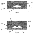
- Figs. 2a and 2b show, in accordance with yet another aspect of the invention, two successive stages of a shockwave interaction with a pocket of gas 22 attached to a surface 26 so as to cover and fill a V-shaped tapering depression 24.
- the tapering depression 24 is of a similar shape to that in Fig. 1 b , relative to the size of the tapering depression, the volume of gas in the pocket 22 is much greater than it is in Fig. 1 b.
- the width of the bubble could be of the order of 1 cm.
- Fig. 2a shows the shockwave 30 propagating through the medium 28 (which could be the same material as in previous embodiments or a different material could be used), in the direction of the arrow, towards the gas pocket 22.
- Fig. 2b shows a later stage in the interaction, after the shockwave 30 has struck the gas pocket 22.
- the portion 27 of the shockwave 30 that has struck the edge of the pocket of gas 22 is reflected as a result of the large change in density from the medium 28 to the gas 22.
- This reflected portion 27 forms a rarefaction fan which propagates away from the gas pocket 22 and therefore creates a low pressure region between the reflected portion 27 and the gas pocket 22.
- the medium 28 flows into this low pressure region as a jet 29 which then traverses the gas pocket 22, trapping a fraction of the gas therein between the tip of the jet 29 and the tapering depression 24 in the surface 26, thereby causing compression and heating of the gas in the manner previously described.
- Fig. 1 b shows a further configuration which is also suitable as an embodiment of this aspect of the invention.
- Fig. 3 shows a further embodiment of the previous aspect of the invention in which a pocket of gas 32 is attached to a target surface 36 in a tapering depression 34.
- This embodiment is different from those previously described in that the pocket of gas 32 is separated from the medium 38 by a prefabricated membrane 33.
- the prefabricated membrane 33 is frangible i.e. it is designed to break on the impact of the shockwave 40. Once the prefabricated membrane 33 has been broken by the impact of the shockwave 40, the shockwave 40 continues to propagate into the depression 34 compressing the pocket of gas 32 in the same manner as for the previous embodiments.
- Fig 4 is a variant of the embodiment shown in Fig. 2a .
- this embodiment there are multiple smaller depressions 42 at the bottom on a large depression 44.
- the pocket of gas 46 is partially received both by the large depression 44 and by the multiple smaller depressions 42.
- the jet formed when the shockwave (not shown) hits the pocket of gas 46 will highly compress multiple small volumes of the gas by trapping them in the small depressions 42, in a similar manner to that described above with reference to Figs. 2a and 2b .
- the diagrams shown are a vertical cross-section through a three-dimensional volume of gas and target surface and hence they depict embodiments that are rotationally symmetric.
- the surface could comprise discrete surface portions in the rotational direction either instead of, or as well as in the vertical cross-section shown.
- the target surface would be multifacetted. Each facet could give rise to separate but converging shockwaves.
- the apparatus can be used by creating a shockwave in the medium which is incident upon a volume of gas containing deuterated water vapour.
- the techniques described herein give rise to a peak pressure of -20 GPa which is sufficient to cause temperatures inside the collapsed volume of gas in excess of 1x10 6 Kelvin which can be sufficient for a nuclear fusion reaction of the deuterium atoms.
- the resulting neutrons could be used in other processes, or could be absorbed by a neutron absorber for conversion of the kinetic energy of the neutrons to thermal energy and thus conventional thermodynamic energy generation.
Landscapes
- Physics & Mathematics (AREA)
- Engineering & Computer Science (AREA)
- Plasma & Fusion (AREA)
- General Engineering & Computer Science (AREA)
- High Energy & Nuclear Physics (AREA)
- Chemical & Material Sciences (AREA)
- General Health & Medical Sciences (AREA)
- Toxicology (AREA)
- Health & Medical Sciences (AREA)
- Organic Chemistry (AREA)
- Chemical Kinetics & Catalysis (AREA)
- Physical Or Chemical Processes And Apparatus (AREA)
- Buffer Packaging (AREA)
- Air Bags (AREA)
- Chemical Vapour Deposition (AREA)
- Feeding, Discharge, Calcimining, Fusing, And Gas-Generation Devices (AREA)
- Surgical Instruments (AREA)
Priority Applications (2)
| Application Number | Priority Date | Filing Date | Title |
|---|---|---|---|
| EP16177349.4A EP3101655B1 (en) | 2010-05-07 | 2011-05-09 | Localised energy concentration method and device therefor |
| EP16177363.5A EP3101656B1 (en) | 2010-05-07 | 2011-05-09 | Localised energy concentration |
Applications Claiming Priority (2)
| Application Number | Priority Date | Filing Date | Title |
|---|---|---|---|
| GBGB1007655.2A GB201007655D0 (en) | 2010-05-07 | 2010-05-07 | Localised energy concentration |
| PCT/GB2011/050889 WO2011138622A1 (en) | 2010-05-07 | 2011-05-09 | Localised energy concentration |
Related Child Applications (4)
| Application Number | Title | Priority Date | Filing Date |
|---|---|---|---|
| EP16177363.5A Division EP3101656B1 (en) | 2010-05-07 | 2011-05-09 | Localised energy concentration |
| EP16177363.5A Division-Into EP3101656B1 (en) | 2010-05-07 | 2011-05-09 | Localised energy concentration |
| EP16177349.4A Division-Into EP3101655B1 (en) | 2010-05-07 | 2011-05-09 | Localised energy concentration method and device therefor |
| EP16177349.4A Division EP3101655B1 (en) | 2010-05-07 | 2011-05-09 | Localised energy concentration method and device therefor |
Publications (2)
| Publication Number | Publication Date |
|---|---|
| EP2567382A1 EP2567382A1 (en) | 2013-03-13 |
| EP2567382B1 true EP2567382B1 (en) | 2016-08-31 |
Family
ID=42314979
Family Applications (3)
| Application Number | Title | Priority Date | Filing Date |
|---|---|---|---|
| EP11721572.3A Active EP2567382B1 (en) | 2010-05-07 | 2011-05-09 | Localised energy concentration |
| EP16177349.4A Active EP3101655B1 (en) | 2010-05-07 | 2011-05-09 | Localised energy concentration method and device therefor |
| EP16177363.5A Active EP3101656B1 (en) | 2010-05-07 | 2011-05-09 | Localised energy concentration |
Family Applications After (2)
| Application Number | Title | Priority Date | Filing Date |
|---|---|---|---|
| EP16177349.4A Active EP3101655B1 (en) | 2010-05-07 | 2011-05-09 | Localised energy concentration method and device therefor |
| EP16177363.5A Active EP3101656B1 (en) | 2010-05-07 | 2011-05-09 | Localised energy concentration |
Country Status (15)
| Country | Link |
|---|---|
| US (3) | US9530524B2 (cg-RX-API-DMAC7.html) |
| EP (3) | EP2567382B1 (cg-RX-API-DMAC7.html) |
| JP (2) | JP5945533B2 (cg-RX-API-DMAC7.html) |
| KR (1) | KR101772525B1 (cg-RX-API-DMAC7.html) |
| CN (1) | CN102884586B (cg-RX-API-DMAC7.html) |
| AU (1) | AU2011249596B2 (cg-RX-API-DMAC7.html) |
| BR (1) | BR112012028461A2 (cg-RX-API-DMAC7.html) |
| CA (1) | CA2798586C (cg-RX-API-DMAC7.html) |
| ES (1) | ES2600679T3 (cg-RX-API-DMAC7.html) |
| GB (1) | GB201007655D0 (cg-RX-API-DMAC7.html) |
| MX (1) | MX2012012898A (cg-RX-API-DMAC7.html) |
| PL (1) | PL2567382T3 (cg-RX-API-DMAC7.html) |
| RU (1) | RU2547829C2 (cg-RX-API-DMAC7.html) |
| WO (1) | WO2011138622A1 (cg-RX-API-DMAC7.html) |
| ZA (1) | ZA201208197B (cg-RX-API-DMAC7.html) |
Families Citing this family (20)
| Publication number | Priority date | Publication date | Assignee | Title |
|---|---|---|---|---|
| GB0920816D0 (en) | 2009-11-27 | 2010-01-13 | Isis Innovation | Energy focussing |
| GB0920814D0 (en) | 2009-11-27 | 2010-01-13 | Isis Innovation | High velocity droplet impacts |
| GB201007655D0 (en) | 2010-05-07 | 2010-06-23 | Isis Innovation | Localised energy concentration |
| JP5901210B2 (ja) * | 2011-10-06 | 2016-04-06 | 浜松ホトニクス株式会社 | 放射線発生装置及び放射線発生方法 |
| GB201208939D0 (en) * | 2012-05-21 | 2012-07-04 | Isis Innovation | Localised energy concentration |
| GB201304047D0 (en) * | 2013-03-06 | 2013-04-17 | Isis Innovation | Localised Energy Concentration |
| GB201304046D0 (en) * | 2013-03-06 | 2013-04-17 | Isis Innovation | Localised energy concentration |
| CN104200849B (zh) * | 2014-08-22 | 2017-05-31 | 清华大学 | 利用空泡坍缩约束高温等离子体的方法 |
| CN110226072A (zh) * | 2016-05-03 | 2019-09-10 | 罗杰·S·斯丁汉姆 | 空化加热器 |
| IL271106B2 (en) * | 2019-12-02 | 2023-11-01 | Bar Zohar Dan | Device and method for nuclear fusion |
| CN114352277B (zh) * | 2022-01-18 | 2024-02-13 | 辽宁工程技术大学 | 一种基于可控冲击波的煤矿复合动力灾害防治方法 |
| GB2621189B (en) | 2022-08-05 | 2024-08-21 | First Light Fusion Ltd | Component for exposing fluid to an input shockwave |
| GB2621186A (en) * | 2022-08-05 | 2024-02-07 | First Light Fusion Ltd | Localised energy concentration |
| GB2621188B (en) | 2022-08-05 | 2025-02-12 | First Light Fusion Ltd | Method of manufacture of component for manipulating an input shockwave |
| GB2621187B (en) * | 2022-08-05 | 2024-12-11 | First Light Fusion Ltd | Component for manipulating an input shockwave |
| GB2630103A (en) | 2023-05-17 | 2024-11-20 | First Light Fusion Ltd | Component for Compressing Matter |
| GB2630107B (en) * | 2023-05-17 | 2025-09-24 | First Light Fusion Ltd | Component for Manipulating an Input Shockwave |
| GB2630109A (en) * | 2023-05-17 | 2024-11-20 | First Light Fusion Ltd | Component for Compressing Matter |
| GB2630106A (en) * | 2023-05-17 | 2024-11-20 | First Light Fusion Ltd | Component for Compressing Fuel |
| GB2638128A (en) * | 2024-01-31 | 2025-08-20 | First Light Fusion Ltd | Component for manipulating an input shockwave |
Family Cites Families (41)
| Publication number | Priority date | Publication date | Assignee | Title |
|---|---|---|---|---|
| US3481784A (en) * | 1966-06-15 | 1969-12-02 | John Karpovich | Method and apparatus for generating shock waves in a liquid |
| US3417829A (en) | 1966-09-16 | 1968-12-24 | Gulf Research Development Co | Conical jet bits |
| US3624239A (en) | 1970-02-11 | 1971-11-30 | Atomic Energy Commission | Pulsed laser-ignited thermonuclear reactor |
| US3858171A (en) * | 1972-10-12 | 1974-12-31 | J Pauletich | Electric sonic imploder |
| US3953617A (en) * | 1974-01-28 | 1976-04-27 | The United States Of America As Represented By The United States Energy Research & Development Administration | Method of producing encapsulated thermonuclear fuel particles |
| US4333796A (en) | 1978-05-19 | 1982-06-08 | Flynn Hugh G | Method of generating energy by acoustically induced cavitation fusion and reactor therefor |
| US4759894A (en) * | 1983-01-25 | 1988-07-26 | International Business Machines Corporation | Method and apparatus for producing an ultra-high controlled transient temperature with an electrical discharge |
| US4890603A (en) * | 1987-11-09 | 1990-01-02 | Filler William S | Extracorporeal shock wave lithotripsy employing non-focused, spherical-sector shock waves |
| JPH0812040B2 (ja) | 1990-10-23 | 1996-02-07 | 裕一 中村 | き裂制御爆破工法 |
| JP3220212B2 (ja) | 1992-03-18 | 2001-10-22 | 旭化成株式会社 | 水中衝撃波を利用した粉末の衝撃固化方法及び装置 |
| RU2056656C1 (ru) * | 1992-08-03 | 1996-03-20 | Виталий Алексеевич Киркинский | Способ получения свободных нейтронов |
| CN1112277A (zh) * | 1994-05-15 | 1995-11-22 | 林志强 | 聚变能置换器 |
| US7981368B2 (en) * | 1998-10-28 | 2011-07-19 | Covaris, Inc. | Method and apparatus for acoustically controlling liquid solutions in microfluidic devices |
| JP2001193381A (ja) | 2000-01-04 | 2001-07-17 | Sumitomo Electric Ind Ltd | プラズマ破壊装置およびこれを用いた破壊方法 |
| WO2002097823A1 (en) | 2001-05-25 | 2002-12-05 | Ut-Battelle, Llc | Methods and apparatus to induce d-d and d-t reactions |
| US6616338B2 (en) * | 2001-06-13 | 2003-09-09 | Emerson Power Transmission Manufacturing, L.P. | Extended load zone bearing |
| AUPR831501A0 (en) * | 2001-10-18 | 2001-11-08 | Symons, Ian Robert | Fusion reactor |
| US6916418B2 (en) | 2002-03-13 | 2005-07-12 | Harris Acoustic Products Corporation | Assembly and method for purifying water at a point of use and apparatus and method for testing same |
| US20030215046A1 (en) | 2002-05-16 | 2003-11-20 | Hornkohl Jason L. | Pressure generating structure |
| US8257282B2 (en) * | 2004-02-19 | 2012-09-04 | General Patent, Llc | Pressure pulse/shock wave apparatus for generating waves having plane, nearly plane, convergent off target or divergent characteristics |
| US6958569B1 (en) * | 2004-09-01 | 2005-10-25 | Impulse Devices, Inc. | Acoustic driver assembly for a spherical cavitation chamber |
| JP2006100382A (ja) * | 2004-09-28 | 2006-04-13 | Toshiba Corp | 半導体装置およびその製造方法 |
| CN100362330C (zh) | 2004-11-16 | 2008-01-16 | 中国科学院力学研究所 | 流体界面rt和rm不稳定性发生装置 |
| US8025371B1 (en) * | 2005-02-22 | 2011-09-27 | Synergy Innovations, Inc. | System and method for creating liquid droplet impact forced collapse of laser nanoparticle nucleated cavities |
| US7380918B2 (en) | 2005-02-22 | 2008-06-03 | Synergy Innovations, Inc. | Method and apparatus for forming high-speed liquid |
| US7445319B2 (en) | 2005-02-22 | 2008-11-04 | Synergy Innovations, Inc. | System and method for creating liquid droplet impact forced collapse of laser nanoparticle nucleated cavities for controlled nuclear reactions |
| EP1750018A3 (en) * | 2005-08-03 | 2011-12-14 | General Electric Company | Surfaces and articles resistant to impacting liquids |
| JP2007307682A (ja) * | 2006-05-22 | 2007-11-29 | Toshiba Plant Systems & Services Corp | 被改質材加工方法および被改質材加工装置 |
| US7887862B2 (en) | 2007-10-10 | 2011-02-15 | Industrias Centli S.A. De C.V. | Method and apparatus for separating, purifying, promoting interaction and improving combustion |
| US8945644B2 (en) | 2009-06-15 | 2015-02-03 | Cavitation Technologies, Inc. | Process to remove impurities from triacylglycerol oil |
| US9988651B2 (en) | 2009-06-15 | 2018-06-05 | Cavitation Technologies, Inc. | Processes for increasing bioalcohol yield from biomass |
| GB0920816D0 (en) | 2009-11-27 | 2010-01-13 | Isis Innovation | Energy focussing |
| GB0920814D0 (en) | 2009-11-27 | 2010-01-13 | Isis Innovation | High velocity droplet impacts |
| GB201007655D0 (en) | 2010-05-07 | 2010-06-23 | Isis Innovation | Localised energy concentration |
| US8440440B2 (en) | 2010-12-27 | 2013-05-14 | Intellicell Biosciences Inc. | Ultrasonic cavitation derived stromal or mesenchymal vascular extracts and cells derived therefrom obtained from adipose tissue and use thereof |
| US20140042088A1 (en) | 2011-01-20 | 2014-02-13 | Norifumi Yoshida | Bubble generating system and method for wastewater treatment |
| WO2012159033A1 (en) | 2011-05-19 | 2012-11-22 | Ecologix Cavitation Systems, Llc | Apparatus for heating fluids |
| GB201208939D0 (en) | 2012-05-21 | 2012-07-04 | Isis Innovation | Localised energy concentration |
| CN102759439B (zh) | 2012-06-26 | 2014-10-15 | 中国科学技术大学 | 一种用于激波管实验研究的界面生成装置 |
| GB201304046D0 (en) | 2013-03-06 | 2013-04-17 | Isis Innovation | Localised energy concentration |
| GB201304047D0 (en) | 2013-03-06 | 2013-04-17 | Isis Innovation | Localised Energy Concentration |
-
2010
- 2010-05-07 GB GBGB1007655.2A patent/GB201007655D0/en not_active Ceased
-
2011
- 2011-05-09 BR BR112012028461A patent/BR112012028461A2/pt not_active IP Right Cessation
- 2011-05-09 EP EP11721572.3A patent/EP2567382B1/en active Active
- 2011-05-09 CN CN201180023029.6A patent/CN102884586B/zh active Active
- 2011-05-09 CA CA2798586A patent/CA2798586C/en active Active
- 2011-05-09 PL PL11721572T patent/PL2567382T3/pl unknown
- 2011-05-09 RU RU2012149609/07A patent/RU2547829C2/ru not_active IP Right Cessation
- 2011-05-09 JP JP2013508557A patent/JP5945533B2/ja active Active
- 2011-05-09 ES ES11721572.3T patent/ES2600679T3/es active Active
- 2011-05-09 AU AU2011249596A patent/AU2011249596B2/en not_active Ceased
- 2011-05-09 WO PCT/GB2011/050889 patent/WO2011138622A1/en not_active Ceased
- 2011-05-09 KR KR1020127031561A patent/KR101772525B1/ko active Active
- 2011-05-09 MX MX2012012898A patent/MX2012012898A/es active IP Right Grant
- 2011-05-09 EP EP16177349.4A patent/EP3101655B1/en active Active
- 2011-05-09 US US13/696,690 patent/US9530524B2/en active Active
- 2011-05-09 EP EP16177363.5A patent/EP3101656B1/en active Active
-
2012
- 2012-10-31 ZA ZA2012/08197A patent/ZA201208197B/en unknown
-
2015
- 2015-06-09 JP JP2015116898A patent/JP6040287B2/ja active Active
-
2016
- 2016-07-01 US US15/200,382 patent/US10315180B2/en active Active
- 2016-07-07 US US15/203,854 patent/US10265674B2/en active Active
Non-Patent Citations (1)
| Title |
|---|
| None * |
Also Published As
| Publication number | Publication date |
|---|---|
| US10315180B2 (en) | 2019-06-11 |
| EP3101656A1 (en) | 2016-12-07 |
| CN102884586B (zh) | 2016-06-08 |
| ZA201208197B (en) | 2014-01-29 |
| JP6040287B2 (ja) | 2016-12-07 |
| GB201007655D0 (en) | 2010-06-23 |
| KR20130069657A (ko) | 2013-06-26 |
| US20130114774A1 (en) | 2013-05-09 |
| WO2011138622A1 (en) | 2011-11-10 |
| PL2567382T3 (pl) | 2017-01-31 |
| US20160343458A1 (en) | 2016-11-24 |
| CA2798586A1 (en) | 2011-11-10 |
| JP2013530388A (ja) | 2013-07-25 |
| ES2600679T3 (es) | 2017-02-10 |
| JP5945533B2 (ja) | 2016-07-05 |
| BR112012028461A2 (pt) | 2016-07-19 |
| US9530524B2 (en) | 2016-12-27 |
| EP3101655B1 (en) | 2018-08-22 |
| US20160314857A1 (en) | 2016-10-27 |
| RU2012149609A (ru) | 2014-06-20 |
| KR101772525B1 (ko) | 2017-08-29 |
| CA2798586C (en) | 2018-06-12 |
| JP2015222256A (ja) | 2015-12-10 |
| EP3101656B1 (en) | 2018-03-14 |
| MX2012012898A (es) | 2013-01-22 |
| CN102884586A (zh) | 2013-01-16 |
| RU2547829C2 (ru) | 2015-04-10 |
| EP3101655A1 (en) | 2016-12-07 |
| EP2567382A1 (en) | 2013-03-13 |
| AU2011249596A1 (en) | 2012-11-29 |
| AU2011249596B2 (en) | 2015-04-02 |
| US10265674B2 (en) | 2019-04-23 |
Similar Documents
| Publication | Publication Date | Title |
|---|---|---|
| EP2567382B1 (en) | Localised energy concentration | |
| EP2965321B1 (en) | Localised energy concentratoin | |
| EP2852953B1 (en) | Localised energy concentration | |
| US9984774B2 (en) | Localised energy concentration | |
| AU2014274540B2 (en) | Localised energy concentration |
Legal Events
| Date | Code | Title | Description |
|---|---|---|---|
| PUAI | Public reference made under article 153(3) epc to a published international application that has entered the european phase |
Free format text: ORIGINAL CODE: 0009012 |
|
| 17P | Request for examination filed |
Effective date: 20121206 |
|
| AK | Designated contracting states |
Kind code of ref document: A1 Designated state(s): AL AT BE BG CH CY CZ DE DK EE ES FI FR GB GR HR HU IE IS IT LI LT LU LV MC MK MT NL NO PL PT RO RS SE SI SK SM TR |
|
| DAX | Request for extension of the european patent (deleted) | ||
| GRAP | Despatch of communication of intention to grant a patent |
Free format text: ORIGINAL CODE: EPIDOSNIGR1 |
|
| INTG | Intention to grant announced |
Effective date: 20160225 |
|
| INTG | Intention to grant announced |
Effective date: 20160229 |
|
| GRAJ | Information related to disapproval of communication of intention to grant by the applicant or resumption of examination proceedings by the epo deleted |
Free format text: ORIGINAL CODE: EPIDOSDIGR1 |
|
| GRAJ | Information related to disapproval of communication of intention to grant by the applicant or resumption of examination proceedings by the epo deleted |
Free format text: ORIGINAL CODE: EPIDOSDIGR1 |
|
| GRAR | Information related to intention to grant a patent recorded |
Free format text: ORIGINAL CODE: EPIDOSNIGR71 |
|
| GRAS | Grant fee paid |
Free format text: ORIGINAL CODE: EPIDOSNIGR3 |
|
| GRAA | (expected) grant |
Free format text: ORIGINAL CODE: 0009210 |
|
| INTC | Intention to grant announced (deleted) | ||
| RAP1 | Party data changed (applicant data changed or rights of an application transferred) |
Owner name: OXFORD UNIVERSITY INNOVATION LIMITED |
|
| AK | Designated contracting states |
Kind code of ref document: B1 Designated state(s): AL AT BE BG CH CY CZ DE DK EE ES FI FR GB GR HR HU IE IS IT LI LT LU LV MC MK MT NL NO PL PT RO RS SE SI SK SM TR |
|
| INTG | Intention to grant announced |
Effective date: 20160726 |
|
| REG | Reference to a national code |
Ref country code: CH Ref legal event code: EP Ref country code: GB Ref legal event code: FG4D |
|
| REG | Reference to a national code |
Ref country code: IE Ref legal event code: FG4D |
|
| REG | Reference to a national code |
Ref country code: CH Ref legal event code: PK Free format text: BERICHTIGUNG INHABER |
|
| REG | Reference to a national code |
Ref country code: DE Ref legal event code: R096 Ref document number: 602011029815 Country of ref document: DE |
|
| REG | Reference to a national code |
Ref country code: AT Ref legal event code: REF Ref document number: 825602 Country of ref document: AT Kind code of ref document: T Effective date: 20161015 |
|
| REG | Reference to a national code |
Ref country code: SE Ref legal event code: TRGR |
|
| REG | Reference to a national code |
Ref country code: LT Ref legal event code: MG4D |
|
| RAP2 | Party data changed (patent owner data changed or rights of a patent transferred) |
Owner name: OXFORD UNIVERSITY INNOVATION LIMITED |
|
| REG | Reference to a national code |
Ref country code: NL Ref legal event code: MP Effective date: 20160831 |
|
| REG | Reference to a national code |
Ref country code: AT Ref legal event code: MK05 Ref document number: 825602 Country of ref document: AT Kind code of ref document: T Effective date: 20160831 |
|
| PG25 | Lapsed in a contracting state [announced via postgrant information from national office to epo] |
Ref country code: HR Free format text: LAPSE BECAUSE OF FAILURE TO SUBMIT A TRANSLATION OF THE DESCRIPTION OR TO PAY THE FEE WITHIN THE PRESCRIBED TIME-LIMIT Effective date: 20160831 Ref country code: LT Free format text: LAPSE BECAUSE OF FAILURE TO SUBMIT A TRANSLATION OF THE DESCRIPTION OR TO PAY THE FEE WITHIN THE PRESCRIBED TIME-LIMIT Effective date: 20160831 Ref country code: NO Free format text: LAPSE BECAUSE OF FAILURE TO SUBMIT A TRANSLATION OF THE DESCRIPTION OR TO PAY THE FEE WITHIN THE PRESCRIBED TIME-LIMIT Effective date: 20161130 Ref country code: FI Free format text: LAPSE BECAUSE OF FAILURE TO SUBMIT A TRANSLATION OF THE DESCRIPTION OR TO PAY THE FEE WITHIN THE PRESCRIBED TIME-LIMIT Effective date: 20160831 Ref country code: RS Free format text: LAPSE BECAUSE OF FAILURE TO SUBMIT A TRANSLATION OF THE DESCRIPTION OR TO PAY THE FEE WITHIN THE PRESCRIBED TIME-LIMIT Effective date: 20160831 |
|
| REG | Reference to a national code |
Ref country code: ES Ref legal event code: FG2A Ref document number: 2600679 Country of ref document: ES Kind code of ref document: T3 Effective date: 20170210 |
|
| PG25 | Lapsed in a contracting state [announced via postgrant information from national office to epo] |
Ref country code: NL Free format text: LAPSE BECAUSE OF FAILURE TO SUBMIT A TRANSLATION OF THE DESCRIPTION OR TO PAY THE FEE WITHIN THE PRESCRIBED TIME-LIMIT Effective date: 20160831 Ref country code: GR Free format text: LAPSE BECAUSE OF FAILURE TO SUBMIT A TRANSLATION OF THE DESCRIPTION OR TO PAY THE FEE WITHIN THE PRESCRIBED TIME-LIMIT Effective date: 20161201 Ref country code: LV Free format text: LAPSE BECAUSE OF FAILURE TO SUBMIT A TRANSLATION OF THE DESCRIPTION OR TO PAY THE FEE WITHIN THE PRESCRIBED TIME-LIMIT Effective date: 20160831 Ref country code: AT Free format text: LAPSE BECAUSE OF FAILURE TO SUBMIT A TRANSLATION OF THE DESCRIPTION OR TO PAY THE FEE WITHIN THE PRESCRIBED TIME-LIMIT Effective date: 20160831 |
|
| PG25 | Lapsed in a contracting state [announced via postgrant information from national office to epo] |
Ref country code: EE Free format text: LAPSE BECAUSE OF FAILURE TO SUBMIT A TRANSLATION OF THE DESCRIPTION OR TO PAY THE FEE WITHIN THE PRESCRIBED TIME-LIMIT Effective date: 20160831 Ref country code: RO Free format text: LAPSE BECAUSE OF FAILURE TO SUBMIT A TRANSLATION OF THE DESCRIPTION OR TO PAY THE FEE WITHIN THE PRESCRIBED TIME-LIMIT Effective date: 20160831 |
|
| REG | Reference to a national code |
Ref country code: FR Ref legal event code: PLFP Year of fee payment: 7 |
|
| PG25 | Lapsed in a contracting state [announced via postgrant information from national office to epo] |
Ref country code: BE Free format text: LAPSE BECAUSE OF FAILURE TO SUBMIT A TRANSLATION OF THE DESCRIPTION OR TO PAY THE FEE WITHIN THE PRESCRIBED TIME-LIMIT Effective date: 20160831 Ref country code: CZ Free format text: LAPSE BECAUSE OF FAILURE TO SUBMIT A TRANSLATION OF THE DESCRIPTION OR TO PAY THE FEE WITHIN THE PRESCRIBED TIME-LIMIT Effective date: 20160831 Ref country code: SM Free format text: LAPSE BECAUSE OF FAILURE TO SUBMIT A TRANSLATION OF THE DESCRIPTION OR TO PAY THE FEE WITHIN THE PRESCRIBED TIME-LIMIT Effective date: 20160831 Ref country code: SK Free format text: LAPSE BECAUSE OF FAILURE TO SUBMIT A TRANSLATION OF THE DESCRIPTION OR TO PAY THE FEE WITHIN THE PRESCRIBED TIME-LIMIT Effective date: 20160831 Ref country code: BG Free format text: LAPSE BECAUSE OF FAILURE TO SUBMIT A TRANSLATION OF THE DESCRIPTION OR TO PAY THE FEE WITHIN THE PRESCRIBED TIME-LIMIT Effective date: 20161130 Ref country code: PT Free format text: LAPSE BECAUSE OF FAILURE TO SUBMIT A TRANSLATION OF THE DESCRIPTION OR TO PAY THE FEE WITHIN THE PRESCRIBED TIME-LIMIT Effective date: 20170102 Ref country code: DK Free format text: LAPSE BECAUSE OF FAILURE TO SUBMIT A TRANSLATION OF THE DESCRIPTION OR TO PAY THE FEE WITHIN THE PRESCRIBED TIME-LIMIT Effective date: 20160831 |
|
| REG | Reference to a national code |
Ref country code: DE Ref legal event code: R097 Ref document number: 602011029815 Country of ref document: DE |
|
| PLBE | No opposition filed within time limit |
Free format text: ORIGINAL CODE: 0009261 |
|
| STAA | Information on the status of an ep patent application or granted ep patent |
Free format text: STATUS: NO OPPOSITION FILED WITHIN TIME LIMIT |
|
| 26N | No opposition filed |
Effective date: 20170601 |
|
| PG25 | Lapsed in a contracting state [announced via postgrant information from national office to epo] |
Ref country code: LU Free format text: LAPSE BECAUSE OF NON-PAYMENT OF DUE FEES Effective date: 20170531 Ref country code: SI Free format text: LAPSE BECAUSE OF FAILURE TO SUBMIT A TRANSLATION OF THE DESCRIPTION OR TO PAY THE FEE WITHIN THE PRESCRIBED TIME-LIMIT Effective date: 20160831 |
|
| PGFP | Annual fee paid to national office [announced via postgrant information from national office to epo] |
Ref country code: PL Payment date: 20170523 Year of fee payment: 7 Ref country code: SE Payment date: 20170530 Year of fee payment: 7 Ref country code: IT Payment date: 20170524 Year of fee payment: 7 Ref country code: ES Payment date: 20170601 Year of fee payment: 7 |
|
| REG | Reference to a national code |
Ref country code: CH Ref legal event code: PL |
|
| PG25 | Lapsed in a contracting state [announced via postgrant information from national office to epo] |
Ref country code: MC Free format text: LAPSE BECAUSE OF FAILURE TO SUBMIT A TRANSLATION OF THE DESCRIPTION OR TO PAY THE FEE WITHIN THE PRESCRIBED TIME-LIMIT Effective date: 20160831 |
|
| REG | Reference to a national code |
Ref country code: IE Ref legal event code: MM4A |
|
| PG25 | Lapsed in a contracting state [announced via postgrant information from national office to epo] |
Ref country code: CH Free format text: LAPSE BECAUSE OF NON-PAYMENT OF DUE FEES Effective date: 20170531 Ref country code: LI Free format text: LAPSE BECAUSE OF NON-PAYMENT OF DUE FEES Effective date: 20170531 |
|
| PG25 | Lapsed in a contracting state [announced via postgrant information from national office to epo] |
Ref country code: LU Free format text: LAPSE BECAUSE OF NON-PAYMENT OF DUE FEES Effective date: 20170509 |
|
| PG25 | Lapsed in a contracting state [announced via postgrant information from national office to epo] |
Ref country code: IE Free format text: LAPSE BECAUSE OF NON-PAYMENT OF DUE FEES Effective date: 20170509 |
|
| REG | Reference to a national code |
Ref country code: FR Ref legal event code: PLFP Year of fee payment: 8 |
|
| PG25 | Lapsed in a contracting state [announced via postgrant information from national office to epo] |
Ref country code: MT Free format text: LAPSE BECAUSE OF NON-PAYMENT OF DUE FEES Effective date: 20170509 |
|
| PG25 | Lapsed in a contracting state [announced via postgrant information from national office to epo] |
Ref country code: AL Free format text: LAPSE BECAUSE OF FAILURE TO SUBMIT A TRANSLATION OF THE DESCRIPTION OR TO PAY THE FEE WITHIN THE PRESCRIBED TIME-LIMIT Effective date: 20160831 |
|
| REG | Reference to a national code |
Ref country code: SE Ref legal event code: EUG |
|
| PG25 | Lapsed in a contracting state [announced via postgrant information from national office to epo] |
Ref country code: SE Free format text: LAPSE BECAUSE OF NON-PAYMENT OF DUE FEES Effective date: 20180510 |
|
| PG25 | Lapsed in a contracting state [announced via postgrant information from national office to epo] |
Ref country code: IT Free format text: LAPSE BECAUSE OF NON-PAYMENT OF DUE FEES Effective date: 20180509 |
|
| PG25 | Lapsed in a contracting state [announced via postgrant information from national office to epo] |
Ref country code: HU Free format text: LAPSE BECAUSE OF FAILURE TO SUBMIT A TRANSLATION OF THE DESCRIPTION OR TO PAY THE FEE WITHIN THE PRESCRIBED TIME-LIMIT; INVALID AB INITIO Effective date: 20110509 |
|
| REG | Reference to a national code |
Ref country code: ES Ref legal event code: FD2A Effective date: 20190913 |
|
| PG25 | Lapsed in a contracting state [announced via postgrant information from national office to epo] |
Ref country code: CY Free format text: LAPSE BECAUSE OF NON-PAYMENT OF DUE FEES Effective date: 20160831 Ref country code: ES Free format text: LAPSE BECAUSE OF NON-PAYMENT OF DUE FEES Effective date: 20180510 |
|
| PG25 | Lapsed in a contracting state [announced via postgrant information from national office to epo] |
Ref country code: MK Free format text: LAPSE BECAUSE OF FAILURE TO SUBMIT A TRANSLATION OF THE DESCRIPTION OR TO PAY THE FEE WITHIN THE PRESCRIBED TIME-LIMIT Effective date: 20160831 |
|
| PG25 | Lapsed in a contracting state [announced via postgrant information from national office to epo] |
Ref country code: PL Free format text: LAPSE BECAUSE OF NON-PAYMENT OF DUE FEES Effective date: 20180509 |
|
| PG25 | Lapsed in a contracting state [announced via postgrant information from national office to epo] |
Ref country code: TR Free format text: LAPSE BECAUSE OF FAILURE TO SUBMIT A TRANSLATION OF THE DESCRIPTION OR TO PAY THE FEE WITHIN THE PRESCRIBED TIME-LIMIT Effective date: 20160831 |
|
| PG25 | Lapsed in a contracting state [announced via postgrant information from national office to epo] |
Ref country code: IS Free format text: LAPSE BECAUSE OF FAILURE TO SUBMIT A TRANSLATION OF THE DESCRIPTION OR TO PAY THE FEE WITHIN THE PRESCRIBED TIME-LIMIT Effective date: 20161231 |
|
| REG | Reference to a national code |
Ref country code: DE Ref legal event code: R082 Ref document number: 602011029815 Country of ref document: DE |
|
| PGFP | Annual fee paid to national office [announced via postgrant information from national office to epo] |
Ref country code: GB Payment date: 20240514 Year of fee payment: 14 |
|
| PGFP | Annual fee paid to national office [announced via postgrant information from national office to epo] |
Ref country code: DE Payment date: 20240517 Year of fee payment: 14 |
|
| PGFP | Annual fee paid to national office [announced via postgrant information from national office to epo] |
Ref country code: FR Payment date: 20240523 Year of fee payment: 14 |