EP2567142B1 - Verfahren und system für kontinuierliches pumpen eines feststoffes - Google Patents
Verfahren und system für kontinuierliches pumpen eines feststoffes Download PDFInfo
- Publication number
- EP2567142B1 EP2567142B1 EP11721608.5A EP11721608A EP2567142B1 EP 2567142 B1 EP2567142 B1 EP 2567142B1 EP 11721608 A EP11721608 A EP 11721608A EP 2567142 B1 EP2567142 B1 EP 2567142B1
- Authority
- EP
- European Patent Office
- Prior art keywords
- carbon dioxide
- solid material
- solid
- stream
- pump
- Prior art date
- Legal status (The legal status is an assumption and is not a legal conclusion. Google has not performed a legal analysis and makes no representation as to the accuracy of the status listed.)
- Not-in-force
Links
- 239000011343 solid material Substances 0.000 title claims description 125
- 238000000034 method Methods 0.000 title claims description 39
- 238000005086 pumping Methods 0.000 title description 30
- CURLTUGMZLYLDI-UHFFFAOYSA-N Carbon dioxide Chemical compound O=C=O CURLTUGMZLYLDI-UHFFFAOYSA-N 0.000 claims description 358
- 239000001569 carbon dioxide Substances 0.000 claims description 176
- 229910002092 carbon dioxide Inorganic materials 0.000 claims description 176
- 239000007787 solid Substances 0.000 claims description 73
- 239000007788 liquid Substances 0.000 claims description 64
- 239000002002 slurry Substances 0.000 claims description 60
- 238000002156 mixing Methods 0.000 claims description 36
- 230000000750 progressive effect Effects 0.000 claims description 29
- 239000002245 particle Substances 0.000 claims description 28
- 239000003245 coal Substances 0.000 claims description 15
- 239000007789 gas Substances 0.000 claims description 11
- UFHFLCQGNIYNRP-UHFFFAOYSA-N Hydrogen Chemical compound [H][H] UFHFLCQGNIYNRP-UHFFFAOYSA-N 0.000 claims description 9
- 239000000203 mixture Substances 0.000 claims description 8
- 239000007921 spray Substances 0.000 claims description 8
- 229910052739 hydrogen Inorganic materials 0.000 claims description 7
- 239000001257 hydrogen Substances 0.000 claims description 7
- 239000003082 abrasive agent Substances 0.000 claims description 5
- 150000002431 hydrogen Chemical class 0.000 claims 2
- 238000007711 solidification Methods 0.000 claims 1
- 230000008023 solidification Effects 0.000 claims 1
- 239000000463 material Substances 0.000 description 29
- 230000008569 process Effects 0.000 description 9
- 235000011089 carbon dioxide Nutrition 0.000 description 8
- XLYOFNOQVPJJNP-UHFFFAOYSA-N water Substances O XLYOFNOQVPJJNP-UHFFFAOYSA-N 0.000 description 7
- 239000002817 coal dust Substances 0.000 description 4
- 238000002485 combustion reaction Methods 0.000 description 4
- 238000001816 cooling Methods 0.000 description 4
- 239000012530 fluid Substances 0.000 description 4
- 230000008901 benefit Effects 0.000 description 3
- 239000006227 byproduct Substances 0.000 description 3
- 238000000926 separation method Methods 0.000 description 3
- 239000000853 adhesive Substances 0.000 description 2
- 230000001070 adhesive effect Effects 0.000 description 2
- QVGXLLKOCUKJST-UHFFFAOYSA-N atomic oxygen Chemical compound [O] QVGXLLKOCUKJST-UHFFFAOYSA-N 0.000 description 2
- 230000008859 change Effects 0.000 description 2
- 238000006073 displacement reaction Methods 0.000 description 2
- 229910052760 oxygen Inorganic materials 0.000 description 2
- 239000001301 oxygen Substances 0.000 description 2
- 238000005057 refrigeration Methods 0.000 description 2
- 241000533950 Leucojum Species 0.000 description 1
- 235000019738 Limestone Nutrition 0.000 description 1
- NINIDFKCEFEMDL-UHFFFAOYSA-N Sulfur Chemical compound [S] NINIDFKCEFEMDL-UHFFFAOYSA-N 0.000 description 1
- 230000009471 action Effects 0.000 description 1
- 230000000712 assembly Effects 0.000 description 1
- 238000000429 assembly Methods 0.000 description 1
- 230000015572 biosynthetic process Effects 0.000 description 1
- 229910052799 carbon Inorganic materials 0.000 description 1
- 238000001311 chemical methods and process Methods 0.000 description 1
- 238000006243 chemical reaction Methods 0.000 description 1
- 230000006835 compression Effects 0.000 description 1
- 238000007906 compression Methods 0.000 description 1
- 238000010586 diagram Methods 0.000 description 1
- 239000006185 dispersion Substances 0.000 description 1
- 238000009826 distribution Methods 0.000 description 1
- 230000000694 effects Effects 0.000 description 1
- 238000005516 engineering process Methods 0.000 description 1
- 235000013305 food Nutrition 0.000 description 1
- 239000002778 food additive Substances 0.000 description 1
- 235000013373 food additive Nutrition 0.000 description 1
- 238000002309 gasification Methods 0.000 description 1
- 238000000227 grinding Methods 0.000 description 1
- 238000010438 heat treatment Methods 0.000 description 1
- 239000008240 homogeneous mixture Substances 0.000 description 1
- 229910052500 inorganic mineral Inorganic materials 0.000 description 1
- 239000006028 limestone Substances 0.000 description 1
- 230000014759 maintenance of location Effects 0.000 description 1
- 238000004519 manufacturing process Methods 0.000 description 1
- 239000011707 mineral Substances 0.000 description 1
- 239000003595 mist Substances 0.000 description 1
- 238000012986 modification Methods 0.000 description 1
- 230000004048 modification Effects 0.000 description 1
- 239000002006 petroleum coke Substances 0.000 description 1
- 238000010248 power generation Methods 0.000 description 1
- 230000002250 progressing effect Effects 0.000 description 1
- 238000010926 purge Methods 0.000 description 1
- 238000000859 sublimation Methods 0.000 description 1
- 230000008022 sublimation Effects 0.000 description 1
- 229910052717 sulfur Inorganic materials 0.000 description 1
- 239000011593 sulfur Substances 0.000 description 1
Images


Classifications
-
- F—MECHANICAL ENGINEERING; LIGHTING; HEATING; WEAPONS; BLASTING
- F04—POSITIVE - DISPLACEMENT MACHINES FOR LIQUIDS; PUMPS FOR LIQUIDS OR ELASTIC FLUIDS
- F04C—ROTARY-PISTON, OR OSCILLATING-PISTON, POSITIVE-DISPLACEMENT MACHINES FOR LIQUIDS; ROTARY-PISTON, OR OSCILLATING-PISTON, POSITIVE-DISPLACEMENT PUMPS
- F04C2/00—Rotary-piston machines or pumps
- F04C2/08—Rotary-piston machines or pumps of intermeshing-engagement type, i.e. with engagement of co-operating members similar to that of toothed gearing
- F04C2/10—Rotary-piston machines or pumps of intermeshing-engagement type, i.e. with engagement of co-operating members similar to that of toothed gearing of internal-axis type with the outer member having more teeth or tooth-equivalents, e.g. rollers, than the inner member
- F04C2/107—Rotary-piston machines or pumps of intermeshing-engagement type, i.e. with engagement of co-operating members similar to that of toothed gearing of internal-axis type with the outer member having more teeth or tooth-equivalents, e.g. rollers, than the inner member with helical teeth
- F04C2/1071—Rotary-piston machines or pumps of intermeshing-engagement type, i.e. with engagement of co-operating members similar to that of toothed gearing of internal-axis type with the outer member having more teeth or tooth-equivalents, e.g. rollers, than the inner member with helical teeth the inner and outer member having a different number of threads and one of the two being made of elastic materials, e.g. Moineau type
-
- B—PERFORMING OPERATIONS; TRANSPORTING
- B65—CONVEYING; PACKING; STORING; HANDLING THIN OR FILAMENTARY MATERIAL
- B65G—TRANSPORT OR STORAGE DEVICES, e.g. CONVEYORS FOR LOADING OR TIPPING, SHOP CONVEYOR SYSTEMS OR PNEUMATIC TUBE CONVEYORS
- B65G53/00—Conveying materials in bulk through troughs, pipes or tubes by floating the materials or by flow of gas, liquid or foam
- B65G53/30—Conveying materials in bulk through pipes or tubes by liquid pressure
-
- F—MECHANICAL ENGINEERING; LIGHTING; HEATING; WEAPONS; BLASTING
- F04—POSITIVE - DISPLACEMENT MACHINES FOR LIQUIDS; PUMPS FOR LIQUIDS OR ELASTIC FLUIDS
- F04C—ROTARY-PISTON, OR OSCILLATING-PISTON, POSITIVE-DISPLACEMENT MACHINES FOR LIQUIDS; ROTARY-PISTON, OR OSCILLATING-PISTON, POSITIVE-DISPLACEMENT PUMPS
- F04C13/00—Adaptations of machines or pumps for special use, e.g. for extremely high pressures
- F04C13/001—Pumps for particular liquids
- F04C13/002—Pumps for particular liquids for homogeneous viscous liquids
- F04C13/004—Pumps for particular liquids for homogeneous viscous liquids with means for fluidising or diluting the material being pumped
-
- F—MECHANICAL ENGINEERING; LIGHTING; HEATING; WEAPONS; BLASTING
- F17—STORING OR DISTRIBUTING GASES OR LIQUIDS
- F17D—PIPE-LINE SYSTEMS; PIPE-LINES
- F17D1/00—Pipe-line systems
- F17D1/08—Pipe-line systems for liquids or viscous products
- F17D1/088—Pipe-line systems for liquids or viscous products for solids or suspensions of solids in liquids, e.g. slurries
-
- F—MECHANICAL ENGINEERING; LIGHTING; HEATING; WEAPONS; BLASTING
- F23—COMBUSTION APPARATUS; COMBUSTION PROCESSES
- F23K—FEEDING FUEL TO COMBUSTION APPARATUS
- F23K1/00—Preparation of lump or pulverulent fuel in readiness for delivery to combustion apparatus
- F23K1/02—Mixing solid fuel with a liquid, e.g. preparing slurries
-
- F—MECHANICAL ENGINEERING; LIGHTING; HEATING; WEAPONS; BLASTING
- F04—POSITIVE - DISPLACEMENT MACHINES FOR LIQUIDS; PUMPS FOR LIQUIDS OR ELASTIC FLUIDS
- F04C—ROTARY-PISTON, OR OSCILLATING-PISTON, POSITIVE-DISPLACEMENT MACHINES FOR LIQUIDS; ROTARY-PISTON, OR OSCILLATING-PISTON, POSITIVE-DISPLACEMENT PUMPS
- F04C11/00—Combinations of two or more machines or pumps, each being of rotary-piston or oscillating-piston type; Pumping installations
- F04C11/001—Combinations of two or more machines or pumps, each being of rotary-piston or oscillating-piston type; Pumping installations of similar working principle
- F04C11/003—Combinations of two or more machines or pumps, each being of rotary-piston or oscillating-piston type; Pumping installations of similar working principle having complementary function
-
- Y—GENERAL TAGGING OF NEW TECHNOLOGICAL DEVELOPMENTS; GENERAL TAGGING OF CROSS-SECTIONAL TECHNOLOGIES SPANNING OVER SEVERAL SECTIONS OF THE IPC; TECHNICAL SUBJECTS COVERED BY FORMER USPC CROSS-REFERENCE ART COLLECTIONS [XRACs] AND DIGESTS
- Y02—TECHNOLOGIES OR APPLICATIONS FOR MITIGATION OR ADAPTATION AGAINST CLIMATE CHANGE
- Y02P—CLIMATE CHANGE MITIGATION TECHNOLOGIES IN THE PRODUCTION OR PROCESSING OF GOODS
- Y02P30/00—Technologies relating to oil refining and petrochemical industry
Definitions
- the present invention relates to methods and a system of continuously pumping a solid material by mixing the solid material with carbon dioxide to form a slurry within a pump.
- the solid material may be mixed with a carrier fluid, such as water, to form a slurry.
- the slurry includes particles of the solid material suspended in the carrier fluid. The slurry can then be pumped and pressurized to a required high pressure.
- Coal and water are one type of common pressurized slurry.
- the pressurized slurries of coal and water are typically highly viscous, thus increasing the pressurization and transport of such slurries.
- water as the carrier fluid of the slurry, there may be energy penalties (i.e., losses of energy due to the heating of the water) in processes that require thermally processing the slurry.
- hoppers containing the solid are first pressurized and then emptied into a pressurized system. After a first hopper is emptied, the system is closed and then a second hopper is pressurized and then emptied into the pressurized system. Because each hopper must be pressurized before being introduced into the pressurized system, this system provides only a substantially discontinuous feed of the pressurized solid.
- U.S. Patent No. 4,488,838 to Herud discloses methods and apparatus for feeding a dry supply material (e.g., crushed or pulverized coal) from a supply source into a reactor through use of a liquefied gas (e.g., liquefied carbon dioxide).
- a liquefied gas e.g., liquefied carbon dioxide
- the liquefied gas is slurried into the dry supply material during its progress through a conveyor toward the higher pressure zone of the conveyor output.
- a fraction of the liquefied gas input backtracks through the supply material toward the lower pressured conveyor inlet, and by expansion and cooling progressively solidifies into solid particles which intermingle with and substantially fill the interstices between the supply material particles as they progress through the conveyor.
- the resulting slurry exits the conveyer and is heated in heat exchangers to convert the liquefied gas into a superheated gas, which is then partially separated from the dry supply material in a cyclone separator. Remaining superheated gas and dry supply material are directed to a high pressure process, such as to a coal gasifier reactor.
- U.S. Patent No. 4,166,731 to Staege discloses a process for the continuous introduction of fine-grained and dust-like solids into a pressurized reaction space.
- the process includes simultaneously passing separate streams of coal dust and gaseous carbon dioxide (CO 2 ) through a cooler to form separate dry ice and low temperature coal dust streams, which are then combined in a mixing screw.
- the mixture of dry ice and coal dust is concentrated in a pressure device, and the condensed mixture is directed through a heat exchanger and a preheater to completely sublime the dry ice.
- the gaseous CO 2 and coal dust are separated in a cyclone, and the gaseous CO 2 is recycled to repeat the process.
- U.S. Patent No. 8,182,252 to Amburgey et al. discloses a pump system including a feeder assembly that advances materials, such as foods, food additives, and other materials for human or animal consumption, to a progressing cavity pump.
- the feeder assembly includes an elongated hopper which is open at its top and bottom ends.
- An auger housing including a pair of augers receives materials from the open bottom end of the elongated hopper.
- the present invention relates to a methods of continuously producing a pressurized slurry of a solid material and liquid carbon dioxide according to claims 1 and 15.
- the solid material comprises at least one of coal and particles of an abrasive material.
- the mixture of the solid material and solid carbon dioxide may be fed to the first cavity of the progressive cavity pump at an ambient pressure.
- the pressurized slurry formed in the third cavity of the progressive cavity pump may have a pressure of at least about 830 psi (5723 kPa).
- the present invention generally relates to a system and methods of continuously producing a pressurized slurry of a solid material and liquid carbon dioxide.
- a continuous feed of particles of the solid material and a continuous feed of solid carbon dioxide, or dry ice, particles are combined in a mixing container.
- the combined solid material and solid carbon dioxide are then fed to a pump where the solid carbon dioxide sublimates into a gas that is subsequently liquidized forming the pressurized slurry of the solid material and liquid carbon dioxide.
- the pressurized slurry of the solid material and liquid carbon dioxide may be fed directly to a high-pressure process.
- the system and methods of continuously producing the pressurized slurry of solid material and liquid carbon dioxide of the present invention may be used to form a pressurized slurry of any solid material in which a continuous high-pressure feed of the solid material is desirable.
- the solid material stream may comprise coal.
- the solid material may comprise particles of an abrasive material such as an abrasive grit material. Such particles of abrasive materials may be sprayed onto an adhesive sheet.
- the particles of abrasive material adhere to the adhesive sheet while the liquid carbon dioxide sublimates, forming a sandpaper-type material.
- the solid material may be a mineral of value such as, for example, sulfur, petroleum coke, and limestone.
- the pressurized slurry of solid material and liquid carbon dioxide formed using the system and method of the present invention may be fed to a slurry pipeline for transportation to a desired location.
- the continuous solid material pumping system 100 includes a mixing container 106 for receiving a solid material stream 102 and a solid carbon dioxide material stream 104.
- the solid material stream 102 and the solid carbon dioxide material stream 104 are mixed in the mixing container 106, forming a mixed solid material and solid carbon dioxide stream 108.
- the mixed solid material and solid carbon dioxide stream 108 is fed to a progressive cavity pump 112. Within the progressive cavity pump 112, at least a portion of the solid carbon dioxide sublimates to form a gaseous carbon dioxide.
- the combined pressure increase from the gaseous carbon dioxide and compression provided by the progressive cavity pump 112 causes the gaseous carbon dioxide to liquefy forming a liquid carbon dioxide.
- the liquid carbon dioxide mixes with the solid material, forming a pressurized slurry of the solid material and the liquid carbon dioxide exits the progressive cavity pump 112 as a pressurized slurry stream 110.
- the solid material stream 102 may be formed of very fine particulates to provide for efficient delivery of the solid material stream 102 to the mixing container 106 and to facilitate a roughly equal dispersion of the solid material stream 102 and the solid carbon dioxide material stream 104 in the mixing container 106.
- the solid material stream 102 may include particles having a particle size distribution so that about 70% to about 90% of the solid material stream 102 passes through an ASTM No. 200 U.S.A. standard testing sieve as defined in ASTM Specification E11-04, which is entitled Standard Specification for Wire Cloth and Sieves for Testing Purposes.
- the solid carbon dioxide material stream 104 may also be formed of very fine particulates.
- the solid carbon dioxide material stream 104 may be formed of small snow-flake like particles having a diameter less than about 20 mm.
- the solid carbon dioxide material stream 104 may be formed of particles having a diameter from about 1 mm to about 10 mm.
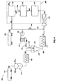
- FIG. 2 illustrates a more detailed schematic of one embodiment of the continuous solid material pumping system 100 of FIG. 1 .
- the solid material stream 102 may be fed from a bulk solid material delivery source 114 to a sealed hopper 116.
- the solid material stream 102 may be transported from the bulk solid material delivery source 114 to the sealed hopper 116 via a vibration unit (not shown) or other transportation means as known in the art.
- the solid material stream 102 may be provided from the bulk solid material delivery source 114 as fine particulates, or, alternatively, a combination of crushing and grinding equipment (not shown) may be used to pulverize the solid material of the stream 102 before the solid material stream 102 enters the sealed hopper 116.
- a gaseous carbon dioxide stream 118 may be fed to the sealed hopper 116 to purge atmospheric air trapped in interstitial spaces between particles of the solid material.
- the atmospheric air exits the sealed hopper 116 as an atmospheric air and gaseous carbon dioxide stream 120.
- the sealed hopper 116 may be maintained at about ambient pressure, 14.6 psi (101.3 kPa), by controlling the flow rates of the gaseous carbon dioxide stream 118 and the atmospheric air and gaseous carbon dioxide stream 120.
- the sealed hopper 116 may include a shaker or agitator (not shown) or other material conveyance apparatus to transport the solid material through the sealed hopper 116 to the mixing container 106.
- a solid material conveyor 122 such as a screw auger may be used to continuously transport the solid material stream 102 to the mixing container 106.
- a liquid carbon dioxide stream 124 may be supplied from a bulk carbon dioxide delivery source 126.
- Carbon dioxide is a byproduct of many chemical processes including power production.
- the bulk carbon dioxide delivery source 126 may, therefore, be supplied with carbon dioxide from a carbon dioxide source that may otherwise have required sequestering of the carbon dioxide byproduct.
- the liquid carbon dioxide stream 124 may be thermally manipulated to form particles of solid carbon dioxide.
- the liquid carbon dioxide stream 124 is supplied from the bulk carbon dioxide delivery source 126 at a pressure ranging from about 145 psi (1013 kPa) to about 294 psi (2026 kPa) and a temperature of about -30°C to about -15°C.
- the liquid carbon dioxide stream 124 is transported to a refrigeration unit 130 via a pump 128.
- the temperature of the liquid carbon dioxide stream 124 is cooled in the refrigeration unit 130, forming a cooled liquid carbon dioxide stream 124'.
- the cooled liquid carbon dioxide stream 124' may be at or below about the triple point temperature of carbon dioxide, about -56°C.
- the triple point temperature is the temperature at which the carbon dioxide may be present in more than one phase, for example, the carbon dioxide may be present as a gas, a solid, and a liquid simultaneously.
- the cooled liquid carbon dioxide stream 124' is then directed through a spray nozzle 132 into the mixing container 106.
- the spray nozzle 132 may be configured to produce a fine mist of the cooled liquid carbon dioxide stream 124' so that the solid carbon dioxide material stream 104 is formed as a stream of fine snowflake-like material.
- a control valve 134 maybe used to control the flow rate of the cooled liquid carbon dioxide stream 124' to the spray nozzle 132.
- a commercially available dry ice maker or dry ice blaster may be used to form the solid carbon dioxide material stream 104. Such dry ice makers and dry ice blasters are commercially available from numerous sources including, but not limited to, Cold Jet, LLC (Loveland, OH) and IceTech America, Inc. (West Chester, OH).
- the particles of solid material stream 102 and of the solid carbon dioxide material 104 are mixed in the mixing container 106 to form the mixed solid material and solid carbon dioxide stream 108.
- the mixed solid material and solid carbon dioxide stream 108 may comprise an at least substantially homogenous mixture formed of the solid material stream 102 and the solid carbon dioxide material stream 104.
- the mixed solid material and solid carbon dioxide stream 108 may be formed of about 60 wt% to about 80 wt% solid material and about 40 wt% to about 20 wt% solid carbon dioxide.
- the temperature and the pressure of the mixing container 106 may be controlled to maintain the solid carbon dioxide material stream 104 in a solid state within the mixing container 106.
- the adiabatic expansion of the cooled liquid carbon dioxide stream 124' provides enough cooling capacity to maintain the solid carbon dioxide material stream 104 in the solid state within the mixing container 106.
- the mixed solid material and solid carbon dioxide stream 108 from the mixing container 106 is fed to the progressive cavity pump 112.
- the progressive cavity pump 112 may be a suitable positive displacement pump known in the art including, for example, a Moineau-type pump or an auger pump. Such positive displacement pumps are commercially available from numerous sources including, but not limited to, Moyno, Inc. (Springfield, OH) and Seepex GmbH (Battrop, Germany).
- FIG. 3 illustrates an enlarged partial internal view of one embodiment of the progressive cavity pump 112. As shown in FIG. 3 , the progressive cavity pump 112 includes a first cavity 206, a second cavity 208, and a third cavity 210. However, in some embodiments, the progressive cavity pump 112 may include more than three cavities, such as, for example, four to fifteen cavities. The number of cavities of the progressive cavity pump 112 will vary based on the desired pressure and phase characteristics of the pressurized slurry 110.
- the progressive cavity pump 112 includes an inlet 212 for receiving the mixed solid material and solid carbon dioxide stream 108 and an outlet 214 for removing the pressurized slurry 110.
- the progressive cavity pump 112 also includes a rotor 202 that is driven by a motor 207.
- the progressive cavity pump 112 may include a feed auger portion 205 and a pumping portion 209.
- the feed auger portion 205 may include, for example, blades 211 attached to the rotor 202 which mechanically force the mixed solid material and solid carbon dioxide stream 108 to the pumping portion 209.
- the rotor 202 forms a tight, substantially continuous seal with the inner surface of an elastomeric stator 204 forming the cavities 206, 208, and 210 between the rotor 202 and the elastomeric stator 204.
- the cavities 206, 208, and 210 move longitudinally (i.e., the first cavity 206 becomes the second cavity 208 and the second cavity 208 becomes the third cavity 210) through the pumping portion 209 of progressive cavity pump 112 as the rotor 202 is rotated in cooperation with the engaged inner surface of the elastomeric stator 204, but the shapes and volumes of the cavities 206, 208, and 210 remain constant.
- the mixed solid material and solid carbon dioxide stream 108 is introduced into progressive cavity pump 112 through the inlet 212 and progresses through the steer auger portion 205 to the first cavity 206 of the pumping portion 209.
- the temperature of the solid carbon dioxide increases, causing the solid carbon dioxide to sublimate forming a gaseous carbon dioxide.
- the gaseous carbon dioxide exhibits a pressure up to 800 times that of the solid carbon dioxide.
- heat is transferred from the solid material to the solid carbon dioxide causing the increase in temperature and subsequent sublimation of the solid carbon dioxide.
- the solid material stream 102 in the mixed solid material and solid carbon dioxide stream 108 may be at about 20°C and the solid carbon dioxide material stream 104 in the mixed solid carbon dioxide stream 108 may be at about -78°C.
- the heat transferred from solid material to the solid carbon dioxide may increase the temperature of the solid carbon dioxide to about -40°C, at which point the solid carbon dioxide sublimates.
- the pressure in the first cavity 206 may increase up to about 2758 kPa (400 psi).
- the pressure increase from the gaseous carbon dioxide combined with the compressive force of the pumping action from the pumping portion 209 of the progressive cavity pump 112 causes the gaseous carbon dioxide to liquefy within the second cavity 208, forming a liquid carbon dioxide.
- the pressure in the second cavity 208 may increase up to about 6205 kPa (900 psi).
- the temperature of the carbon dioxide and the solid material may both be about -40°C in the second cavity 208.
- the liquid carbon dioxide mixes with the solid material in the third cavity 210 producing the pressurized slurry.
- the pressurized slurry exits the progressive cavity pump 112 through the outlet 214.
- the pressure in the third cavity 210 may be up to about 6895 kPa (1000 psi).
- the temperature of the carbon dioxide and the solid material may remain at about -40°C in the third cavity.
- phase change characteristics of the carbon dioxide are described with respect to specific cavities 206, 208, 210, it is understood that the sequence of phase changes of the carbon dioxide may take place anywhere throughout the progressive cavity pump 112.
- additional liquid carbon dioxide from the liquid carbon dioxide stream 124 may be fed to the pressurized slurry as desired via a control valve 134.
- a backpressure regulator 136 may be placed after the progressive cavity pump 112 to maintain the pressurized slurry 110 above the liquefaction pressure of the liquid carbon dioxide.
- the backpressure regulator 136 may be set to maintain the pressurized slurry 110 at a pressure of about 840 psi (5723 kPa) to about 1000 psi (6895 kPa) at about 20°C to about 30°C.
- the pressurized slurry 110 may then be processed as desired or, in some embodiments, the pressurized slurry 110 may be fed to a pipeline 111 to transport the pressurized slurry to a desired location, such as, a factory.
- the continuous solid material pumping system 100 of the present invention may offer at least one of several advantages over other solid material pumping systems known in the art.
- conventional solid material pumping system technologies combine a liquid carbon dioxide with the solid material to form a slurry.
- the continuous solid material pumping system 100 utilizes the phase change properties of the carbon dioxide to increase the pressure of the pressurized slurry 110.
- the continuous solid material pumping system 100 of the present invention utilizes fewer pumps and pressurizing apparatuses than a conventional solid material pumping system.
- conventional solid material pumping systems such as a lock hopper system, require pressurization of the solid material before mixing the solid material and the liquid carbon dioxide in order to prevent a large pressure drop and gasification of the liquid carbon dioxide.
- Such pressurization of the solid material is performed in batch operations via lock hopper assemblies, thus preventing a continuous feed of the solid material.
- the solid material pumping system 100 of the present invention does not require pre-pressurization of the solid material stream 102 and, thus, the continuous solid material pumping system 100 of the present invention may be used to provide a continuous feed of the solid material stream 102.
- the carbon dioxide used to form the pressurized slurry 110 may be a recycled byproduct from other processes, eliminating the need to sequester the carbon dioxide.
- FIG. 4 is a schematic drawing of one embodiment of the continuous solid material pumping system 100 of FIG. 2 further comprising a combustion and separation system 300.
- the solid material stream 102 comprises a combustible solid material, low-rank-coal being one example.
- the pressurized slurry 110 produced by the continuous solid material pumping system 100 is fed to a high-pressure reactor 140, such as a slurry-fed gasifier.
- the pressurized slurry 110 may be fed to the high-pressure reactor 140 through a spray nozzle (not shown).
- Feeding the pressurized slurry 110 through the spray nozzle may help improve the rate of combustion of the solid material within the pressurized slurry 110 rather than feeding the pressurized slurry 110 as a bulk fluid.
- the solid material is combusted in the high-pressure reactor 140, producing a syngas 142.
- the syngas 142 comprises a mixture of hydrogen gas and gaseous carbon dioxide. In one embodiment, the syngas 142 maybe about 66% hydrogen gas and about 33% gaseous carbon dioxide by volume.
- the syngas 142 may then cooled via a heat exchanger 144 and the components thereof separated via a separator 148.
- the heat exchanger 144 may be used to cool the syngas 142 to about 20°C and a pump 146 may be used to pressurize the cooled syngas 142 above the liquefaction pressure of the gaseous carbon dioxide, about 830 psi (5723 kPa) to form a two-phase syngas 142'. Heat absorbed by the heat exchanger 144 during cooling of the syngas may be recycled and used to promote other processes of the continuous solid material pumping system 100. The cooling and pressurizing of the syngas 142 forms a two-phase syngas 142' wherein the carbon dioxide is present as a liquid and the hydrogen is a gas.
- the two-phase syngas 142' may then be sent to the separator 148 to separate the liquid carbon dioxide and the hydrogen gas, forming a recycled liquid carbon dioxide stream 150 and a hydrogen gas stream 152. At least a portion of the recycled liquid carbon dioxide stream 150 may be combined with the liquid carbon dioxide stream 124 and fed to the continuous solid material pumping system 100.
- the combustion and separation system 300 of FIG. 4 maybe as much as 4% more efficient at converting coal to hydrogen then a conventional coal and water slurry pumping system.
- Conventional coal and water slurry pumping systems consume significantly larger quantities of oxygen than a coal and liquid carbon dioxide slurry.
- the continuous solid material pumping system 100 provides a continuous feed of the pressurized slurry 110 to the high-pressure reactor 140, no heat or oxygen is lost caused by a break in the feed to the reactor.
Landscapes
- Engineering & Computer Science (AREA)
- Mechanical Engineering (AREA)
- General Engineering & Computer Science (AREA)
- Chemical & Material Sciences (AREA)
- Combustion & Propulsion (AREA)
- Health & Medical Sciences (AREA)
- Public Health (AREA)
- Water Supply & Treatment (AREA)
- Carbon And Carbon Compounds (AREA)
Claims (25)
- Verfahren umfassend:Leiten eines gekühlten flüssigen Kohlendioxidstroms (124') durch eine Sprühdüse (132) in einen Mischcontainer (106), um Tröpfchen von flüssigem Kohledioxid zu bilden;adiabatische Ausdehnung der Tröpfchen von flüssigem Kohlendioxid in dem Mischcontainer (106), um einen festen Kohlendioxidstrom (104) zu bilden, der Partikel von festem Kohlendioxid umfasst;Mischen des festen Kohlendioxidstroms (104) mit einem Feststoffstrom (102),der Partikel von Feststoff in einem Mischcontainer (106) umfasst, um einen Mischstrom (108) des Feststoffs und des festen Kohlendioxids zu bilden; undZuführen des Mischstroms (108) des Feststoffs und des festen Kohlendioxids durch eine Pumpe (112), um eine Suspension (110) aus dem Feststoff und einem flüssigen Kohlendioxid zu bilden.
- Verfahren nach Anspruch 1, wobei das Zuführen des Mischstroms (108) des Feststoffs und des festen Kohlendioxids durch eine Pumpe (112), um eine Suspension (110) aus dem Feststoff und einem flüssigen Kohlendioxid zu bilden, innerhalb der Pumpe (112) umfasst:Sublimieren des festen Kohlendioxids, um gasförmiges Kohlendioxid zu bilden;Erhöhen des Druckes, um das gasförmige Kohlendioxid zu verflüssigen, um ein flüssiges Kohlendioxid zu bilden; undMischen des flüssigen Kohlendioxids und des Feststoffs, um die Suspension aus dem Feststoff und dem flüssigen Kohlendioxid zu bilden.
- Verfahren nach Anspruch 2, wobei das Sublimieren des festen Kohlendioxids, um ein gasförmiges Kohlendioxid zu bilden, den Druck in der Pumpe (112) auf einen Verflüssigungsdruck des gasförmigen Kohlendioxids erhöht.
- Verfahren nach Anspruch 1, wobei das Mischen des festen Kohlendioxidstroms (104) mit einem Feststoffstrom (102) das Mischen von ungefähr 60 Gew.-% Feststoff und ungefähr 40 Gew.-% festem Kohlendioxid umfasst.
- Verfahren nach Anspruch 1, wobei das Mischen des festen Kohlendioxidstroms (104) mit einem Feststoffstrom (102) das Zuführen einer kontinuierlichen Zufuhr von Partikeln des Feststoffs zu dem Mischcontainer (106) umfasst.
- Verfahren nach Anspruch 5, ferner umfassend das Ersetzen von atmosphärischer Luft aus interstitiellen Bereichen in der kontinuierlichen Zufuhr von Partikeln des Feststoffs mit einem gasförmigen Kohlendioxid.
- Verfahren nach Anspruch 5, wobei das Zuführen einer kontinuierlichen Zufuhr der Partikel des Feststoffs zu dem Mischcontainer (106) das Zuführen einer kontinuierlichen Zufuhr von Kohle oder Partikeln eines abrasiven Stoffs zu dem Mischcontainer (106) umfasst.
- Verfahren nach Anspruch 1, wobei das Mischen des festen Kohlendioxidstroms (104) mit einem Feststoffstrom (102) das Mischen des Feststoffstroms (102) und des festen Kohlendioxidstroms (104) in dem Mischcontainer (106) bei einem Umgebungsdruck umfasst.
- Verfahren nach Anspruch 1, wobei das Mischen des festen Kohlendioxidstroms (104) mit einem Feststoffstrom (102) Bereitstellen einer kontinuierlichen Zufuhr von den Partikeln des festen Kohlendioxids zu dem Mischcontainer (106) umfasst.
- Verfahren nach Anspruch 1, ferner umfassend Zuführen der Suspension (110) des Feststoffs und des flüssigen Kohlendioxids zu einem Reaktor (140).
- Verfahren nach Anspruch 10, ferner umfassend Verbrennen der Suspension (110) des Feststoffs und des flüssigen Kohlendioxids, um ein Synthesegas (142) zu produzieren, das Wasserstoff und Kohlendioxid umfasst.
- Verfahren nach Anspruch 11, ferner umfassend Trennen des Wasserstoffs (152) in einem Gaszustand von dem Kohlendioxid (150) in einem flüssigen Zustand.
- Verfahren nach Anspruch 12, ferner umfassend Verfestigen des getrennten flüssigen Kohlendioxids (150), um Partikel von festem Kohlendioxid zu bilden und Zuführen der Partikel des festen Kohlendioxids zu dem Mischcontainer (106).
- Verfahren nach Anspruch 1, ferner umfassend Transportieren der Suspension (110) des Feststoffs und des flüssigen Kohlendioxids durch eine Leitung (111).
- Verfahren zum kontinuierlichen Produzieren einer unter Druck stehenden Suspension (110), umfassend:Zuführen einer Mischung (108) von einem Feststoff und einem festen Kohlendioxid in einen ersten Hohlraum (205) einer Exzenterschneckenpumpe (112);Sublimieren zumindest eines Teils des festen Kohlendioxids innerhalb des ersten Hohlraums (205), um ein gasförmiges Kohlendioxid zu bilden;Erhöhen des Drucks in einem zweiten Hohlraum (208) der Exzenterschneckenpumpe (112);Verflüssigen von zumindest einem Teil des gasförmigen Kohlendioxids innerhalb des zweiten Hohlraums (208), um ein flüssiges Kohlendioxid zu bilden;undMischen des flüssigem Kohlendioxids und des Feststoffs in einem dritten Hohlraum (210) der Exzenterschneckenpumpe (112), um eine unter Druck stehende Suspension (110) zu bilden.
- Verfahren nach Anspruch 15, wobei das Zuführen einer Mischung eines Feststoffs und eines festen Kohlendioxids in einen ersten Hohlraum (205) der Exzenterschneckenpumpe (112) Zuführen einer Mischung (108) des Feststoffs und des festen Kohlendioxids bei Umgebungsdruck in den ersten Hohlraum (205) der Exzenterschneckenpumpe (112) umfasst.
- Verfahren nach Anspruch 15, wobei das Mischen des flüssigen Kohlendioxids und des Feststoffs in einem dritten Hohlraum (210) der Exzenterschneckenpumpe (112), um eine unter Druck stehende Suspension (110) zu bilden, Bilden der unter Drucks stehenden Suspension (110) umfasst, die einen Druck von zumindest ungefähr 5723 kPa (830 psi) aufweist.
- Verfahren nach Anspruch 15, ferner umfassend das Hinzufügen von zusätzlichem flüssigem Kohlendioxid (124) zu der unter Druck stehenden Suspension (110).
- System (100) umfassend:einen Vorrat (126) von unter Druck stehendem flüssigem Kohlendioxid;eine Sprühdüse (132), die konfiguriert ist zum Zerstreuen von Partikeln des unter Druck stehenden flüssigen Kohlendioxids in den Mischer (106);einen Mischer (106), der konfiguriert ist zum Mischen von Partikeln eines Feststoffs und festem Kohlendioxid; undeine Pumpe (112), die an den Mischer (106) gekoppelt ist, wobei die Pumpe (112) konfiguriert ist zum Sublimieren des festen Kohlendioxids, um ein gasförmiges Kohlendioxid zu bilden, zum Verflüssigen des gasförmigen Kohlendioxids, um ein flüssiges Kohlendioxid zu bilden und zum Mischen des flüssigen Kohlendioxids und des Feststoffs, um eine unter Druck stehende Suspension (110) zu bilden.
- System nach Anspruch 19, wobei die Pumpe (112) eine Exzenterschneckenpumpe umfasst, die zumindest drei Hohlräume (205, 208, 210) umfasst.
- System nach Anspruch 19, ferner umfassend einen Gegendruckregulator (136), der an einen Auslass (214) der Pumpe (112) gekoppelt ist.
- System nach Anspruch 19, ferner umfassend eine Quelle (114) von Feststoff, die pulverisierte Kohle umfasst.
- System nach Anspruch 19, ferner umfassend zumindest einen Reaktor (140), der konfiguriert ist zum Verbrennen der unter Druck stehenden Suspension (110), um ein Synthesegas (142) zu produzieren, das Wasserstoff und Kohlendioxid umfasst.
- System nach Anspruch 23, ferner umfassend einen Trenner (148), der konfiguriert ist zum Trennen des Wasserstoffs (152) in einem Gaszustand von dem Kohlendioxid (150) in einem flüssigen Zustand.
- System nach Anspruch 24, ferner umfassend zumindest eine Leitung, die konfiguriert ist zum Empfangen des flüssigen Kohlendioxids (150) von dem Trenner (148) und Zurückführen des flüssigen Kohlendioxids (150) zu dem Mischer (106) für eine Verfestigung.
Applications Claiming Priority (2)
| Application Number | Priority Date | Filing Date | Title |
|---|---|---|---|
| US12/775,290 US8597386B2 (en) | 2010-05-06 | 2010-05-06 | Method and system for continuously pumping a solid material and method and system for hydrogen formation |
| PCT/US2011/035579 WO2011140479A1 (en) | 2010-05-06 | 2011-05-06 | Method and system for continuously pumping a solid material and method and system for hydrogen formation |
Publications (2)
| Publication Number | Publication Date |
|---|---|
| EP2567142A1 EP2567142A1 (de) | 2013-03-13 |
| EP2567142B1 true EP2567142B1 (de) | 2015-07-08 |
Family
ID=44242497
Family Applications (1)
| Application Number | Title | Priority Date | Filing Date |
|---|---|---|---|
| EP11721608.5A Not-in-force EP2567142B1 (de) | 2010-05-06 | 2011-05-06 | Verfahren und system für kontinuierliches pumpen eines feststoffes |
Country Status (3)
| Country | Link |
|---|---|
| US (1) | US8597386B2 (de) |
| EP (1) | EP2567142B1 (de) |
| WO (1) | WO2011140479A1 (de) |
Families Citing this family (6)
| Publication number | Priority date | Publication date | Assignee | Title |
|---|---|---|---|---|
| US9086164B2 (en) | 2012-06-29 | 2015-07-21 | General Electric Company | Apparatus and method of delivering a fluid using a non-mechanical eductor pump and lock hopper |
| KR101412015B1 (ko) * | 2012-10-29 | 2014-07-01 | 한국과학기술연구원 | 고체산을 이용한 합성가스 제조 방법 |
| DE202014010877U1 (de) * | 2014-02-24 | 2017-01-02 | Jung & Co. Gerätebau GmbH | Zweispindelige Schraubenspindelpumpe in einflutiger Bauweise |
| IN2015MU00086A (de) * | 2015-01-09 | 2015-04-10 | Deven Supercriticals Pvt Ltd | |
| CN107101431B (zh) * | 2017-05-19 | 2022-07-05 | 中山市雪冷宫冷冻科技有限公司 | 一种干冰冷冻处理输送线 |
| CN116510598A (zh) * | 2023-05-04 | 2023-08-01 | 索通齐力炭材料有限公司 | 预焙阳极在线炭碗自动填充供料装备及方法 |
Family Cites Families (20)
| Publication number | Priority date | Publication date | Assignee | Title |
|---|---|---|---|---|
| US3933001A (en) * | 1974-04-23 | 1976-01-20 | Airco, Inc. | Distributing a carbon dioxide slurry |
| US3976443A (en) | 1974-12-18 | 1976-08-24 | Texaco Inc. | Synthesis gas from solid carbonaceous fuel |
| DE2648048C2 (de) | 1976-10-23 | 1983-12-22 | Krupp-Koppers Gmbh, 4300 Essen | Verfahren zum kontinuierlichen Einschleusen von feinkörnigen bis staubförmigen Feststoffen in einen unter erhöhtem Druck stehenden Reaktionsraum |
| US4127008A (en) * | 1976-11-01 | 1978-11-28 | Lewis Tyree Jr | Method and apparatus for cooling material using liquid CO2 |
| US4206610A (en) | 1978-04-14 | 1980-06-10 | Arthur D. Little, Inc. | Method and apparatus for transporting coal as a coal/liquid carbon dioxide slurry |
| US4191028A (en) * | 1978-06-22 | 1980-03-04 | United States Of America As Represented By The Secretary Of The Navy | Dry ice, liquid pulse pump cooling system |
| US4488838A (en) | 1982-05-24 | 1984-12-18 | Textron Inc. | Process and apparatus for feeding particulate material into a pressure vessel |
| US4613429A (en) * | 1984-07-05 | 1986-09-23 | University Of Pittsburgh | Process for removing mineral matter from coal |
| US4765781A (en) * | 1985-03-08 | 1988-08-23 | Southwestern Public Service Company | Coal slurry system |
| US4721420A (en) | 1985-09-03 | 1988-01-26 | Arthur D. Little, Inc. | Pipeline transportation of coarse coal-liquid carbon dioxide slurry |
| US4995234A (en) * | 1989-10-02 | 1991-02-26 | Chicago Bridge & Iron Technical Services Company | Power generation from LNG |
| US5715702A (en) * | 1996-11-15 | 1998-02-10 | Frigoscandia Equipment Ab | Refrigeration system |
| US5902359A (en) * | 1997-04-15 | 1999-05-11 | Empresa Colombiana de Petroleos--Ecopetrol | On-line and/or batch process for production of fuel mixtures consisting of coal/asphaltenes, fuel oil/heavy crude oil, surfactant and water (CCTA), and the obtained products |
| US20070107465A1 (en) * | 2001-05-04 | 2007-05-17 | Battelle Energy Alliance, Llc | Apparatus for the liquefaction of gas and methods relating to same |
| US7303597B2 (en) | 2002-10-15 | 2007-12-04 | Pratt & Whitney Rocketdyne, Inc. | Method and apparatus for continuously feeding and pressurizing a solid material into a high pressure system |
| US6688115B1 (en) * | 2003-01-28 | 2004-02-10 | Air Products And Chemicals, Inc. | High-pressure delivery system for ultra high purity liquid carbon dioxide |
| US9050117B2 (en) * | 2006-08-28 | 2015-06-09 | The Regents Of The University Of California | Dynamic cooling of human skin using a nontoxic cryogen with no ozone depletion and minimal global warming potential |
| US7794215B2 (en) * | 2007-02-12 | 2010-09-14 | Regency Technologies Llc | High pressure slurry plunger pump with clean fluid valve arrangement |
| US8182252B2 (en) | 2007-10-30 | 2012-05-22 | Moyno, Inc. | Progressing cavity pump with split stator |
| US20100050687A1 (en) * | 2008-09-04 | 2010-03-04 | Alstom Technology Ltd | Liquefaction of gaseous carbon-dioxide remainders during anti-sublimation process |
-
2010
- 2010-05-06 US US12/775,290 patent/US8597386B2/en not_active Expired - Fee Related
-
2011
- 2011-05-06 EP EP11721608.5A patent/EP2567142B1/de not_active Not-in-force
- 2011-05-06 WO PCT/US2011/035579 patent/WO2011140479A1/en not_active Ceased
Also Published As
| Publication number | Publication date |
|---|---|
| US8597386B2 (en) | 2013-12-03 |
| EP2567142A1 (de) | 2013-03-13 |
| WO2011140479A1 (en) | 2011-11-10 |
| US20110272636A1 (en) | 2011-11-10 |
Similar Documents
| Publication | Publication Date | Title |
|---|---|---|
| EP2567142B1 (de) | Verfahren und system für kontinuierliches pumpen eines feststoffes | |
| US7615198B2 (en) | Apparatus for continuously feeding and pressurizing a solid material into a high pressure system | |
| CN1293341C (zh) | 天然气液化装置及其相关方法 | |
| US4765781A (en) | Coal slurry system | |
| US4206610A (en) | Method and apparatus for transporting coal as a coal/liquid carbon dioxide slurry | |
| AU2009286701B2 (en) | Process and apparatus for removing gaseous contaminants from gas stream comprising gaseous contaminants | |
| CN107850264B (zh) | 处理lng导入终端处的液化天然气流的方法和系统 | |
| US4488838A (en) | Process and apparatus for feeding particulate material into a pressure vessel | |
| US8900334B2 (en) | Method for supplying an entrained-flow gasification reactor with fuel from a storage container | |
| CN108291769B (zh) | 从受污染的烃物料流去除co2的方法 | |
| JP2013540706A (ja) | 天然ガスハイドレート製造装置及び天然ガスハイドレート製造方法 | |
| WO2008122556A3 (en) | Method and apparatus for separating one or more c2+ hydrocarbons from a mixed phase hydrocarbon stream | |
| FI87545C (fi) | Kontinuerlig metod foer krossning av mineraler | |
| KR101766402B1 (ko) | 가스 하이드레이트 펠릿 재기화 장치 | |
| JP2003252804A (ja) | ハイドレート製造方法及び装置 | |
| CN101522381B (zh) | 冷却的新鲜混凝土的生产方法和装置 | |
| KR101692260B1 (ko) | 가스 하이드레이트 펠릿 성형장치 | |
| JP2003055675A (ja) | ガスハイドレートの生成方法および生成装置、ならびにガスハイドレートの生成システム | |
| CN119546555A (zh) | 用于生产气体水合物的系统和方法 | |
| CN210048683U (zh) | 一种从混合气中回收乙烷的系统 | |
| EP3242741B1 (de) | System und verfahren zur kontinuierlichen zuführung und abführung von feststoffmaterial zu und von einem unter hohen druck betriebenen extraktionsbehälter | |
| CN111747816A (zh) | 一种从混合气中回收乙烷的系统及工艺 | |
| JP2010235718A (ja) | ガスハイドレート製造装置及びその制御方法 | |
| CN112871270A (zh) | 一种气体水合物半连续分解装置 | |
| JP2003275965A (ja) | 粒状ドライアイスの供給方法および供給装置 |
Legal Events
| Date | Code | Title | Description |
|---|---|---|---|
| PUAI | Public reference made under article 153(3) epc to a published international application that has entered the european phase |
Free format text: ORIGINAL CODE: 0009012 |
|
| 17P | Request for examination filed |
Effective date: 20121121 |
|
| AK | Designated contracting states |
Kind code of ref document: A1 Designated state(s): AL AT BE BG CH CY CZ DE DK EE ES FI FR GB GR HR HU IE IS IT LI LT LU LV MC MK MT NL NO PL PT RO RS SE SI SK SM TR |
|
| DAX | Request for extension of the european patent (deleted) | ||
| 17Q | First examination report despatched |
Effective date: 20130829 |
|
| RIC1 | Information provided on ipc code assigned before grant |
Ipc: F17D 1/08 20060101AFI20140902BHEP Ipc: F04C 11/00 20060101ALI20140902BHEP Ipc: F04C 13/00 20060101ALI20140902BHEP Ipc: B65G 53/30 20060101ALI20140902BHEP Ipc: F23K 1/02 20060101ALI20140902BHEP Ipc: F04C 2/107 20060101ALI20140902BHEP |
|
| GRAP | Despatch of communication of intention to grant a patent |
Free format text: ORIGINAL CODE: EPIDOSNIGR1 |
|
| INTG | Intention to grant announced |
Effective date: 20141110 |
|
| GRAS | Grant fee paid |
Free format text: ORIGINAL CODE: EPIDOSNIGR3 |
|
| GRAP | Despatch of communication of intention to grant a patent |
Free format text: ORIGINAL CODE: EPIDOSNIGR1 |
|
| INTG | Intention to grant announced |
Effective date: 20150410 |
|
| GRAA | (expected) grant |
Free format text: ORIGINAL CODE: 0009210 |
|
| AK | Designated contracting states |
Kind code of ref document: B1 Designated state(s): AL AT BE BG CH CY CZ DE DK EE ES FI FR GB GR HR HU IE IS IT LI LT LU LV MC MK MT NL NO PL PT RO RS SE SI SK SM TR |
|
| REG | Reference to a national code |
Ref country code: GB Ref legal event code: FG4D |
|
| REG | Reference to a national code |
Ref country code: AT Ref legal event code: REF Ref document number: 735688 Country of ref document: AT Kind code of ref document: T Effective date: 20150715 Ref country code: CH Ref legal event code: EP |
|
| REG | Reference to a national code |
Ref country code: IE Ref legal event code: FG4D |
|
| REG | Reference to a national code |
Ref country code: DE Ref legal event code: R096 Ref document number: 602011017681 Country of ref document: DE |
|
| RAP2 | Party data changed (patent owner data changed or rights of a patent transferred) |
Owner name: ORBITAL ATK, INC. |
|
| REG | Reference to a national code |
Ref country code: SE Ref legal event code: TRGR Ref country code: DE Ref legal event code: R081 Ref document number: 602011017681 Country of ref document: DE Owner name: ORBITAL ATK, INC. (N.D.GES.D.STAATES DELAWARE), US Free format text: FORMER OWNER: ALLIANT TECHSYSTEMS INC., MINNEAPOLIS, MINN., US |
|
| REG | Reference to a national code |
Ref country code: AT Ref legal event code: MK05 Ref document number: 735688 Country of ref document: AT Kind code of ref document: T Effective date: 20150708 |
|
| REG | Reference to a national code |
Ref country code: NL Ref legal event code: MP Effective date: 20150708 |
|
| REG | Reference to a national code |
Ref country code: LT Ref legal event code: MG4D |
|
| PG25 | Lapsed in a contracting state [announced via postgrant information from national office to epo] |
Ref country code: FI Free format text: LAPSE BECAUSE OF FAILURE TO SUBMIT A TRANSLATION OF THE DESCRIPTION OR TO PAY THE FEE WITHIN THE PRESCRIBED TIME-LIMIT Effective date: 20150708 Ref country code: LV Free format text: LAPSE BECAUSE OF FAILURE TO SUBMIT A TRANSLATION OF THE DESCRIPTION OR TO PAY THE FEE WITHIN THE PRESCRIBED TIME-LIMIT Effective date: 20150708 Ref country code: LT Free format text: LAPSE BECAUSE OF FAILURE TO SUBMIT A TRANSLATION OF THE DESCRIPTION OR TO PAY THE FEE WITHIN THE PRESCRIBED TIME-LIMIT Effective date: 20150708 Ref country code: NO Free format text: LAPSE BECAUSE OF FAILURE TO SUBMIT A TRANSLATION OF THE DESCRIPTION OR TO PAY THE FEE WITHIN THE PRESCRIBED TIME-LIMIT Effective date: 20151008 Ref country code: GR Free format text: LAPSE BECAUSE OF FAILURE TO SUBMIT A TRANSLATION OF THE DESCRIPTION OR TO PAY THE FEE WITHIN THE PRESCRIBED TIME-LIMIT Effective date: 20151009 |
|
| PG25 | Lapsed in a contracting state [announced via postgrant information from national office to epo] |
Ref country code: ES Free format text: LAPSE BECAUSE OF FAILURE TO SUBMIT A TRANSLATION OF THE DESCRIPTION OR TO PAY THE FEE WITHIN THE PRESCRIBED TIME-LIMIT Effective date: 20150708 Ref country code: AT Free format text: LAPSE BECAUSE OF FAILURE TO SUBMIT A TRANSLATION OF THE DESCRIPTION OR TO PAY THE FEE WITHIN THE PRESCRIBED TIME-LIMIT Effective date: 20150708 Ref country code: IS Free format text: LAPSE BECAUSE OF FAILURE TO SUBMIT A TRANSLATION OF THE DESCRIPTION OR TO PAY THE FEE WITHIN THE PRESCRIBED TIME-LIMIT Effective date: 20151108 Ref country code: PL Free format text: LAPSE BECAUSE OF FAILURE TO SUBMIT A TRANSLATION OF THE DESCRIPTION OR TO PAY THE FEE WITHIN THE PRESCRIBED TIME-LIMIT Effective date: 20150708 Ref country code: HR Free format text: LAPSE BECAUSE OF FAILURE TO SUBMIT A TRANSLATION OF THE DESCRIPTION OR TO PAY THE FEE WITHIN THE PRESCRIBED TIME-LIMIT Effective date: 20150708 Ref country code: PT Free format text: LAPSE BECAUSE OF FAILURE TO SUBMIT A TRANSLATION OF THE DESCRIPTION OR TO PAY THE FEE WITHIN THE PRESCRIBED TIME-LIMIT Effective date: 20151109 Ref country code: RS Free format text: LAPSE BECAUSE OF FAILURE TO SUBMIT A TRANSLATION OF THE DESCRIPTION OR TO PAY THE FEE WITHIN THE PRESCRIBED TIME-LIMIT Effective date: 20150708 |
|
| REG | Reference to a national code |
Ref country code: DE Ref legal event code: R097 Ref document number: 602011017681 Country of ref document: DE |
|
| PG25 | Lapsed in a contracting state [announced via postgrant information from national office to epo] |
Ref country code: DK Free format text: LAPSE BECAUSE OF FAILURE TO SUBMIT A TRANSLATION OF THE DESCRIPTION OR TO PAY THE FEE WITHIN THE PRESCRIBED TIME-LIMIT Effective date: 20150708 Ref country code: EE Free format text: LAPSE BECAUSE OF FAILURE TO SUBMIT A TRANSLATION OF THE DESCRIPTION OR TO PAY THE FEE WITHIN THE PRESCRIBED TIME-LIMIT Effective date: 20150708 Ref country code: SK Free format text: LAPSE BECAUSE OF FAILURE TO SUBMIT A TRANSLATION OF THE DESCRIPTION OR TO PAY THE FEE WITHIN THE PRESCRIBED TIME-LIMIT Effective date: 20150708 Ref country code: CZ Free format text: LAPSE BECAUSE OF FAILURE TO SUBMIT A TRANSLATION OF THE DESCRIPTION OR TO PAY THE FEE WITHIN THE PRESCRIBED TIME-LIMIT Effective date: 20150708 |
|
| PLBE | No opposition filed within time limit |
Free format text: ORIGINAL CODE: 0009261 |
|
| STAA | Information on the status of an ep patent application or granted ep patent |
Free format text: STATUS: NO OPPOSITION FILED WITHIN TIME LIMIT |
|
| REG | Reference to a national code |
Ref country code: FR Ref legal event code: PLFP Year of fee payment: 6 |
|
| PG25 | Lapsed in a contracting state [announced via postgrant information from national office to epo] |
Ref country code: RO Free format text: LAPSE BECAUSE OF FAILURE TO SUBMIT A TRANSLATION OF THE DESCRIPTION OR TO PAY THE FEE WITHIN THE PRESCRIBED TIME-LIMIT Effective date: 20150708 |
|
| 26N | No opposition filed |
Effective date: 20160411 |
|
| PG25 | Lapsed in a contracting state [announced via postgrant information from national office to epo] |
Ref country code: SI Free format text: LAPSE BECAUSE OF FAILURE TO SUBMIT A TRANSLATION OF THE DESCRIPTION OR TO PAY THE FEE WITHIN THE PRESCRIBED TIME-LIMIT Effective date: 20150708 Ref country code: BE Free format text: LAPSE BECAUSE OF NON-PAYMENT OF DUE FEES Effective date: 20160531 |
|
| PG25 | Lapsed in a contracting state [announced via postgrant information from national office to epo] |
Ref country code: LU Free format text: LAPSE BECAUSE OF FAILURE TO SUBMIT A TRANSLATION OF THE DESCRIPTION OR TO PAY THE FEE WITHIN THE PRESCRIBED TIME-LIMIT Effective date: 20160506 Ref country code: BE Free format text: LAPSE BECAUSE OF FAILURE TO SUBMIT A TRANSLATION OF THE DESCRIPTION OR TO PAY THE FEE WITHIN THE PRESCRIBED TIME-LIMIT Effective date: 20150708 |
|
| REG | Reference to a national code |
Ref country code: CH Ref legal event code: PL |
|
| PG25 | Lapsed in a contracting state [announced via postgrant information from national office to epo] |
Ref country code: CH Free format text: LAPSE BECAUSE OF NON-PAYMENT OF DUE FEES Effective date: 20160531 Ref country code: LI Free format text: LAPSE BECAUSE OF NON-PAYMENT OF DUE FEES Effective date: 20160531 |
|
| REG | Reference to a national code |
Ref country code: IE Ref legal event code: MM4A |
|
| REG | Reference to a national code |
Ref country code: FR Ref legal event code: PLFP Year of fee payment: 7 |
|
| PG25 | Lapsed in a contracting state [announced via postgrant information from national office to epo] |
Ref country code: IE Free format text: LAPSE BECAUSE OF NON-PAYMENT OF DUE FEES Effective date: 20160506 |
|
| PG25 | Lapsed in a contracting state [announced via postgrant information from national office to epo] |
Ref country code: NL Free format text: LAPSE BECAUSE OF FAILURE TO SUBMIT A TRANSLATION OF THE DESCRIPTION OR TO PAY THE FEE WITHIN THE PRESCRIBED TIME-LIMIT Effective date: 20150708 |
|
| PGFP | Annual fee paid to national office [announced via postgrant information from national office to epo] |
Ref country code: FR Payment date: 20170525 Year of fee payment: 7 Ref country code: GB Payment date: 20170530 Year of fee payment: 7 Ref country code: DE Payment date: 20170530 Year of fee payment: 7 |
|
| PGFP | Annual fee paid to national office [announced via postgrant information from national office to epo] |
Ref country code: IT Payment date: 20170524 Year of fee payment: 7 Ref country code: SE Payment date: 20170530 Year of fee payment: 7 |
|
| PG25 | Lapsed in a contracting state [announced via postgrant information from national office to epo] |
Ref country code: SM Free format text: LAPSE BECAUSE OF FAILURE TO SUBMIT A TRANSLATION OF THE DESCRIPTION OR TO PAY THE FEE WITHIN THE PRESCRIBED TIME-LIMIT Effective date: 20150708 Ref country code: CY Free format text: LAPSE BECAUSE OF FAILURE TO SUBMIT A TRANSLATION OF THE DESCRIPTION OR TO PAY THE FEE WITHIN THE PRESCRIBED TIME-LIMIT Effective date: 20150708 Ref country code: HU Free format text: LAPSE BECAUSE OF FAILURE TO SUBMIT A TRANSLATION OF THE DESCRIPTION OR TO PAY THE FEE WITHIN THE PRESCRIBED TIME-LIMIT; INVALID AB INITIO Effective date: 20110506 |
|
| PG25 | Lapsed in a contracting state [announced via postgrant information from national office to epo] |
Ref country code: MC Free format text: LAPSE BECAUSE OF FAILURE TO SUBMIT A TRANSLATION OF THE DESCRIPTION OR TO PAY THE FEE WITHIN THE PRESCRIBED TIME-LIMIT Effective date: 20150708 Ref country code: TR Free format text: LAPSE BECAUSE OF FAILURE TO SUBMIT A TRANSLATION OF THE DESCRIPTION OR TO PAY THE FEE WITHIN THE PRESCRIBED TIME-LIMIT Effective date: 20150708 Ref country code: MT Free format text: LAPSE BECAUSE OF NON-PAYMENT OF DUE FEES Effective date: 20160531 Ref country code: MK Free format text: LAPSE BECAUSE OF FAILURE TO SUBMIT A TRANSLATION OF THE DESCRIPTION OR TO PAY THE FEE WITHIN THE PRESCRIBED TIME-LIMIT Effective date: 20150708 |
|
| PG25 | Lapsed in a contracting state [announced via postgrant information from national office to epo] |
Ref country code: BG Free format text: LAPSE BECAUSE OF FAILURE TO SUBMIT A TRANSLATION OF THE DESCRIPTION OR TO PAY THE FEE WITHIN THE PRESCRIBED TIME-LIMIT Effective date: 20150708 |
|
| PG25 | Lapsed in a contracting state [announced via postgrant information from national office to epo] |
Ref country code: AL Free format text: LAPSE BECAUSE OF FAILURE TO SUBMIT A TRANSLATION OF THE DESCRIPTION OR TO PAY THE FEE WITHIN THE PRESCRIBED TIME-LIMIT Effective date: 20150708 |
|
| REG | Reference to a national code |
Ref country code: DE Ref legal event code: R119 Ref document number: 602011017681 Country of ref document: DE |
|
| REG | Reference to a national code |
Ref country code: SE Ref legal event code: EUG |
|
| GBPC | Gb: european patent ceased through non-payment of renewal fee |
Effective date: 20180506 |
|
| PG25 | Lapsed in a contracting state [announced via postgrant information from national office to epo] |
Ref country code: SE Free format text: LAPSE BECAUSE OF NON-PAYMENT OF DUE FEES Effective date: 20180507 |
|
| PG25 | Lapsed in a contracting state [announced via postgrant information from national office to epo] |
Ref country code: GB Free format text: LAPSE BECAUSE OF NON-PAYMENT OF DUE FEES Effective date: 20180506 Ref country code: IT Free format text: LAPSE BECAUSE OF NON-PAYMENT OF DUE FEES Effective date: 20180506 Ref country code: FR Free format text: LAPSE BECAUSE OF NON-PAYMENT OF DUE FEES Effective date: 20180531 Ref country code: DE Free format text: LAPSE BECAUSE OF NON-PAYMENT OF DUE FEES Effective date: 20181201 |