EP2566732B1 - Brake operating arrangement comprising a partially uncoupled brake servo - Google Patents
Brake operating arrangement comprising a partially uncoupled brake servo Download PDFInfo
- Publication number
- EP2566732B1 EP2566732B1 EP11707410.4A EP11707410A EP2566732B1 EP 2566732 B1 EP2566732 B1 EP 2566732B1 EP 11707410 A EP11707410 A EP 11707410A EP 2566732 B1 EP2566732 B1 EP 2566732B1
- Authority
- EP
- European Patent Office
- Prior art keywords
- piston
- hydraulic
- chamber
- master cylinder
- pneumatic piston
- Prior art date
- Legal status (The legal status is an assumption and is not a legal conclusion. Google has not performed a legal analysis and makes no representation as to the accuracy of the status listed.)
- Not-in-force
Links
Images
Classifications
-
- B—PERFORMING OPERATIONS; TRANSPORTING
- B60—VEHICLES IN GENERAL
- B60T—VEHICLE BRAKE CONTROL SYSTEMS OR PARTS THEREOF; BRAKE CONTROL SYSTEMS OR PARTS THEREOF, IN GENERAL; ARRANGEMENT OF BRAKING ELEMENTS ON VEHICLES IN GENERAL; PORTABLE DEVICES FOR PREVENTING UNWANTED MOVEMENT OF VEHICLES; VEHICLE MODIFICATIONS TO FACILITATE COOLING OF BRAKES
- B60T13/00—Transmitting braking action from initiating means to ultimate brake actuator with power assistance or drive; Brake systems incorporating such transmitting means, e.g. air-pressure brake systems
- B60T13/10—Transmitting braking action from initiating means to ultimate brake actuator with power assistance or drive; Brake systems incorporating such transmitting means, e.g. air-pressure brake systems with fluid assistance, drive, or release
- B60T13/24—Transmitting braking action from initiating means to ultimate brake actuator with power assistance or drive; Brake systems incorporating such transmitting means, e.g. air-pressure brake systems with fluid assistance, drive, or release the fluid being gaseous
- B60T13/46—Vacuum systems
- B60T13/52—Vacuum systems indirect, i.e. vacuum booster units
- B60T13/563—Vacuum systems indirect, i.e. vacuum booster units with multiple booster units, e.g. tandem booster units
-
- B—PERFORMING OPERATIONS; TRANSPORTING
- B60—VEHICLES IN GENERAL
- B60T—VEHICLE BRAKE CONTROL SYSTEMS OR PARTS THEREOF; BRAKE CONTROL SYSTEMS OR PARTS THEREOF, IN GENERAL; ARRANGEMENT OF BRAKING ELEMENTS ON VEHICLES IN GENERAL; PORTABLE DEVICES FOR PREVENTING UNWANTED MOVEMENT OF VEHICLES; VEHICLE MODIFICATIONS TO FACILITATE COOLING OF BRAKES
- B60T13/00—Transmitting braking action from initiating means to ultimate brake actuator with power assistance or drive; Brake systems incorporating such transmitting means, e.g. air-pressure brake systems
- B60T13/10—Transmitting braking action from initiating means to ultimate brake actuator with power assistance or drive; Brake systems incorporating such transmitting means, e.g. air-pressure brake systems with fluid assistance, drive, or release
- B60T13/24—Transmitting braking action from initiating means to ultimate brake actuator with power assistance or drive; Brake systems incorporating such transmitting means, e.g. air-pressure brake systems with fluid assistance, drive, or release the fluid being gaseous
- B60T13/46—Vacuum systems
- B60T13/52—Vacuum systems indirect, i.e. vacuum booster units
- B60T13/565—Vacuum systems indirect, i.e. vacuum booster units characterised by being associated with master cylinders, e.g. integrally formed
Definitions
- the invention relates to a brake control arrangement for a motor vehicle.
- the invention more particularly relates to a brake control arrangement for a motor vehicle comprising a brake pedal capable of actuating a pneumatic brake booster of at least a first master cylinder hydraulically connected to at least a first member.
- said servomotor comprising a rigid envelope inside which is movable at least a first transverse partition sealingly defining a first front chamber, subjected to a first pressure, and a first rear chamber, subjected to a second pressure varying between the first pressure and a pressure higher than the first pressure
- said servomotor comprising a first tubular mobile pneumatic piston which is slidably mounted and resiliently biased backwards into the casing by means of a return spring, a front section of which is integral with the first movable partition, and which is capable of urging an actuating rod of a first hydraulic piston sliding in a first hydraulic chamber of the first master cylinder via a reaction disc, said servomotor comprising a control rod coupled to the brake pedal moving in the first pneumatic piston selectively
- any force exerted on the first hydraulic piston is retransmitted to the control rod via the actuating rod and the reaction disk.
- any increase in pressure in the first hydraulic chamber results in a force exerted by the first hydraulic piston on the actuating rod, effort that the driver of the vehicle can feel in the pedal.
- ABS anti-lock wheel device
- ESP stability control device
- the first hydraulic chamber is associated with a braking circuit which is associated with a so-called "recuperative" electric braking, the pressure within said braking circuit being capable of being modulated by reinjecting quantities high hydraulic fluid in the first hydraulic chamber in order to modulate the hydraulic power of braking within said circuit in combination with braking power provided by an electric machine.
- the servomotor thus has the disadvantage of transmitting spurious sensations to the brake pedal, which can confuse the driver by imposing a braking sensation that he is not used to.
- the invention therefore proposes an arrangement of the above type comprising at least one master cylinder driven by a servomotor, a decoupled chamber is not likely to retransteil forces to the control rod of the servomotor.
- figure 1 a brake control arrangement for a motor vehicle (not shown).
- the arrangement 10 comprises a brake pedal 12 capable of actuating a pneumatic brake assist servomotor 14 which is capable of actuating at least a first master cylinder 16 hydraulically connected to at least a first brake circuit.
- brake 17 comprising a first vehicle braking member 18, for example a brake caliper 18.
- the servomotor 14 comprises, in known manner, a rigid casing 20 within which is movable at least a first transverse partition 22 which delimits in a leaktight manner a first front chamber 24 and a first rear chamber 26.
- the first front chamber 24 is subjected to a first pressure "P 1 "
- the first rear chamber 26 is subjected to a second pressure "P 2 " varying between the first pressure "P 1 " and a pressure "P a " greater than the first pressure "P 1 ".
- the pressure "P 1 " corresponds in particular to a pressure supplied by a source of depression of the vehicle.
- the vacuum pressure "P 1 " is for example provided by an intake manifold of the engine of the vehicle and, in the case of a compression ignition engine of the "diesel" type ", the vacuum pressure" P 1 "is for example provided by a vacuum pump of the vehicle.
- the first front chamber 24 is connected to the source of depression of the vehicle via a conduit 28 of depression which opens into the envelope 20.
- the servomotor 14 comprises a first tubular mobile pneumatic piston 30 which is slidably mounted and resiliently urged backwards into the casing 20 by means of a return spring 32, and a front section of which is secured to the first partition 22 mobile.
- the first piston 30 is capable in known manner of urging a rod 34 for actuating a first hydraulic piston 36 sliding in a first hydraulic chamber 38 of the first master cylinder 16 via a reaction disc 40.
- the servomotor 14 comprises a control rod 42 which is coupled to the brake pedal 12, which moves in the first pneumatic piston 30 selectively according to a axial input force exerted forward against a return force.
- the movements of the control rod 42 are capable of determining the openings and closures of at least one axial valve called “intake” (not shown) which is interposed between a pressure source subjected to the pressure "P a " upper at the first pressure "P 1 " and the first rear chamber 26, and at least one axial valve called “rebalancing” (not shown) which is interposed between the first chamber front chamber 24 and the first rear chamber 26, to actuate the first mobile partition 22.
- the servomotor 14 further comprises a plunger 44, which is received in the first tubular pneumatic piston 30, which passes through the first movable partition 22, which is integral with the end of the control rod 42, and which is capable of directly soliciting the rod 34 for actuating the first master cylinder 16 via the reaction disc 40 for transmitting to the control rod 42 the reaction force of the hydraulic fluid contained in the first braking member 18 and the first hydraulic chamber 38 of the master cylinder 16.
- any force exerted on the first hydraulic piston 36 is retransmitted to the control rod 42 via the actuating rod 34 and the reaction disc 40.
- any increase in pressure in the first hydraulic chamber 38 caused for example by the supply of said chamber 38 by a hydraulic pump in response to the needs of an anti-lock brake circuit ABS, ESP stability control or a hydraulic / electrical combined braking circuit results in a force exerted by the first hydraulic piston 36 on the actuating rod 34, effort that the driver of the vehicle can feel in the pedal 12, which can confuse the driver by imposing a braking sensation that he is not used to.
- the invention proposes an arrangement 10 of the type described above, characterized in that the servomotor is capable of actuating a second master cylinder which is mechanically decoupled from the actuating rod 34.
- the invention proposes an arrangement 10 of the type described above, characterized in that the servomotor 14 comprises, in front of the first partition 22 a second partition 46, movable inside the rigid envelope 20, delimiting of sealing a second front chamber 48, communicating with the first front chamber 24, and a second rear chamber 50, communicating with the first rear chamber 26.
- the second rear chamber 50 is separated from the first front chamber 24 by a rigid partition 25.
- the servomotor 14 also comprises a second tubular mobile pneumatic piston 52 which is slidably mounted in the casing 20.
- a front section 51 of this second pneumatic piston 52 is integral with the second movable partition 46.
- the second piston 52 is coaxially traversed by the return spring 32 of the first pneumatic piston 30 and by the rod 34 for actuating the first hydraulic piston 36
- a rear section 53 thereof also passes through the rigid partition 25.
- An annular seal 27 seals between the rigid partition 25 and the rear section 53.
- the second pneumatic piston 52 is able to urge a second hydraulic piston 54 sliding in a second hydraulic chamber 56 of a second master cylinder connected to at least a second braking circuit 59 having a second member 60 for braking the vehicle.
- the control rod 42 of the actuator 12 not being actuated, the rebalancing valve is open and the first front chamber 24, subjected to the vacuum, communicates with the first rear chamber 26. It is the same for the second chamber before 48 which is connected to the first front chamber 24 and the second rear chamber 50 which is connected to the first rear chamber 26.
- the first and second partitions 22, 46 are immobile and therefore the first and second pneumatic pistons 20, 52 are motionless.
- the closing of the rebalancing valve and the opening of the intake valve causes the advance of the second movable partition 46, the second pneumatic piston 52 and thus the biasing of the second hydraulic piston 54 of the second master cylinder.
- the advance of the second hydraulic piston 54 is therefore controlled solely by the movement of the second pneumatic piston 52.
- the second braking circuit 59 comprises, for example, an anti-lock brake circuit ABS, an ESP stability control circuit, or a mixed hydraulic / electrical braking circuit that is capable of reinjecting by means of a pump (not shown) hydraulic fluid in the second chamber 56 of the second master cylinder
- the servomotor 12 may occupy a configuration of application of a braking force with injection of hydraulic fluid in the second chamber 56 of the master cylinder, as shown to the figure 3 .
- the rise in pressure in the second chamber 56 causes the second hydraulic piston 54 to recoil as shown in FIG. figure 3 .
- the recoil of this second hydraulic piston 54 also necessarily entails the recoil of the second pneumatic piston 52 but no effort is exerted on the actuating rod 34, and therefore no force is transmitted neither to the control rod 42 nor to the brake pedal 12. The refeeding of the second chamber 56 is thus without affecting the braking sensation experienced by the driver.
- the first master cylinder 16 and the second master cylinder constitute a single master cylinder 16 with coaxial chambers 38, 56.
- the master cylinder 16 comprises a first tubular body 62 comprising the first cylindrical hydraulic chamber 38 in which is slidably mounted the first hydraulic piston 36.
- This first body 62 comprises at least one shoulder face 64, which is fixed to a front face 66 of a second coaxial body 68 of the master cylinder 16.
- the diameters of the rear section 70 and the bore 72 determine the front surface 74 of the second hydraulic piston 54. These diameters will be chosen so that the front surface 74 is substantially close to that of the first hydraulic piston 36.
- the second hydraulic piston 54 being coaxial with the master cylinder 16
- the invention makes it possible to coaxially solicit said second hydraulic piston 54 by means of the second pneumatic piston 52.
- a front end wall 76 of the second tubular pneumatic piston 52 comprises at least one annular central portion 78 of a diameter corresponding substantially to that of the second hydraulic piston 54 to allow the biasing of said second hydraulic piston 54.
- the actuating rod 34 comprises a front section 80 of a diameter corresponding to that of an internal bore 82 of the first hydraulic piston 36 in which it is received, this front section passing through a bore 84 formed in the central portion ring 78 of the front end wall 76 of the second tubular pneumatic piston 52.
- the front end wall 76 of the second tubular pneumatic piston 52 comprises at least two axial slots 85 angularly distributed in a regular manner which are arranged radially outside the annular central portion 78 and which are intended to allow the passage arm 86 holding a support cup 88 of the return spring 32 of the first pneumatic piston 30, which cup is received inside the tubular bore 90 of the second pneumatic piston 52.
- the arrangement 10 comprises means for coupling the actuating rod 34 of the first hydraulic piston 36 with the second hydraulic piston 54, which are intended to allow the biasing of the second piston. hydraulic 54 by the actuating rod 34 in case of assistance failure of the second pneumatic piston 52.
- the actuating rod 34 comprises a rear section 91 with a diameter greater than that of the bore 84, a front face 92 of which is arranged with an axial clearance "J", referred to as a “decoupling clearance", of the wall front end 76 of the second tubular pneumatic piston 52 when the pneumatic pistons occupy their rest position, as shown in FIG. figure 1 .
- the invention is essentially applicable to an arrangement 10 in which the second hydraulic chamber 56 of the master cylinder 16 is connected to at least one second braking member 60 of the vehicle via a hydraulic circuit 59 comprising injection means by pumping the hydraulic fluid into said second chamber 56, these injection means being associated with a regenerative electric braking arrangement of a hybrid vehicle.
Description
L'invention concerne un agencement de commande de freinage pour un véhicule automobile.The invention relates to a brake control arrangement for a motor vehicle.
L'invention concerne plus particulièrement un agencement de commande de freinage pour un véhicule automobile comportant une pédale de frein susceptible d'actionner un servomoteur pneumatique d'assistance au freinage d'au moins un premier maître-cylindre relié hydrauliquement à au moins un premier organe de freinage du véhicule,
ledit servomoteur comportant une enveloppe rigide à l'intérieur de laquelle est mobile au moins une première cloison transversale délimitant de façon étanche une première chambre avant, soumise à une première pression, et une première chambre arrière, soumise à une deuxième pression variant entre la première pression et une pression supérieure à la première pression,
ledit servomoteur comportant un premier piston pneumatique mobile tubulaire qui est monté coulissant et rappelé élastiquement vers l'arrière dans l'enveloppe par l'intermédiaire d'un ressort de rappel, dont un tronçon avant est solidaire de la première cloison mobile, et qui est susceptible de solliciter une tige d'actionnement d'un premier piston hydraulique coulissant dans un première chambre hydraulique du premier maître-cylindre par l'intermédiaire d'un disque de réaction,
ledit servomoteur comportant une tige de commande accouplée à la pédale de frein se déplaçant dans le premier piston pneumatique sélectivement en fonction d'un effort axial d'entrée exercé vers l'avant à l'encontre d'un effort de rappel,
les mouvements de ladite tige de commande étant susceptibles de déterminer les ouvertures et fermetures d'au moins un clapet axial dit "d'admission" qui est interposé entre une source de pression soumise à la pression supérieure à la première pression et la première chambre arrière, et d'au moins un clapet axial dit "de rééquilibrage" qui est interposé entre la première chambre avant et la première chambre arrière, pour actionner la première cloison mobile,
ledit servomoteur comportant un plongeur, qui est reçu dans le premier piston pneumatique tubulaire, qui traverse la première cloison mobile, qui est solidaire de l'extrémité de la tige de commande, et qui est susceptible de solliciter directement la tige d'actionnement du premier maître-cylindre par l'intermédiaire du disque de réaction pour transmettre à la tige de commande l'effort de réaction du fluide hydraulique contenu dans le premier organe de freinage et la première chambre hydraulique du maître-cylindre.The invention more particularly relates to a brake control arrangement for a motor vehicle comprising a brake pedal capable of actuating a pneumatic brake booster of at least a first master cylinder hydraulically connected to at least a first member. braking of the vehicle,
said servomotor comprising a rigid envelope inside which is movable at least a first transverse partition sealingly defining a first front chamber, subjected to a first pressure, and a first rear chamber, subjected to a second pressure varying between the first pressure and a pressure higher than the first pressure,
said servomotor comprising a first tubular mobile pneumatic piston which is slidably mounted and resiliently biased backwards into the casing by means of a return spring, a front section of which is integral with the first movable partition, and which is capable of urging an actuating rod of a first hydraulic piston sliding in a first hydraulic chamber of the first master cylinder via a reaction disc,
said servomotor comprising a control rod coupled to the brake pedal moving in the first pneumatic piston selectively as a function of an axial input force exerted forward against a return force,
the movements of said control rod being able to determine the openings and closures of at least one axial valve called "intake" which is interposed between a pressure source subjected to the pressure greater than the first pressure and the first rear chamber , and at least an axial valve called "rebalancing" which is interposed between the first front chamber and the first rear chamber, to actuate the first movable partition,
said servomotor comprising a plunger, which is received in the first tubular pneumatic piston, which passes through the first movable partition, which is integral with the end of the control rod, and which is capable of directly urging the actuating rod of the first master cylinder via the reaction disc for transmitting to the control rod the reaction force of the hydraulic fluid contained in the first braking member and the first hydraulic chamber of the master cylinder.
On connaît de nombreux exemples d'agencements de commande de freinage de ce type, voir par exemple le document
Dans un tel agencement, tout effort s'exerçant sur le premier piston hydraulique est retransmis à la tige de commande par l'intermédiaire de la tige d'actionnement et du disque de réaction.In such an arrangement, any force exerted on the first hydraulic piston is retransmitted to the control rod via the actuating rod and the reaction disk.
Ainsi, toute élévation de pression dans la première chambre hydraulique se traduit par un effort exercé par le premier piston hydraulique sur la tige d'actionnement, effort que le conducteur du véhicule peut donc ressentir dans la pédale.Thus, any increase in pressure in the first hydraulic chamber results in a force exerted by the first hydraulic piston on the actuating rod, effort that the driver of the vehicle can feel in the pedal.
La plupart des véhicules automobiles sont de nos jours équipés de dispositifs tels qu'un dispositif anti-blocage de roues dit "ABS" ou un dispositif de contrôle de stabilité dit "ESP" qui sont amenés lors de leur fonctionnement à prélever une quantité déterminée de liquide hydraulique dans le premier organe de freinage pour le réinjecter dans la première chambre hydraulique.Most motor vehicles are nowadays equipped with devices such as an anti-lock wheel device called "ABS" or a stability control device called "ESP" which are brought during their operation to collect a determined amount of hydraulic fluid in the first braking member for reinjecting it into the first hydraulic chamber.
A fortiori, il en est de même quand la première chambre hydraulique est associée à un circuit de freinage qui est associé à un freinage électrique dit "récupératif", la pression au sein dudit circuit de freinage étant susceptible d'être modulée en réinjectant des quantités élevées de liquide hydraulique dans la première chambre hydraulique afin de moduler la puissance hydraulique de freinage au sein dudit circuit en combinaison avec une puissance de freinage fournie par une machine électrique.A fortiori, it is the same when the first hydraulic chamber is associated with a braking circuit which is associated with a so-called "recuperative" electric braking, the pressure within said braking circuit being capable of being modulated by reinjecting quantities high hydraulic fluid in the first hydraulic chamber in order to modulate the hydraulic power of braking within said circuit in combination with braking power provided by an electric machine.
Dans un tel agencement le servomoteur présente donc l'inconvénient de transmettre des sensations parasites à la pédale de frein, ce qui peut dérouter le conducteur en lui imposant une sensation de freinage à laquelle il n'est pas habitué.In such an arrangement the servomotor thus has the disadvantage of transmitting spurious sensations to the brake pedal, which can confuse the driver by imposing a braking sensation that he is not used to.
Pour remédier à cet inconvénient, l'invention propose donc un agencement du type précédent comportant au moins un maître-cylindre mû par servomoteur dont une chambre découplée n'est pas susceptible de retransmettre d'efforts à la tige de commande du servomoteur.To remedy this drawback, the invention therefore proposes an arrangement of the above type comprising at least one master cylinder driven by a servomotor, a decoupled chamber is not likely to retransmettre forces to the control rod of the servomotor.
Dans ce but, l'invention propose un agencement du type décrit précédemment caractérisé en ce que le servomoteur comporte en avant de la première cloison:
- une seconde cloison, mobile à l'intérieur de l'enveloppe rigide, délimitant de façon étanche une seconde chambre avant, communiquant avec la première chambre avant, et une seconde chambre arrière, communiquant avec la première chambre arrière, la seconde chambre arrière étant séparée de la première chambre avant par une cloison rigide,
- un second piston pneumatique mobile tubulaire qui est monté coulissant dans l'enveloppe, qui est traversé coaxialement par le ressort de rappel du premier piston pneumatique et par la tige d'actionnement du premier piston hydraulique, et dont un tronçon avant est solidaire de la seconde cloison mobile,
- a second partition, movable within the rigid casing, sealingly delimiting a second front chamber communicating with the first front chamber, and a second rear chamber communicating with the first rear chamber, the second rear chamber being separated the first front chamber by a rigid partition,
- a second tubular mobile pneumatic piston which is slidably mounted in the casing, which is coaxially traversed by the return spring of the first pneumatic piston and by the actuating rod of the first hydraulic piston, and a front section of which is secured to the second mobile partition,
Selon d'autres caractéristiques de l'invention :
- les premier et second maîtres cylindres constituent un seul et même maître-cylindre à chambres coaxiales,
- le maître-cylindre comporte un premier corps tubulaire comportant la première chambre hydraulique cylindrique dans laquelle est monté coulissant le premier piston hydraulique et ledit premier corps comporte au moins une face d'épaulement, qui est fixée à une face avant d'un second corps coaxial du maître-cylindre, et à partir de laquelle s'étend au moins un tronçon arrière cylindrique qui est reçu coaxialement avec jeu dans un alésage du second corps pour délimiter la seconde chambre hydraulique coaxiale dans laquelle est monté coulissant le second piston hydraulique tubulaire,
- l'agencement comporte des moyens d'accouplement de la tige d'actionnement du premier piston hydraulique avec le second piston hydraulique, qui sont destinés à permettre la sollicitation du second piston hydraulique par la tige d'actionnement en cas de défaillance d'assistance du second piston pneumatique,
la tige d'actionnement comporte :- un tronçon avant d'un diamètre correspondant à celui d'un alésage interne du premier piston hydraulique, qui traverse un perçage d'une paroi d'extrémité avant du second piston pneumatique tubulaire,
- un tronçon arrière d'un diamètre supérieur à celui dudit perçage, dont une face avant est agencée selon un jeu axial dit "jeu de découplage" de ladite paroi d'extrémité avant du second piston pneumatique tubulaire lorsque les pistons pneumatiques occupent leur position de repos, pour permettre à la tige d'actionnement de solliciter le second piston hydraulique par l'intermédiaire de la paroi d'extrémité avant du second piston pneumatique en cas de défaillance d'assistance dudit second piston pneumatique.
- la paroi d'extrémité avant du second piston pneumatique tubulaire comporte :
- au moins une partie centrale annulaire d'un diamètre correspondant sensiblement à celui du second piston hydraulique pour permettre la sollicitation dudit second piston hydraulique, ladite partie centrale étant traversée par le perçage de passage de la tige d'actionnement,
- au moins deux lumières axiales réparties angulairement de manière régulière qui sont agencées radialement à l'extérieur de ladite partie centrale annulaire et qui sont destinées à permettre le passage de bras de maintien d'une coupelle d'appui du ressort de rappel du premier piston pneumatique qui est reçue à l'intérieur de l'alésage tubulaire du second piston pneumatique,
- la seconde chambre hydraulique du second maître-cylindre est reliée à au moins un second organe de freinage du véhicule par l'intermédiaire d'un circuit hydraulique comportant des moyens d'injection par pompage du fluide hydraulique dans ladite seconde chambre, ces moyens d'injection étant associés à un agencement de freinage électrique récupératif d'un véhicule hybride.
- the first and second master cylinders constitute a single master cylinder with coaxial chambers,
- the master cylinder comprises a first tubular body comprising the first cylindrical hydraulic chamber in which is slidably mounted the first hydraulic piston and said first body comprises at least one shoulder face, which is fixed to a front face of a second coaxial body the master cylinder, and from which extends at least one cylindrical rear section which is received coaxially with clearance in a bore of the second body to define the second coaxial hydraulic chamber in which is slidably mounted the second tubular hydraulic piston,
- the arrangement comprises means for coupling the actuating rod of the first hydraulic piston with the second hydraulic piston, which are intended to allow the second hydraulic piston to be urged by the actuating rod in the event of a failure of assistance of the second pneumatic piston,
the actuating rod comprises:- a front section of a diameter corresponding to that of an internal bore of the first hydraulic piston, which passes through a bore of a front end wall of the second tubular pneumatic piston,
- a rear section of diameter greater than that of said bore, of which a front face is arranged according to an axial play called "decoupling clearance" of said front end wall of the second tubular pneumatic piston when the pneumatic pistons occupy their rest position , to allow the actuating rod to bias the second hydraulic piston through the front end wall of the second pneumatic piston in case of assistance failure of said second pneumatic piston.
- the front end wall of the second tubular pneumatic piston comprises:
- at least one annular central portion of a diameter substantially corresponding to that of the second hydraulic piston to allow the biasing of said second hydraulic piston, said central portion being traversed by the passage bore of the actuating rod,
- at least two axial slots angularly distributed in a regular manner which are arranged radially outside said annular central portion and which are intended to allow the passage of holding arms of a support cup of the return spring of the first pneumatic piston which is received inside the tubular bore of the second pneumatic piston,
- the second hydraulic chamber of the second master cylinder is connected to at least one second vehicle braking member via a hydraulic circuit comprising injection means by pumping the hydraulic fluid into said second chamber, these means of injection being associated with a regenerative electric braking arrangement of a hybrid vehicle.
D'autres caractéristiques et avantages de l'invention apparaîtront à la lecture de la description détaillée qui suit pour la compréhension de laquelle on se reportera aux dessins annexés dans lesquels :
- la
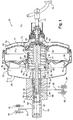
figure 1 est une vue d'ensemble en coupe axiale d'un servofrein comportant un servomoteur pneumatique d'assistance au freinage et un maître-cylindre réalisé conformément à l'invention représentés en position de repos ; - la
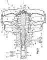
figure 2 est une vue de détail du servofrein de lafigure 1 représenté en position d'application d'un effort de freinage ; - la
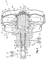
figure 3 est une vue de détail du servofrein de lafigure 1 représenté en position d'application d'un effort de freinage avec injection de liquide hydraulique dans la seconde chambre du maître-cylindre ; - la
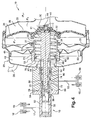
figure 4 est une vue selon lafigure 1 du servofrein représenté en position d'application d'un effort de freinage en l'absence d'assistance.
- the
figure 1 is an overall view in axial section of a booster comprising a pneumatic booster and a master cylinder made according to the invention shown in the rest position; - the
figure 2 is a detailed view of the booster of thefigure 1 shown in the application position of a braking force; - the
figure 3 is a detailed view of the booster of thefigure 1 shown in the application position of a braking force with injection of hydraulic fluid in the second chamber of the master cylinder; - the
figure 4 is a view according to thefigure 1 brake booster represented in the application position of a braking force in the absence of assistance.
Dans la description qui va suivre, des chiffres de référence identiques désignent des pièces identiques ou ayant des fonctions similaires.In the following description, like reference numerals designate like parts or having similar functions.
Par convention, les termes "avant", "arrière", supérieur", "inférieur" désignent respectivement des éléments ou des positions orientés respectivement vers la gauche, la droite, le haut, ou le bas des
On a représenté à la
De manière connue, l'agencement 10 comporte une pédale 12 de frein susceptible d'actionner un servomoteur 14 pneumatique d'assistance au freinage qui est susceptible d'actionner au moins un premier maître-cylindre 16 relié hydrauliquement à au moins un premier circuit de freinage 17 comportant un premier organe 18 de freinage du véhicule, par exemple un étrier de frein 18.In known manner, the
A cet effet, le servomoteur 14 comporte de manière connue une enveloppe 20 rigide à l'intérieur de laquelle est mobile au moins une première cloison 22 transversale qui délimite de façon étanche une première chambre avant 24 et une première chambre arrière 26.For this purpose, the servomotor 14 comprises, in known manner, a
La première chambre avant 24 est soumise à une première pression "P1", et la première chambre arrière 26 est soumise à une deuxième pression "P2" variant entre la première pression "P1" et une pression "Pa" supérieure à la première pression "P1".The first
Plus particulièrement, la pression "P1" correspond notamment à une pression fournie par une source de dépression du véhicule. Dans le cas d'un moteur à allumage commandé, la pression de dépression "P1" est par exemple fournie par un collecteur d'admission du moteur du véhicule et, dans le cas d'un moteur à allumage par compression de type "diesel", la pression de dépression "P1" est par exemple fournie par une pompe à vide du véhicule.More particularly, the pressure "P 1 " corresponds in particular to a pressure supplied by a source of depression of the vehicle. In the case of a positive ignition engine, the vacuum pressure "P 1 " is for example provided by an intake manifold of the engine of the vehicle and, in the case of a compression ignition engine of the "diesel" type ", the vacuum pressure" P 1 "is for example provided by a vacuum pump of the vehicle.
La première chambre avant 24 est reliée à la source de dépression du véhicule par l'intermédiaire d'un conduit 28 de dépression qui débouche dans l'enveloppe 20.The first
Le servomoteur 14 comporte un premier piston 30 pneumatique mobile tubulaire qui est monté coulissant et rappelé élastiquement vers l'arrière dans l'enveloppe 20 par l'intermédiaire d'un ressort de rappel 32, et dont un tronçon avant est solidaire de la première cloison 22 mobile.The servomotor 14 comprises a first tubular mobile
Le premier piston 30 est susceptible de manière connue de solliciter une tige 34 d'actionnement d'un premier piston hydraulique 36 coulissant dans une première chambre hydraulique 38 du premier maître-cylindre 16 par l'intermédiaire d'un disque 40 de réaction.The
Pour commander les mouvements de la première cloison mobile 22 et du premier piston 30, le servomoteur 14 comporte une tige 42 de commande qui est accouplée à la pédale de frein 12, qui se déplace dans le premier piston 30 pneumatique sélectivement en fonction d'un effort axial d'entrée exercé vers l'avant à l'encontre d'un effort de rappel.To control the movements of the first
Les mouvements de la tige 42 de commande sont susceptibles de déterminer les ouvertures et fermetures d'au moins un clapet axial dit "d'admission" (non représenté) qui est interposé entre une source de pression soumise à la pression "Pa" supérieure à la première pression "P1" et la première chambre arrière 26, et d'au moins un clapet axial dit "de rééquilibrage" (non représenté) qui est interposé entre la chambre première chambre avant 24 et la première chambre arrière 26, pour actionner la première cloison 22 mobile.The movements of the
Le servomoteur 14 comporte par ailleurs un plongeur 44, qui est reçu dans le premier piston 30 pneumatique tubulaire, qui traverse la première cloison 22 mobile, qui est solidaire de l'extrémité de la tige 42 de commande, et qui est susceptible de solliciter directement la tige 34 d'actionnement du premier maître-cylindre 16 par l'intermédiaire du disque 40 de réaction pour transmettre à la tige 42 de commande l'effort de réaction du fluide hydraulique contenu dans le premier organe 18 de freinage et la première chambre hydraulique 38 du maître-cylindre 16.The servomotor 14 further comprises a
Dans un tel agencement, tout effort s'exerçant sur le premier piston hydraulique 36 est retransmis à la tige de commande 42 par l'intermédiaire de la tige d'actionnement 34 et du disque 40 de réaction.In such an arrangement, any force exerted on the first
Ainsi, toute élévation de pression dans la première chambre hydraulique 38, causée par exemple par la réalimentation de ladite chambre 38 par une pompe hydraulique en réponse aux besoins d'un circuit d'anti-blocage de frein ABS, de contrôle de stabilité ESP ou d'un circuit de freinage mixte hydraulique/électrique se traduit par un effort exercé par le premier piston hydraulique 36 sur la tige d'actionnement 34, effort que le conducteur du véhicule peut donc ressentir dans la pédale 12, ce qui peut dérouter le conducteur en lui imposant une sensation de freinage à laquelle il n'est pas habitué.Thus, any increase in pressure in the first
Pour remédier à cet inconvénient, l'invention propose un agencement 10 du type décrit précédemment, caractérisé en ce que le servomoteur est susceptible d'actionner un second maître-cylindre qui est découplé mécaniquement de la tige d'actionnement 34.To remedy this drawback, the invention proposes an
Dans ce but, l'invention propose un agencement 10 du type décrit précédemment, caractérisé en ce que le servomoteur 14 comporte, en avant de la première cloison 22 une seconde cloison 46, mobile à l'intérieur de l'enveloppe 20 rigide, délimitant de façon étanche une seconde chambre avant 48, communiquant avec la première chambre avant 24, et une seconde chambre arrière 50, communiquant avec la première chambre arrière 26.For this purpose, the invention proposes an
Comme on peut le voir sur les figures, la seconde chambre arrière 50 est séparée de la première chambre avant 24 par une cloison 25 rigide.As can be seen in the figures, the second
Le servomoteur 14 comporte aussi un second piston 52 pneumatique mobile tubulaire qui est monté coulissant dans l'enveloppe 20.The servomotor 14 also comprises a second tubular mobile
Un tronçon avant 51 de ce second piston 52 pneumatique est solidaire de la seconde cloison mobile 46. Le second piston 52 est traversé coaxialement par le ressort de rappel 32 du premier piston pneumatique 30 et par la tige 34 d'actionnement du premier piston hydraulique 36. Pour garantir un guidage correct du second piston 52, un tronçon arrière 53 de celui-ci traverse aussi la cloison rigide 25. Un joint annulaire 27 assure l'étanchéité entre la cloison rigide 25 et le tronçon arrière 53.A
Le second piston pneumatique 52 est susceptible de solliciter un second piston hydraulique 54 coulissant dans une seconde chambre hydraulique 56 d'un second maître-cylindre relié à au moins à un second circuit de freinage 59 comportant un second organe 60 de freinage du véhicule.The second
Dans la configuration de repos qui a été représentée à la
Dans une configuration d'application d'un effort de freinage qui a été illustrée à la
Puis l'actionnement de la tige 42 de commande en se poursuivant provoque l'ouverture du clapet d'admission et donc l'admission d'air dans la première chambre arrière 26, et de ce fait la différence des pressions s'exerçant sur la première cloison mobile 22 provoque son avancée, celle du premier piston pneumatique 20 et par conséquent la sollicitation par le premier piston pneumatique 20 du premier piston hydraulique 36.Then actuating the
Simultanément, la seconde chambre avant 48 étant reliée à la première chambre avant 24 et la seconde chambre arrière 50 étant reliée à la première chambre arrière 26, la fermeture du clapet de rééquilibrage puis l'ouverture du clapet d'admission provoque l'avancée de la seconde cloison mobile 46, du second piston pneumatique 52 et donc la sollicitation du second piston hydraulique 54 du second maître-cylindre.Simultaneously, the second
L'avancée du second piston hydraulique 54 est donc commandée uniquement par le mouvement du second piston pneumatique 52.The advance of the second
Si le second circuit de freinage 59 comporte par exemple un circuit d'anti-blocage de frein ABS, de contrôle de stabilité ESP, ou un circuit de freinage mixte hydraulique/électrique qui est susceptible de réinjecter à l'aide d'une pompe (non représentée) du liquide hydraulique dans la seconde chambre 56 du second maître-cylindre, le servomoteur 12 peut occuper une configuration d'application d'un effort de freinage avec injection de liquide hydraulique dans la seconde chambre 56 du maître-cylindre, comme représenté à la
Dans cette configuration, l'élévation de pression dans la seconde chambre 56 provoque le recul du second piston hydraulique 54 comme représenté à la
Dans le mode de réalisation préféré de l'invention, le premier maître-cylindre 16 et le second maître-cylindre constituent un seul et même maître-cylindre 16 à chambres coaxiales 38, 56.In the preferred embodiment of the invention, the
Plus particulièrement, le maître-cylindre 16 comporte un premier corps tubulaire 62 comportant la première chambre hydraulique cylindrique 38 dans laquelle est monté coulissant le premier piston hydraulique 36. Ce premier corps 62 comporte au moins une face d'épaulement 64, qui est fixée à une face avant 66 d'un second corps coaxial 68 du maître-cylindre 16.More particularly, the
A partir de la face d'épaulement 64 s'étend au moins un tronçon arrière cylindrique 70 qui est reçu coaxialement avec jeu dans un alésage 72 du second corps 68. De la sorte, le tronçon arrière 70 et l'alésage 72 délimitent la seconde chambre hydraulique coaxiale 56 dans laquelle est monté coulissant le second piston hydraulique 54, qui est tubulaire.From the
Il sera compris que les diamètres du tronçon arrière 70 et de l'alésage 72 déterminent la surface frontale 74 du second piston hydraulique 54. Ces diamètres seront choisis pour que la surface frontale 74 soit sensiblement voisine de celle du premier piston hydraulique 36.It will be understood that the diameters of the
Avantageusement, le second piston hydraulique 54 étant coaxial au maître-cylindre 16, l'invention permet de solliciter coaxialement ledit second piston hydraulique 54 par l'intermédiaire du second piston pneumatique 52.Advantageously, the second
A cet effet, une paroi d'extrémité avant 76 du second piston pneumatique tubulaire 52 comporte au moins une partie centrale annulaire 78 d'un diamètre correspondant sensiblement à celui du second piston hydraulique 54 pour permettre la sollicitation dudit second piston hydraulique 54.For this purpose, a
Par ailleurs, la tige d'actionnement 34 comporte un tronçon avant 80 d'un diamètre correspondant à celui d'un alésage interne 82 du premier piston hydraulique 36 dans lequel elle est reçue, ce tronçon avant traversant un perçage 84 formé dans la partie centrale annulaire 78 de la paroi d'extrémité avant 76 du second piston pneumatique tubulaire 52.Furthermore, the actuating
Ainsi, comme on peut le voir sur les figures, la sollicitation des deux pistons hydrauliques 36 et 54 est elle entièrement indépendante.Thus, as can be seen in the figures, the biasing of the two
Par ailleurs, la paroi d'extrémité avant 76 du second piston pneumatique tubulaire 52 comporte au moins deux lumières axiales 85 réparties angulairement de manière régulière qui sont agencées radialement à l'extérieur de la partie centrale annulaire 78 et qui sont destinées à permettre le passage de bras 86 de maintien d'une coupelle d'appui 88 du ressort de rappel 32 du premier piston pneumatique 30, laquelle coupelle est reçue à l'intérieur de l'alésage tubulaire 90 du second piston pneumatique 52.Furthermore, the
Dans le mode de réalisation préféré de l'invention, l'agencement 10 comporte des moyens d'accouplement de la tige d'actionnement 34 du premier piston hydraulique 36 avec le second piston hydraulique 54, qui sont destinés à permettre la sollicitation du second piston hydraulique 54 par la tige d'actionnement 34 en cas de défaillance d'assistance du second piston pneumatique 52.In the preferred embodiment of the invention, the
A cet effet, la tige d'actionnement 34 comporte un tronçon arrière 91 d'un diamètre supérieur à celui du perçage 84, dont une face avant 92 est agencée selon un jeu axial "J" dit "jeu de découplage" de la paroi d'extrémité avant 76 du second piston pneumatique tubulaire 52 lorsque les pistons pneumatiques occupent leur position de repos, comme représenté à la
Ainsi, en cas de défaillance d'assistance du second piston pneumatique 52, comme représenté à la
Il sera ainsi compris que l'invention trouve essentiellement à s'appliquer à un agencement 10 dans lequel la seconde chambre hydraulique 56 du maître-cylindre 16 est reliée à au moins un second organe 60 de freinage du véhicule par l'intermédiaire d'un circuit hydraulique 59 comportant des moyens d'injection par pompage du fluide hydraulique dans ladite seconde chambre 56, ces moyens d'injection étant associés à un agencement de freinage électrique récupératif d'un véhicule hybride.It will thus be understood that the invention is essentially applicable to an
- 1010
- agencementlayout
- 1212
- pédale de freinbrake pedal
- 1414
- servomoteur pneumatique d'assistancepneumatic servo motor
- 1616
- premier maître-cylindrefirst master cylinder
- 1717
- premier circuit de freinagefirst braking circuit
- 1818
- premier organe de freinagefirst braking member
- 2020
- enveloppe du servomoteuractuator casing
- 2222
- première cloison transversale mobile du servomoteurfirst movable transverse partition of the servomotor
- 2424
- première chambre avant du servomoteurfirst front chamber of the servomotor
- 2525
- cloison séparant la seconde chambre arrière de la première chambre avantpartition separating the second rear chamber from the first front chamber
- 2626
- première chambre arrière du servomoteurfirst rear chamber of the servomotor
- 2727
- joint annulairering seal
- 2828
- conduit de dépression du servomoteurservomotor vacuum duct
- 3030
- premier piston pneumatiquefirst pneumatic piston
- 3232
- ressort de rappelspring
- 3434
- tige d'actionnementactuating rod
- 3636
- premier piston hydrauliquefirst hydraulic piston
- 3838
- première chambre hydrauliquefirst hydraulic chamber
- 4040
- disque de réactionreaction record
- 4242
- tige de commandecontrol rod
- 4444
- plongeurdiver
- 4646
- seconde cloison transversale mobile du servomoteursecond movable transverse partition of the servomotor
- 4848
- seconde chambre avant du servomoteursecond front chamber of the servomotor
- 5050
- seconde chambre arrière du servomoteursecond chamber of the servomotor
- 5151
- tronçon avant du second piston pneumatiquefront section of the second pneumatic piston
- 5252
- second piston pneumatiquesecond pneumatic piston
- 5353
- tronçon arrière du second piston pneumatiquerear section of the second pneumatic piston
- 5454
- second piston hydrauliquesecond hydraulic piston
- 5656
- seconde chambre hydrauliquesecond hydraulic chamber
- 5959
- second circuit de freinagesecond braking circuit
- 6060
- second organe de freinagesecond braking member
- 6262
- premier corps tubulaire du maître-cylindrefirst tubular body of the master cylinder
- 6363
- pompepump
- 6464
- face d'épaulement du premier corps tubulaire du maître-cylindreshoulder face of the first tubular body of the master cylinder
- 6565
- électrovanne commandéecontrolled solenoid valve
- 6666
- face avant du second corps tubulaire du maître-cylindrefront face of the second tubular body of the master cylinder
- 6767
- électronique de commandecontrol electronics
- 6868
- second corps coaxial du maître-cylindresecond coaxial body of the master cylinder
- 7070
- tronçon arrière cylindrique du premier corps tubulaire du maître-cylindrecylindrical rear section of the first tubular body of the master cylinder
- 7272
- alésage du second corps tubulaire du maître-cylindrebore of the second tubular body of the master cylinder
- 7474
- face avant du second piston hydrauliquefront side of the second hydraulic piston
- 7676
- paroi d'extrémité avant du second piston pneumatiquefront end wall of the second pneumatic piston
- 7878
- partie centrale annulaire de la paroi d'extrémité avantannular central portion of the front end wall
- 8080
- tronçon avant de la tige d'actionnementfront section of the actuating rod
- 8282
- alésage interne du premier piston hydrauliqueinternal bore of the first hydraulic piston
- 8484
- perçage de la partie centrale annulaire de la paroi d'extrémité avant du second piston pneumatiquedrilling the annular central portion of the front end wall of the second pneumatic piston
- 8585
- lumières axiales de la paroi d'extrémité avant du second piston pneumatiqueaxial lumens of the front end wall of the second pneumatic piston
- 8686
- brasarms
- 8888
- coupelle d'appuicup of support
- 9090
- alésage du second piston pneumatiquebore of the second pneumatic piston
- 9191
- tronçon arrière de la tige d'actionnementrear section of the actuating rod
- 9292
- face avant du tronçon arrière de la tige d'actionnement.front face of the rear section of the actuating rod.
Claims (7)
- Braking control arrangement (10) for a motor vehicle, comprising a brake pedal (12) capable of actuating a pneumatic brake booster (14) of at least a first master cylinder (16) connected hydraulically to at least a first braking member (18) of the vehicle,
the said booster (14) comprising a rigid envelope (20) inside which there can move at least a first transverse partition (22) delimiting in a sealed manner a first front chamber (24), subjected to a first pressure (P1), and a first rear chamber (26), subjected to a second pressure (P2) varying between the first pressure (P1) and a pressure (Pa) greater than the first pressure (P1),
the said booster (14) comprising a first tubular movable pneumatic piston (30) which is mounted slideably and returned elastically towards the rear inside the envelope (20) via a return spring (32), of which a front portion is secured to the first movable partition (22), and which is capable of acting on a rod (34) for actuating a first hydraulic piston (36) sliding in a first hydraulic chamber (38) of the first master cylinder (16) via a reaction disc (40),
the said booster (14) comprising a control rod (42) coupled to the brake pedal (12) and moving in the first pneumatic piston (30) selectively as a function of an axial input force exerted towards the front against a return force,
the movements of the said control rod (42) being capable of determining the openings and closings of at least one axial valve, termed "intake" valve, which is interposed between a pressure source subjected to the pressure (Pa) greater than the first pressure (P1) and the first rear chamber (26), and of at least one axial valve, termed "equalizing" valve, which is interposed between the first front chamber (24) and the first rear chamber (26), in order to actuate the first movable partition (22),
the said booster comprising a plunger (44), which is received in the first tubular pneumatic piston (30), which traverses the first movable partition (22), which is secured to the end of the control rod (42), and which is capable of acting directly on the actuating rod (34) of the first master cylinder (16) via the reaction disc (40) in order to transmit to the control rod (42) the reaction force of the hydraulic fluid contained in the first braking member (18) and the first hydraulic chamber (38) of the master cylinder (16), characterized in that the booster (14) comprises, in front of the first partition (22):- a second partition (46), movable inside the rigid envelope (20), delimiting in a sealed manner a second front chamber (48), communicating with the first front chamber (24), and a second rear chamber (50), communicating with the first rear chamber (26), the second rear chamber (50) being separated from the first front chamber (24) by a rigid partition (25),- a second tubular movable pneumatic piston (52) which is mounted slideably in the envelope (20), which is traversed coaxially by the return spring (32) of the first pneumatic piston (30) and by the rod (34) for actuating the first hydraulic piston (36), and of which a front portion (51) is secured to the second movable partition (46),the said second pneumatic piston (52) being coupled to a second hydraulic piston (54) sliding in a second hydraulic chamber (56) of a second master cylinder connected to at least a second braking member (60) of the vehicle, in order to make it possible to actuate the said second hydraulic piston (54) without the reaction force of the hydraulic fluid contained in the second braking member (60) and the second hydraulic chamber (56) of the second master cylinder being transmitted to the control rod (42). - Arrangement (10) according to the preceding claim, characterized in that the first (16) and second master cylinders constitute one and the same master cylinder (16) with coaxial chambers (38, 56).
- Arrangement (10) according to the preceding claim, characterized in that the master cylinder (16) comprises a first tubular body (62) comprising the first cylindrical hydraulic chamber (38) in which the first hydraulic piston (36) is slideably mounted, and in that the said first body (62) comprises at least one shoulder face (64), which is fixed to a front face (66) of a second coaxial body (68) of the master cylinder (16), and from which there extends at least one cylindrical rear portion (70) which is received coaxially with play in a bore (72) of the second body (68) in order to delimit the second coaxial hydraulic chamber (56) in which the second tubular hydraulic piston (54) is slideably mounted.
- Arrangement (10) according to one of the preceding claims, characterized in that it comprises means for coupling the rod (34) for actuating the first hydraulic piston (36) with the second hydraulic piston (54), which are intended to allow the second hydraulic piston (54) to be acted on by the actuating rod (34) in the event of assistance failure of the second pneumatic piston (52).
- Arrangement (10) according to the preceding claim, characterized in that the actuating rod (34) comprises:- a front portion (80) with a diameter corresponding to that of an internal bore (82) of the first hydraulic piston (36), which traverses a perforation (84) in a front end wall (76) of the second tubular pneumatic piston (52),- a rear portion (91) with a diameter greater than that of the said perforation (84), of which a front face (92) is arranged with an axial play (J), termed "decoupling play", from the said front end wall (76) of the second tubular pneumatic piston (52) when the pneumatic pistons (30, 52) occupy their rest position, in order to allow the actuating rod (34) to act on the second hydraulic piston (54) via the front end wall (76) of the second pneumatic piston (52) in the event of assistance failure of the said second pneumatic piston (52).
- Arrangement (10) according to the preceding claim, characterized in that the front end wall (76) of the second tubular pneumatic piston (52) comprises:- at least one annular central part (78) with a diameter corresponding substantially to that of the second hydraulic piston (54) in order to allow the said second hydraulic piston (54) to be acted on, the said central part (78) being traversed by the perforation (84) for the passage of the actuating rod (34),- at least two axial slots (85) distributed angularly in a regular manner, which are arranged radially outside the said annular central part (78) and which are intended to allow the passage of arms (86) for retaining a bearing cup (88) for the return spring (32) of the first pneumatic piston (30), which cup is received inside the tubular bore (90) of the second pneumatic piston (52).
- Arrangement (10) according to any one of the preceding claims, characterized in that the second hydraulic chamber (56) of the second master cylinder is connected to at least a second braking member (60) of the vehicle via a hydraulic circuit (59) comprising means for injecting the hydraulic fluid into the said second chamber (56) by pumping, these injection means being associated with a regenerative electric braking arrangement of a hybrid vehicle.
Applications Claiming Priority (2)
| Application Number | Priority Date | Filing Date | Title |
|---|---|---|---|
| FR1001977A FR2959715B1 (en) | 2010-05-07 | 2010-05-07 | BRAKE CONTROL ARRANGEMENT COMPRISING A PARTLY DISPENSED SERVOFREIN |
| PCT/EP2011/053512 WO2011138066A1 (en) | 2010-05-07 | 2011-03-09 | Brake operating arrangement comprising a partially uncoupled brake servo |
Publications (2)
| Publication Number | Publication Date |
|---|---|
| EP2566732A1 EP2566732A1 (en) | 2013-03-13 |
| EP2566732B1 true EP2566732B1 (en) | 2016-01-20 |
Family
ID=43365827
Family Applications (1)
| Application Number | Title | Priority Date | Filing Date |
|---|---|---|---|
| EP11707410.4A Not-in-force EP2566732B1 (en) | 2010-05-07 | 2011-03-09 | Brake operating arrangement comprising a partially uncoupled brake servo |
Country Status (3)
| Country | Link |
|---|---|
| EP (1) | EP2566732B1 (en) |
| FR (1) | FR2959715B1 (en) |
| WO (1) | WO2011138066A1 (en) |
Family Cites Families (2)
| Publication number | Priority date | Publication date | Assignee | Title |
|---|---|---|---|---|
| DE4116372A1 (en) * | 1991-05-18 | 1992-11-19 | Teves Gmbh Alfred | Function mass adjuster for booster of vehicle hydraulic brake - uses axially displaceable ring working with collar |
| KR20070006738A (en) * | 2004-02-02 | 2007-01-11 | 루카스 오토모티브 게엠베하 | Braking force generator for a hydraulic vehicle braking system |
-
2010
- 2010-05-07 FR FR1001977A patent/FR2959715B1/en not_active Expired - Fee Related
-
2011
- 2011-03-09 EP EP11707410.4A patent/EP2566732B1/en not_active Not-in-force
- 2011-03-09 WO PCT/EP2011/053512 patent/WO2011138066A1/en active Application Filing
Also Published As
| Publication number | Publication date |
|---|---|
| EP2566732A1 (en) | 2013-03-13 |
| FR2959715A1 (en) | 2011-11-11 |
| FR2959715B1 (en) | 2012-06-15 |
| WO2011138066A1 (en) | 2011-11-10 |
Similar Documents
| Publication | Publication Date | Title |
|---|---|---|
| EP2437963B1 (en) | Brake system having a master cylinder that is decoupled from the brake pedal and hydraulic brake booster | |
| EP1636077B1 (en) | Servo motor with reduced slack and brake system comprising such a servo motor | |
| EP0779868B1 (en) | Protected-travel improved-safety power-assisted brake device | |
| EP1457400A1 (en) | Hydraulic brake device with improved braking sensitivity | |
| EP0993398B1 (en) | Improved master cylinder with hydraulic reaction capable of being cancelled | |
| EP2566732B1 (en) | Brake operating arrangement comprising a partially uncoupled brake servo | |
| EP0993399B1 (en) | Master cylinder with dynamic hydraulic reaction and floating piston | |
| EP0687229B1 (en) | Power braking device with simplified automatic control | |
| EP0991555B1 (en) | Master cylinder with hydraulic reaction set by a difference of sections | |
| FR2853610A1 (en) | BRAKE PNEUMATIC ASSISTANCE ACTUATOR WITH REDUCED OPERATING NOISE | |
| FR2812257A1 (en) | SERVOMOTOR FOR EMERGENCY BRAKING INCLUDING MEANS OF SOUNDPROOFING | |
| FR2967957A1 (en) | Brake control arrangement for motor vehicle, has three-way solenoid valve establishing communication between chambers so as to cause downward movement of hydraulic piston and secondary suction of hydraulic fluid in hydraulic chamber | |
| EP1325853B1 (en) | Pneumatic brake servo with reduced reaction | |
| EP1564098B1 (en) | Brake system including a master cylinder and a double vacuum booster | |
| EP1124716B1 (en) | Master cylinder with dynamically adjustable hydraulic reaction | |
| EP0368701B1 (en) | Hydraulic servo brake system, and brake booster and control valve suitable for such a system | |
| FR2882318A1 (en) | PNEUMATIC ASSISTANCE ASSISTOR FOR REDUCED DEAD STROKE BRAKING AND BRAKE MASTER FOR SUCH A SERVOMOTOR | |
| FR2629033A1 (en) | Hydraulic brake servomotor with remote control from pedal - has master cylinder providing auxiliary circuit which opens servo control valve to initiate braking assistance | |
| FR2967386A1 (en) | Brake control arrangement for motor vehicle, has rapid rebalancing valve arranged inside rigid envelope and allowing vacuum chamber to directly communicate with work chamber without passing through outer pneumatic circuit | |
| FR2778616A1 (en) | Reaction master cylinder for hydraulic braking systems | |
| WO2002094626A1 (en) | Pneumatic servo brake booster with variable jump | |
| FR2727370A1 (en) | Braking system with hydraulic servo assisted unit for vehicle | |
| FR2765171A1 (en) | Power assisted braking system master cylinder with hydraulic reaction, used for vehicles | |
| FR2737456A1 (en) | Pneumatic assisted hydraulic braking system for motor vehicle - has pressure from master cylinder controlling auxiliary valve to connect working chamber of pneumatic servo-motor selectively to vacuum or to atmosphere | |
| FR2638789A1 (en) | Device for controlling a booster, particularly for a motor vehicle braking system |
Legal Events
| Date | Code | Title | Description |
|---|---|---|---|
| PUAI | Public reference made under article 153(3) epc to a published international application that has entered the european phase |
Free format text: ORIGINAL CODE: 0009012 |
|
| 17P | Request for examination filed |
Effective date: 20121207 |
|
| AK | Designated contracting states |
Kind code of ref document: A1 Designated state(s): AL AT BE BG CH CY CZ DE DK EE ES FI FR GB GR HR HU IE IS IT LI LT LU LV MC MK MT NL NO PL PT RO RS SE SI SK SM TR |
|
| DAX | Request for extension of the european patent (deleted) | ||
| GRAP | Despatch of communication of intention to grant a patent |
Free format text: ORIGINAL CODE: EPIDOSNIGR1 |
|
| INTG | Intention to grant announced |
Effective date: 20151007 |
|
| GRAS | Grant fee paid |
Free format text: ORIGINAL CODE: EPIDOSNIGR3 |
|
| GRAA | (expected) grant |
Free format text: ORIGINAL CODE: 0009210 |
|
| AK | Designated contracting states |
Kind code of ref document: B1 Designated state(s): AL AT BE BG CH CY CZ DE DK EE ES FI FR GB GR HR HU IE IS IT LI LT LU LV MC MK MT NL NO PL PT RO RS SE SI SK SM TR |
|
| REG | Reference to a national code |
Ref country code: GB Ref legal event code: FG4D Free format text: NOT ENGLISH |
|
| REG | Reference to a national code |
Ref country code: CH Ref legal event code: EP |
|
| REG | Reference to a national code |
Ref country code: IE Ref legal event code: FG4D Free format text: LANGUAGE OF EP DOCUMENT: FRENCH |
|
| REG | Reference to a national code |
Ref country code: AT Ref legal event code: REF Ref document number: 771559 Country of ref document: AT Kind code of ref document: T Effective date: 20160215 |
|
| REG | Reference to a national code |
Ref country code: DE Ref legal event code: R096 Ref document number: 602011022799 Country of ref document: DE |
|
| REG | Reference to a national code |
Ref country code: FR Ref legal event code: PLFP Year of fee payment: 6 |
|
| REG | Reference to a national code |
Ref country code: LT Ref legal event code: MG4D Ref country code: NL Ref legal event code: MP Effective date: 20160120 |
|
| REG | Reference to a national code |
Ref country code: AT Ref legal event code: MK05 Ref document number: 771559 Country of ref document: AT Kind code of ref document: T Effective date: 20160120 |
|
| PG25 | Lapsed in a contracting state [announced via postgrant information from national office to epo] |
Ref country code: NL Free format text: LAPSE BECAUSE OF FAILURE TO SUBMIT A TRANSLATION OF THE DESCRIPTION OR TO PAY THE FEE WITHIN THE PRESCRIBED TIME-LIMIT Effective date: 20160120 |
|
| PG25 | Lapsed in a contracting state [announced via postgrant information from national office to epo] |
Ref country code: NO Free format text: LAPSE BECAUSE OF FAILURE TO SUBMIT A TRANSLATION OF THE DESCRIPTION OR TO PAY THE FEE WITHIN THE PRESCRIBED TIME-LIMIT Effective date: 20160420 Ref country code: IT Free format text: LAPSE BECAUSE OF FAILURE TO SUBMIT A TRANSLATION OF THE DESCRIPTION OR TO PAY THE FEE WITHIN THE PRESCRIBED TIME-LIMIT Effective date: 20160120 Ref country code: GR Free format text: LAPSE BECAUSE OF FAILURE TO SUBMIT A TRANSLATION OF THE DESCRIPTION OR TO PAY THE FEE WITHIN THE PRESCRIBED TIME-LIMIT Effective date: 20160421 Ref country code: HR Free format text: LAPSE BECAUSE OF FAILURE TO SUBMIT A TRANSLATION OF THE DESCRIPTION OR TO PAY THE FEE WITHIN THE PRESCRIBED TIME-LIMIT Effective date: 20160120 Ref country code: FI Free format text: LAPSE BECAUSE OF FAILURE TO SUBMIT A TRANSLATION OF THE DESCRIPTION OR TO PAY THE FEE WITHIN THE PRESCRIBED TIME-LIMIT Effective date: 20160120 Ref country code: ES Free format text: LAPSE BECAUSE OF FAILURE TO SUBMIT A TRANSLATION OF THE DESCRIPTION OR TO PAY THE FEE WITHIN THE PRESCRIBED TIME-LIMIT Effective date: 20160120 |
|
| PG25 | Lapsed in a contracting state [announced via postgrant information from national office to epo] |
Ref country code: IS Free format text: LAPSE BECAUSE OF FAILURE TO SUBMIT A TRANSLATION OF THE DESCRIPTION OR TO PAY THE FEE WITHIN THE PRESCRIBED TIME-LIMIT Effective date: 20160520 Ref country code: RS Free format text: LAPSE BECAUSE OF FAILURE TO SUBMIT A TRANSLATION OF THE DESCRIPTION OR TO PAY THE FEE WITHIN THE PRESCRIBED TIME-LIMIT Effective date: 20160120 Ref country code: AT Free format text: LAPSE BECAUSE OF FAILURE TO SUBMIT A TRANSLATION OF THE DESCRIPTION OR TO PAY THE FEE WITHIN THE PRESCRIBED TIME-LIMIT Effective date: 20160120 Ref country code: PT Free format text: LAPSE BECAUSE OF FAILURE TO SUBMIT A TRANSLATION OF THE DESCRIPTION OR TO PAY THE FEE WITHIN THE PRESCRIBED TIME-LIMIT Effective date: 20160520 Ref country code: LT Free format text: LAPSE BECAUSE OF FAILURE TO SUBMIT A TRANSLATION OF THE DESCRIPTION OR TO PAY THE FEE WITHIN THE PRESCRIBED TIME-LIMIT Effective date: 20160120 Ref country code: PL Free format text: LAPSE BECAUSE OF FAILURE TO SUBMIT A TRANSLATION OF THE DESCRIPTION OR TO PAY THE FEE WITHIN THE PRESCRIBED TIME-LIMIT Effective date: 20160120 Ref country code: BE Free format text: LAPSE BECAUSE OF NON-PAYMENT OF DUE FEES Effective date: 20160331 Ref country code: SE Free format text: LAPSE BECAUSE OF FAILURE TO SUBMIT A TRANSLATION OF THE DESCRIPTION OR TO PAY THE FEE WITHIN THE PRESCRIBED TIME-LIMIT Effective date: 20160120 Ref country code: LV Free format text: LAPSE BECAUSE OF FAILURE TO SUBMIT A TRANSLATION OF THE DESCRIPTION OR TO PAY THE FEE WITHIN THE PRESCRIBED TIME-LIMIT Effective date: 20160120 |
|
| REG | Reference to a national code |
Ref country code: DE Ref legal event code: R097 Ref document number: 602011022799 Country of ref document: DE |
|
| PG25 | Lapsed in a contracting state [announced via postgrant information from national office to epo] |
Ref country code: LU Free format text: LAPSE BECAUSE OF FAILURE TO SUBMIT A TRANSLATION OF THE DESCRIPTION OR TO PAY THE FEE WITHIN THE PRESCRIBED TIME-LIMIT Effective date: 20160309 Ref country code: EE Free format text: LAPSE BECAUSE OF FAILURE TO SUBMIT A TRANSLATION OF THE DESCRIPTION OR TO PAY THE FEE WITHIN THE PRESCRIBED TIME-LIMIT Effective date: 20160120 Ref country code: MC Free format text: LAPSE BECAUSE OF FAILURE TO SUBMIT A TRANSLATION OF THE DESCRIPTION OR TO PAY THE FEE WITHIN THE PRESCRIBED TIME-LIMIT Effective date: 20160120 Ref country code: DK Free format text: LAPSE BECAUSE OF FAILURE TO SUBMIT A TRANSLATION OF THE DESCRIPTION OR TO PAY THE FEE WITHIN THE PRESCRIBED TIME-LIMIT Effective date: 20160120 |
|
| REG | Reference to a national code |
Ref country code: CH Ref legal event code: PL |
|
| PLBE | No opposition filed within time limit |
Free format text: ORIGINAL CODE: 0009261 |
|
| STAA | Information on the status of an ep patent application or granted ep patent |
Free format text: STATUS: NO OPPOSITION FILED WITHIN TIME LIMIT |
|
| PG25 | Lapsed in a contracting state [announced via postgrant information from national office to epo] |
Ref country code: SM Free format text: LAPSE BECAUSE OF FAILURE TO SUBMIT A TRANSLATION OF THE DESCRIPTION OR TO PAY THE FEE WITHIN THE PRESCRIBED TIME-LIMIT Effective date: 20160120 Ref country code: CZ Free format text: LAPSE BECAUSE OF FAILURE TO SUBMIT A TRANSLATION OF THE DESCRIPTION OR TO PAY THE FEE WITHIN THE PRESCRIBED TIME-LIMIT Effective date: 20160120 Ref country code: RO Free format text: LAPSE BECAUSE OF FAILURE TO SUBMIT A TRANSLATION OF THE DESCRIPTION OR TO PAY THE FEE WITHIN THE PRESCRIBED TIME-LIMIT Effective date: 20160120 Ref country code: SK Free format text: LAPSE BECAUSE OF FAILURE TO SUBMIT A TRANSLATION OF THE DESCRIPTION OR TO PAY THE FEE WITHIN THE PRESCRIBED TIME-LIMIT Effective date: 20160120 |
|
| 26N | No opposition filed |
Effective date: 20161021 |
|
| GBPC | Gb: european patent ceased through non-payment of renewal fee |
Effective date: 20160420 |
|
| REG | Reference to a national code |
Ref country code: IE Ref legal event code: MM4A |
|
| PG25 | Lapsed in a contracting state [announced via postgrant information from national office to epo] |
Ref country code: GB Free format text: LAPSE BECAUSE OF NON-PAYMENT OF DUE FEES Effective date: 20160420 Ref country code: LI Free format text: LAPSE BECAUSE OF NON-PAYMENT OF DUE FEES Effective date: 20160331 Ref country code: CH Free format text: LAPSE BECAUSE OF NON-PAYMENT OF DUE FEES Effective date: 20160331 Ref country code: IE Free format text: LAPSE BECAUSE OF NON-PAYMENT OF DUE FEES Effective date: 20160309 |
|
| PG25 | Lapsed in a contracting state [announced via postgrant information from national office to epo] |
Ref country code: BG Free format text: LAPSE BECAUSE OF FAILURE TO SUBMIT A TRANSLATION OF THE DESCRIPTION OR TO PAY THE FEE WITHIN THE PRESCRIBED TIME-LIMIT Effective date: 20160420 Ref country code: SI Free format text: LAPSE BECAUSE OF FAILURE TO SUBMIT A TRANSLATION OF THE DESCRIPTION OR TO PAY THE FEE WITHIN THE PRESCRIBED TIME-LIMIT Effective date: 20160120 |
|
| REG | Reference to a national code |
Ref country code: FR Ref legal event code: PLFP Year of fee payment: 7 |
|
| PGFP | Annual fee paid to national office [announced via postgrant information from national office to epo] |
Ref country code: FR Payment date: 20170323 Year of fee payment: 7 |
|
| PGFP | Annual fee paid to national office [announced via postgrant information from national office to epo] |
Ref country code: DE Payment date: 20170529 Year of fee payment: 7 |
|
| PG25 | Lapsed in a contracting state [announced via postgrant information from national office to epo] |
Ref country code: MT Free format text: LAPSE BECAUSE OF FAILURE TO SUBMIT A TRANSLATION OF THE DESCRIPTION OR TO PAY THE FEE WITHIN THE PRESCRIBED TIME-LIMIT Effective date: 20160120 |
|
| PG25 | Lapsed in a contracting state [announced via postgrant information from national office to epo] |
Ref country code: CY Free format text: LAPSE BECAUSE OF FAILURE TO SUBMIT A TRANSLATION OF THE DESCRIPTION OR TO PAY THE FEE WITHIN THE PRESCRIBED TIME-LIMIT Effective date: 20160120 Ref country code: HU Free format text: LAPSE BECAUSE OF FAILURE TO SUBMIT A TRANSLATION OF THE DESCRIPTION OR TO PAY THE FEE WITHIN THE PRESCRIBED TIME-LIMIT; INVALID AB INITIO Effective date: 20110309 |
|
| PG25 | Lapsed in a contracting state [announced via postgrant information from national office to epo] |
Ref country code: MK Free format text: LAPSE BECAUSE OF FAILURE TO SUBMIT A TRANSLATION OF THE DESCRIPTION OR TO PAY THE FEE WITHIN THE PRESCRIBED TIME-LIMIT Effective date: 20160120 Ref country code: TR Free format text: LAPSE BECAUSE OF FAILURE TO SUBMIT A TRANSLATION OF THE DESCRIPTION OR TO PAY THE FEE WITHIN THE PRESCRIBED TIME-LIMIT Effective date: 20160120 |
|
| REG | Reference to a national code |
Ref country code: DE Ref legal event code: R119 Ref document number: 602011022799 Country of ref document: DE |
|
| PG25 | Lapsed in a contracting state [announced via postgrant information from national office to epo] |
Ref country code: AL Free format text: LAPSE BECAUSE OF FAILURE TO SUBMIT A TRANSLATION OF THE DESCRIPTION OR TO PAY THE FEE WITHIN THE PRESCRIBED TIME-LIMIT Effective date: 20160120 |
|
| PG25 | Lapsed in a contracting state [announced via postgrant information from national office to epo] |
Ref country code: DE Free format text: LAPSE BECAUSE OF NON-PAYMENT OF DUE FEES Effective date: 20181002 |
|
| PG25 | Lapsed in a contracting state [announced via postgrant information from national office to epo] |
Ref country code: FR Free format text: LAPSE BECAUSE OF NON-PAYMENT OF DUE FEES Effective date: 20180331 |