EP2565633B1 - Method for determining softening or dropping point - Google Patents
Method for determining softening or dropping point Download PDFInfo
- Publication number
- EP2565633B1 EP2565633B1 EP11179996.1A EP11179996A EP2565633B1 EP 2565633 B1 EP2565633 B1 EP 2565633B1 EP 11179996 A EP11179996 A EP 11179996A EP 2565633 B1 EP2565633 B1 EP 2565633B1
- Authority
- EP
- European Patent Office
- Prior art keywords
- sample
- image
- temperature
- sample chamber
- time data
- Prior art date
- Legal status (The legal status is an assumption and is not a legal conclusion. Google has not performed a legal analysis and makes no representation as to the accuracy of the status listed.)
- Active
Links
- 238000000034 method Methods 0.000 title claims description 42
- 239000000126 substance Substances 0.000 claims description 65
- 238000005259 measurement Methods 0.000 claims description 35
- 230000008859 change Effects 0.000 claims description 29
- 238000010438 heat treatment Methods 0.000 claims description 21
- 238000011156 evaluation Methods 0.000 claims description 12
- 230000006870 function Effects 0.000 claims description 9
- 230000015572 biosynthetic process Effects 0.000 claims description 8
- 230000006399 behavior Effects 0.000 claims description 5
- 238000001816 cooling Methods 0.000 claims description 4
- 238000001228 spectrum Methods 0.000 claims description 3
- 238000001454 recorded image Methods 0.000 claims 4
- 230000000007 visual effect Effects 0.000 claims 2
- 239000000523 sample Substances 0.000 description 167
- 230000002123 temporal effect Effects 0.000 description 15
- 238000001514 detection method Methods 0.000 description 9
- 239000007788 liquid Substances 0.000 description 6
- 239000007787 solid Substances 0.000 description 6
- 239000010426 asphalt Substances 0.000 description 5
- 238000002844 melting Methods 0.000 description 5
- 230000008018 melting Effects 0.000 description 5
- 239000003086 colorant Substances 0.000 description 4
- 230000007704 transition Effects 0.000 description 4
- 230000003287 optical effect Effects 0.000 description 3
- 238000004458 analytical method Methods 0.000 description 2
- 230000004888 barrier function Effects 0.000 description 2
- 238000012512 characterization method Methods 0.000 description 2
- 238000009413 insulation Methods 0.000 description 2
- 239000003921 oil Substances 0.000 description 2
- 229920000642 polymer Polymers 0.000 description 2
- 238000003908 quality control method Methods 0.000 description 2
- 230000008023 solidification Effects 0.000 description 2
- 238000007711 solidification Methods 0.000 description 2
- 239000001993 wax Substances 0.000 description 2
- 240000006829 Ficus sundaica Species 0.000 description 1
- 229910000831 Steel Inorganic materials 0.000 description 1
- 230000008901 benefit Effects 0.000 description 1
- 239000011230 binding agent Substances 0.000 description 1
- 230000000052 comparative effect Effects 0.000 description 1
- 238000000354 decomposition reaction Methods 0.000 description 1
- 230000007423 decrease Effects 0.000 description 1
- 230000001419 dependent effect Effects 0.000 description 1
- 239000008157 edible vegetable oil Substances 0.000 description 1
- 238000002474 experimental method Methods 0.000 description 1
- 239000003925 fat Substances 0.000 description 1
- 238000010191 image analysis Methods 0.000 description 1
- 238000003780 insertion Methods 0.000 description 1
- 230000037431 insertion Effects 0.000 description 1
- 230000001050 lubricating effect Effects 0.000 description 1
- 239000000463 material Substances 0.000 description 1
- 239000002184 metal Substances 0.000 description 1
- 239000000203 mixture Substances 0.000 description 1
- 238000010422 painting Methods 0.000 description 1
- 239000011295 pitch Substances 0.000 description 1
- 229920000098 polyolefin Polymers 0.000 description 1
- 239000000843 powder Substances 0.000 description 1
- 238000012545 processing Methods 0.000 description 1
- 238000000275 quality assurance Methods 0.000 description 1
- 229920005989 resin Polymers 0.000 description 1
- 239000011347 resin Substances 0.000 description 1
- 238000005070 sampling Methods 0.000 description 1
- 239000004065 semiconductor Substances 0.000 description 1
- 239000000344 soap Substances 0.000 description 1
- 239000010959 steel Substances 0.000 description 1
- 238000012360 testing method Methods 0.000 description 1
- 229940099259 vaseline Drugs 0.000 description 1
- XLYOFNOQVPJJNP-UHFFFAOYSA-N water Substances O XLYOFNOQVPJJNP-UHFFFAOYSA-N 0.000 description 1
Images


Classifications
-
- G—PHYSICS
- G01—MEASURING; TESTING
- G01N—INVESTIGATING OR ANALYSING MATERIALS BY DETERMINING THEIR CHEMICAL OR PHYSICAL PROPERTIES
- G01N25/00—Investigating or analyzing materials by the use of thermal means
- G01N25/02—Investigating or analyzing materials by the use of thermal means by investigating changes of state or changes of phase; by investigating sintering
- G01N25/04—Investigating or analyzing materials by the use of thermal means by investigating changes of state or changes of phase; by investigating sintering of melting point; of freezing point; of softening point
-
- G—PHYSICS
- G01—MEASURING; TESTING
- G01N—INVESTIGATING OR ANALYSING MATERIALS BY DETERMINING THEIR CHEMICAL OR PHYSICAL PROPERTIES
- G01N33/00—Investigating or analysing materials by specific methods not covered by groups G01N1/00 - G01N31/00
- G01N33/42—Road-making materials
-
- G—PHYSICS
- G01—MEASURING; TESTING
- G01K—MEASURING TEMPERATURE; MEASURING QUANTITY OF HEAT; THERMALLY-SENSITIVE ELEMENTS NOT OTHERWISE PROVIDED FOR
- G01K11/00—Measuring temperature based upon physical or chemical changes not covered by groups G01K3/00, G01K5/00, G01K7/00 or G01K9/00
- G01K11/06—Measuring temperature based upon physical or chemical changes not covered by groups G01K3/00, G01K5/00, G01K7/00 or G01K9/00 using melting, freezing, or softening
Definitions
- the invention relates to a method for determining the softening or drip point of a substance, and more particularly to an automated method.
- the determination of the softening or dripping point is a generally accepted method for determining characteristic properties of a substance or a substance.
- US 3,587,293A discloses that the determination of the softening point is particularly relevant for substances which do not have a sharp phase transition between solid and liquid.
- the drop point is the temperature at which a substance begins to flow under predetermined and often standardized test conditions.
- the substance is heated until it changes from the solid to the liquid state. During the measurement, the temperature is detected at which a first drop of the substance dissolves.
- the dropping point determination can be carried out according to one of the common standards, such as ASTM D3954, Ph. Eur. 2.2.17 (Pharmacopoea Europaea) or AOCS Cc 18-18 (American Oil Chemists' Society).
- ASTM D3954 Ph. Eur. 2.2.17 (Pharmacopoea Europaea) or AOCS Cc 18-18 (American Oil Chemists' Society).
- polymers raw polymer, waxes, polyolefins, paraffins, lubricating greases, organic powders, vaseline, edible fats, edible oils and related substances, these are used for characterization and also for quality control.
- the softening point is a measurement for classifying bitumen and bituminous substances, for example.
- the softening point can be determined by means of a ring-and-ball method, as described, for example, in US Pat US 3,242,277 A is described. In determining this value, a steel ball is placed on a bitumen or bitumen sample placed in a ring. In the course of the experiment, the material is heated evenly and the corresponding temperature is recorded as the softening point, at which the sample has bent down by 25.4 ⁇ 0.2 millimeters. Furthermore, the softening point can be determined by determining the temperature at which an expanding drop has reached a certain length. The drop formation from the The substance to be analyzed is caused by heating.
- the softening point can be determined according to one of the common standards, such as ASTM D3104, D3461 and D6090 and DIN 51920. The determination of the softening point is also used for quality control and characterization of bitumen, pitch, asphalt, resins, binders and related substances.
- GB 2464717 A discloses, for example, a device for optically detecting the melting point, in which a sample in a melting-point tube is visually detected on heating and this data is evaluated to determine the melting point.
- the melting point signifies the temperature of the phase transition solid to liquid and can be followed visually well, since a solid sample is usually opaque and a liquid sample is often transparent, so that reaching an intensity maximum with the achievement of the melting point can be substantially equated.
- US 2009/0190626 A1 discloses an apparatus for optically detecting the melting point and other phase transitions of one or more substances disposed in the wells of a flat carrier. Above all, comparative values for different substances and less absolute values for the phase transitions can be detected with this device.
- the sample or substance to be analyzed may be liquid or solid and include an intermediate state.
- the substance can be described as liquid, solid, waxy, bituminous, viscous or pulverulent.
- measuring devices are known with which either the softening point or the dropping point can be determined.
- the determinations are often made in measuring instruments with a heatable sample chamber.
- the substance to be analyzed is filled into a suitable sample vessel and this is introduced into the sample chamber, in which the sample, in particular the substance in the sample vessel, is subsequently heated.
- the reaching of the softening point is determined when the first drop of the substance reaches a predetermined length and breaks through, for example, a correspondingly arranged light barrier.
- the temperature at this time is registered as a softening point.
- JP 58062551 A discloses a device for the optical determination of the softening point, in which the shadow of the drop is detected and whose length is evaluated.
- the measuring chambers of known measuring devices are usually closed and can not be viewed directly. This is mainly used to avoid cold spots on a window and thus the uniform heating of the sample. In other known measuring devices oil or water baths are used to heat the sample.
- the meter includes a Sample chamber, a temperature sensor, a heater, means for providing temperature-time setpoints, means for image acquisition, in particular a means for digital image capture, and a control unit with a processor unit.
- the heater is used to heat the sample chamber based on predetermined temperatures, such as the temperature-time setpoints. With the temperature sensor, the temperature can be detected inside the sample chamber and with the means for image acquisition, the interior of the sample chamber can be visually detected.
- the inventive method comprises several steps. First, a sample vessel with a sample of the substance to be analyzed is prepared and introduced into the sample chamber. Furthermore, temperature-time setpoints are provided. In the sample chamber, a predetermined starting temperature is set, and then the sample chamber is heated according to the predetermined temperature-time setpoints. During the measurement, temperature-time actual values are determined in the sample chamber with the temperature sensor and, in addition, image-time data from the interior of the sample chamber are recorded with the means for image acquisition. On the basis of the acquired image-time data and temperature-time actual values, a temporal change of the sample as a function of the temperature can be determined.
- the temporal change of the sample comprises formation of at least one drop and its change in length or tearing due to a softening of the sample by the heat input of the heating device (11), which is reproduced in the image-time data.
- the temporal change of the sample as a function of the temperature of its drip or softening point can be determined.
- the evaluation of the recorded temperature actual values and image time data enables the detection of the dripping or softening point of the substance.
- the image acquisition also allows optical control of the substance during the heating process, whereby the reproducibility of the measurement results can be increased, since measurement errors due to atypical behaving samples can be easily recognized.
- measurement errors can occur, for example, if, during the determination of the softening point, the resulting drop breaks off before it reaches the predetermined length or does not even reach it, or if drops of very different size, shape or color are formed during the drop point determination, which may indicate that the sample heats up unevenly, or that the heat spreads unevenly in the sample.
- the reproducibility of the measurements can be increased by visually and / or visually observing the different behavior of at least two identical samples and thus detecting deviations between the actually identical samples.
- the inventive method also includes a step of color and / or white balance which serves to adjust and / or adjust the color spectrum of the means for image capture or the image acquisition means.
- a step of color and / or white balance which serves to adjust and / or adjust the color spectrum of the means for image capture or the image acquisition means.
- an area with a defined color, preferably white can be arranged in the sample chamber. This area is detected prior to the introduction of the samples, and the means for image acquisition is set such that the captured image of that area corresponds to a given color, for example R 100 G 100 B 100 of the RGB color scheme or another defined color.
- the color and / or white balance allows the acquisition of comparable image-time data, which are comparable in particular due to the colors shown. In this way, color differences between the samples can be detected, for example, in series measurements, which may be advantageous for the user, since different colors may indicate a different composition of the substance to be analyzed or even a decomposition of the substance.
- the inventive method also includes a brightness balance, which is to ensure that the image-time data are detected at substantially the same brightness ratios. In this way, the reproducibility of measurements of similar samples at different times can be improved.
- the brightness balance can be done in different ways.
- One possibility is to adjust the brightness of a controllable light source which illuminates the sample chamber.
- the brightness is adjusted in such a way that the means for image acquisition acquires substantially uniformly illuminated image-time data.
- a shutter which is part of the means for image acquisition, opened longer or shorter, and so the exposure time is adjusted.
- the shutter is an electronic shutter as part of the means for digital image capture.
- the brightness in the image-time data can be adjusted mathematically. In this way, it can be ensured that all brightness values in the image are within a defined range, for example below 200, assuming that 0 corresponds to the lowest and 255 to the highest brightness.
- Another possibility is to define the calculated brightness balance for one or more specific substances. This is particularly suitable for substances which are used as adjustment and / or calibration substance. In this way, similar contrast ratios can be created for these substances, that is to say that the contrast between a given substance and the background is adapted to this substance and is essentially the same for example for repeat measurements.
- the link between brightness and a specific substance can be stored for example in a database in the control unit.
- a temporal change of the sample takes place due to the heating.
- This can be, in particular, a drop formation, which drops forms and heats up as a function of the substance to be analyzed upon heating or which expands as a result of the heating and in particular undergoes a change in length.
- the temperature at which the drop breaks down denotes the dropping point or the temperature at which the drop of a predetermined length exceeds the softening point.
- a dropping point or a softening point can be determined.
- the temporal change of the sample is determined on the basis of the image-time data. For this purpose, it can be determined via a corresponding image analysis, when and at which temperature, ie at which time a drip event has taken place or when and at which temperature the forming droplet has reached the predetermined length.
- the method may further comprise the determination of a coordinate origin or coordinate origin.
- a coordinate origin or coordinate origin In this step, at least one predetermined point of the detected image is set as the coordinate origin, and the determination of the temporal change of the sample in relation to this coordinate origin is performed.
- a preferred fixed point for determining the origin of coordinates is, for example, the position of the sample chamber and in particular of a furnace which adjoins the sample chamber and at least partially surrounds it. This or another position fixed in the measuring device can preferably be automatically recognized in the image-time data of the empty sample chamber and determined as the origin of the coordinates.
- the image-time data and / or the temperature-time data can be acquired continuously, at predetermined time intervals and / or at predetermined times.
- the dropping point, the softening point and / or the viscosity can be determined as a substance property and / or rheological property.
- the actual temperature, an evaluation range, the measurement time point and / or a length scale which relates in particular to the specified coordinate origin, can be displayed in the image time data and in this way linked to the image time data.
- a temperature display, the evaluation area and / or a scale can be physically arranged in the measuring device in such a way that they are detected when taking the image-time data.
- the actual temperature, the evaluation range, the measurement time point and / or the length scale can be superimposed into the image time data and thus visually connected to one another, so that the data are displayed linked together, in particular when playing previously stored data.
- the common display of image time data, actual temperature, evaluation range, measurement time point and / or length scale is both user-friendly and very advantageous for the traceability and traceability of the measurements.
- the measurement time point can be detected, for example, via a clock assigned to the measuring device and displayed in the image time data. Furthermore, the measurement time point can be determined via the sampling rate, that is to say predetermined, time-spaced measurement times.
- the meter may further include a cooling device or cooperate with a cooling device so that the sample in the sample chamber may also be cooled.
- a cooling device or cooperate with a cooling device so that the sample in the sample chamber may also be cooled.
- This embodiment is advantageous if the solidification temperature of the substance to be analyzed is below the room temperature and must be cooled before the determination of the dropping or softening point.
- Such substances are preferably filled into precooled sample vessels and cooled to temperatures below their solidification temperature until the beginning of the measurement or at least until they are inserted into the sample chamber.
- the cooling device may be formed as a separate component or form a common unit with the heater.
- sample vessels preferably small metal crucibles are used with a standardized shape, as described for example in the standards already mentioned.
- the sample vessels for the drop point and the softening point determination have an inlet and an outlet and differ mainly in the diameter of the outlet, through which the sample emerges when heated as drops.
- the means for image acquisition is designed as a means for digital image capture and may be in particular a CMOS camera, a CCD camera (charge-couple-device), another known digital video camera or other suitable semiconductor element for image acquisition.
- a desired measurement procedure or measurement program in particular the start temperature and the desired temperature-time setpoint values
- one or more filled sample vessels are placed in a sample holder which comprises a detection feature.
- the identification feature is in particular designed such that it is detected via the image-time data and / or the control unit and thus triggers or starts the measurement.
- the evaluation of the measured image-time data and temperature-time data can be done online, wherein the data even after completion of the measurement, in particular offline, can be evaluated.
- the control unit may comprise at least one read-write memory, in which both the predetermined temperature-time setpoints, as well as the determined temperature-time actual values and the image-time data can be stored. In this way, the measurement results can be documented and also be used for one or more further evaluations.
- a program for carrying out the method is also stored in the control unit.
- the inventive method can be carried out simultaneously on at least two substances located in the sample chamber, whereby the Measurement uncertainty can be reduced.
- the measuring device may comprise a sample holder which can hold two or more samples.
- the sample holder can be inserted into the meter along with the samples.
- a measuring device for carrying out the method according to the invention comprises a sample chamber, a temperature sensor which detects the temperature in the sample chamber, a heating device, a means for providing temperature-time setpoints, wherein the heating device the sample chamber according to the predetermined Temperature-time setpoints heats up, a means for image acquisition, which detects the interior of the sample chamber visually and a control unit with a processor unit, wherein a sample provided in the sample chamber with the heating device can be heated according to the predetermined temperature-time setpoints.
- the temperature sensor temperature-time actual values and with the means for image acquisition image-time data can be recorded and the temporal change of the sample as a function of the temperature can be determined.
- the temporal change of the sample comprises formation of at least one drop and its change in length or tearing due to a softening of the sample by the heat input of the heating device (11), which is reproduced in the image-time data.
- the temporal change of the sample allows the determination of the dripping or softening point of the sample.
- the measuring device may also include a sample holder with at least two receptacles. Furthermore, the sample holder may comprise a holding means for each sample.
- the sample holder also has a recognition means, which is an automatic recognition of the type of sample holder, for example, the number of usable samples and / or whether it is a sample holder for the dropping point or softening point determination.
- the detection means may be detected after insertion via the image acquisition means and may be used to automatically start a predetermined measurement.
- FIG. 1 shows a measuring device for carrying out the inventive method and FIG. 2 an enlargement of a sample chamber in the measuring device.
- the measuring device comprises a housing 1 and a housing part 2.
- a control unit 17 and further electronic components are arranged, which are not explicitly shown here.
- the housing 1 also has on one side a bevelled surface with an operating and / or display unit 3.
- the housing part 2 is connected to the housing 1.
- the housing part 2 is provided with a closure 6, which comprises a plate and a handle and can be moved horizontally, whereby access to the sample chamber 4 can be opened or closed.
- a sample chamber 4 a means for digital image capture 5 and a suitable light source 40, in particular an LED lamp arranged.
- a sample holder 7 can be arranged in the sample chamber.
- the sample holder 7 contains a sample container 8 on which a lid 9 lies and a collecting container 10.
- the sample container 8 has an inlet and an outlet, through which outlet the sample emerges as a droplet when heated.
- the sample holder 7 can also be designed to receive a plurality of samples.
- a heating device 11 preferably a flat heater, arranged with which the sample chamber 4 and thus a sample can be heated based on predetermined temperature-time setpoints.
- a temperature sensor 16 is additionally arranged in the sample chamber 4.
- the surface of the sample chamber 4 aligned with the digital image acquisition means 5 has a window 15 through which the means for digital image acquisition 5 can record image time data from the interior of the sample chamber 4. Between the means for digital image acquisition 5 and the window 15, an insulation 12 of the sample chamber 4 is arranged, in which a channel or a recess 13 is formed. The means for digital image acquisition 5 is protected against the channel 13 by another window 14.
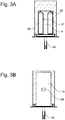
- FIGS. 3A and 3B both show a section through the sample chamber 4 without sample holder along the line AA or BB, which in FIG. 1 are shown.
- FIG. 3A are two recesses 36 for two sample vessels with lid and receptacle to recognize. Furthermore, the connection of the temperature sensor 16 can be seen, which is arranged in this figure behind the image plane. Characteristic features of the empty sample chamber 4 are used in the method according to the invention for determining the origin of the coordinates.
- Characteristic features of the empty sample chamber 4 are used in the method according to the invention for determining the origin of the coordinates.
- the horizontal positioning for example, one or both inner edges 37 of the recesses 36 can be used, which are recognizable as relatively sharply delineated vertical shadows in an image captured by the empty sample chamber 4.
- For the vertical Positioning is used at least one of the upper stops 38, to which the sample vessels with lid and collecting container strike when they are inserted. The stops 38 are reflected in the image data as sharp horizontal lines.
- the position of the shadow of at least one of the inner edges 37 is detected as a horizontal component of the coordinate origin and that of the stop 36 as a vertical component and the image recognition or the inventive method aligne
- FIG. 3B shows a section through the sample chamber along the line BB, which with respect to the means for digital image acquisition (5 in FIG. 1 ) is in front of the window 15.
- a rectangular color area 39 of a given color, here white can be recognized, which is detected in the method according to the invention for performing white and / or color matching and registered as a specific color.
- the colors of the further images are digitally or mathematically adapted to the predetermined value of the color surface, for example RGB 100 100 100.
- the window 15 is transparent and has been here in FIG. 3B shown opaque for simplicity.
- FIG. 4 shows a schematic, three-dimensional representation of a sample holder 7 for two samples.
- the substance to be analyzed can be filled into a sample vessel 8, which is placed on a transparent collecting container 10.
- the sample vessel 8 has an inlet and an outlet, through which outlet the sample emerges as a droplet when heated.
- a lid 9 is also arranged on the sample vessel 8.
- the collecting container 10, the sample vessel 8 and the lid 9 are stacked, but not firmly connected to each other here.
- the sample holder 7 comprises a handle 18, which is connected via a first web 19 with a curved clamp, which consists of two spring elements 20.
- the free ends of the spring elements 20 are connected to one another via a transverse web 21, which comprises two recesses 22 for a part of the lid 9.
- a further web 23 is arranged on the first web 19, which extends perpendicularly away from the handle 18 and which ends in a spade-like element 24.
- the spade-like element 24 has two vertical recesses 25 and two annular holders 26, in which the collecting container 10 are used can.
- the vertical recesses 25 define the measuring range detected by the means for digital image acquisition.
- the sample holder 7 inserted in the measuring device is oriented so that the sample containers 8 are directed away from the means for digital image acquisition.
- the collecting containers 10 are transparent as shown here, so that the temporal behavior of the sample, such as a drop formation due to the heating of the sample, can be detected with the means for digital image acquisition.
- a detection means 27 may be arranged in the center strut of the spade-shaped element 24.
- the detection means 27 is designed here as a hole and is used for automatic detection of the sample holder when inserted into the sample chamber by the means for digital image acquisition.
- the recognition means 27 can have different sizes, shapes and / or positions on the sample holder 7, so that a distinction can be made between different sample holders 7 in the recognition.
- the sample holder may also comprise a plurality of identical or different detection means.
- As a detection means in addition to the hole shown here, several holes, other distinctive markers and machine-readable codes, such as barcodes or smart codes, or electronically detectable markings, such as RFID tags are used.
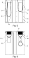
- FIGS. 5 and 6 show schematically recordings of the interior of the sample chamber during a determination of the softening or dripping point.
- a white or color balance is carried out in order to adapt and / or set the color spectrum of the means for digital image acquisition.
- an area with a defined color, preferably white arranged (s. FIG. 3B ). This area is detected prior to the introduction of the samples and the means for digital image capture adjusted such that the captured image of this area corresponds to a predetermined color, for example R 100 G 100 B 100, the RGB color scheme.
- the color and / or white balance allows the acquisition of comparable image-time data, which are comparable in particular due to the colors shown.
- white and / or color matching allows changes compensate for the light source used to illuminate the sample chamber, here an LED lamp.
- a coordinate origin or coordinate zero point is determined, so that the determination can be carried out with the best possible and high reproducibility.
- at least one predetermined point of the detected image is set as the coordinate origin, and the determination of the temporal change of the sample in relation to this coordinate origin is performed.
- a preferred fixed point for determining the origin of coordinates is, for example, the position of the sample chamber.
- the origin of coordinates should be determined from a characteristic feature in the image, which is easy to recognize and allows both horizontal and vertical position determination, see FIG. 3A ,
- a brightness adjustment can be carried out before or after the determination of the origin of the coordinates, wherein preferably the coordinate origin is determined first.
- the brightness adjustment is to ensure that the image time data is acquired at substantially the same brightness ratios. In this way, the reproducibility of measurements of similar samples at different times can be improved.
- the brightness adjustment can be carried out in one of the methods described. Preferably, the exposure times are adjusted.
- the color balance, the brightness adjustment as well as the determination of the coordinate origin is performed automatically after the start of the measuring device. This can be done in the order shown here or in any order.
- a corresponding program is stored in the control unit, more precisely the processor unit located therein.
- the measuring device is ready to measure and at least one sample can be prepared and preferably filled into a suitable sample vessel for the respective measurement.
- the sample vessel can then be inserted into a sample holder, as described in connection with FIG. 4 has been described. Frequently, two or more samples are measured simultaneously.
- the user Before inserting the sample holder into the measuring device, the user can determine the measuring and sample parameters and input them via the display and / or operating unit. These may include, for example, information on the substance, the temperature-time setpoints to be specified, the starting temperature and other information relevant to the user.
- a sample-specific brightness calibration can be carried out again, so that similar contrast ratios are created for the substance to be analyzed, ie the contrast between substance and background is substantially the same.
- the link between brightness and a specific substance can be stored for example in a database in the control unit. This can already be factory set for adjusting and / or calibration substances or determined by the user, which is particularly suitable for series measurements or for measurements in the field of quality assurance, if the same or very similar substances or samples are often measured.
- the measurement may be initiated by the user or automatically started by detecting a detection means on the sample holder.
- the measurement comprises the selection of the measuring method, ie the determination of the dropping point or softening point, the setting of the desired starting temperature and the heating up of the sample chamber to this temperature.
- the heating device heats the sample chamber and thus the sample in accordance with predetermined temperature-time setpoints.
- the temperature-time data and the image-time data are acquired and preferably stored at predetermined times or continuously.
- the first dropping event is determined from the time change of the sample and the associated temperature detected as a dropping point or the temperature is detected as a softening point at which the first drop reaches a predetermined length.
- one or more rheological properties of the sample can also be determined from their temporal change.
- the analysis of the image-time data can give the user information about the temperature-dependent rheological behavior of the substance to be analyzed.
- FIG. 5 one can see the scheme of a typical recording for the determination of the softening point.
- the recording shows the interior of the sample chamber, more precisely the area in which the collecting containers are arranged.
- two samples 28, 29 are arranged, which have expanded due to the heating and formed one drop each.
- a scale 30 is superimposed on the recording of the drop and an evaluation area 31 is indicated by a superimposed frame.
- the length of the drop is determined, which is also indicated to the user by displaying a horizontal bar 32, which always marks the bottom of the drop.
- the associated temperature is registered as a softening point.
- FIG. 6 also shows schematically a recording from the inside of the sample chamber at a drop point determination. Again, the area covered by the image processing means, which includes the receptacles, is shown. The recording represents the time at which the dripping point is reached. This is detected by digitally detecting the displayed evaluation window 35 and registering the tear-off of a droplet 34 from the substance 33. The associated temperature is then recorded as dropping point.
- a rheological property of the substance can also be determined from the determined temperature-time actual values and the image-time data, in particular the viscosity.
- the drip frequency can be determined and evaluated.
Description
Die Erfindung betrifft ein Verfahren zur Bestimmung des Erweichungs- oder Tropfpunkts einer Substanz und insbesondere ein automatisiertes Verfahren.The invention relates to a method for determining the softening or drip point of a substance, and more particularly to an automated method.
Die Bestimmung des Erweichungs- oder Tropfpunkts ist ein allgemein anerkanntes Verfahren zur Bestimmung von charakteristischen Eigenschaften eines Stoffes oder einer Substanz.
Der Tropfpunkt bezeichnet die Temperatur, bei der eine Substanz unter vorgegebenen und häufig genormten Prüfbedingungen zu fließen beginnt. Dabei wird die Substanz so lange kontrolliert erwärmt, bis diese vom festen in den flüssigen Aggregatzustand übergeht. Während der Messung wird die Temperatur erfasst, bei der sich ein erster Tropfen von der Substanz löst. Die Tropfpunktbestimmung kann gemäss einer der gängigen Normen, wie beispielsweise ASTM D3954, Ph. Eur. 2.2.17 (Pharmacopoea Europaea) oder AOCS Cc 18-18 (American Oil Chemists' Society), durchgeführt werden. Insbesondere bei Polymeren, Rohpolymer, Wachsen, Polyolefinen, Paraffinen, Schmierfetten, organischen Pulvern, Vaseline, Speisefetten, Speiseölen und verwandten Stoffen wird diese zur Charakterisierung sowie auch zur Qualitätskontrolle eingesetzt.The drop point is the temperature at which a substance begins to flow under predetermined and often standardized test conditions. The substance is heated until it changes from the solid to the liquid state. During the measurement, the temperature is detected at which a first drop of the substance dissolves. The dropping point determination can be carried out according to one of the common standards, such as ASTM D3954, Ph. Eur. 2.2.17 (Pharmacopoea Europaea) or AOCS Cc 18-18 (American Oil Chemists' Society). In particular, in the case of polymers, raw polymer, waxes, polyolefins, paraffins, lubricating greases, organic powders, vaseline, edible fats, edible oils and related substances, these are used for characterization and also for quality control.
Der Erweichungspunkt ist ein Messwert zur Klassifizierung von beispielsweise Bitumen und bituminösen Substanzen. Der Erweichungspunkt kann mittels eines als Ring-und-Kugel bezeichneten Verfahrens bestimmt werden, wie es beispielsweise in
Auch
Die zu analysierende Probe oder Substanz kann flüssig oder fest sein sowie einen Zwischenzustand umfassen. Beispielhaft kann die Substanz als flüssig, fest, wachsartig, bituminös, zähflüssig oder pulverförmig beschrieben werden.The sample or substance to be analyzed may be liquid or solid and include an intermediate state. By way of example, the substance can be described as liquid, solid, waxy, bituminous, viscous or pulverulent.
Bislang sind vor allem Messgeräte bekannt mit denen entweder der Erweichungspunkt oder der Tropfpunkt bestimmt werden kann. Die Bestimmungen erfolgen häufig in Messgeräten mit einer beheizbaren Probenkammer. Die zu analysierende Substanz wird in ein geeignetes Probengefäss gefüllt und dieses wird in die Probenkammer eingebracht, in welcher die Probe, insbesondere die Substanz im Probengefäss, anschliessend erwärmt wird.So far, especially measuring devices are known with which either the softening point or the dropping point can be determined. The determinations are often made in measuring instruments with a heatable sample chamber. The substance to be analyzed is filled into a suitable sample vessel and this is introduced into the sample chamber, in which the sample, in particular the substance in the sample vessel, is subsequently heated.
Das Erreichen des Erweichungspunktes wird ermittelt, wenn der erste Tropfen der Substanz eine vorgegebene Länge erreicht und zum Beispiel eine entsprechend angeordnete Lichtschranke durchbricht. Die Temperatur zu diesem Zeitpunkt wird als Erweichungspunkt registriert.The reaching of the softening point is determined when the first drop of the substance reaches a predetermined length and breaks through, for example, a correspondingly arranged light barrier. The temperature at this time is registered as a softening point.
Das Erreichen des Tropfpunktes wird ermittelt, wenn der ersten Tropfen von der Probe abfällt. Dieses Ereignis kann ebenfalls mittels einer Lichtschranke detektiert und die entsprechende Temperatur als Tropfpunkt erfasst werden.Reaching the dropping point is determined when the first drop falls off the sample. This event can also be detected by means of a light barrier and the corresponding temperature can be detected as a dropping point.
Die Messkammern bekannter Messgeräte sind meist geschlossen und können nicht direkt eingesehen werden. Dieses dient vor allem der Vermeidung von Kältebrücken an einem Fenster und somit der gleichmässigen Erwärmung der Probe. In weiteren bekannten Messgeräten werden Öl- oder Wasserbäder zum Erwärmen der Probe eingesetzt.The measuring chambers of known measuring devices are usually closed and can not be viewed directly. This is mainly used to avoid cold spots on a window and thus the uniform heating of the sample. In other known measuring devices oil or water baths are used to heat the sample.
- Bereitstellen eines Probengefässes mit einer Probe der Substanz, und Einbringen des Probengefässes in einer Probekammer;
- Einstellen der Probenkammer auf eine Strattemperatur;
- Aufheizen der Probenkammer mittels einer Heizvorrichtung gemäß vorgegebenen Temperatur-Zeit-Sollwerten;
- Messen von Temperatur-Zeit-Istwerten in der Probenkammer mit einem Temperaturfühler und erfassen von Daten aus dem Inneren der Probenkammer mit optischen Mitteln;
- Ermitteln der zeitlichen Veränderungen der Probe in Abhängigkeit der Temperatur anhand der erfassten Daten aus dem Inneren der Probenkammer und Temperatur-Zeit-Istwerte, welche die Bildung mindestens eines Tropfens sowie dessen Längenänderung und Abreißen aufgrund einer Erweichung der Probe durch die Wärmezufuhr der Heizvorrichtung umfasst; und
- Ermitteln des Tropfpunkts und des Erweichungspunkts der Probe anhand ihrer zeitlichen Veränderung in Abhängigkeit der Temperatur.
- Providing a sample vessel with a sample of the substance, and placing the sample vessel in a sample chamber;
- Setting the sample chamber to a line temperature;
- Heating the sample chamber by means of a heater according to predetermined temperature-time set values;
- Measuring temperature-time actual values in the sample chamber with a temperature sensor and acquiring data from inside the sample chamber by optical means;
- Determining the temporal changes of the sample as a function of the temperature based on the acquired data from the interior of the sample chamber and temperature-time actual values, which includes the formation of at least one drop and its change in length and tearing due to a softening of the sample by the heat supply of the heater; and
- Determine the drop point and the softening point of the sample based on their temporal change as a function of the temperature.
Daraus ergibt sich als Aufgabe die Bereitstellung eines Verfahrens sowie eines Messgeräts welches die Reproduzierbarkeit der Bestimmung des Tropf- und/oder Erweichungspunkts normkonformer Substanzen verbessert und welches zudem die Analyse von nicht-normkonformen Substanzen ermöglicht.It is therefore an object to provide a method and a measuring device which improves the reproducibility of the determination of the dripping and / or softening point of substances conforming to the standard and which also enables the analysis of substances which do not conform to standards.
Gelöst wird diese Aufgabe durch ein, im Anspruch 1 definiertes Verfahren zur Bestimmung des Erweichungs- oder Tropfpunkts einer Substanz mit einem Messgerät. Das Messgerät umfasst eine Probenkammer, einen Temperaturfühler, eine Heizvorrichtung, ein Mittel zur Bereitstellung von Temperatur-Zeit-Sollwerten, ein Mittel zur Bilderfassung, insbesondere einem Mittel zur digitalen Bilderfassung, und eine Steuereinheit mit einer Prozessoreinheit. Die Heizvorrichtung dient zum Erwärmen der Probenkammer anhand vorgegebener Temperaturen, wie den Temperatur-Zeit-Sollwerten. Mit dem Temperaturfühler kann die Temperatur im Inneren der Probenkammer erfasst werden und mit dem Mittel zur Bilderfassung kann das Innere der Probenkammer visuell erfasst werden.This object is achieved by a defined in
Das erfindungsgemässe Verfahren umfasst mehrere Schritte. Zunächst wird ein Probengefäss mit einer Probe der zu analysierenden Substanz bereitgestellt und in die Probenkammer eingebracht. Weiterhin werden Temperatur-Zeit-Sollwerte bereitgestellt. In der Probenkammer wird eine vorgegebene Starttemperatur eingestellt und anschliessend die Probenkammer gemäss den vorgegebenen Temperatur-Zeit-Sollwerten aufgeheizt. Während der Messung werden Temperatur-Zeit-Istwerte in der Probenkammer mit dem Temperaturfühler ermittelt und zudem Bild-Zeit-Daten aus dem Inneren der Probenkammer mit dem Mittel zur Bilderfassung erfasst. Anhand der erfassten Bild-Zeit-Daten und Temperatur-Zeit-Istwerte kann eine zeitliche Veränderung der Probe in Abhängigkeit der Temperatur ermittelt werden. Die zeitliche Veränderung der Probe umfasst eine Bildung mindestens eines Tropfens sowie dessen Längenänderung oder Abreissen aufgrund einer Erweichung der Probe durch die Wärmezufuhr der Heizvorrichtung (11), welche in den Bild-Zeit-Daten wiedergegeben wird. Anhand der zeitlichen Veränderung der Probe in Abhängigkeit der Temperatur kann deren Tropf- oder Erweichungspunkt ermittelt werden.The inventive method comprises several steps. First, a sample vessel with a sample of the substance to be analyzed is prepared and introduced into the sample chamber. Furthermore, temperature-time setpoints are provided. In the sample chamber, a predetermined starting temperature is set, and then the sample chamber is heated according to the predetermined temperature-time setpoints. During the measurement, temperature-time actual values are determined in the sample chamber with the temperature sensor and, in addition, image-time data from the interior of the sample chamber are recorded with the means for image acquisition. On the basis of the acquired image-time data and temperature-time actual values, a temporal change of the sample as a function of the temperature can be determined. The temporal change of the sample comprises formation of at least one drop and its change in length or tearing due to a softening of the sample by the heat input of the heating device (11), which is reproduced in the image-time data. On the basis of the temporal change of the sample as a function of the temperature of its drip or softening point can be determined.
Die Auswertung der erfassten Temperatur-Istwerte und Bild-Zeit-Daten ermöglicht die Erfassung des Tropf- oder Erweichungspunktes der Substanz. Zudem kann über den Verlauf der Temperatur-Zeit-Istwerte sowie der aus den Bild-Zeit-Daten ermittelten Änderung der Probe zudem auf weitere rheologische Werte, wie beispielsweise die Viskosität zurückgeschlossen werden.The evaluation of the recorded temperature actual values and image time data enables the detection of the dripping or softening point of the substance. In addition, it is also possible to deduce further rheological values, such as the viscosity, via the course of the temperature-time actual values and the change in the sample determined from the image-time data.
Die Bilderfassung ermöglicht zudem eine optische Kontrolle der Substanz während des Erwärmungsprozesses, wodurch die Reproduzierbarkeit der Messergebnisse erhöht werden kann, da Messfehler aufgrund von sich atypisch verhaltenden Proben leicht erkannt werden können. Solche Messfehler können beispielsweise auftreten, wenn bei der Bestimmung des Erweichungspunkts der entstehende Tropfen vor Erreichung der vorgegebenen Länge abreisst oder diese gar nicht erst erreicht, oder wenn bei der Tropfpunkt-Bestimmung Tropfen sehr unterschiedlicher Grösse, Form oder Farbe entstehen, was darauf hindeuten kann, dass die Probe sich ungleichmässig erwärmt, bzw. sich die Wärme ungleichmässig in der Probe ausbreitet. Die Reproduzierbarkeit der Messungen kann erhöht werden, indem das unterschiedliche Verhalten von mindestens zwei identischen Proben optisch und/oder visuell verfolgt werden kann und so Abweichungen zwischen den eigentlich identischen Proben erkannt werden können.The image acquisition also allows optical control of the substance during the heating process, whereby the reproducibility of the measurement results can be increased, since measurement errors due to atypical behaving samples can be easily recognized. Such measurement errors can occur, for example, if, during the determination of the softening point, the resulting drop breaks off before it reaches the predetermined length or does not even reach it, or if drops of very different size, shape or color are formed during the drop point determination, which may indicate that the sample heats up unevenly, or that the heat spreads unevenly in the sample. The reproducibility of the measurements can be increased by visually and / or visually observing the different behavior of at least two identical samples and thus detecting deviations between the actually identical samples.
Insbesondere für die Bestimmung des Erweichungspunkts besteht ein weiterer Vorteil darin, nicht-normkonformer Substanzen exakter messen zu können. Zu diesen zählen Substanzen deren Eigenspannung beim Erweichen abnimmt, so dass ein Tropfen von der Probe abreisst, bevor er die vorgegeben Länge erreicht hat, oder Substanzen deren Eigenspannung so hoch ist, dass sich kein Tropfen der vorgegebenen Länge ausbildet, sondern dieser vielmehr nur eine verkürzte Länge erreicht.In particular for the determination of the softening point, there is a further advantage in being able to measure substances which are not conforming to the standards more accurately. These include substances whose residual stress decreases on softening, so that a drop from the sample ruptures before it has reached the predetermined length, or substances whose residual stress is so high that no drop of the predetermined length is formed, but this only a shortened Length reached.
Das erfindungsgemässe Verfahren umfasst zudem einen Schritt eines Farb- und/oder Weissabgleichs welcher dazu dient das Farbspektrum des Mittels zur Bilderfassung bzw. des Bilderfassungsmittels anzupassen und/oder einzustellen. Dazu kann in der Probenkammer ein Bereich mit einer definierten Farbe, vorzugsweise weiss, angeordnet sein. Dieser Bereich wird vor dem Einbringen der Proben erfasst und das Mittel zur Bilderfassung derart eingestellt, dass das erfasste Bild dieses Bereiches einer vorgegebenen Farbe entspricht, beispielsweise R 100 G 100 B 100 des RGB Farbschemas oder einer anderen definierten Farbe. Der Farb- und/oder Weissabgleich ermöglicht die Erfassung von vergleichbaren Bild-Zeit-Daten, welche insbesondere aufgrund der gezeigten Farben vergleichbar sind. Auf diese Weise können beispielsweise bei Reihenmessungen Farbunterschiede zwischen den Proben erkannt werden, was für den Benutzer vorteilhaft sein kann, da unterschiedliche Farben auf eine unterschiedliche Zusammensetzung der zu analysierenden Substanz oder auch auf eine Zersetzung der Substanz hinweisen können.The inventive method also includes a step of color and / or white balance which serves to adjust and / or adjust the color spectrum of the means for image capture or the image acquisition means. For this purpose, an area with a defined color, preferably white, can be arranged in the sample chamber. This area is detected prior to the introduction of the samples, and the means for image acquisition is set such that the captured image of that area corresponds to a given color, for example R 100 G 100 B 100 of the RGB color scheme or another defined color. The color and / or white balance allows the acquisition of comparable image-time data, which are comparable in particular due to the colors shown. In this way, color differences between the samples can be detected, for example, in series measurements, which may be advantageous for the user, since different colors may indicate a different composition of the substance to be analyzed or even a decomposition of the substance.
Vorzugsweise umfasst das erfindungsgemässe Verfahren zudem einen Helligkeitsabgleich, wodurch sichergestellt werden soll, dass die Bild-Zeit-Daten bei im Wesentlichen gleichen Helligkeitsverhältnissen erfasst werden. Auf diese Weise kann die Reproduzierbarkeit von Messungen gleichartiger Proben zu verschiedenen Zeitpunkten verbessert werden. Der Helligkeitsabgleich kann auf unterschiedliche Weise erfolgen.Preferably, the inventive method also includes a brightness balance, which is to ensure that the image-time data are detected at substantially the same brightness ratios. In this way, the reproducibility of measurements of similar samples at different times can be improved. The brightness balance can be done in different ways.
Eine Möglichkeit besteht darin die Helligkeit einer regelbaren Lichtquelle anzupassen, welche die Probenkammer beleuchtet. Die Helligkeit wird derart angepasst, dass das Mittel zur Bilderfassung im Wesentlichen gleichartig ausgeleuchtete Bild-Zeit-Daten erfasst.One possibility is to adjust the brightness of a controllable light source which illuminates the sample chamber. The brightness is adjusted in such a way that the means for image acquisition acquires substantially uniformly illuminated image-time data.
Eine weitere Möglichkeit besteht darin die Belichtungszeiten bei der Aufnahme der Bild-Zeit-Daten anzupassen, indem beispielsweise ein Shutter, welcher ein Teil des Mittels zur Bilderfassung ist, länger oder kürzer geöffnet und so die Belichtungszeit angepasst wird. Vorzugsweise handelt es sich beim Shutter um einen elektronischen Shutter als Teil des Mittels zur digitalen Bilderfassung.Another possibility is to adjust the exposure times in the recording of the image-time data, for example by a shutter, which is part of the means for image acquisition, opened longer or shorter, and so the exposure time is adjusted. Preferably, the shutter is an electronic shutter as part of the means for digital image capture.
Weiterhin kann die Helligkeit in den Bild-Zeit-Daten rechnerisch angepasst werden. Auf diese Weise kann sichergestellt werden, dass sich alle Helligkeitswerte im Bild in einem definierten Bereich befinden, beispielsweise unter 200, unter der Annahme, dass 0 der kleinsten und 255 der grössten Helligkeit entspricht.Furthermore, the brightness in the image-time data can be adjusted mathematically. In this way, it can be ensured that all brightness values in the image are within a defined range, for example below 200, assuming that 0 corresponds to the lowest and 255 to the highest brightness.
Eine weitere Möglichkeit besteht darin, den rechnerischen Helligkeitsabgleich für eine oder mehrere bestimmte Substanzen zu definieren. Dieses ist insbesondere für Substanzen geeignet, welche als Justier- und/oder Kalibriersubstanz verwendet werden. Auf diese Weise können gleichartige Kontrastverhältnisse für diese Substanzen geschaffen werden, also dass der Kontrast zwischen einer vorgegebenen Substanz und dem Hintergrund an diese Substanz angepasst ist und beispielsweise bei Wiederholungsmessungen im Wesentlichen gleich ist. Die Verknüpfung zwischen Helligkeit und einer bestimmten Substanz kann beispielsweise in einer Datenbank in der Steuereinheit abgelegt werden.Another possibility is to define the calculated brightness balance for one or more specific substances. This is particularly suitable for substances which are used as adjustment and / or calibration substance. In this way, similar contrast ratios can be created for these substances, that is to say that the contrast between a given substance and the background is adapted to this substance and is essentially the same for example for repeat measurements. The link between brightness and a specific substance can be stored for example in a database in the control unit.
Im Laufe der Messung findet aufgrund der Erwärmung eine zeitliche Veränderung der Probe statt. Dieses kann insbesondere eine Tropfenbildung sein, welcher Tropfen sich in Abhängigkeit der zu analysierenden Substanz beim Erwärmen bildet und abreisst oder welcher sich durch die Erwärmung ausdehnt und insbesondere eine Längenänderung erfährt. Die Temperatur bei welcher der Tropfen abreisst bezeichnet den Tropfpunkt bzw. die Temperatur bei welcher der Tropfen eine vorgegebene Länge überschreitet den Erweichungspunkt. Für die meisten Substanzen kann entweder ein Tropfpunkt oder ein Erweichungspunkt bestimmt werden. Die zeitliche Veränderung der Probe wird anhand der Bild-Zeit-Daten ermittelt. Dazu kann über eine entsprechende Bildauswertung ermittelt werden, wann und bei welcher Temperatur, also zu welchem Zeitpunkt ein Tropf-Ereignis stattgefunden hat oder wann und bei welcher Temperatur der sich bildende Tropfen die vorgegebene Länge erreicht hat.In the course of the measurement, a temporal change of the sample takes place due to the heating. This can be, in particular, a drop formation, which drops forms and heats up as a function of the substance to be analyzed upon heating or which expands as a result of the heating and in particular undergoes a change in length. The temperature at which the drop breaks down denotes the dropping point or the temperature at which the drop of a predetermined length exceeds the softening point. For most substances either a dropping point or a softening point can be determined. The temporal change of the sample is determined on the basis of the image-time data. For this purpose, it can be determined via a corresponding image analysis, when and at which temperature, ie at which time a drip event has taken place or when and at which temperature the forming droplet has reached the predetermined length.
Damit diese Bestimmung mit einer möglichst guten und hohen Reproduzierbarkeit durchgeführt werden kann, kann das Verfahren weiterhin die Bestimmung eines Koordinaten-Ursprungs oder Koordinaten-Nullpunkts umfassen. Bei diesem Schritt wird mindestes ein vorgegebener Punkt des ermittelten Bildes als Koordinaten-Ursprung festgelegt und die Bestimmung der zeitlichen Veränderung der Probe in Relation zu diesem Koordinaten-Ursprung durchgeführt. Ein bevorzugter Fixpunkt zur Festlegung des Koordinaten-Ursprungs ist beispielsweise die Position der Probenkammer und insbesondere eines Ofens, welcher an die Probenkammer angrenzt und diese zumindest teilweise umschliesst. Diese oder eine andere im Messgerät fixierte Position kann in den Bild-Zeit-Daten der leeren Probenkammer vorzugsweise automatisch erkannt werden und als Koordinaten-Ursprung festgelegt werden.In order for this determination to be carried out with as good and high reproducibility as possible, the method may further comprise the determination of a coordinate origin or coordinate origin. In this step, at least one predetermined point of the detected image is set as the coordinate origin, and the determination of the temporal change of the sample in relation to this coordinate origin is performed. A preferred fixed point for determining the origin of coordinates is, for example, the position of the sample chamber and in particular of a furnace which adjoins the sample chamber and at least partially surrounds it. This or another position fixed in the measuring device can preferably be automatically recognized in the image-time data of the empty sample chamber and determined as the origin of the coordinates.
Die Bild-Zeit-Daten und/oder die Temperatur-Zeit-Daten können kontinuierlich, in vorbestimmten Zeitintervallen und/oder zu vorgegebenen Zeitpunkten erfasst werden.The image-time data and / or the temperature-time data can be acquired continuously, at predetermined time intervals and / or at predetermined times.
Anhand der zeitlichen Veränderung der Probe in Abhängigkeit der Temperatur kann beispielsweise der Tropfpunkt, der Erweichungspunkt und/oder die Viskosität als Stoffeigenschaft und/oder rheologische Eigenschaft ermittelt werden.On the basis of the temporal change of the sample as a function of the temperature, for example, the dropping point, the softening point and / or the viscosity can be determined as a substance property and / or rheological property.
Die Ist-Temperatur, ein Auswertebereich, der Messzeitpunkt und/oder eine Längenskala, welche sich insbesondere auf den festgelegten Koordinaten-Ursprung bezieht, können in den Bild-Zeit-Daten angezeigt und auf diese Weise mit den Bild-Zeit-Daten verknüpft werden. Dazu können beispielsweise eine Temperaturanzeige, der Auswertebereich und/oder eine Skala physisch so im Messgerät angeordnet sein, dass diese bei der Aufnahme der Bild-Zeit-Daten erfasst werden. Vorzugsweise können die Ist-Temperatur, der Auswertebereich, der Messzeitpunkt und/oder die Längenskala in die Bild-Zeit-Daten eingeblendet werden und auf diese Weise miteinander visuell verbunden werden, so dass die Daten insbesondere beim Abspielen zuvor gespeicherter Daten miteinander verknüpft angezeigt werden. Die gemeinsame Anzeige von Bild-Zeit-Daten, Ist-Temperatur, Auswertebereich, Messzeitpunkt und/oder Längenskala ist sowohl benutzerfreundlich, als auch für die Nachvollziehbarkeit und Nachverfolgbarkeit der Messungen sehr vorteilhaft. Der Messzeitpunkt kann beispielsweise über eine dem Messgerät zugeordnete Uhr erfasst und in die Bild-Zeit-Daten eingeblendet werden. Weiterhin kann der Messzeitpunkt über die Sampling-Rate, also vorgegebene, zeitlich beabstandete Mess-Zeitpunkte, ermittelt werden.The actual temperature, an evaluation range, the measurement time point and / or a length scale, which relates in particular to the specified coordinate origin, can be displayed in the image time data and in this way linked to the image time data. For this purpose, for example, a temperature display, the evaluation area and / or a scale can be physically arranged in the measuring device in such a way that they are detected when taking the image-time data. Preferably, the actual temperature, the evaluation range, the measurement time point and / or the length scale can be superimposed into the image time data and thus visually connected to one another, so that the data are displayed linked together, in particular when playing previously stored data. The common display of image time data, actual temperature, evaluation range, measurement time point and / or length scale is both user-friendly and very advantageous for the traceability and traceability of the measurements. The measurement time point can be detected, for example, via a clock assigned to the measuring device and displayed in the image time data. Furthermore, the measurement time point can be determined via the sampling rate, that is to say predetermined, time-spaced measurement times.
Das Messgerät kann ferner eine Kühlvorrichtung umfassen oder mit einer Kühlvorrichtung zusammenwirken, so dass die Probe in der Probenkammer auch gekühlt werden kann. Diese Ausgestaltung ist vorteilhaft, wenn die Erstarrungstemperatur der zu analysierenden Substanz unterhalb der Raumtemperatur liegt und vor der Bestimmung des Tropf- oder Erweichungspunkts abgekühlt werden muss. Vorzugsweise werden derartige Substanzen in vorgekühlte Probengefässe gefüllt und bis zum Beginn der Messung oder zumindest bis zum Einsetzen in die Probenkammer auf Temperaturen unterhalb ihrer Erstarrungstemperatur gekühlt. Die Kühlvorrichtung kann als separates Bauteil ausgebildet sein oder eine gemeinsame Einheit mit der Heizvorrichtung bilden.The meter may further include a cooling device or cooperate with a cooling device so that the sample in the sample chamber may also be cooled. This embodiment is advantageous if the solidification temperature of the substance to be analyzed is below the room temperature and must be cooled before the determination of the dropping or softening point. Such substances are preferably filled into precooled sample vessels and cooled to temperatures below their solidification temperature until the beginning of the measurement or at least until they are inserted into the sample chamber. The cooling device may be formed as a separate component or form a common unit with the heater.
Als Probengefässe werden vorzugsweise kleine Metall-Tiegel mit einer standardisierten Form verwendet, wie sie beispielsweise in den bereits angeführten Normen beschrieben werden. Die Probengefässe für die Tropfpunkt- und die Erweichungspunkt-Bestimmung weisen einen Einlass und einen Auslass auf und unterscheiden sich vor allem im Durchmesser des Auslasses, durch welchen die Probe beim Erwärmen als Tropfen austritt.As sample vessels preferably small metal crucibles are used with a standardized shape, as described for example in the standards already mentioned. The sample vessels for the drop point and the softening point determination have an inlet and an outlet and differ mainly in the diameter of the outlet, through which the sample emerges when heated as drops.
Das Mittel zur Bilderfassung ist als Mittel zur digitalen Bilderfassung ausgestaltet und kann insbesondere eine CMOS-Kamera, eine CCD-Kamera (charge-couple-device), eine andere bekannte digitale Videokamera oder ein anderes geeignetes Halbleiterelement zur Bilderfassung sein.The means for image acquisition is designed as a means for digital image capture and may be in particular a CMOS camera, a CCD camera (charge-couple-device), another known digital video camera or other suitable semiconductor element for image acquisition.
Nach Einstellen eines gewünschten Messablaufs oder Messprogramms, insbesondere der Starttemperatur und der gewünschten Temperatur-Zeit-Sollwerte, kann detektiert werden, dass die Probe in die Probenkammer eingebracht wurde, und dadurch die Messung der Temperatur-Zeit-Daten und/oder die Erfassung der Bild-Zeit-Daten durch Einbringen der Probe in die Probenkammer automatisch gestartet werden. Vorteilhafterweise werden ein oder mehrere gefüllte Probengefässe in einem Probenhalter angeordnet, welcher ein Erkennungsmerkmal umfasst. Das Erkennungsmerkmal ist insbesondere so ausgestaltet, dass dieses über die Bild-Zeit-Daten und/oder die Steuereinheit erkannt wird und so die Messung auslöst oder startet.After setting a desired measurement procedure or measurement program, in particular the start temperature and the desired temperature-time setpoint values, it can be detected that the sample has been introduced into the sample chamber and thereby the measurement of the temperature-time data and / or the acquisition of the image Time data are automatically started by introducing the sample into the sample chamber. Advantageously, one or more filled sample vessels are placed in a sample holder which comprises a detection feature. The identification feature is in particular designed such that it is detected via the image-time data and / or the control unit and thus triggers or starts the measurement.
Die Auswertung der gemessenen Bild-Zeit-Daten und Temperatur-Zeit-Daten kann online geschehen, wobei die Daten auch nach Abschluss der Messung, insbesondere offline, ausgewertet werden können.The evaluation of the measured image-time data and temperature-time data can be done online, wherein the data even after completion of the measurement, in particular offline, can be evaluated.
Die Steuereinheit kann mindestens einen Lese-Schreib-Speicher umfassen, in welchem sowohl die vorgegeben Temperatur-Zeit-Sollwerte, als auch die ermittelten Temperatur-Zeit-Istwerte sowie die Bild-Zeit-Daten gespeichert werden können. Auf diese Weise können die Messergebnisse dokumentiert werden und zudem für eine oder mehrere weitere Auswertungen herangezogen werden.The control unit may comprise at least one read-write memory, in which both the predetermined temperature-time setpoints, as well as the determined temperature-time actual values and the image-time data can be stored. In this way, the measurement results can be documented and also be used for one or more further evaluations.
Vorzugsweise ist zudem in der Steuereinheit ein Programm zur Durchführung des Verfahrens hinterlegt.Preferably, a program for carrying out the method is also stored in the control unit.
Das erfindungsgemässe Verfahren kann gleichzeitig an mindestens zwei in der Probenkammer befindlichen Substanzen durchgeführt werden, wodurch die Messunsicherheit verringert werden kann. Dazu kann das Messgerät einen Probenhalter umfassen, welcher zwei oder mehr Proben aufnehmen kann. Der Probenhalter kann zusammen mit den Proben in das Messgerät eingesetzt werden.The inventive method can be carried out simultaneously on at least two substances located in the sample chamber, whereby the Measurement uncertainty can be reduced. For this purpose, the measuring device may comprise a sample holder which can hold two or more samples. The sample holder can be inserted into the meter along with the samples.
Ein Messgerät zu Durchführung des erfindungsgemässen Verfahrens wird im Anspruch 13 definiert und umfasst eine Probenkammer, einen Temperaturfühler, welcher die Temperatur in der Probenkammer erfasst, eine Heizvorrichtung, ein Mittel zur Bereitstellung von Temperatur-Zeit-Sollwerten, wobei die Heizvorrichtung die Probenkammer gemäss den vorgegebenen Temperatur-Zeit-Sollwerten aufheizt, ein Mittel zur Bilderfassung, welche das Innere der Probenkammer visuell erfasst und eine Steuereinheit mit einer Prozessoreinheit, wobei eine in der Probenkammer bereitgestellte Probe mit der Heizvorrichtung gemäss den vorgegebenen Temperatur-Zeit-Sollwerten aufgeheizt werden kann. Mit dem Temperaturfühler können Temperatur-Zeit-Istwerte und mit dem Mittel zur Bilderfassung Bild-Zeit-Daten erfasst und die zeitliche Veränderung der Probe in Abhängigkeit der Temperatur ermittelt werden. Die zeitliche Veränderung der Probe umfasst eine Bildung mindestens eines Tropfens sowie dessen Längenänderung oder Abreissen aufgrund einer Erweichung der Probe durch die Wärmezufuhr der Heizvorrichtung (11), welche in den Bild-Zeit-Daten wiedergegeben wird. Die zeitliche Veränderung der Probe ermöglicht die Bestimmung des Tropf- oder Erweichungspunkts der Probe.A measuring device for carrying out the method according to the invention is defined in
Zur Durchführung des Verfahrens an zwei oder mehr Proben kann das Messgerät zudem einen Probenhalter mit mindestens zwei Aufnahmen umfassen. Weiterhin kann der Probenhalter für jede Probe ein Haltemittel umfassen.To carry out the method on two or more samples, the measuring device may also include a sample holder with at least two receptacles. Furthermore, the sample holder may comprise a holding means for each sample.
Vorzugsweise weist der Probenhalter zudem ein Erkennungsmittel auf, welches eine automatische Erkennung der Art des Probenhalters, beispielsweise der Anzahl der einsetzbaren Proben und/oder ob es sich um einen Probenhalter für die Tropfpunkt- oder Erweichungspunktbestimmung handelt. Das Erkennungsmittel kann nach dem Einsetzen über das Mittel zur Bilderfassung erfasst werden und kann dazu verwendet werden, eine vorgegebene Messung automatisch zu starten.Preferably, the sample holder also has a recognition means, which is an automatic recognition of the type of sample holder, for example, the number of usable samples and / or whether it is a sample holder for the dropping point or softening point determination. The detection means may be detected after insertion via the image acquisition means and may be used to automatically start a predetermined measurement.
Das erfindungsgemässe Verfahren sowie ein zur Durchführung geeignetes Messgerät werden anhand der folgenden Figuren näher beschrieben, wobei gleiche Elemente mit denselben Bezugszeichen versehen sind. Es zeigen:
- Fig. 1
- Eine Seitenansicht eines Messgerät mit einer Probenkammer, wobei das Messgerät teilweise im Schnitt dargestellt ist;
- Fig. 2
- eine schematische Darstellung der Probenkammer;
- Fig. 3A
- einen Schnitt durch die Probenkammer ohne Probenhalter entlang der Line A-A in
Figur 1 - Fig. 3B
- einen Schnitt durch die Probenkammer ohne Probenhalter entlang der Line B-B in
Figur 1 - Fig. 4
- eine schematische, dreidimensionale Darstellung eines Probenhalters;
- Fig. 5
- eine schematische Darstellung einer Aufnahme vom Inneren der Probenkammer während einer Bestimmung des Erweichungspunkts;
- Fig. 6
- eine schematische Darstellung einer Aufnahme vom Inneren der Probenkammer während einer Bestimmung des Tropfpunkts.
- Fig. 1
- A side view of a measuring device with a sample chamber, wherein the measuring device is shown partially in section;
- Fig. 2
- a schematic representation of the sample chamber;
- Fig. 3A
- a section through the sample chamber without sample holder along the line AA in
FIG. 1 ; - Fig. 3B
- a section through the sample chamber without sample holder along the line BB in
FIG. 1 ; - Fig. 4
- a schematic, three-dimensional representation of a sample holder;
- Fig. 5
- a schematic representation of a recording from the interior of the sample chamber during a determination of the softening point;
- Fig. 6
- a schematic representation of a recording from the interior of the sample chamber during a determination of the dropping point.
An mindestens einer Seite der Probenkammer 4 ist eine Heizvorrichtung 11, vorzugsweise eine Flachheizung, angeordnet, mit welcher die Probenkammer 4 und somit eine Probe anhand vorgegebener Temperatur-Zeit-Sollwerte erwärmt werden kann. Zur Messung von Temperatur-Zeit-Istwerten ist in der Probenkammer 4 zudem ein Temperaturfühler 16 angeordnet.On at least one side of the
Die zum digitalen Bilderfassungsmittel 5 ausgerichtete Fläche der Probenkammer 4 weist ein Fenster 15 auf, durch welches das Mittel zur digitalen Bilderfassung 5 Bild-Zeit-Daten vom Inneren der Probenkammer 4 aufnehmen kann. Zwischen dem Mittel zur digitalen Bilderfassung 5 und dem Fenster 15 ist eine Isolation 12 der Probenkammer 4 angeordnet, in welcher ein Kanal oder eine Aussparung 13 ausgebildet ist. Das Mittel zur digitalen Bilderfassung 5 wird gegen den Kanal 13 von einem weiteren Fenster 14 geschützt.The surface of the
In
Der Probenhalter 7 umfasst einen Griff 18, welcher über einen ersten Steg 19 mit einer gebogenen Klammer, welche aus zwei Federelementen 20 besteht, verbunden ist. Die freien Enden der Federelemente 20 sind über einen Quersteg 21 miteinander verbunden, welcher zwei Aussparungen 22 für einen Teil des Deckels 9 umfasst. Weiterhin ist am ersten Steg 19 ein weiterer Steg 23 angeordnet, welcher sich vom Griff 18 senkrecht weg erstreckt und welcher in einem spatenartigen Element 24 endet. Das spatenartige Element 24 hat zwei senkrechte Aussparungen 25 und zwei ringförmige Halterungen 26, in welche die Auffangbehälter 10 eingesetzt werden können. Die senkrechten Aussparungen 25 definieren den vom Mittel zur digitalen Bilderfassung erfassten Messbereich. Der im Messgerät eingesetzte Probenhalter 7 ist so orientiert, dass die Probengefässe 8 vom Mittel zur digitalen Bilderfassung weg gerichtete sind. Die Auffangbehälter 10 sind wie hier gezeigt transparent, so dass das zeitliche Verhalten der Probe, wie eine Tropfenbildung aufgrund der Erwärmung der Probe, mit dem Mittel zur digitalen Bilderfassung erfasst werden kann.The
Ein Erkennungsmittel 27 kann in der Mittelstrebe des spatenförmigen Elements 24 angeordnet sein. Das Erkennungsmittel 27 ist hier als Loch ausgestaltet und dient der automatischen Erkennung des Probenhalters beim Einsetzen in die Probenkammer durch das Mittel zur digitalen Bilderfassung. Das Erkennungsmittel 27 kann verschiedene Grössen, Formen und/oder Positionen auf dem Probenhalter 7 haben, so dass bei der Erkennung zwischen verschiedenen Probenhaltern 7 unterschieden werden kann. Selbstverständlich kann der Probenhalter auch mehrere gleichartige oder unterschiedliche Erkennungsmittel umfassen. Als Erkennungsmittel können neben dem hier gezeigten Loch auch mehrere Löcher, andere markante Kennzeichen sowie maschinenlesbare Codes, wie Barcodes oder Smartcodes, oder elektronisch erfassbare Kennzeichen, wie beispielsweise RFID-Tags eingesetzt werden.A detection means 27 may be arranged in the center strut of the spade-shaped
Zur Bestimmung des Tropfpunktes oder des Erweichungspunktes, wird in einem Ausführungsbeispiel nach dem Einschalten des Messgeräts ein Weiss- oder Farbabgleich durchgeführt, um das Farbspektrum des Mittels zur digitalen Bilderfassung anzupassen und/oder einzustellen. Dazu ist in der Probenkammer ein Bereich mit einer definierten Farbe, vorzugsweise weiss, angeordnet (s.
Anschliessend wird ein Koordinaten-Ursprung oder Koordinaten-Nullpunkt ermittelt, damit die Bestimmung mit einer möglichst guten und hohen Reproduzierbarkeit durchgeführt werden kann. Bei diesem Schritt wird mindestes ein vorgegebener Punkt des ermittelten Bildes als Koordinaten-Ursprung festgelegt und die Bestimmung der zeitlichen Veränderung der Probe in Relation zu diesem Koordinaten-Ursprung durchgeführt. Ein bevorzugter Fixpunkt zur Festlegung des Koordinaten-Ursprung ist beispielsweise die Position der Probenkammer. Der Koordinaten-Ursprung sollte anhand eines charakteristischen Merkmals im Bild ermittelt werden, welches leicht zu erkennen ist und sowohl eine horizontale als auch eine vertikale Positionsermittlung erlaubt, siehe
Ein Helligkeitsabgleich kann vor oder nach der Ermittlung des Koordinaten-Ursprungs durchgeführt werden, wobei vorzugsweise zuerst der Koordinaten-Ursprung ermittelt wird. Der Helligkeitsabgleich dient dazu sicherzustellen, dass die Bild-Zeit-Daten bei im Wesentlichen gleichen Helligkeitsverhältnissen erfasst werden. Auf diese Weise kann die Reproduzierbarkeit von Messungen gleichartiger Proben zu verschiedenen Zeitpunkten verbessert werden. Der Helligkeitsabgleich kann auf eine der beschriebenen Methoden durchgeführt werden. Vorzugsweise werden die Belichtungszeiten angepasst.A brightness adjustment can be carried out before or after the determination of the origin of the coordinates, wherein preferably the coordinate origin is determined first. The brightness adjustment is to ensure that the image time data is acquired at substantially the same brightness ratios. In this way, the reproducibility of measurements of similar samples at different times can be improved. The brightness adjustment can be carried out in one of the methods described. Preferably, the exposure times are adjusted.
Vorzugweise wird sowohl der Farbabgleich, der Helligkeitsabgleich als auch die Bestimmung des Koordinaten-Ursprungs automatisch nach dem Aufstarten des Messgeräts durchgeführt. Dieses kann in der hier dargestellten oder in einer beliebigen Reihenfolge geschehen. Dazu ist in der Steuereinheit, genauer der darin befindlichen Prozessoreinheit, ein entsprechendes Programm hinterlegt.Preferably, the color balance, the brightness adjustment as well as the determination of the coordinate origin is performed automatically after the start of the measuring device. This can be done in the order shown here or in any order. For this purpose, a corresponding program is stored in the control unit, more precisely the processor unit located therein.
Nun ist das Messgerät messbereit und es kann mindestens eine Probe vorbereitet und vorzugsweise in ein für die jeweilige Messung geeignetes Probengefäss eingefüllt werden. Das Probengefäss kann anschliessend in einen Probenhalter eingesetzt werden, wie er im Zusammenhang mit
Vor dem Einsetzen des Probenhalters in das Messgerät, können vom Benutzer die Mess- und Probenparameter bestimmt und über die Anzeige- und/oder Bedieneinheit eingegeben werden. Diese können beispielsweise Informationen zur Substanz, die vorzugebenden Temperatur-Zeit-Sollwerte, die Starttemperatur und weitere für den Benutzer relevante Informationen umfassen.Before inserting the sample holder into the measuring device, the user can determine the measuring and sample parameters and input them via the display and / or operating unit. These may include, for example, information on the substance, the temperature-time setpoints to be specified, the starting temperature and other information relevant to the user.
Nachdem der Probenhalter mit der mindestens einen Probe in das Messgerät eingesetzt wurde, kann nochmals ein probenspezifischer Helligkeitsabgleich durchgeführt werden, so dass gleichartige Kontrastverhältnisse für die zu analysierende Substanz geschaffen werden, also dass der Kontrast zwischen Substanz und Hintergrund im Wesentlichen gleich ist. Die Verknüpfung zwischen Helligkeit und einer bestimmten Substanz kann beispielsweise in einer Datenbank in der Steuereinheit abgelegt werden. Dieses kann für Justier- und/oder Kalibriersubstanzen bereits werksseitig vorgegeben werden oder durch den Benutzer festgelegt werden, was sich insbesondere bei Reihenmessungen oder für Messungen im Bereich der Qualitätssicherung eignet, wenn häufig gleiche oder sehr ähnliche Substanzen bzw. Proben vermessen werden.Once the sample holder with the at least one sample has been inserted into the measuring device, a sample-specific brightness calibration can be carried out again, so that similar contrast ratios are created for the substance to be analyzed, ie the contrast between substance and background is substantially the same. The link between brightness and a specific substance can be stored for example in a database in the control unit. This can already be factory set for adjusting and / or calibration substances or determined by the user, which is particularly suitable for series measurements or for measurements in the field of quality assurance, if the same or very similar substances or samples are often measured.
Die Messung kann durch den Benutzer ausgelöst werden oder automatisch durch Erkennung eines Erkennungsmittels am Probenhalter gestartet werden. Die Messung umfasst die Auswahl der Messmethode, also der Tropfpunkt- oder Erweichungspunktbestimmung, das Einstellen der gewünschten Starttemperatur und Aufheizen der Probenkammer auf diese Temperatur. Anschliessend heizt die Heizvorrichtung die Probenkammer und damit die Probe gemäss vorgegebenen Temperatur-Zeit-Sollwerten auf. Gleichzeitig werden zu vorbestimmten Zeitpunkten oder kontinuierlich die Temperatur-Zeit-Daten sowie die Bild-Zeit-Daten erfasst und vorzugsweise abgespeichert.The measurement may be initiated by the user or automatically started by detecting a detection means on the sample holder. The measurement comprises the selection of the measuring method, ie the determination of the dropping point or softening point, the setting of the desired starting temperature and the heating up of the sample chamber to this temperature. Subsequently, the heating device heats the sample chamber and thus the sample in accordance with predetermined temperature-time setpoints. At the same time, the temperature-time data and the image-time data are acquired and preferably stored at predetermined times or continuously.
Aus diesen Daten kann nun die zeitliche Veränderung der Probe ermittelt werden, dieses geschieht nahezu in Echtzeit und/oder kann nachträglich anhand der aufgenommenen und abgespeicherten Daten ermittelt werden.From this data, the time change of the sample can now be determined, this happens almost in real time and / or can be subsequently determined based on the recorded and stored data.
Aufgrund der eingestellten Parameter und der ausgewählten Messmethode wird aus der zeitlichen Veränderung der Probe das erste Tropfevent ermittelt und die zugehörige Temperatur als Tropfpunkt erfasst oder es wird die Temperatur als Erweichungspunkt erfasst, an welcher der erste Tropfen eine vorgegebene Länge erreicht.Based on the set parameters and the selected measuring method, the first dropping event is determined from the time change of the sample and the associated temperature detected as a dropping point or the temperature is detected as a softening point at which the first drop reaches a predetermined length.
In einem weiteren Schritt können zudem eine oder mehrere rheologische Eigenschaften der Probe aus deren zeitlicher Veränderung ermittelt werden. Bereits die Analyse der Bild-Zeit-Daten kann dem Benutzer Aufschluss über das temperaturabhängige rheologische Verhalten der zu analysierenden Substanz geben.In a further step, one or more rheological properties of the sample can also be determined from their temporal change. Already the analysis of the image-time data can give the user information about the temperature-dependent rheological behavior of the substance to be analyzed.
In
Zusätzlich kann aus den ermittelten Temperatur-Zeit-Istwerten und den Bild-Zeit-Daten auch eine rheologische Eigenschaft der Substanz ermittelt werden, insbesondere die Viskosität. Dazu kann beispielsweise die Tropffrequenz bestimmt und ausgewertet werden.
Claims (14)
- Method of determining the softening point or the dropping point of a substance with a measuring instrument that comprises a sample chamber (4), a temperature sensor (16), a heater device (11), a means for providing temperature/time target values, an image-recording means (5) and a controller unit (17) with a processor unit; wherein the heater device (11) heats the sample chamber (4), the temperature sensor (16) measures the temperature in the sample chamber (4), and the image-recording means (5) captures a visual image of the interior of the sample chamber (4); said method comprising the steps of:a. providing a sample receptacle (8) with a sample of the substance that is to be analyzed and setting the sample receptacle (8) into the sample chamber (4);b. setting the sample chamber (4) to a given starting temperature;c. providing temperature/time target values and heating the sample chamber (4) with the heater device (11) in accordance with the given temperature/time target values;d. measuring actual temperature/time values in the sample chamber (4) with the temperature sensor (16) and capturing image/time date from the interior of the sample chamber (4) with the image-recording means (5);e. determining the change of the sample over time as a function of the temperature based on the recorded image/time data and actual temperature/time data, wherein said change of the sample comprises the formation of at least one drop as well as the change in length or breaking-away of the drop due to a softening of the sample as a result of the heat introduced by the heater device (11); andf. determining the dropping point or the softening point of the sample based on the change over time of the sample as a function of the temperature;and wherein the method further comprises a color-balance adjustment and/or a white-balance adjustment, wherein the color spectrum rendered by the image-recording means (5) is adjusted by means of a color reference area (39) of a defined color which is arranged in the sample chamber (4).
- Method according to claim 1, characterized in that the image/time data of the substance are optically monitored during the heating process in order to detect measurement errors based on atypical behaviors of samples.
- Method according to claim 1 or 2, characterized in that the method comprises a brightness adjustment for the recording of the image/time data.
- Method according to claim 3, characterized in that the brightness adjustment is made by adjusting the brightness of an adjustable light source (40) or by adjusting an exposure time of the image-recording means (5), or through a mathematically calculated adjustment of the recorded digital image/time data.
- Method according to one of the claims 1 to 4, characterized in that the brightness adjustment additionally comprises a substance-specific contrast adjustment between a given value for the substance and the actual value.
- Method according to one of the claims 1 to 5, characterized in that the method comprises the determination of an origin of a coordinate system within the sample chamber (4).
- Method according to one of the claims 1 to 6, characterized in that the image/time data comprise a temperature indication, an area of evaluation (35) and/or a length measurement scale (30), so that the recorded image/time data also include information regarding the actual temperature in the sample chamber, the change in length, and/or the drop-formation behavior of the substance.
- Method according to one of the claims 1 to 7, characterized in that the sample chamber (4) is cooled and/or heated, wherein the measuring instrument additionally comprises a cooling device.
- Method according to one of the claims 1 to 8, characterized in that the image/time data and/or the temperature/time data are recorded in predetermined time intervals or continuously.
- Method according to one of the claims 1 to 9, characterized in that the steps of measuring the temperature/time data and recording the image/time data are started automatically by setting the sample into the sample chamber (4).
- Method according to one of the claims 1 to 10, characterized in that a program is stored in the processor unit of the controller unit (17), said program being operable to automatically detect from the image/time data when at least a given length of the sample is exceeded or when a drop-formation event has occurred, and to indicate the associated actual temperature to the user.
- Method according to one of the claims 1 to 11, characterized in that the recorded image/time data and the temperature/time data are stored in a read/write memory of the processor unit.
- Measuring instrument, operable to perform the method according to one of the claims 1 to 12, comprising a sample chamber (4), a means for providing temperature/time target values, a heater device (11) to heat the sample chamber (4) in accordance with the predetermined temperature/time target values, a temperature sensor (16) which measures the actual temperature/time values in the sample chamber (4), an image-recording means (5) which captures a visual image of the interior of the sample chamber (4) and records image/time data, and a controller unit (17) with a processor unit in which a program is stored for the execution of the method according to one of the claims 1 to 12; wherein based on the actual temperature/time data and recorded image/time data a change over time is determined which occurs in a sample that is arranged in the sample chamber (4); wherein said change over time comprises the formation of at least one drop as well as the change in length or breaking away of the drop due to the heat introduced by the heater device (11) which is recorded in the image/time data; and wherein based on the change over time of the sample, the dropping- or softening point of the sample is determined.
- Measuring instrument according to claim 13, characterized in that the measuring instrument further comprises a sample holder (7) with at least two seats (22) to hold samples, at least two holder means (26) for the samples and at least one means of identification (27).
Priority Applications (3)
| Application Number | Priority Date | Filing Date | Title |
|---|---|---|---|
| EP11179996.1A EP2565633B1 (en) | 2011-09-05 | 2011-09-05 | Method for determining softening or dropping point |
| US13/596,856 US9222903B2 (en) | 2011-09-05 | 2012-08-28 | Method of determining the softening- or dropping point |
| CN201210325752.6A CN102980908B (en) | 2011-09-05 | 2012-09-05 | The method for determining softening point or dropping point |
Applications Claiming Priority (1)
| Application Number | Priority Date | Filing Date | Title |
|---|---|---|---|
| EP11179996.1A EP2565633B1 (en) | 2011-09-05 | 2011-09-05 | Method for determining softening or dropping point |
Publications (2)
| Publication Number | Publication Date |
|---|---|
| EP2565633A1 EP2565633A1 (en) | 2013-03-06 |
| EP2565633B1 true EP2565633B1 (en) | 2018-06-13 |
Family
ID=44785325
Family Applications (1)
| Application Number | Title | Priority Date | Filing Date |
|---|---|---|---|
| EP11179996.1A Active EP2565633B1 (en) | 2011-09-05 | 2011-09-05 | Method for determining softening or dropping point |
Country Status (3)
| Country | Link |
|---|---|
| US (1) | US9222903B2 (en) |
| EP (1) | EP2565633B1 (en) |
| CN (1) | CN102980908B (en) |
Families Citing this family (8)
| Publication number | Priority date | Publication date | Assignee | Title |
|---|---|---|---|---|
| WO2014185809A1 (en) * | 2013-05-13 | 2014-11-20 | Bryzgalov Andrei Andreevich | Device for measuring the melting point of solid fats |
| CN105548241B (en) * | 2015-12-23 | 2018-11-06 | 交通运输部公路科学研究所 | The calibration method and device of asphalt softening point instrument |
| DE102016005070A1 (en) * | 2016-04-27 | 2017-11-02 | Fraunhofer-Gesellschaft zur Förderung der angewandten Forschung e.V. | Apparatus and method for monitoring the temperature of a cryopreserved biological sample |
| DE102016005133A1 (en) | 2016-04-27 | 2017-11-02 | Fraunhofer-Gesellschaft zur Förderung der angewandten Forschung e.V. | Method and device for monitoring the temperature of a cryopreserved biological sample |
| DE102016005075A1 (en) | 2016-04-27 | 2017-11-02 | Fraunhofer-Gesellschaft zur Förderung der angewandten Forschung e.V. | Method and device for monitoring the temperature of a cryopreserved biological sample |
| DE102016005078A1 (en) | 2016-04-27 | 2017-11-02 | Fraunhofer-Gesellschaft zur Förderung der angewandten Forschung e.V. | Apparatus and method for monitoring the temperature of a cryopreserved biological sample |
| CN112162002A (en) * | 2020-09-28 | 2021-01-01 | 昆明德源文化传播有限公司 | Enamel processing device, system and method for metal weaving |
| CN113655061A (en) * | 2021-09-23 | 2021-11-16 | 华志(福建)电子科技有限公司 | Method for identifying melting point of substance based on image and melting point instrument |
Family Cites Families (13)
| Publication number | Priority date | Publication date | Assignee | Title |
|---|---|---|---|---|
| US426160A (en) * | 1890-04-22 | Tack-driving machine | ||
| US3242277A (en) * | 1962-12-28 | 1966-03-22 | Atlantic Refining Co | Sensor switch for use with apparatus for determining the softening point of bituminous materials |
| US3587293A (en) * | 1968-08-15 | 1971-06-28 | United States Steel Corp | Apparatus for measuring the softening point of a solid |
| FR2497341A1 (en) | 1980-12-30 | 1982-07-02 | Socles Goudrons Derives | DEVICE FOR MEASURING THE DEFORMATION OF A MATERIAL UNDER THE EFFECT OF HEAT AND ITS APPLICATION TO THE DETERMINATION OF THE WETTING POWER OF BRAIS |
| JPS5862551A (en) * | 1981-10-12 | 1983-04-14 | Oputo Kigyo:Kk | Glass softening point measuring apparatus |
| DE3919920A1 (en) * | 1989-06-19 | 1991-01-03 | Leybold Ag | DEVICE FOR MEASURING THE TEMPERATURE OF A METAL OR METAL ALLOY MELT |
| US5758968A (en) * | 1996-07-15 | 1998-06-02 | Digimelt Inc. | Optically based method and apparatus for detecting a phase transition temperature of a material of interest |
| US6536944B1 (en) * | 1996-10-09 | 2003-03-25 | Symyx Technologies, Inc. | Parallel screen for rapid thermal characterization of materials |
| TW491945B (en) * | 2000-01-21 | 2002-06-21 | Wako Pure Chem Ind Ltd | Test device for a multi-item test and the method for producing the same as well as a measuring instrument for the test device |
| JP2005502861A (en) * | 2001-08-10 | 2005-01-27 | サイミックス テクノロジーズ, インコーポレイテッド | Apparatus and method for making and testing pre-formulations and system therefor |
| GB2406904A (en) * | 2003-10-09 | 2005-04-13 | Asahi Chemical Ind | Measuring the melting, softening or decomposition points by detecting a change in luminosity or reflectance of the sample |
| US7182509B2 (en) * | 2005-04-27 | 2007-02-27 | Advanced Instruments, Inc. | Nanoliter osmometer and method of operation |
| GB2464717B (en) * | 2008-10-24 | 2012-11-28 | Bibby Scient Ltd | Apparatus for measuring the melting point of a substance |
-
2011
- 2011-09-05 EP EP11179996.1A patent/EP2565633B1/en active Active
-
2012
- 2012-08-28 US US13/596,856 patent/US9222903B2/en active Active
- 2012-09-05 CN CN201210325752.6A patent/CN102980908B/en active Active
Non-Patent Citations (1)
| Title |
|---|
| ROEMER D ET AL: "An Apparatus for the Automatic Determination of Ubbelohde's Flow-Drop-Point of Waxes", FETTE Â SEIFEN Â ANSTRICHMITTEL,, vol. 69, no. 9, 1 January 1967 (1967-01-01), pages 646 - 651, XP001321285 * |
Also Published As
| Publication number | Publication date |
|---|---|
| EP2565633A1 (en) | 2013-03-06 |
| CN102980908A (en) | 2013-03-20 |
| CN102980908B (en) | 2018-10-09 |
| US20130058374A1 (en) | 2013-03-07 |
| US9222903B2 (en) | 2015-12-29 |
Similar Documents
| Publication | Publication Date | Title |
|---|---|---|
| EP2565633B1 (en) | Method for determining softening or dropping point | |
| DE10015516B4 (en) | Method for measuring the condition of oils or greases | |
| DE102014208768B4 (en) | Method and device for quality assurance | |
| DE102015113557B4 (en) | Sample device with reference mark | |
| EP3404403B1 (en) | Method and device for testing the quality of coated surfaces | |
| EP3298380B1 (en) | Method and examination system for examining and processing a microscopic sample | |
| EP2203776A1 (en) | Method for positioning biological samples in a microscopic arrangement | |
| DE102006019641A1 (en) | Improving accuracy of process parameter measurement in freeze drying using sensors within the drying and/or condenser chamber radio linked to an external control | |
| EP3102921A1 (en) | Method for functionally testing a measuring device | |
| EP2483658A1 (en) | Method and apparatus for carrying out hardness tests on tablets | |
| DE102013108722B4 (en) | Method and device for detecting defects of a flat surface | |
| DE1473242B2 (en) | Method and device for determining the melting point | |
| DE102020118801A1 (en) | MICROSCOPE AND PROCEDURE FOR DISTANCE DETERMINATION OF A SAMPLE REFERENCE PLANE | |
| EP3385698B1 (en) | Method for the analysis of surface measurements | |
| DE102014104704B4 (en) | Method and device for the computer-assisted evaluation of hardness tests of a test specimen | |
| DE102019131693A1 (en) | MEASURING DEVICE FOR EXAMINATION OF A SAMPLE AND METHOD OF DETERMINING AN ALTITUDE MAP OF A SAMPLE | |
| DE102018108771A1 (en) | Apparatus and method for optimized sheet metal testing | |
| DE2701276A1 (en) | METHOD AND DEVICE FOR MEASURING AND RECORDING THE FLOW PROPERTIES OF A LIQUID | |
| DE10125798B4 (en) | An imaging system for positioning a probe tip on a contact area of a microchip and a method of imaging | |
| DE3414866A1 (en) | Method and device for measuring the osmolarity of liquid samples | |
| DE102011002057A1 (en) | Method and device for testing a thermocouple | |
| DE19724252C2 (en) | Measuring head for use in an arrangement for determining the time of a color change of an indicator in a test tube for measuring the thermal stability of a solid and heatable sample located in the test tube, in particular PVC | |
| DE2701263A1 (en) | DEVICE FOR RECORDING THE FLOW PROPERTIES OF A LIQUID | |
| DE102005049220B4 (en) | Method and apparatus for testing the decay time of solid samples in liquids | |
| DE1903145A1 (en) | Method and device for determining the crystallization point of a liquid |
Legal Events
| Date | Code | Title | Description |
|---|---|---|---|
| PUAI | Public reference made under article 153(3) epc to a published international application that has entered the european phase |
Free format text: ORIGINAL CODE: 0009012 |
|
| AK | Designated contracting states |
Kind code of ref document: A1 Designated state(s): AL AT BE BG CH CY CZ DE DK EE ES FI FR GB GR HR HU IE IS IT LI LT LU LV MC MK MT NL NO PL PT RO RS SE SI SK SM TR |
|
| AX | Request for extension of the european patent |
Extension state: BA ME |
|
| 17P | Request for examination filed |
Effective date: 20130826 |
|
| RBV | Designated contracting states (corrected) |
Designated state(s): AL AT BE BG CH CY CZ DE DK EE ES FI FR GB GR HR HU IE IS IT LI LT LU LV MC MK MT NL NO PL PT RO RS SE SI SK SM TR |
|
| RAP1 | Party data changed (applicant data changed or rights of an application transferred) |
Owner name: METTLER-TOLEDO GMBH |
|
| 17Q | First examination report despatched |
Effective date: 20170310 |
|
| GRAP | Despatch of communication of intention to grant a patent |
Free format text: ORIGINAL CODE: EPIDOSNIGR1 |
|
| INTG | Intention to grant announced |
Effective date: 20180104 |
|
| GRAS | Grant fee paid |
Free format text: ORIGINAL CODE: EPIDOSNIGR3 |
|
| GRAA | (expected) grant |
Free format text: ORIGINAL CODE: 0009210 |
|
| AK | Designated contracting states |
Kind code of ref document: B1 Designated state(s): AL AT BE BG CH CY CZ DE DK EE ES FI FR GB GR HR HU IE IS IT LI LT LU LV MC MK MT NL NO PL PT RO RS SE SI SK SM TR |
|
| REG | Reference to a national code |
Ref country code: GB Ref legal event code: FG4D Free format text: NOT ENGLISH |
|
| REG | Reference to a national code |
Ref country code: CH Ref legal event code: EP Ref country code: AT Ref legal event code: REF Ref document number: 1008999 Country of ref document: AT Kind code of ref document: T Effective date: 20180615 |
|
| REG | Reference to a national code |
Ref country code: FR Ref legal event code: PLFP Year of fee payment: 8 |
|
| REG | Reference to a national code |
Ref country code: IE Ref legal event code: FG4D Free format text: LANGUAGE OF EP DOCUMENT: GERMAN |
|
| REG | Reference to a national code |
Ref country code: DE Ref legal event code: R096 Ref document number: 502011014321 Country of ref document: DE |
|
| REG | Reference to a national code |
Ref country code: NL Ref legal event code: MP Effective date: 20180613 |
|
| REG | Reference to a national code |
Ref country code: LT Ref legal event code: MG4D |
|
| PG25 | Lapsed in a contracting state [announced via postgrant information from national office to epo] |
Ref country code: NO Free format text: LAPSE BECAUSE OF FAILURE TO SUBMIT A TRANSLATION OF THE DESCRIPTION OR TO PAY THE FEE WITHIN THE PRESCRIBED TIME-LIMIT Effective date: 20180913 Ref country code: CY Free format text: LAPSE BECAUSE OF FAILURE TO SUBMIT A TRANSLATION OF THE DESCRIPTION OR TO PAY THE FEE WITHIN THE PRESCRIBED TIME-LIMIT Effective date: 20180613 Ref country code: FI Free format text: LAPSE BECAUSE OF FAILURE TO SUBMIT A TRANSLATION OF THE DESCRIPTION OR TO PAY THE FEE WITHIN THE PRESCRIBED TIME-LIMIT Effective date: 20180613 Ref country code: BG Free format text: LAPSE BECAUSE OF FAILURE TO SUBMIT A TRANSLATION OF THE DESCRIPTION OR TO PAY THE FEE WITHIN THE PRESCRIBED TIME-LIMIT Effective date: 20180913 Ref country code: SE Free format text: LAPSE BECAUSE OF FAILURE TO SUBMIT A TRANSLATION OF THE DESCRIPTION OR TO PAY THE FEE WITHIN THE PRESCRIBED TIME-LIMIT Effective date: 20180613 Ref country code: LT Free format text: LAPSE BECAUSE OF FAILURE TO SUBMIT A TRANSLATION OF THE DESCRIPTION OR TO PAY THE FEE WITHIN THE PRESCRIBED TIME-LIMIT Effective date: 20180613 Ref country code: ES Free format text: LAPSE BECAUSE OF FAILURE TO SUBMIT A TRANSLATION OF THE DESCRIPTION OR TO PAY THE FEE WITHIN THE PRESCRIBED TIME-LIMIT Effective date: 20180613 |
|
| PG25 | Lapsed in a contracting state [announced via postgrant information from national office to epo] |
Ref country code: RS Free format text: LAPSE BECAUSE OF FAILURE TO SUBMIT A TRANSLATION OF THE DESCRIPTION OR TO PAY THE FEE WITHIN THE PRESCRIBED TIME-LIMIT Effective date: 20180613 Ref country code: LV Free format text: LAPSE BECAUSE OF FAILURE TO SUBMIT A TRANSLATION OF THE DESCRIPTION OR TO PAY THE FEE WITHIN THE PRESCRIBED TIME-LIMIT Effective date: 20180613 Ref country code: GR Free format text: LAPSE BECAUSE OF FAILURE TO SUBMIT A TRANSLATION OF THE DESCRIPTION OR TO PAY THE FEE WITHIN THE PRESCRIBED TIME-LIMIT Effective date: 20180914 Ref country code: HR Free format text: LAPSE BECAUSE OF FAILURE TO SUBMIT A TRANSLATION OF THE DESCRIPTION OR TO PAY THE FEE WITHIN THE PRESCRIBED TIME-LIMIT Effective date: 20180613 |
|
| PG25 | Lapsed in a contracting state [announced via postgrant information from national office to epo] |
Ref country code: NL Free format text: LAPSE BECAUSE OF FAILURE TO SUBMIT A TRANSLATION OF THE DESCRIPTION OR TO PAY THE FEE WITHIN THE PRESCRIBED TIME-LIMIT Effective date: 20180613 |
|
| PG25 | Lapsed in a contracting state [announced via postgrant information from national office to epo] |
Ref country code: PL Free format text: LAPSE BECAUSE OF FAILURE TO SUBMIT A TRANSLATION OF THE DESCRIPTION OR TO PAY THE FEE WITHIN THE PRESCRIBED TIME-LIMIT Effective date: 20180613 Ref country code: EE Free format text: LAPSE BECAUSE OF FAILURE TO SUBMIT A TRANSLATION OF THE DESCRIPTION OR TO PAY THE FEE WITHIN THE PRESCRIBED TIME-LIMIT Effective date: 20180613 Ref country code: IS Free format text: LAPSE BECAUSE OF FAILURE TO SUBMIT A TRANSLATION OF THE DESCRIPTION OR TO PAY THE FEE WITHIN THE PRESCRIBED TIME-LIMIT Effective date: 20181013 Ref country code: RO Free format text: LAPSE BECAUSE OF FAILURE TO SUBMIT A TRANSLATION OF THE DESCRIPTION OR TO PAY THE FEE WITHIN THE PRESCRIBED TIME-LIMIT Effective date: 20180613 Ref country code: CZ Free format text: LAPSE BECAUSE OF FAILURE TO SUBMIT A TRANSLATION OF THE DESCRIPTION OR TO PAY THE FEE WITHIN THE PRESCRIBED TIME-LIMIT Effective date: 20180613 Ref country code: SK Free format text: LAPSE BECAUSE OF FAILURE TO SUBMIT A TRANSLATION OF THE DESCRIPTION OR TO PAY THE FEE WITHIN THE PRESCRIBED TIME-LIMIT Effective date: 20180613 |
|
| PG25 | Lapsed in a contracting state [announced via postgrant information from national office to epo] |
Ref country code: SM Free format text: LAPSE BECAUSE OF FAILURE TO SUBMIT A TRANSLATION OF THE DESCRIPTION OR TO PAY THE FEE WITHIN THE PRESCRIBED TIME-LIMIT Effective date: 20180613 Ref country code: IT Free format text: LAPSE BECAUSE OF FAILURE TO SUBMIT A TRANSLATION OF THE DESCRIPTION OR TO PAY THE FEE WITHIN THE PRESCRIBED TIME-LIMIT Effective date: 20180613 |
|
| REG | Reference to a national code |
Ref country code: DE Ref legal event code: R097 Ref document number: 502011014321 Country of ref document: DE |
|
| PLBE | No opposition filed within time limit |
Free format text: ORIGINAL CODE: 0009261 |
|
| STAA | Information on the status of an ep patent application or granted ep patent |
Free format text: STATUS: NO OPPOSITION FILED WITHIN TIME LIMIT |
|
| PG25 | Lapsed in a contracting state [announced via postgrant information from national office to epo] |
Ref country code: MC Free format text: LAPSE BECAUSE OF FAILURE TO SUBMIT A TRANSLATION OF THE DESCRIPTION OR TO PAY THE FEE WITHIN THE PRESCRIBED TIME-LIMIT Effective date: 20180613 |
|
| 26N | No opposition filed |
Effective date: 20190314 |
|
| PG25 | Lapsed in a contracting state [announced via postgrant information from national office to epo] |
Ref country code: SI Free format text: LAPSE BECAUSE OF FAILURE TO SUBMIT A TRANSLATION OF THE DESCRIPTION OR TO PAY THE FEE WITHIN THE PRESCRIBED TIME-LIMIT Effective date: 20180613 Ref country code: DK Free format text: LAPSE BECAUSE OF FAILURE TO SUBMIT A TRANSLATION OF THE DESCRIPTION OR TO PAY THE FEE WITHIN THE PRESCRIBED TIME-LIMIT Effective date: 20180613 |
|
| REG | Reference to a national code |
Ref country code: BE Ref legal event code: MM Effective date: 20180930 |
|
| REG | Reference to a national code |
Ref country code: IE Ref legal event code: MM4A |
|
| PG25 | Lapsed in a contracting state [announced via postgrant information from national office to epo] |
Ref country code: LU Free format text: LAPSE BECAUSE OF NON-PAYMENT OF DUE FEES Effective date: 20180905 |
|
| PG25 | Lapsed in a contracting state [announced via postgrant information from national office to epo] |
Ref country code: IE Free format text: LAPSE BECAUSE OF NON-PAYMENT OF DUE FEES Effective date: 20180905 |
|
| PG25 | Lapsed in a contracting state [announced via postgrant information from national office to epo] |
Ref country code: BE Free format text: LAPSE BECAUSE OF NON-PAYMENT OF DUE FEES Effective date: 20180930 |
|
| REG | Reference to a national code |
Ref country code: AT Ref legal event code: MM01 Ref document number: 1008999 Country of ref document: AT Kind code of ref document: T Effective date: 20180905 |
|
| PG25 | Lapsed in a contracting state [announced via postgrant information from national office to epo] |
Ref country code: AL Free format text: LAPSE BECAUSE OF FAILURE TO SUBMIT A TRANSLATION OF THE DESCRIPTION OR TO PAY THE FEE WITHIN THE PRESCRIBED TIME-LIMIT Effective date: 20180613 |
|
| PG25 | Lapsed in a contracting state [announced via postgrant information from national office to epo] |
Ref country code: AT Free format text: LAPSE BECAUSE OF NON-PAYMENT OF DUE FEES Effective date: 20180905 Ref country code: MT Free format text: LAPSE BECAUSE OF FAILURE TO SUBMIT A TRANSLATION OF THE DESCRIPTION OR TO PAY THE FEE WITHIN THE PRESCRIBED TIME-LIMIT Effective date: 20180613 |
|
| PG25 | Lapsed in a contracting state [announced via postgrant information from national office to epo] |
Ref country code: TR Free format text: LAPSE BECAUSE OF FAILURE TO SUBMIT A TRANSLATION OF THE DESCRIPTION OR TO PAY THE FEE WITHIN THE PRESCRIBED TIME-LIMIT Effective date: 20180613 |
|
| PG25 | Lapsed in a contracting state [announced via postgrant information from national office to epo] |
Ref country code: HU Free format text: LAPSE BECAUSE OF FAILURE TO SUBMIT A TRANSLATION OF THE DESCRIPTION OR TO PAY THE FEE WITHIN THE PRESCRIBED TIME-LIMIT; INVALID AB INITIO Effective date: 20110905 Ref country code: PT Free format text: LAPSE BECAUSE OF FAILURE TO SUBMIT A TRANSLATION OF THE DESCRIPTION OR TO PAY THE FEE WITHIN THE PRESCRIBED TIME-LIMIT Effective date: 20180613 |
|
| PG25 | Lapsed in a contracting state [announced via postgrant information from national office to epo] |
Ref country code: MK Free format text: LAPSE BECAUSE OF NON-PAYMENT OF DUE FEES Effective date: 20180613 |
|
| PGFP | Annual fee paid to national office [announced via postgrant information from national office to epo] |
Ref country code: GB Payment date: 20230926 Year of fee payment: 13 |
|
| PGFP | Annual fee paid to national office [announced via postgrant information from national office to epo] |
Ref country code: FR Payment date: 20230926 Year of fee payment: 13 Ref country code: DE Payment date: 20230928 Year of fee payment: 13 |
|
| PGFP | Annual fee paid to national office [announced via postgrant information from national office to epo] |
Ref country code: CH Payment date: 20231001 Year of fee payment: 13 |