EP2565579A1 - Reference setting tool for measuring shape of side face spline, shape measuring device using the same, and shape measuring method using the same - Google Patents
Reference setting tool for measuring shape of side face spline, shape measuring device using the same, and shape measuring method using the same Download PDFInfo
- Publication number
- EP2565579A1 EP2565579A1 EP12179454A EP12179454A EP2565579A1 EP 2565579 A1 EP2565579 A1 EP 2565579A1 EP 12179454 A EP12179454 A EP 12179454A EP 12179454 A EP12179454 A EP 12179454A EP 2565579 A1 EP2565579 A1 EP 2565579A1
- Authority
- EP
- European Patent Office
- Prior art keywords
- teeth
- shape
- setting tool
- measuring
- hub unit
- Prior art date
- Legal status (The legal status is an assumption and is not a legal conclusion. Google has not performed a legal analysis and makes no representation as to the accuracy of the status listed.)
- Granted
Links
- 238000000034 method Methods 0.000 title claims description 17
- 238000005259 measurement Methods 0.000 claims description 23
- 238000013461 design Methods 0.000 description 18
- 238000007689 inspection Methods 0.000 description 11
- 239000000523 sample Substances 0.000 description 6
- 230000003028 elevating effect Effects 0.000 description 3
- 238000005096 rolling process Methods 0.000 description 3
- 239000000725 suspension Substances 0.000 description 3
- 238000005242 forging Methods 0.000 description 1
- 238000004519 manufacturing process Methods 0.000 description 1
- 238000012986 modification Methods 0.000 description 1
- 230000004048 modification Effects 0.000 description 1
- 230000000717 retained effect Effects 0.000 description 1
- 238000005070 sampling Methods 0.000 description 1
- 238000013519 translation Methods 0.000 description 1
Images



Classifications
-
- G—PHYSICS
- G01—MEASURING; TESTING
- G01B—MEASURING LENGTH, THICKNESS OR SIMILAR LINEAR DIMENSIONS; MEASURING ANGLES; MEASURING AREAS; MEASURING IRREGULARITIES OF SURFACES OR CONTOURS
- G01B5/00—Measuring arrangements characterised by the use of mechanical techniques
- G01B5/14—Measuring arrangements characterised by the use of mechanical techniques for measuring distance or clearance between spaced objects or spaced apertures
- G01B5/16—Measuring arrangements characterised by the use of mechanical techniques for measuring distance or clearance between spaced objects or spaced apertures between a succession of regularly spaced objects or regularly spaced apertures
- G01B5/166—Measuring arrangements characterised by the use of mechanical techniques for measuring distance or clearance between spaced objects or spaced apertures between a succession of regularly spaced objects or regularly spaced apertures of gear teeth
-
- F—MECHANICAL ENGINEERING; LIGHTING; HEATING; WEAPONS; BLASTING
- F16—ENGINEERING ELEMENTS AND UNITS; GENERAL MEASURES FOR PRODUCING AND MAINTAINING EFFECTIVE FUNCTIONING OF MACHINES OR INSTALLATIONS; THERMAL INSULATION IN GENERAL
- F16D—COUPLINGS FOR TRANSMITTING ROTATION; CLUTCHES; BRAKES
- F16D1/00—Couplings for rigidly connecting two coaxial shafts or other movable machine elements
- F16D1/06—Couplings for rigidly connecting two coaxial shafts or other movable machine elements for attachment of a member on a shaft or on a shaft-end
- F16D1/076—Couplings for rigidly connecting two coaxial shafts or other movable machine elements for attachment of a member on a shaft or on a shaft-end by clamping together two faces perpendicular to the axis of rotation, e.g. with bolted flanges
-
- G—PHYSICS
- G01—MEASURING; TESTING
- G01B—MEASURING LENGTH, THICKNESS OR SIMILAR LINEAR DIMENSIONS; MEASURING ANGLES; MEASURING AREAS; MEASURING IRREGULARITIES OF SURFACES OR CONTOURS
- G01B21/00—Measuring arrangements or details thereof, where the measuring technique is not covered by the other groups of this subclass, unspecified or not relevant
- G01B21/02—Measuring arrangements or details thereof, where the measuring technique is not covered by the other groups of this subclass, unspecified or not relevant for measuring length, width, or thickness
- G01B21/04—Measuring arrangements or details thereof, where the measuring technique is not covered by the other groups of this subclass, unspecified or not relevant for measuring length, width, or thickness by measuring coordinates of points
- G01B21/042—Calibration or calibration artifacts
-
- G—PHYSICS
- G01—MEASURING; TESTING
- G01B—MEASURING LENGTH, THICKNESS OR SIMILAR LINEAR DIMENSIONS; MEASURING ANGLES; MEASURING AREAS; MEASURING IRREGULARITIES OF SURFACES OR CONTOURS
- G01B5/00—Measuring arrangements characterised by the use of mechanical techniques
- G01B5/003—Measuring of motor parts
-
- G—PHYSICS
- G01—MEASURING; TESTING
- G01B—MEASURING LENGTH, THICKNESS OR SIMILAR LINEAR DIMENSIONS; MEASURING ANGLES; MEASURING AREAS; MEASURING IRREGULARITIES OF SURFACES OR CONTOURS
- G01B5/00—Measuring arrangements characterised by the use of mechanical techniques
- G01B5/004—Measuring arrangements characterised by the use of mechanical techniques for measuring coordinates of points
- G01B5/008—Measuring arrangements characterised by the use of mechanical techniques for measuring coordinates of points using coordinate measuring machines
-
- F—MECHANICAL ENGINEERING; LIGHTING; HEATING; WEAPONS; BLASTING
- F16—ENGINEERING ELEMENTS AND UNITS; GENERAL MEASURES FOR PRODUCING AND MAINTAINING EFFECTIVE FUNCTIONING OF MACHINES OR INSTALLATIONS; THERMAL INSULATION IN GENERAL
- F16D—COUPLINGS FOR TRANSMITTING ROTATION; CLUTCHES; BRAKES
- F16D3/00—Yielding couplings, i.e. with means permitting movement between the connected parts during the drive
- F16D3/16—Universal joints in which flexibility is produced by means of pivots or sliding or rolling connecting parts
- F16D3/20—Universal joints in which flexibility is produced by means of pivots or sliding or rolling connecting parts one coupling part entering a sleeve of the other coupling part and connected thereto by sliding or rolling members
- F16D3/22—Universal joints in which flexibility is produced by means of pivots or sliding or rolling connecting parts one coupling part entering a sleeve of the other coupling part and connected thereto by sliding or rolling members the rolling members being balls, rollers, or the like, guided in grooves or sockets in both coupling parts
- F16D3/223—Universal joints in which flexibility is produced by means of pivots or sliding or rolling connecting parts one coupling part entering a sleeve of the other coupling part and connected thereto by sliding or rolling members the rolling members being balls, rollers, or the like, guided in grooves or sockets in both coupling parts the rolling members being guided in grooves in both coupling parts
- F16D2003/22326—Attachments to the outer joint member, i.e. attachments to the exterior of the outer joint member or to the shaft of the outer joint member
-
- Y—GENERAL TAGGING OF NEW TECHNOLOGICAL DEVELOPMENTS; GENERAL TAGGING OF CROSS-SECTIONAL TECHNOLOGIES SPANNING OVER SEVERAL SECTIONS OF THE IPC; TECHNICAL SUBJECTS COVERED BY FORMER USPC CROSS-REFERENCE ART COLLECTIONS [XRACs] AND DIGESTS
- Y10—TECHNICAL SUBJECTS COVERED BY FORMER USPC
- Y10S—TECHNICAL SUBJECTS COVERED BY FORMER USPC CROSS-REFERENCE ART COLLECTIONS [XRACs] AND DIGESTS
- Y10S33/00—Geometrical instruments
- Y10S33/14—Spline and gear
Definitions
- the invention relates to a reference setting tool used to measure the shape of driven teeth (spline teeth) of a side face spline formed on a vehicle hub unit, a shape measuring device using the reference setting tool, and a shape measuring method using the reference setting tool.
- a hub unit is used to support a wheel of an automobile such that the wheel is rotatable with respect to a suspension.
- a side face spline having driven teeth (spline teeth) to be meshed with drive teeth, formed on an outer ring of a constant velocity joint is formed on an axially inner end face (an end face on the inner side in the vehicle lateral direction) of a hub wheel to which a drive wheel is fitted (refer to, for example, Published Japanese Translation of PCT Application No. 2008-536737 ( JP 2008-536737 A ) and Japanese Patent Application Publication No. 2008-174178 ( JP 2008-174178 A )).
- torque of a drive shaft of an automobile is transmitted from the constant velocity joint to the hub wheel via the driven teeth.
- the driven teeth of the above-described side face spline need to satisfy predetermined accuracy requirements for various dimensions such as a tooth flank size, an arrangement pitch and a coaxiality with respect to the rotation center, in order to appropriately mesh the driven teeth with the drive teeth of the constant velocity joint. Therefore, after a hub unit is manufactured, an inspection process is carried out. In the inspection process, for example, a three-dimensional measuring device is used to measure various dimensions of the driven teeth, and whether predetermined accuracies are achieved is checked.
- the shape of the driven teeth of the side face spline is usually designed using a pitch surface when the driven teeth are in mesh with the drive teeth of the constant velocity joint, as a reference surface (e.g. an imaginary plane indicated by the long dashed double-short dashed line ⁇ in FIG. 2 ; hereinafter, also referred to as "design reference surface").
- a reference surface e.g. an imaginary plane indicated by the long dashed double-short dashed line ⁇ in FIG. 2 ; hereinafter, also referred to as "design reference surface”
- design reference surface is just an imaginary plane
- the design reference surface cannot be used to measure the shape of the driven teeth of an actual product in the inspection process. Therefore, in related art, various dimensions of spline teeth are measured using a worked surface, such as a flange surface and a wheel fitting surface of a hub wheel, as a temporary reference surface. However, this increases measurement errors, which makes it difficult to stably carry out accurate dimension measurement.
- An aspect of the invention relates to a reference setting tool for measuring the shape of a side face spline, which is used to measure the shape of driven teeth that are formed on an axial end face of a vehicle hub unit and that are meshed with drive teeth of a constant velocity joint.
- the reference setting tool includes: reference teeth that are formed so as to be aligned along a circular ring and so as to have the same shape as the drive teeth of the constant velocity joint; and a reference surface that has a predetermined correlation with the reference teeth, and that is used to set a reference position for measuring the shape of the driven teeth with the reference teeth in mesh with the driven teeth.
- FIG. 1 is a sectional view that shows a vehicle hub unit according to the embodiment of the invention.
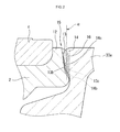
- FIG. 2 is an enlarged sectional view of a clinched portion of the vehicle hub unit.
- the vehicle hub unit 1 supports a wheel of an automobile such that the wheel is rotatable with respect to a suspension.
- the vehicle hub unit 1 includes a hub wheel 3, an inner ring member 4, an outer ring 5, and a plurality of rolling elements 6.
- the hub wheel 3 has a cylindrical hub spindle 2.
- the inner ring member 4 is fixed to an inner end portion, in the vehicle lateral direction (right end portion in FIG. 1 ), of the hub spindle 2 through clinching.
- the outer ring 5 is arranged radially outward of the hub spindle 2.
- the rolling elements 6 are rollably arranged between outer ring raceways 5a, 5b that are formed on the inner periphery of the outer ring 5 and inner ring raceways 2a, 4a that are formed on the outer periphery of the hub spindle 2 and the outer periphery of the inner ring member 4, respectively.
- the rolling elements 6 are retained by a cage 20 at predetermined intervals in the circumferential direction.
- seal members 21 are provided in an annular clearance formed between the outer ring 5 and the hub wheel 3. The seal members 21 close the annular clearance at respective axial ends.
- a flange 7 is formed at an outer end portion in the vehicle lateral direction (left end portion in FIG. 1 ), of the hub wheel 3.
- the flange 7 has holes 7a into which bolts (not shown) are fitted.
- bolts for example, a wheel of a tire and a brake disc are fitted to the flange 7 with the bolts.
- a fixing flange 8 is formed on the outer periphery of the outer ring 5. The fixing flange 8 is used to fit the hub unit 1 to a vehicle body member (not shown) supported by the suspension of the vehicle.
- the hub spindle 2 is a single-piece member that has a large-diameter portion 9 and a small-diameter portion 11.
- the large-diameter portion 9 is formed on the flange 7-side.
- the small-diameter portion 11 is smaller in diameter than the large-diameter portion 9, and is contiguous with the large-diameter portion 9 via a step 10.
- the inner ring raceway 2a is formed on the outer periphery of the large-diameter portion 9.
- the inner ring raceway 2a corresponds to the outer ring raceway 5a of the outer ring 5.
- the inner ring member 4 is fitted to the outer periphery of the small-diameter portion 11 of the hub spindle 2, and end portion of the small-diameter portion 11 is then clinched. As a result, the inner ring member 4 is fixed between the step 10 and a clinched portion 12 of the small-diameter portion 11.
- Torque of a drive shaft 31 is transmitted to the hub unit 1 via a constant velocity joint 30.
- the constant velocity joint 30 shown in the drawing is a Birfield constant velocity joint.
- the constant velocity joint 30 includes an inner ring 32, an outer ring 33, a plurality of balls 34, and a cage 35.
- the inner ring 32 is securely fitted to one end of the drive shaft 31.
- the outer ring 33 is arranged radially outward of the inner ring 32.
- the balls 34 are arranged between the inner ring 32 and the outer ring 33.
- the cage 35 retains the balls 34.
- the outer ring 33 of the constant velocity joint 30 has a generally bowl-shaped outer ring cylindrical portion 33a and an outer ring shaft portion 33b.
- the outer ring shaft portion 33b extends from the center portion of an end face of the outer ring cylindrical portion 33a.
- the outer ring shaft portion 33b has a hole 36 that extends in the axial direction.
- the inner periphery of the outer ring shaft portion 33b, which defines the hole 36, has an internal thread.
- An external thread 37 of a cap bolt 38 is screwed to the internal thread of the outer ring shaft portion 33b.
- the hub unit 1 is connected to the constant velocity joint 30 with the cap bolt 38.
- a side face spline 15 having a plurality of driven teeth (spline teeth) 13 is formed on an end face of the clinched portion 12 of the inner end portion, in the vehicle lateral direction, of the hub spindle 2.
- the driven teeth 13 are formed so as to radiate from the axis O (see FIG. 1 ) of the hub unit 1 while being aligned along a circular ring centering on the axis O.
- Multiple drive teeth 14 are formed on an end face of the outer ring cylindrical portion 33a, which faces the clinched portion 12. The drive teeth 14 radiate from the axis of the outer ring 33 while being aligned along a circular ring centering on the axis of the outer ring 33.
- the hatched region in FIG. 2 shows a meshing portion 16 at which the driven tooth 13 and the drive tooth 14 of the outer ring cylindrical portion 33a are in mesh with each other.
- the tip and the root of the driven tooth 13 are denoted by 13c and 13b, respectively, and the tip and the root of the drive tooth 14 are denoted by 14c and 14b, respectively.
- the number of the driven teeth 13 is, for example, 37, and the number of the drive teeth 14 is equal to the number of the driven teeth 13.
- the pitch surface (pitch line) ⁇ is set at a position at which the driven teeth 13 and the drive teeth 14 are in mesh with each other.
- the dimensions of a tooth flank, a tooth trace, and the like, of each of the driven teeth 13 and the drive teeth 14 are designed using the pitch surface ⁇ as a reference, and the driven teeth 13 and the drive teeth 14 are formed by closed die forging.
- the hub unit 1 on which the side face spline 15 is formed is subjected to the inspection process after manufacturing.
- various dimensions such as the tooth flank shape, tooth trace and pitch of the driven teeth 13 are measured, and then whether these dimensions satisfy predetermined accuracies is checked.
- the dimensions such as the tooth flank shape of each driven tooth 13 of the side face spline 15 are set using the pitch surface ⁇ (see FIG. 2 ) as a reference surface in design.
- the reference surface ⁇ (hereinafter, also referred to as "design reference surface”) is just an imaginary plane, so dimension measurement cannot be carried out using the design reference surface ⁇ as a reference in the inspection process. Therefore, in the present embodiment, in order to set an appropriate reference surface (measurement reference surface) that is an alternative to the design reference surface ⁇ , a reference setting tool 50 described below is used.
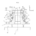
- FIG. 3 is a sectional explanatory view of the vehicle hub unit, showing a state where the measurement reference surfaces for the driven teeth shown in FIG. 2 are set.
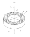
- FIG. 4 is a perspective view of the reference setting tool 50.
- the reference setting tool 50 is formed of an annular block, and has a plurality of reference teeth 53 on one end face in the direction along the central axis ⁇ thereof (bottom face of the reference setting tool 50 in FIG. 3 ).
- the reference teeth 53 are formed in imitation of the shape of the drive teeth 14 of the constant velocity joint 30, and are formed to have completely the same shape as the drive teeth 14 with dimensions that satisfy predetermined accuracies.
- an imaginary design reference surface ⁇ as shown in FIG.
- the reference teeth 53 are formed to have accurate dimensions, using the design reference surface ⁇ as a reference.
- the reference teeth 53 are aligned along the circular ring centering on the central axis ⁇ with a coaxiality that satisfies a predetermined accuracy.
- a hole 55 is formed along the central axis ⁇ of the reference setting tool 50.
- the other end face of the reference setting tool 50 in the direction along the central axis ⁇ (top face of the reference setting tool 50 in FIG. 3 ) is formed into a flat face.
- the other end face is perpendicular to the central axis ⁇ with a predetermined accuracy, and is formed parallel to the design reference surface ⁇ for the reference teeth 53 with a predetermined accuracy.
- the other end face of the reference setting tool 50 constitutes a first reference surface 51 that is used to measure the dimensions of the driven teeth 13.
- an outer periphery 52 of the reference setting tool 50 is formed in a cylindrical surface about the central axis ⁇ .
- the outer periphery 52 of the reference setting tool 50 is formed with a coaxiality and a circularity with respect to the central axis ⁇ with predetermined accuracies.
- the outer periphery 52 of the reference setting tool 50 constitutes a second reference surface that is used to measure the dimensions of the driven teeth 13.
- the hub unit 1 is set on a three-dimensional measuring machine 60 (an example of a measuring unit according to the invention) with the reference teeth 53 of the reference setting tool 50 in mesh with the driven teeth 13.
- the three-dimensional measuring machine 60 includes a surface plate 61, a portal frame 62, a slider 64, an elevating shaft 65, and a probe 67.
- the distal end of the probe 67 has a spherical gauge head 68.
- the portal frame 62 is provided so as to be movable in the longitudinal direction (Y direction) of the surface plate 61.
- the slider 64 is provided so as to be movable in the lateral direction (X direction) along a horizontal beam 63 of the portal frame 62.
- the elevating shaft 65 is provided on the slider 64 so as to be elevatable in the vertical direction (Z direction).
- the probe 67 is attached to the lower end of the elevating shaft 65 via a holder 66.
- the three-dimensional measuring machine 60 sequentially brings the gauge head 68 into contact with measured portions of a workpiece W while moving the probe 67 in three-dimensional directions (XYZ directions) to measure coordinate values at each contact point. Various dimensions of the workpiece W are obtained by computing the measured coordinate values.
- the three-dimensional measuring machine 60 may be a conventional commercially available machine.
- the hub unit 1 to which the reference setting tool 50 is attached is set on the surface plate 61, as the workpiece W.
- the gauge head 68 of the probe 67 is brought into contact with the first reference surface 51 and second reference surface 52 of the reference setting tool 50 to measure the coordinates of the first reference surface 51 and second reference surface 52.
- the first reference surface 51 and the second reference surface 52 are set as measurement reference surfaces (measurement reference positions) A and B at the time of measuring the dimensions of the driven teeth 13.
- the reference setting tool 50 is removed from the hub unit 1 on the surface plate 61, and then the gauge head 68 of the probe 67 is brought into contact with the driven teeth 13 of the side face spline 15 to measure various dimensions, such as the tooth flank, tooth trace and pitch of the driven teeth 13.
- the coordinates of the contact point at which the gauge head 68 contacts the driven teeth 13 are coordinates with reference to the measurement reference surfaces A and B respectively set by the first reference surface 51 and the second reference surface 52.
- the first reference surface 51 of the reference setting tool 50 is parallel to the design reference surface ⁇ (see FIG. 2 ) of the reference teeth 53, and is formed at a predetermined distance from the design reference surface ⁇ . Therefore, by meshing the reference teeth 53 of the reference setting tool 50 with the driven teeth 13 of the hub unit 1, the design reference surface ⁇ of the driven teeth 13 is replaced with the first reference surface 51 that is just shifted from the design reference surface ⁇ by a predetermined amount in the Z direction.
- the first reference surface 51 is used as the measurement reference surface A, and the shape of the driven teeth 13 is measured using the measurement reference surface A as a reference. In this way, further accurate measurement is possible, and it is possible to accurately check whether various dimensions of the driven teeth 13 satisfy the predetermined accuracies.
- the second reference surface 52 is used as the measurement reference surface B.
- the position (coordinates) of the central axis ⁇ (see FIG. 4 ) of the reference teeth 53 is obtained.
- the central axis ⁇ corresponds to the central axis of the driven teeth 13 in design. Therefore, by measuring the dimensions of the driven teeth 13 with respect to the central axis ⁇ , it is possible to accurately obtain the coaxiality, and the like, of the driven teeth 13 with respect to the imaginary central axis.
- the above-described measurement is carried out over all the driven teeth 13 of the side face spline 15, and is precise measurement that requires a certain period of time. Therefore, the above measurement is preferably carried out not over all the products but as sampling inspection in which part of products having the same model number are sampled and subjected to inspection. Further, 100% inspection in which all the products are subjected to inspection may be simply carried out with the use of the reference setting tool 50 according to a measuring method described below.
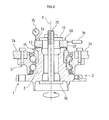
- FIG. 6 and FIG. 7 are sectional explanatory views of the vehicle hub unit, showing the measuring method in which the reference setting tool is set as a measuring object.
- the dimensions of the driven teeth 13 are not directly measured unlike in the above-described measuring method, and the reference setting tool 50, meshed with the driven teeth 13, is set as a measuring object.
- the guaranteed items are, for example, the runout of the driven teeth 13 in the direction along the axis O with respect to the outer ring 5 when the hub wheel 3 is rotated, the coaxiality (radial runout) of the driven teeth 13 with respect to the axis O of the hub wheel 3 in the same situation, the runout of the driven teeth 13 in the height direction with respect to the surface of the flange 7 of the hub wheel 3.
- the measuring method shown in FIG. 6 and FIG. 7 are executed.
- the reference setting tool 50 is fixed to the hub unit 1 with the reference setting tool 50 in mesh with the side face spline 15 of the hub unit 1.
- the hub wheel 3 and the reference setting tool 50 are held by a pair of clamping plates 70 and 71 coupled with a bolt 72.
- the outer ring 5 of the hub unit 1 is fixed to a fixing member 74.
- the hub wheel 3 is rotated one turn about the axis O with measuring tools 75 and 76, such as dial gauges, in contact with the first reference surface 51 and second reference surface 52 of the reference setting tool 50, respectively.
- the reference setting tool 50 also rotates one turn in accordance with the hub wheel 3, and the runout of the first reference surface 51 and the runout of the second reference surface 52 are respectively measured by the measuring tools 75 and 76.
- the runout of the first reference surface 51 corresponds to the runout of the driven teeth 13 in the direction along the axis O with respect to the outer ring 5 (the runout of the reference surface ⁇ ).
- the runout of the second reference surface 52 corresponds to the runout of the driven teeth 13 in the radial direction with respect to the rotation center (axis O) of the hub wheel 3 (coaxiality).
- the flange 7 of the hub wheel 3 of the hub unit 1 to which the reference setting tool 50 is fixed is placed on a rotary base 77.
- a block gauge 78 is adjusted to the size that is obtained by adding the height of the reference setting tool 50 (distance from the design reference surface ⁇ of the reference teeth 53 to the first reference surface 51) to the height from the flange 7 to the reference surface ⁇ for the driven teeth 13 in design, and is placed on the rotary base 77.
- a change in the height of the first reference surface 51 of the reference setting tool 50 at the time when the rotary base 77 is rotated one turn about the axis O is compared by a measuring tool 79, such as a dial gauge, with the height of the block gauge 78 to measure the runout of the design reference surface ⁇ for the driven teeth 13, which is replaced with the first reference surface 51.
- a measuring tool 79 such as a dial gauge
- the reference setting tool 50 has two reference surfaces, that is, the first reference surface 51 and the second reference surface 52.
- the reference setting tool 50 may have only one of the first reference surface 51 and the second reference surface 52.
- the reference surface may be other than the above-described first and second reference surfaces 51 and 52.
- an appropriate reference is set in order to measure the shape of the driven teeth to thereby make it possible to carry out accurate measurement.
Landscapes
- Physics & Mathematics (AREA)
- General Physics & Mathematics (AREA)
- Engineering & Computer Science (AREA)
- General Engineering & Computer Science (AREA)
- Mechanical Engineering (AREA)
- A Measuring Device Byusing Mechanical Method (AREA)
Abstract
Description
- The invention relates to a reference setting tool used to measure the shape of driven teeth (spline teeth) of a side face spline formed on a vehicle hub unit, a shape measuring device using the reference setting tool, and a shape measuring method using the reference setting tool.
- A hub unit is used to support a wheel of an automobile such that the wheel is rotatable with respect to a suspension. There is a known hub unit in which a side face spline having driven teeth (spline teeth) to be meshed with drive teeth, formed on an outer ring of a constant velocity joint, is formed on an axially inner end face (an end face on the inner side in the vehicle lateral direction) of a hub wheel to which a drive wheel is fitted (refer to, for example, Published Japanese Translation of
PCT Application No. 2008-536737 JP 2008-536737 A 2008-174178 JP 2008-174178 A - The driven teeth of the above-described side face spline need to satisfy predetermined accuracy requirements for various dimensions such as a tooth flank size, an arrangement pitch and a coaxiality with respect to the rotation center, in order to appropriately mesh the driven teeth with the drive teeth of the constant velocity joint. Therefore, after a hub unit is manufactured, an inspection process is carried out. In the inspection process, for example, a three-dimensional measuring device is used to measure various dimensions of the driven teeth, and whether predetermined accuracies are achieved is checked.
- The shape of the driven teeth of the side face spline is usually designed using a pitch surface when the driven teeth are in mesh with the drive teeth of the constant velocity joint, as a reference surface (e.g. an imaginary plane indicated by the long dashed double-short dashed line α in
FIG. 2 ; hereinafter, also referred to as "design reference surface"). However, because the design reference surface is just an imaginary plane, the design reference surface cannot be used to measure the shape of the driven teeth of an actual product in the inspection process. Therefore, in related art, various dimensions of spline teeth are measured using a worked surface, such as a flange surface and a wheel fitting surface of a hub wheel, as a temporary reference surface. However, this increases measurement errors, which makes it difficult to stably carry out accurate dimension measurement. - It is an object of the invention to provide a reference setting tool for measuring the shape of a side face spline, a side face spline shape measuring device using the reference setting tool, and a side face spline shape measuring method using the reference setting tool, which make it possible to set an appropriate reference for measuring the shape of driven teeth.
- An aspect of the invention relates to a reference setting tool for measuring the shape of a side face spline, which is used to measure the shape of driven teeth that are formed on an axial end face of a vehicle hub unit and that are meshed with drive teeth of a constant velocity joint. The reference setting tool includes: reference teeth that are formed so as to be aligned along a circular ring and so as to have the same shape as the drive teeth of the constant velocity joint; and a reference surface that has a predetermined correlation with the reference teeth, and that is used to set a reference position for measuring the shape of the driven teeth with the reference teeth in mesh with the driven teeth.
- Features, advantages, and technical and industrial significance of exemplary embodiments of the invention will be described below with reference to the accompanying drawings, in which like numerals denote like elements, and wherein:
-
FIG. 1 is a sectional view that shows a vehicle hub unit according to an embodiment of the invention; -
FIG. 2 is an enlarged sectional view of a clinched portion of the vehicle hub unit shown inFIG. 1 ; -
FIG. 3 is a sectional explanatory view of the vehicle hub unit, showing a state where measurement reference positions for driven teeth of an end portion of the clinched portion shown inFIG. 2 are set; -
FIG. 4 is a perspective view of a reference setting tool; -
FIG. 5 is a perspective view of a measuring device; -
FIG. 6 is a sectional explanatory view of the vehicle hub unit, showing a state where dimension measurement is carried out using the reference setting tool; and -
FIG. 7 is a sectional explanatory view of the vehicle hub unit, showing a state where dimension measurement is carried out using the reference setting tool. - Hereafter, an embodiment of the invention will be described in detail with reference to the accompanying drawings.
FIG. 1 is a sectional view that shows a vehicle hub unit according to the embodiment of the invention.FIG. 2 is an enlarged sectional view of a clinched portion of the vehicle hub unit. Thevehicle hub unit 1 supports a wheel of an automobile such that the wheel is rotatable with respect to a suspension. Thevehicle hub unit 1 includes ahub wheel 3, aninner ring member 4, anouter ring 5, and a plurality ofrolling elements 6. Thehub wheel 3 has acylindrical hub spindle 2. Theinner ring member 4 is fixed to an inner end portion, in the vehicle lateral direction (right end portion inFIG. 1 ), of thehub spindle 2 through clinching. Theouter ring 5 is arranged radially outward of thehub spindle 2. Therolling elements 6 are rollably arranged betweenouter ring raceways outer ring 5 andinner ring raceways hub spindle 2 and the outer periphery of theinner ring member 4, respectively. Therolling elements 6 are retained by acage 20 at predetermined intervals in the circumferential direction. In addition,seal members 21 are provided in an annular clearance formed between theouter ring 5 and thehub wheel 3. Theseal members 21 close the annular clearance at respective axial ends. - A
flange 7 is formed at an outer end portion in the vehicle lateral direction (left end portion inFIG. 1 ), of thehub wheel 3. Theflange 7 hasholes 7a into which bolts (not shown) are fitted. For example, a wheel of a tire and a brake disc are fitted to theflange 7 with the bolts. Afixing flange 8 is formed on the outer periphery of theouter ring 5. Thefixing flange 8 is used to fit thehub unit 1 to a vehicle body member (not shown) supported by the suspension of the vehicle. - The
hub spindle 2 is a single-piece member that has a large-diameter portion 9 and a small-diameter portion 11. The large-diameter portion 9 is formed on the flange 7-side. The small-diameter portion 11 is smaller in diameter than the large-diameter portion 9, and is contiguous with the large-diameter portion 9 via astep 10. Theinner ring raceway 2a is formed on the outer periphery of the large-diameter portion 9. Theinner ring raceway 2a corresponds to theouter ring raceway 5a of theouter ring 5. - The
inner ring member 4 is fitted to the outer periphery of the small-diameter portion 11 of thehub spindle 2, and end portion of the small-diameter portion 11 is then clinched. As a result, theinner ring member 4 is fixed between thestep 10 and a clinchedportion 12 of the small-diameter portion 11. - Torque of a
drive shaft 31 is transmitted to thehub unit 1 via aconstant velocity joint 30. Theconstant velocity joint 30 shown in the drawing is a Birfield constant velocity joint. Theconstant velocity joint 30 includes aninner ring 32, anouter ring 33, a plurality ofballs 34, and acage 35. Theinner ring 32 is securely fitted to one end of thedrive shaft 31. Theouter ring 33 is arranged radially outward of theinner ring 32. Theballs 34 are arranged between theinner ring 32 and theouter ring 33. Thecage 35 retains theballs 34. - The
outer ring 33 of theconstant velocity joint 30 has a generally bowl-shaped outer ringcylindrical portion 33a and an outerring shaft portion 33b. The outerring shaft portion 33b extends from the center portion of an end face of the outer ringcylindrical portion 33a. The outerring shaft portion 33b has ahole 36 that extends in the axial direction. The inner periphery of the outerring shaft portion 33b, which defines thehole 36, has an internal thread. Anexternal thread 37 of acap bolt 38 is screwed to the internal thread of the outerring shaft portion 33b. Thehub unit 1 is connected to the constant velocity joint 30 with thecap bolt 38. - As shown in
FIG. 2 , aside face spline 15 having a plurality of driven teeth (spline teeth) 13 is formed on an end face of the clinchedportion 12 of the inner end portion, in the vehicle lateral direction, of thehub spindle 2. The driventeeth 13 are formed so as to radiate from the axis O (seeFIG. 1 ) of thehub unit 1 while being aligned along a circular ring centering on the axis O.Multiple drive teeth 14 are formed on an end face of the outer ringcylindrical portion 33a, which faces the clinchedportion 12. Thedrive teeth 14 radiate from the axis of theouter ring 33 while being aligned along a circular ring centering on the axis of theouter ring 33. Due to the mesh of the driventeeth 13 and thedrive teeth 14, torque of thedrive shaft 31 is transmitted to thehub unit 1 via the constant velocity joint 30. Note that, the hatched region inFIG. 2 shows a meshingportion 16 at which the driventooth 13 and thedrive tooth 14 of the outer ringcylindrical portion 33a are in mesh with each other. In addition, inFIG. 2 , the tip and the root of the driventooth 13 are denoted by 13c and 13b, respectively, and the tip and the root of thedrive tooth 14 are denoted by 14c and 14b, respectively. - The number of the driven
teeth 13 is, for example, 37, and the number of thedrive teeth 14 is equal to the number of the driventeeth 13. The pitch surface (pitch line) α is set at a position at which the driventeeth 13 and thedrive teeth 14 are in mesh with each other. The dimensions of a tooth flank, a tooth trace, and the like, of each of the driventeeth 13 and thedrive teeth 14 are designed using the pitch surface α as a reference, and the driventeeth 13 and thedrive teeth 14 are formed by closed die forging. - The
hub unit 1 on which theside face spline 15 is formed is subjected to the inspection process after manufacturing. In the inspection process, various dimensions, such as the tooth flank shape, tooth trace and pitch of the driventeeth 13 are measured, and then whether these dimensions satisfy predetermined accuracies is checked. The dimensions such as the tooth flank shape of each driventooth 13 of theside face spline 15 are set using the pitch surface α (seeFIG. 2 ) as a reference surface in design. However, the reference surface α (hereinafter, also referred to as "design reference surface") is just an imaginary plane, so dimension measurement cannot be carried out using the design reference surface α as a reference in the inspection process. Therefore, in the present embodiment, in order to set an appropriate reference surface (measurement reference surface) that is an alternative to the design reference surface α, areference setting tool 50 described below is used. -
FIG. 3 is a sectional explanatory view of the vehicle hub unit, showing a state where the measurement reference surfaces for the driven teeth shown inFIG. 2 are set.FIG. 4 is a perspective view of thereference setting tool 50. Thereference setting tool 50 is formed of an annular block, and has a plurality ofreference teeth 53 on one end face in the direction along the central axis β thereof (bottom face of thereference setting tool 50 inFIG. 3 ). Thereference teeth 53 are formed in imitation of the shape of thedrive teeth 14 of the constant velocity joint 30, and are formed to have completely the same shape as thedrive teeth 14 with dimensions that satisfy predetermined accuracies. Thus, at thereference teeth 53 as well, an imaginary design reference surface α as shown inFIG. 2 is set, and thereference teeth 53 are formed to have accurate dimensions, using the design reference surface α as a reference. In addition, thereference teeth 53 are aligned along the circular ring centering on the central axis β with a coaxiality that satisfies a predetermined accuracy. In addition, ahole 55 is formed along the central axis β of thereference setting tool 50. - The other end face of the
reference setting tool 50 in the direction along the central axis β (top face of thereference setting tool 50 inFIG. 3 ) is formed into a flat face. The other end face is perpendicular to the central axis β with a predetermined accuracy, and is formed parallel to the design reference surface α for thereference teeth 53 with a predetermined accuracy. The other end face of thereference setting tool 50 constitutes afirst reference surface 51 that is used to measure the dimensions of the driventeeth 13. - In addition, an
outer periphery 52 of thereference setting tool 50 is formed in a cylindrical surface about the central axis β. In addition, theouter periphery 52 of thereference setting tool 50 is formed with a coaxiality and a circularity with respect to the central axis β with predetermined accuracies. Theouter periphery 52 of thereference setting tool 50 constitutes a second reference surface that is used to measure the dimensions of the driventeeth 13. - To measure the dimensions of the driven
teeth 13 of theside face spline 15 of thehub unit 1, thehub unit 1 is set on a three-dimensional measuring machine 60 (an example of a measuring unit according to the invention) with thereference teeth 53 of thereference setting tool 50 in mesh with the driventeeth 13. As shown inFIG. 5 , the three-dimensional measuring machine 60 includes asurface plate 61, aportal frame 62, aslider 64, an elevatingshaft 65, and aprobe 67. The distal end of theprobe 67 has aspherical gauge head 68. Theportal frame 62 is provided so as to be movable in the longitudinal direction (Y direction) of thesurface plate 61. Theslider 64 is provided so as to be movable in the lateral direction (X direction) along ahorizontal beam 63 of theportal frame 62. The elevatingshaft 65 is provided on theslider 64 so as to be elevatable in the vertical direction (Z direction). Theprobe 67 is attached to the lower end of the elevatingshaft 65 via aholder 66. - The three-
dimensional measuring machine 60 sequentially brings thegauge head 68 into contact with measured portions of a workpiece W while moving theprobe 67 in three-dimensional directions (XYZ directions) to measure coordinate values at each contact point. Various dimensions of the workpiece W are obtained by computing the measured coordinate values. The three-dimensional measuring machine 60 may be a conventional commercially available machine. - In the present embodiment, as shown in
FIG. 3 , thehub unit 1 to which thereference setting tool 50 is attached is set on thesurface plate 61, as the workpiece W. Thegauge head 68 of theprobe 67 is brought into contact with thefirst reference surface 51 andsecond reference surface 52 of thereference setting tool 50 to measure the coordinates of thefirst reference surface 51 andsecond reference surface 52. Thefirst reference surface 51 and thesecond reference surface 52 are set as measurement reference surfaces (measurement reference positions) A and B at the time of measuring the dimensions of the driventeeth 13. - Subsequently, the
reference setting tool 50 is removed from thehub unit 1 on thesurface plate 61, and then thegauge head 68 of theprobe 67 is brought into contact with the driventeeth 13 of theside face spline 15 to measure various dimensions, such as the tooth flank, tooth trace and pitch of the driventeeth 13. At this time, the coordinates of the contact point at which thegauge head 68 contacts the driventeeth 13 are coordinates with reference to the measurement reference surfaces A and B respectively set by thefirst reference surface 51 and thesecond reference surface 52. - The
first reference surface 51 of thereference setting tool 50 is parallel to the design reference surface α (seeFIG. 2 ) of thereference teeth 53, and is formed at a predetermined distance from the design reference surface α. Therefore, by meshing thereference teeth 53 of thereference setting tool 50 with the driventeeth 13 of thehub unit 1, the design reference surface α of the driventeeth 13 is replaced with thefirst reference surface 51 that is just shifted from the design reference surface α by a predetermined amount in the Z direction. Thefirst reference surface 51 is used as the measurement reference surface A, and the shape of the driventeeth 13 is measured using the measurement reference surface A as a reference. In this way, further accurate measurement is possible, and it is possible to accurately check whether various dimensions of the driventeeth 13 satisfy the predetermined accuracies. - In addition, the
second reference surface 52 is used as the measurement reference surface B. In this way, the position (coordinates) of the central axis β (seeFIG. 4 ) of thereference teeth 53 is obtained. When thereference teeth 53 are meshed with the driventeeth 13, the central axis β corresponds to the central axis of the driventeeth 13 in design. Therefore, by measuring the dimensions of the driventeeth 13 with respect to the central axis β, it is possible to accurately obtain the coaxiality, and the like, of the driventeeth 13 with respect to the imaginary central axis. - The above-described measurement is carried out over all the driven
teeth 13 of theside face spline 15, and is precise measurement that requires a certain period of time. Therefore, the above measurement is preferably carried out not over all the products but as sampling inspection in which part of products having the same model number are sampled and subjected to inspection. Further, 100% inspection in which all the products are subjected to inspection may be simply carried out with the use of thereference setting tool 50 according to a measuring method described below. -
FIG. 6 andFIG. 7 are sectional explanatory views of the vehicle hub unit, showing the measuring method in which the reference setting tool is set as a measuring object. In the measuring method shown inFIG. 6 andFIG. 7 , the dimensions of the driventeeth 13 are not directly measured unlike in the above-described measuring method, and thereference setting tool 50, meshed with the driventeeth 13, is set as a measuring object. - For the
side face spline 15 of thehub unit 1, several guaranteed items are set in order to accurately fit theside face spline 15 to thedrive teeth 14 of the constant velocity joint 30. The guaranteed items are, for example, the runout of the driventeeth 13 in the direction along the axis O with respect to theouter ring 5 when thehub wheel 3 is rotated, the coaxiality (radial runout) of the driventeeth 13 with respect to the axis O of thehub wheel 3 in the same situation, the runout of the driventeeth 13 in the height direction with respect to the surface of theflange 7 of thehub wheel 3. In order to inspect these guaranteed items, the measuring method shown inFIG. 6 andFIG. 7 are executed. - First, as shown in
FIG. 6 , thereference setting tool 50 is fixed to thehub unit 1 with thereference setting tool 50 in mesh with theside face spline 15 of thehub unit 1. In the present embodiment, thehub wheel 3 and thereference setting tool 50 are held by a pair of clampingplates bolt 72. Then, theouter ring 5 of thehub unit 1 is fixed to a fixingmember 74. - Then, the
hub wheel 3 is rotated one turn about the axis O with measuringtools first reference surface 51 andsecond reference surface 52 of thereference setting tool 50, respectively. In this way, thereference setting tool 50 also rotates one turn in accordance with thehub wheel 3, and the runout of thefirst reference surface 51 and the runout of thesecond reference surface 52 are respectively measured by themeasuring tools first reference surface 51 corresponds to the runout of the driventeeth 13 in the direction along the axis O with respect to the outer ring 5 (the runout of the reference surface α). In addition, the runout of thesecond reference surface 52 corresponds to the runout of the driventeeth 13 in the radial direction with respect to the rotation center (axis O) of the hub wheel 3 (coaxiality). - In addition, as shown in
FIG. 7 , theflange 7 of thehub wheel 3 of thehub unit 1 to which thereference setting tool 50 is fixed is placed on arotary base 77. Then, ablock gauge 78 is adjusted to the size that is obtained by adding the height of the reference setting tool 50 (distance from the design reference surface α of thereference teeth 53 to the first reference surface 51) to the height from theflange 7 to the reference surface α for the driventeeth 13 in design, and is placed on therotary base 77. Then, a change in the height of thefirst reference surface 51 of thereference setting tool 50 at the time when therotary base 77 is rotated one turn about the axis O is compared by a measuringtool 79, such as a dial gauge, with the height of theblock gauge 78 to measure the runout of the design reference surface α for the driventeeth 13, which is replaced with thefirst reference surface 51. - Therefore, in the measuring method shown in
FIG. 6 andFIG. 7 , even when the driventeeth 13 are not directly measured, it is possible to carry out inspection on the specific guaranteed items by measuring thefirst reference surface 51 andsecond reference surface 52 of thereference setting tool 50. - The invention is not limited to the above-described embodiment, and various modifications may be made as needed within the scope of the invention recited in the appended claims. For example, the
reference setting tool 50 according to the above embodiment has two reference surfaces, that is, thefirst reference surface 51 and thesecond reference surface 52. Alternatively, thereference setting tool 50 may have only one of thefirst reference surface 51 and thesecond reference surface 52. In addition, as long as a reference surface has a predetermined correlation with thereference teeth 53, the reference surface may be other than the above-described first and second reference surfaces 51 and 52. - According to the invention, an appropriate reference is set in order to measure the shape of the driven teeth to thereby make it possible to carry out accurate measurement.
Claims (7)
- A reference setting tool for measuring a shape of a side face spline, the reference setting tool being used to measure a shape of driven teeth that are formed on an axial end face of a vehicle hub unit and that are meshed with drive teeth of a constant velocity joint, comprising:reference teeth that are formed so as to be aligned along a circular ring and so as to have the same shape as the drive teeth of the constant velocity joint; anda reference surface that has a predetermined correlation with the reference teeth, and that is used to set a reference position for measuring the shape of the driven teeth with the reference teeth in mesh with the driven teeth.
- The reference setting tool according to claim 1, wherein the reference surface of the reference setting tool includes a first reference surface that is perpendicular to a central axis that is a center of the circular ring along which the reference teeth are aligned.
- The reference setting tool according to claim 1 or 2, wherein the reference surface of the reference setting tool includes a second reference surface formed of a cylindrical surface centering on a central axis that is a center of the circular ring along which the reference teeth are aligned.
- The reference setting tool according to any one of claims 1 to 3, wherein the reference surface is utilized as a measured surface of which a shape is measured by a measuring tool with the driven teeth in mesh with the drive teeth of the constant velocity joint.
- A shape measuring device for a side face spline, the shape measuring device measuring a shape of driven teeth that are formed on an axial end face of a vehicle hub unit and that are meshed with drive teeth of a constant velocity joint, comprising:the reference setting tool according to any one of claims 1 to 4; anda measuring unit that sets a measurement reference position using the reference surface with the reference teeth of the reference setting tool in mesh with the driven teeth of the vehicle hub unit, and that measures a shape of the driven teeth using the measurement reference position as a reference.
- A shape measuring method for a side face spline, for measuring a shape of driven teeth that are formed on an axial end face of a vehicle hub unit and that are meshed with drive teeth of a constant velocity joint, characterized by comprising:meshing the reference teeth of the reference setting tool according to any one of claims 1 to 4 with the driven teeth of the vehicle hub unit;setting a measurement reference position using the reference surface of the reference setting tool; andremoving the reference setting tool from the vehicle hub unit, and measuring a shape of the driven teeth using the measurement reference position as a reference.
- A shape measuring method for a side face spline, for measuring a shape of driven teeth that are formed on an axial end face of a vehicle hub unit and that are meshed with drive teeth of a constant velocity joint, characterized by comprising:meshing the reference teeth of the reference setting tool according to claim 4 with the driven teeth of the vehicle hub unit; androtating the driven teeth about an axis of the vehicle hub unit, and measuring a shape of the reference surface of the reference setting tool.
Applications Claiming Priority (1)
| Application Number | Priority Date | Filing Date | Title |
|---|---|---|---|
| JP2011188900A JP5870556B2 (en) | 2011-08-31 | 2011-08-31 | Side face spline shape measurement method |
Publications (2)
| Publication Number | Publication Date |
|---|---|
| EP2565579A1 true EP2565579A1 (en) | 2013-03-06 |
| EP2565579B1 EP2565579B1 (en) | 2016-12-14 |
Family
ID=46829623
Family Applications (1)
| Application Number | Title | Priority Date | Filing Date |
|---|---|---|---|
| EP12179454.9A Not-in-force EP2565579B1 (en) | 2011-08-31 | 2012-08-07 | Reference setting tool for measuring shape of side face spline and shape measuring method using the same |
Country Status (4)
| Country | Link |
|---|---|
| US (1) | US8869414B2 (en) |
| EP (1) | EP2565579B1 (en) |
| JP (1) | JP5870556B2 (en) |
| CN (1) | CN102967286B (en) |
Families Citing this family (13)
| Publication number | Priority date | Publication date | Assignee | Title |
|---|---|---|---|---|
| US8959785B2 (en) * | 2010-12-30 | 2015-02-24 | General Electric Company | Apparatus and method for measuring runout |
| JP5870556B2 (en) * | 2011-08-31 | 2016-03-01 | 株式会社ジェイテクト | Side face spline shape measurement method |
| JP5910480B2 (en) * | 2012-12-12 | 2016-04-27 | マツダ株式会社 | Center hole machining method and machining system for forged rotating body |
| WO2016050431A1 (en) * | 2014-10-01 | 2016-04-07 | Bayerische Motoren Werke Aktiengesellschaft | Assembly and method for the compressed air supply of a wheel of a vehicle |
| CN106705787A (en) * | 2016-12-01 | 2017-05-24 | 上海精智实业有限公司 | Disc hub bounce detection equipment |
| US10274303B2 (en) * | 2017-06-12 | 2019-04-30 | Ford Motor Company | Major diameter total runout gage for an external spline |
| CN109931832B (en) * | 2017-12-18 | 2021-06-01 | 中国航发沈阳黎明航空发动机有限责任公司 | Rapid measuring device and measuring method for position degree of large and complex integral precision casting casing |
| JP6762926B2 (en) * | 2017-12-18 | 2020-09-30 | 本田技研工業株式会社 | Vehicle wheel support |
| CN110081791A (en) * | 2019-04-30 | 2019-08-02 | 江苏神力齿轮冷挤有限公司 | A kind of output gear position degree detecting tool with internal tooth |
| CN112444181B (en) * | 2020-11-23 | 2022-03-01 | 苏州赛莱科斯工具有限公司 | Device and method for measuring space size of tooth palm |
| CN114353641B (en) * | 2021-10-29 | 2024-03-26 | 中国航发西安动力控制科技有限公司 | Blind hole spline coaxiality measuring method and measuring device thereof |
| CN114061401B (en) * | 2021-11-23 | 2024-02-06 | 西安陕鼓动力股份有限公司 | Method for detecting tooth height of straight tooth end face |
| CN115479575B (en) * | 2022-09-15 | 2024-08-30 | 湖南格润超导科技有限公司 | Coaxiality measuring device and method applied to superconducting magnet installation |
Citations (5)
| Publication number | Priority date | Publication date | Assignee | Title |
|---|---|---|---|---|
| US20080148893A1 (en) * | 2005-04-08 | 2008-06-26 | Schaeffler Kg | Collar Having End-Side Teeth For a Drivable Wheel Hub |
| JP2008174178A (en) | 2007-01-22 | 2008-07-31 | Jtekt Corp | Wheel support device |
| JP2008536737A (en) | 2005-03-04 | 2008-09-11 | シエフレル・コマンデイトゲゼルシヤフト | End face gear cutting part for wheel boss that can be driven |
| US20080240635A1 (en) * | 2005-08-04 | 2008-10-02 | Schaeffler Kg | Wheel Bearing Arrangement Having Spur Toothing |
| JP2010179327A (en) * | 2009-02-04 | 2010-08-19 | Honda Motor Co Ltd | Form rolling tool and spline shaft |
Family Cites Families (13)
| Publication number | Priority date | Publication date | Assignee | Title |
|---|---|---|---|---|
| US4583295A (en) * | 1985-04-10 | 1986-04-22 | Joseph A. Gresock | Spline gauging apparatus |
| JPH056481Y2 (en) * | 1985-04-24 | 1993-02-19 | ||
| JPH0619042Y2 (en) * | 1987-12-07 | 1994-05-18 | いすゞ自動車株式会社 | Jig for measuring inner spline pointing surface |
| JPH02114101A (en) * | 1988-10-24 | 1990-04-26 | Toshiba Corp | Apparatus for inspecting degree of parallelism |
| JPH0325335A (en) * | 1989-06-23 | 1991-02-04 | Mazda Motor Corp | Engagement testing device for gear |
| JP2609497B2 (en) * | 1992-11-30 | 1997-05-14 | 自動車部品工業株式会社 | Propeller shaft |
| JP2002206402A (en) * | 2001-01-12 | 2002-07-26 | Honda Motor Co Ltd | Assembling method of rotating member |
| US6598305B1 (en) * | 2002-02-22 | 2003-07-29 | Torque-Traction Technologies, Inc. | Spline gage system and method |
| JP2004257410A (en) * | 2003-02-24 | 2004-09-16 | Nsk Ltd | Quality inspection method for wheel bearing units |
| JP2007062647A (en) * | 2005-09-01 | 2007-03-15 | Ntn Corp | Bearing device for driving wheel |
| WO2008081879A1 (en) * | 2006-12-28 | 2008-07-10 | Jtekt Corporation | Wheel supporting device |
| JP5556509B2 (en) * | 2010-08-30 | 2014-07-23 | 株式会社ジェイテクト | Hub unit for vehicles |
| JP5870556B2 (en) * | 2011-08-31 | 2016-03-01 | 株式会社ジェイテクト | Side face spline shape measurement method |
-
2011
- 2011-08-31 JP JP2011188900A patent/JP5870556B2/en not_active Expired - Fee Related
-
2012
- 2012-07-31 US US13/562,962 patent/US8869414B2/en not_active Expired - Fee Related
- 2012-08-07 EP EP12179454.9A patent/EP2565579B1/en not_active Not-in-force
- 2012-08-31 CN CN201210320197.8A patent/CN102967286B/en not_active Expired - Fee Related
Patent Citations (5)
| Publication number | Priority date | Publication date | Assignee | Title |
|---|---|---|---|---|
| JP2008536737A (en) | 2005-03-04 | 2008-09-11 | シエフレル・コマンデイトゲゼルシヤフト | End face gear cutting part for wheel boss that can be driven |
| US20080148893A1 (en) * | 2005-04-08 | 2008-06-26 | Schaeffler Kg | Collar Having End-Side Teeth For a Drivable Wheel Hub |
| US20080240635A1 (en) * | 2005-08-04 | 2008-10-02 | Schaeffler Kg | Wheel Bearing Arrangement Having Spur Toothing |
| JP2008174178A (en) | 2007-01-22 | 2008-07-31 | Jtekt Corp | Wheel support device |
| JP2010179327A (en) * | 2009-02-04 | 2010-08-19 | Honda Motor Co Ltd | Form rolling tool and spline shaft |
Also Published As
| Publication number | Publication date |
|---|---|
| CN102967286B (en) | 2016-12-21 |
| EP2565579B1 (en) | 2016-12-14 |
| JP2013050402A (en) | 2013-03-14 |
| JP5870556B2 (en) | 2016-03-01 |
| CN102967286A (en) | 2013-03-13 |
| US20130047451A1 (en) | 2013-02-28 |
| US8869414B2 (en) | 2014-10-28 |
Similar Documents
| Publication | Publication Date | Title |
|---|---|---|
| US8869414B2 (en) | Reference setting tool for measuring shape of side face spline, shape measuring device using the same, and shape measuring method using the same | |
| JP6332572B1 (en) | Swing forging device inspection device, inspection tool, inspection method, bearing unit manufacturing device, bearing unit, and automobile manufacturing method | |
| JP2017015615A (en) | Position inspection device | |
| EP3330662B1 (en) | Pitch cone angle measurement method and pitch cone angle measurement device | |
| CN103267480B (en) | A kind of single flank engagement measuring apparatus of gear error | |
| EP3698102B1 (en) | Measuring device and measuring method for a grooved axially symmetric body | |
| CN101476855A (en) | Radial pulsation measurement instrument for external spline gear ring | |
| KR101193128B1 (en) | A center distance measuring device of rotating wheels with ball-bearings therein | |
| JP6699364B2 (en) | Ball screw device manufacturing method and steering device manufacturing method using ball screw device | |
| CN103630033A (en) | Saloon car transmission shaft fixed end cardan joint inner ring fairway sphere center position detecting device | |
| CN103712532A (en) | A method for detection and evaluation of shape and position errors for shells with skin frame-truss structures | |
| JP6070779B2 (en) | Side face spline shape measurement method | |
| JP5550529B2 (en) | Method for measuring the inner shape of tire molds | |
| CN105058269B (en) | Detect the holder of shock absorber pulley groove side circular runout | |
| US10274303B2 (en) | Major diameter total runout gage for an external spline | |
| CN201645260U (en) | On-line non-contact laser three-dimensional scanning detection device for internal thread of oil pipe coupling | |
| CN210374923U (en) | Motor center height measuring tool | |
| CN115741623A (en) | Open type cabin section inner cavity angle characteristic bench worker marking system and method | |
| CN115488442B (en) | Technological method for machining end teeth of locomotive traction gear shaft | |
| TWI910334B (en) | Multi-row bearings and bearing units | |
| CN105258589B (en) | A kind of measuring method of ring-shaped work pieces side-wall step hole parameter | |
| CN218864943U (en) | Differential mechanism planetary gear festival cone distance is with examining utensil | |
| CN114001615B (en) | Rapid detection device and detection method for automobile differential mechanism shell | |
| CN107806839B (en) | Portable precision taper measuring device | |
| CN210004937U (en) | Quick detection device for coaxiality of two holes of precision bearing |
Legal Events
| Date | Code | Title | Description |
|---|---|---|---|
| PUAI | Public reference made under article 153(3) epc to a published international application that has entered the european phase |
Free format text: ORIGINAL CODE: 0009012 |
|
| AK | Designated contracting states |
Kind code of ref document: A1 Designated state(s): AL AT BE BG CH CY CZ DE DK EE ES FI FR GB GR HR HU IE IS IT LI LT LU LV MC MK MT NL NO PL PT RO RS SE SI SK SM TR |
|
| AX | Request for extension of the european patent |
Extension state: BA ME |
|
| 17P | Request for examination filed |
Effective date: 20130906 |
|
| RBV | Designated contracting states (corrected) |
Designated state(s): AL AT BE BG CH CY CZ DE DK EE ES FI FR GB GR HR HU IE IS IT LI LT LU LV MC MK MT NL NO PL PT RO RS SE SI SK SM TR |
|
| RIC1 | Information provided on ipc code assigned before grant |
Ipc: G01B 21/04 20060101ALI20160513BHEP Ipc: G01B 5/16 20060101ALI20160513BHEP Ipc: G01B 21/00 20060101AFI20160513BHEP Ipc: G01B 3/00 20060101ALI20160513BHEP Ipc: G01B 5/008 20060101ALI20160513BHEP Ipc: G01B 5/00 20060101ALI20160513BHEP |
|
| GRAP | Despatch of communication of intention to grant a patent |
Free format text: ORIGINAL CODE: EPIDOSNIGR1 |
|
| RIN1 | Information on inventor provided before grant (corrected) |
Inventor name: KOUMOTO, MASASHI |
|
| INTG | Intention to grant announced |
Effective date: 20160624 |
|
| GRAS | Grant fee paid |
Free format text: ORIGINAL CODE: EPIDOSNIGR3 |
|
| GRAA | (expected) grant |
Free format text: ORIGINAL CODE: 0009210 |
|
| AK | Designated contracting states |
Kind code of ref document: B1 Designated state(s): AL AT BE BG CH CY CZ DE DK EE ES FI FR GB GR HR HU IE IS IT LI LT LU LV MC MK MT NL NO PL PT RO RS SE SI SK SM TR |
|
| REG | Reference to a national code |
Ref country code: GB Ref legal event code: FG4D |
|
| REG | Reference to a national code |
Ref country code: CH Ref legal event code: EP |
|
| REG | Reference to a national code |
Ref country code: IE Ref legal event code: FG4D |
|
| REG | Reference to a national code |
Ref country code: AT Ref legal event code: REF Ref document number: 853997 Country of ref document: AT Kind code of ref document: T Effective date: 20170115 |
|
| REG | Reference to a national code |
Ref country code: DE Ref legal event code: R096 Ref document number: 602012026528 Country of ref document: DE |
|
| PG25 | Lapsed in a contracting state [announced via postgrant information from national office to epo] |
Ref country code: LV Free format text: LAPSE BECAUSE OF FAILURE TO SUBMIT A TRANSLATION OF THE DESCRIPTION OR TO PAY THE FEE WITHIN THE PRESCRIBED TIME-LIMIT Effective date: 20161214 |
|
| REG | Reference to a national code |
Ref country code: LT Ref legal event code: MG4D |
|
| REG | Reference to a national code |
Ref country code: NL Ref legal event code: MP Effective date: 20161214 |
|
| PG25 | Lapsed in a contracting state [announced via postgrant information from national office to epo] |
Ref country code: GR Free format text: LAPSE BECAUSE OF FAILURE TO SUBMIT A TRANSLATION OF THE DESCRIPTION OR TO PAY THE FEE WITHIN THE PRESCRIBED TIME-LIMIT Effective date: 20170315 Ref country code: SE Free format text: LAPSE BECAUSE OF FAILURE TO SUBMIT A TRANSLATION OF THE DESCRIPTION OR TO PAY THE FEE WITHIN THE PRESCRIBED TIME-LIMIT Effective date: 20161214 Ref country code: NO Free format text: LAPSE BECAUSE OF FAILURE TO SUBMIT A TRANSLATION OF THE DESCRIPTION OR TO PAY THE FEE WITHIN THE PRESCRIBED TIME-LIMIT Effective date: 20170314 Ref country code: LT Free format text: LAPSE BECAUSE OF FAILURE TO SUBMIT A TRANSLATION OF THE DESCRIPTION OR TO PAY THE FEE WITHIN THE PRESCRIBED TIME-LIMIT Effective date: 20161214 |
|
| REG | Reference to a national code |
Ref country code: AT Ref legal event code: MK05 Ref document number: 853997 Country of ref document: AT Kind code of ref document: T Effective date: 20161214 |
|
| PG25 | Lapsed in a contracting state [announced via postgrant information from national office to epo] |
Ref country code: FI Free format text: LAPSE BECAUSE OF FAILURE TO SUBMIT A TRANSLATION OF THE DESCRIPTION OR TO PAY THE FEE WITHIN THE PRESCRIBED TIME-LIMIT Effective date: 20161214 Ref country code: RS Free format text: LAPSE BECAUSE OF FAILURE TO SUBMIT A TRANSLATION OF THE DESCRIPTION OR TO PAY THE FEE WITHIN THE PRESCRIBED TIME-LIMIT Effective date: 20161214 Ref country code: HR Free format text: LAPSE BECAUSE OF FAILURE TO SUBMIT A TRANSLATION OF THE DESCRIPTION OR TO PAY THE FEE WITHIN THE PRESCRIBED TIME-LIMIT Effective date: 20161214 |
|
| PG25 | Lapsed in a contracting state [announced via postgrant information from national office to epo] |
Ref country code: NL Free format text: LAPSE BECAUSE OF FAILURE TO SUBMIT A TRANSLATION OF THE DESCRIPTION OR TO PAY THE FEE WITHIN THE PRESCRIBED TIME-LIMIT Effective date: 20161214 |
|
| PG25 | Lapsed in a contracting state [announced via postgrant information from national office to epo] |
Ref country code: IS Free format text: LAPSE BECAUSE OF FAILURE TO SUBMIT A TRANSLATION OF THE DESCRIPTION OR TO PAY THE FEE WITHIN THE PRESCRIBED TIME-LIMIT Effective date: 20170414 Ref country code: SK Free format text: LAPSE BECAUSE OF FAILURE TO SUBMIT A TRANSLATION OF THE DESCRIPTION OR TO PAY THE FEE WITHIN THE PRESCRIBED TIME-LIMIT Effective date: 20161214 Ref country code: CZ Free format text: LAPSE BECAUSE OF FAILURE TO SUBMIT A TRANSLATION OF THE DESCRIPTION OR TO PAY THE FEE WITHIN THE PRESCRIBED TIME-LIMIT Effective date: 20161214 Ref country code: EE Free format text: LAPSE BECAUSE OF FAILURE TO SUBMIT A TRANSLATION OF THE DESCRIPTION OR TO PAY THE FEE WITHIN THE PRESCRIBED TIME-LIMIT Effective date: 20161214 Ref country code: RO Free format text: LAPSE BECAUSE OF FAILURE TO SUBMIT A TRANSLATION OF THE DESCRIPTION OR TO PAY THE FEE WITHIN THE PRESCRIBED TIME-LIMIT Effective date: 20161214 |
|
| PG25 | Lapsed in a contracting state [announced via postgrant information from national office to epo] |
Ref country code: SM Free format text: LAPSE BECAUSE OF FAILURE TO SUBMIT A TRANSLATION OF THE DESCRIPTION OR TO PAY THE FEE WITHIN THE PRESCRIBED TIME-LIMIT Effective date: 20161214 Ref country code: BG Free format text: LAPSE BECAUSE OF FAILURE TO SUBMIT A TRANSLATION OF THE DESCRIPTION OR TO PAY THE FEE WITHIN THE PRESCRIBED TIME-LIMIT Effective date: 20170314 Ref country code: PL Free format text: LAPSE BECAUSE OF FAILURE TO SUBMIT A TRANSLATION OF THE DESCRIPTION OR TO PAY THE FEE WITHIN THE PRESCRIBED TIME-LIMIT Effective date: 20161214 Ref country code: PT Free format text: LAPSE BECAUSE OF FAILURE TO SUBMIT A TRANSLATION OF THE DESCRIPTION OR TO PAY THE FEE WITHIN THE PRESCRIBED TIME-LIMIT Effective date: 20170414 Ref country code: BE Free format text: LAPSE BECAUSE OF FAILURE TO SUBMIT A TRANSLATION OF THE DESCRIPTION OR TO PAY THE FEE WITHIN THE PRESCRIBED TIME-LIMIT Effective date: 20161214 Ref country code: ES Free format text: LAPSE BECAUSE OF FAILURE TO SUBMIT A TRANSLATION OF THE DESCRIPTION OR TO PAY THE FEE WITHIN THE PRESCRIBED TIME-LIMIT Effective date: 20161214 Ref country code: AT Free format text: LAPSE BECAUSE OF FAILURE TO SUBMIT A TRANSLATION OF THE DESCRIPTION OR TO PAY THE FEE WITHIN THE PRESCRIBED TIME-LIMIT Effective date: 20161214 Ref country code: IT Free format text: LAPSE BECAUSE OF FAILURE TO SUBMIT A TRANSLATION OF THE DESCRIPTION OR TO PAY THE FEE WITHIN THE PRESCRIBED TIME-LIMIT Effective date: 20161214 |
|
| REG | Reference to a national code |
Ref country code: DE Ref legal event code: R097 Ref document number: 602012026528 Country of ref document: DE |
|
| PLBE | No opposition filed within time limit |
Free format text: ORIGINAL CODE: 0009261 |
|
| STAA | Information on the status of an ep patent application or granted ep patent |
Free format text: STATUS: NO OPPOSITION FILED WITHIN TIME LIMIT |
|
| 26N | No opposition filed |
Effective date: 20170915 |
|
| PG25 | Lapsed in a contracting state [announced via postgrant information from national office to epo] |
Ref country code: DK Free format text: LAPSE BECAUSE OF FAILURE TO SUBMIT A TRANSLATION OF THE DESCRIPTION OR TO PAY THE FEE WITHIN THE PRESCRIBED TIME-LIMIT Effective date: 20161214 |
|
| PG25 | Lapsed in a contracting state [announced via postgrant information from national office to epo] |
Ref country code: SI Free format text: LAPSE BECAUSE OF FAILURE TO SUBMIT A TRANSLATION OF THE DESCRIPTION OR TO PAY THE FEE WITHIN THE PRESCRIBED TIME-LIMIT Effective date: 20161214 |
|
| REG | Reference to a national code |
Ref country code: CH Ref legal event code: PL |
|
| PG25 | Lapsed in a contracting state [announced via postgrant information from national office to epo] |
Ref country code: MC Free format text: LAPSE BECAUSE OF FAILURE TO SUBMIT A TRANSLATION OF THE DESCRIPTION OR TO PAY THE FEE WITHIN THE PRESCRIBED TIME-LIMIT Effective date: 20161214 |
|
| GBPC | Gb: european patent ceased through non-payment of renewal fee |
Effective date: 20170807 |
|
| PG25 | Lapsed in a contracting state [announced via postgrant information from national office to epo] |
Ref country code: LI Free format text: LAPSE BECAUSE OF NON-PAYMENT OF DUE FEES Effective date: 20170831 Ref country code: CH Free format text: LAPSE BECAUSE OF NON-PAYMENT OF DUE FEES Effective date: 20170831 |
|
| REG | Reference to a national code |
Ref country code: FR Ref legal event code: ST Effective date: 20180430 |
|
| REG | Reference to a national code |
Ref country code: IE Ref legal event code: MM4A |
|
| PG25 | Lapsed in a contracting state [announced via postgrant information from national office to epo] |
Ref country code: LU Free format text: LAPSE BECAUSE OF NON-PAYMENT OF DUE FEES Effective date: 20170807 |
|
| PG25 | Lapsed in a contracting state [announced via postgrant information from national office to epo] |
Ref country code: IE Free format text: LAPSE BECAUSE OF NON-PAYMENT OF DUE FEES Effective date: 20170807 Ref country code: GB Free format text: LAPSE BECAUSE OF NON-PAYMENT OF DUE FEES Effective date: 20170807 |
|
| PG25 | Lapsed in a contracting state [announced via postgrant information from national office to epo] |
Ref country code: FR Free format text: LAPSE BECAUSE OF NON-PAYMENT OF DUE FEES Effective date: 20170831 |
|
| PG25 | Lapsed in a contracting state [announced via postgrant information from national office to epo] |
Ref country code: MT Free format text: LAPSE BECAUSE OF NON-PAYMENT OF DUE FEES Effective date: 20170807 |
|
| PG25 | Lapsed in a contracting state [announced via postgrant information from national office to epo] |
Ref country code: HU Free format text: LAPSE BECAUSE OF FAILURE TO SUBMIT A TRANSLATION OF THE DESCRIPTION OR TO PAY THE FEE WITHIN THE PRESCRIBED TIME-LIMIT; INVALID AB INITIO Effective date: 20120807 |
|
| PG25 | Lapsed in a contracting state [announced via postgrant information from national office to epo] |
Ref country code: CY Free format text: LAPSE BECAUSE OF NON-PAYMENT OF DUE FEES Effective date: 20161214 |
|
| PG25 | Lapsed in a contracting state [announced via postgrant information from national office to epo] |
Ref country code: MK Free format text: LAPSE BECAUSE OF FAILURE TO SUBMIT A TRANSLATION OF THE DESCRIPTION OR TO PAY THE FEE WITHIN THE PRESCRIBED TIME-LIMIT Effective date: 20161214 |
|
| PG25 | Lapsed in a contracting state [announced via postgrant information from national office to epo] |
Ref country code: TR Free format text: LAPSE BECAUSE OF FAILURE TO SUBMIT A TRANSLATION OF THE DESCRIPTION OR TO PAY THE FEE WITHIN THE PRESCRIBED TIME-LIMIT Effective date: 20161214 |
|
| PG25 | Lapsed in a contracting state [announced via postgrant information from national office to epo] |
Ref country code: AL Free format text: LAPSE BECAUSE OF FAILURE TO SUBMIT A TRANSLATION OF THE DESCRIPTION OR TO PAY THE FEE WITHIN THE PRESCRIBED TIME-LIMIT Effective date: 20161214 |
|
| PGFP | Annual fee paid to national office [announced via postgrant information from national office to epo] |
Ref country code: DE Payment date: 20210630 Year of fee payment: 10 |
|
| REG | Reference to a national code |
Ref country code: DE Ref legal event code: R119 Ref document number: 602012026528 Country of ref document: DE |
|
| PG25 | Lapsed in a contracting state [announced via postgrant information from national office to epo] |
Ref country code: DE Free format text: LAPSE BECAUSE OF NON-PAYMENT OF DUE FEES Effective date: 20230301 |