EP2565491A2 - Spring damper device for a bicycle - Google Patents
Spring damper device for a bicycle Download PDFInfo
- Publication number
- EP2565491A2 EP2565491A2 EP12181817A EP12181817A EP2565491A2 EP 2565491 A2 EP2565491 A2 EP 2565491A2 EP 12181817 A EP12181817 A EP 12181817A EP 12181817 A EP12181817 A EP 12181817A EP 2565491 A2 EP2565491 A2 EP 2565491A2
- Authority
- EP
- European Patent Office
- Prior art keywords
- spring
- damper
- valve
- piston
- damper device
- Prior art date
- Legal status (The legal status is an assumption and is not a legal conclusion. Google has not performed a legal analysis and makes no representation as to the accuracy of the status listed.)
- Granted
Links
Images


Classifications
-
- F—MECHANICAL ENGINEERING; LIGHTING; HEATING; WEAPONS; BLASTING
- F16—ENGINEERING ELEMENTS AND UNITS; GENERAL MEASURES FOR PRODUCING AND MAINTAINING EFFECTIVE FUNCTIONING OF MACHINES OR INSTALLATIONS; THERMAL INSULATION IN GENERAL
- F16F—SPRINGS; SHOCK-ABSORBERS; MEANS FOR DAMPING VIBRATION
- F16F9/00—Springs, vibration-dampers, shock-absorbers, or similarly-constructed movement-dampers using a fluid or the equivalent as damping medium
- F16F9/32—Details
- F16F9/50—Special means providing automatic damping adjustment, i.e. self-adjustment of damping by particular sliding movements of a valve element, other than flexions or displacement of valve discs; Special means providing self-adjustment of spring characteristics
- F16F9/512—Means responsive to load action, i.e. static load on the damper or dynamic fluid pressure changes in the damper, e.g. due to changes in velocity
-
- B—PERFORMING OPERATIONS; TRANSPORTING
- B62—LAND VEHICLES FOR TRAVELLING OTHERWISE THAN ON RAILS
- B62K—CYCLES; CYCLE FRAMES; CYCLE STEERING DEVICES; RIDER-OPERATED TERMINAL CONTROLS SPECIALLY ADAPTED FOR CYCLES; CYCLE AXLE SUSPENSIONS; CYCLE SIDE-CARS, FORECARS, OR THE LIKE
- B62K25/00—Axle suspensions
- B62K25/04—Axle suspensions for mounting axles resiliently on cycle frame or fork
- B62K25/06—Axle suspensions for mounting axles resiliently on cycle frame or fork with telescopic fork, e.g. including auxiliary rocking arms
- B62K25/10—Axle suspensions for mounting axles resiliently on cycle frame or fork with telescopic fork, e.g. including auxiliary rocking arms for rear wheel
-
- F—MECHANICAL ENGINEERING; LIGHTING; HEATING; WEAPONS; BLASTING
- F16—ENGINEERING ELEMENTS AND UNITS; GENERAL MEASURES FOR PRODUCING AND MAINTAINING EFFECTIVE FUNCTIONING OF MACHINES OR INSTALLATIONS; THERMAL INSULATION IN GENERAL
- F16F—SPRINGS; SHOCK-ABSORBERS; MEANS FOR DAMPING VIBRATION
- F16F9/00—Springs, vibration-dampers, shock-absorbers, or similarly-constructed movement-dampers using a fluid or the equivalent as damping medium
- F16F9/02—Springs, vibration-dampers, shock-absorbers, or similarly-constructed movement-dampers using a fluid or the equivalent as damping medium using gas only or vacuum
- F16F9/0209—Telescopic
-
- F—MECHANICAL ENGINEERING; LIGHTING; HEATING; WEAPONS; BLASTING
- F16—ENGINEERING ELEMENTS AND UNITS; GENERAL MEASURES FOR PRODUCING AND MAINTAINING EFFECTIVE FUNCTIONING OF MACHINES OR INSTALLATIONS; THERMAL INSULATION IN GENERAL
- F16F—SPRINGS; SHOCK-ABSORBERS; MEANS FOR DAMPING VIBRATION
- F16F9/00—Springs, vibration-dampers, shock-absorbers, or similarly-constructed movement-dampers using a fluid or the equivalent as damping medium
- F16F9/32—Details
- F16F9/34—Special valve constructions; Shape or construction of throttling passages
- F16F9/3405—Throttling passages in or on piston body, e.g. slots
-
- F—MECHANICAL ENGINEERING; LIGHTING; HEATING; WEAPONS; BLASTING
- F16—ENGINEERING ELEMENTS AND UNITS; GENERAL MEASURES FOR PRODUCING AND MAINTAINING EFFECTIVE FUNCTIONING OF MACHINES OR INSTALLATIONS; THERMAL INSULATION IN GENERAL
- F16F—SPRINGS; SHOCK-ABSORBERS; MEANS FOR DAMPING VIBRATION
- F16F9/00—Springs, vibration-dampers, shock-absorbers, or similarly-constructed movement-dampers using a fluid or the equivalent as damping medium
- F16F9/32—Details
- F16F9/34—Special valve constructions; Shape or construction of throttling passages
- F16F9/348—Throttling passages in the form of annular discs or other plate-like elements which may or may not have a spring action, operating in opposite directions or singly, e.g. annular discs positioned on top of the valve or piston body
-
- F—MECHANICAL ENGINEERING; LIGHTING; HEATING; WEAPONS; BLASTING
- F16—ENGINEERING ELEMENTS AND UNITS; GENERAL MEASURES FOR PRODUCING AND MAINTAINING EFFECTIVE FUNCTIONING OF MACHINES OR INSTALLATIONS; THERMAL INSULATION IN GENERAL
- F16F—SPRINGS; SHOCK-ABSORBERS; MEANS FOR DAMPING VIBRATION
- F16F9/00—Springs, vibration-dampers, shock-absorbers, or similarly-constructed movement-dampers using a fluid or the equivalent as damping medium
- F16F9/32—Details
- F16F9/44—Means on or in the damper for manual or non-automatic adjustment; such means combined with temperature correction
- F16F9/46—Means on or in the damper for manual or non-automatic adjustment; such means combined with temperature correction allowing control from a distance, i.e. location of means for control input being remote from site of valves, e.g. on damper external wall
- F16F9/461—Means on or in the damper for manual or non-automatic adjustment; such means combined with temperature correction allowing control from a distance, i.e. location of means for control input being remote from site of valves, e.g. on damper external wall characterised by actuation means
-
- F—MECHANICAL ENGINEERING; LIGHTING; HEATING; WEAPONS; BLASTING
- F16—ENGINEERING ELEMENTS AND UNITS; GENERAL MEASURES FOR PRODUCING AND MAINTAINING EFFECTIVE FUNCTIONING OF MACHINES OR INSTALLATIONS; THERMAL INSULATION IN GENERAL
- F16F—SPRINGS; SHOCK-ABSORBERS; MEANS FOR DAMPING VIBRATION
- F16F9/00—Springs, vibration-dampers, shock-absorbers, or similarly-constructed movement-dampers using a fluid or the equivalent as damping medium
- F16F9/32—Details
- F16F9/44—Means on or in the damper for manual or non-automatic adjustment; such means combined with temperature correction
- F16F9/46—Means on or in the damper for manual or non-automatic adjustment; such means combined with temperature correction allowing control from a distance, i.e. location of means for control input being remote from site of valves, e.g. on damper external wall
- F16F9/466—Throttling control, i.e. regulation of flow passage geometry
- F16F9/469—Valves incorporated in the piston
-
- B—PERFORMING OPERATIONS; TRANSPORTING
- B62—LAND VEHICLES FOR TRAVELLING OTHERWISE THAN ON RAILS
- B62K—CYCLES; CYCLE FRAMES; CYCLE STEERING DEVICES; RIDER-OPERATED TERMINAL CONTROLS SPECIALLY ADAPTED FOR CYCLES; CYCLE AXLE SUSPENSIONS; CYCLE SIDE-CARS, FORECARS, OR THE LIKE
- B62K25/00—Axle suspensions
- B62K25/04—Axle suspensions for mounting axles resiliently on cycle frame or fork
- B62K2025/047—Axle suspensions for mounting axles resiliently on cycle frame or fork with suspension locking means
Definitions
- a variety of spring-damper devices for bicycles are known.
- a spring device is conventionally provided, which is an air or steel spring device, in order to absorb impact forces of the rear swing arm occurring in the use of the bicycle.
- a damper device is usually provided.
- a valve at low impact speeds ie a low displacement speed of the damper body, and thus open at relatively low pressure differences between the damper chambers
- the second valve in addition to strong shocks or higher Shifting speeds of the damper body and thus can open larger pressure differences.
- the third valve can then serve as overload protection and be opened in very strong shocks and thus very high displacement velocities of the damper body in addition to the other two valves.
- the second valve thus controls in particular medium and fast displacement movements of the damper body.
- the damper piston is arranged on a guide rod which is fastened to the housing, wherein the damper piston then separates a cylinder from an annular space in the damper body and the valves each controlling a volume flow of the fluid in the damper body, which flows through the damper piston.
- the second valve has a encompassed by the valve body of the first valve and fixed to the guide rod spring washer. This is in particular in the closed state on the end face of the damper piston and is elastically deformed with sections of the damper piston due to pressure forces of the fluid in the damper body at a certain pressure difference between the cylinder and annulus and here is a introduced in the damper piston second connection recess between the Cylinder and annulus free. This is also an extremely constructed and inexpensive valve.
- a spring damper device for a bicycle has a fixable housing on which a spring tube of an air spring device is fixedly arranged.
- a gas piston is guided for air suspension, which is displaceable in the spring tube via a connectable to a damping element, such as a rear swing arm, damper body of a damper device.
- the gas piston delimited together with the spring tube an air space, wherein advantageously a volume of the air space by the size of a fixable on the housing and arranged in the air space spacer is determined. hereby During assembly, the volume of the air space can be varied by the size of the spacer used.
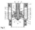
- valves in the region of the damper piston 24 are based on the FIG. 2 explained in more detail.
- FIG. 2 shows a section of the spring-damper device 1 from FIG. 1 in the region of the damper piston 24.
- the gas piston 10 is in this view together with the damper body 12 in the direction of the housing 2 from FIG. 1 postponed.
- the shift is the result of a force surge of the rear wheel axle, which via the eyelet 22 in FIG. 1 is transmitted to the damper body 12 and via this on the gas piston 10, whereby the gas piston 10 with the damper body 12 in the direction of reduction of an air-filled annular space 52 of the air cylinder 6 from FIG. 1 shifts to cushion this impact force by air suspension.
- To damp this air suspension of the damper piston 24 is off FIG. 2 provided with three valves 54, 56 and 58, which control a volume flow of a fluid from the cylinder chamber 28 to the annular space 30 of the damper piston 24.
- the valve 56 has an annular valve body 84 which is guided with its inner circumferential surface on an outer circumferential surface of the guide ring 76 axially displaceable. With a valve surface facing the damper piston 24, the valve surface essentially abuts against the end face 74 of the damper piston 24 in the closed state.
- the annular valve body 84 is extended in the axial direction by an annular support collar 86 and, viewed in the longitudinal direction, has a greater width than the guide ring 76.
- the spring washer 96 is bent away elastically from the valve member 94, whereby an opening cross section for a volume flow of the fluid between the cylinder chamber 28 and the annular space 30 is released.
- a further washer is arranged, which bears against an annular end face of the guide rod 26.
- valve 58 which serves in addition to the valves 54 and 56 in exceeding a certain pressure difference between the cylinder chamber 28 and the annular space 30th opens.
- an opening cross-section for a volume flow between the cylinder chamber 28 and the annular space 30 is further increased, whereby the load acting on the spring-damper device 1 is reduced.
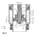
- Valve 106 has a spring washer 110 fixed to valve member 62. It is mounted on an axial projection of valve member 62 facing away from damper piston 24 and fixed with a nut 112 threaded onto the axial projection.
- the spring disk 110 closes in the closed state inclined bores, which are introduced to the transverse leg 114 of the valve member 62 and open into the axial through-bore 98.
- the through-bore 98 of the valve piece 62 terminates in an annular space 116 of the guide rod 26.
- the annular space is bounded by an end face of the valve member 62 and is fluidly connected via an introduced into the guide rod 26 oblique bore 118 with the annular space 30 of the damper body 12.
- a pressure relief valve is provided, which releases such a large opening cross-section for the volume flow, that a damping force does not increase further.
- a load of the spring-damper device is low, but this can lead to a blow of the spring damper device disadvantageous in strong shocks of a rear swingarm.
- the curve 134 is constructed in three parts in contrast to the curves 130 and 132.
- the valve 54 acts in the compression phase FIG. 2 , and thus in a slow speed range. If the speed continues to rise, for example up to 4 cm / s, the valve 56 opens in the FIG. 2 , whereby the compression forces increase less than in the slow speed range. After this average speed range from about 4 cm / s then opens the third valve 58 to further reduce the increase in compression forces.
- a speed-damping force curve can be set comparatively fine.
- the spring-damper device 1 off FIG. 1 is characterized by its flexible adjustability and in particular by its flexibility in the initial setup, ie, during its assembly. By simply changing the number of spring washers of the respective valves, a variety of desired damping characteristics can be achieved without the need for further changes in the spring damper device 1. Extremely advantageous in the present spring-damper device 1 is a two-stage overload protection by the two valves 56 and 58 of the FIG. 2 , It should be noted that in the closed or semi-closed state of the compression valve body 70 shocks may occur in the use of a bicycle with the spring-damper device of up to 2 m / s.
- the valves 56 and 58 are used FIG. 2 as overload protection.
- this overload protection is difficult to adjust due to a single valve. If the valve is set too low, ie it opens even at low pressure differences, in order to obtain a sensitive response, the probability of a breakthrough increases. If, on the other hand, the overload protection is set too high, then the chassis in the middle speed range of the spring-damper device 1, which is the most driven condition, becomes very insensitive.
- the present spring-damper device 1 has a "tripartition" of the damping characteristic in order to be able to respond to low-speed (lowspeed dampening), medium (midspeed dampening) and high-speed (high-speed damping).
- the high-speed compression damping unit is split into the two valves 56 and 58 FIG. 2 ,
- the valve 56 is intended in particular to regulate a volume flow of the fluid and the thrust reversal at medium and fast compression speeds.
- the volume flow is often insufficient in extreme situations, whereby the spring-damper device 1 is either heavily loaded in tight attenuation tuning or tends to soft vote for strike through.
Abstract
Description
Die Erfindung betrifft eine Feder-Dämpfervorrichtung für ein Fahrrad gemäß dem Oberbegriff des Patentanspruchs 1, 13 oder 15.The invention relates to a spring-damper device for a bicycle according to the preamble of claim 1, 13 or 15.
Aus dem Stand der Technik sind eine Vielzahl von Feder-Dämpfervorrichtungen für Fahrräder bekannt. Zur Federung einer Hinterradschwinge eines Fahrrads ist üblicher Weise eine Federeinrichtung vorgesehen, bei der es sich um eine Luft- oder Stahlfedereinrichtung handelt, um im Einsatz des Fahrrads auftretende Stoßkräfte der Hinterradschwinge abzufedern. Zum Steuern der Feder, insbesondere um diese zu Dämpfen, ist in der Regel eine Dämpfereinrichtung vorgesehen.From the prior art, a variety of spring-damper devices for bicycles are known. For suspension of a rear swing arm of a bicycle, a spring device is conventionally provided, which is an air or steel spring device, in order to absorb impact forces of the rear swing arm occurring in the use of the bicycle. For controlling the spring, in particular to damp these, a damper device is usually provided.
In der
Nachteilig hierbei ist, dass schon bei vergleichsweise geringen Druckdifferenzen öffnet ein Durchschlag der Feder-Dämpfervorrichtung erfolgen kann, d. h., dass der Gaskolben auf das Gehäuse auftrifft, wodurch Beschädigungen auftreten können. Wird dagegen dass es erst bei vergleichsweise hohen Druckdifferenzen öffnet, so wird zwar ein Durchschlagen in der Regel vermieden, allerdings können hierdurch äußerst starke Druckkräfte in der Dämpfereinrichtung auftreten was ebenfalls zur Beschädigung führen kann. Des Weiteren ist im letzteren Fall nachteilig, dass das Fahrwerk des Fahrrads, insbesondere die Hinterradschwinge bei höheren Geschwindigkeiten sehr unsensibel reagiert, was zu einem Traktionsverlust führen kann.The disadvantage here is that even at comparatively low pressure differences opens a breakdown of the spring-damper device can be done, d. h., That the gas piston impinges on the housing, whereby damage can occur. If, on the other hand, it opens only at comparatively high pressure differences, penetration is generally avoided, but this can result in extremely strong pressure forces in the damper device, which can likewise lead to damage. Furthermore, it is disadvantageous in the latter case that the chassis of the bicycle, in particular the rear swing arm at high speeds reacts very insensitive, which can lead to a loss of traction.
Dem gegenüber liegt der Erfindung die Aufgabe zugrunde, eine Feder-Dämpfervorrichtung zu schaffen, die die genannten Nachteile überwindet.In contrast, the invention has for its object to provide a spring-damper device which overcomes the disadvantages mentioned.
Diese Aufgabe wird gelöst durch eine Feder-Dämpfervorrichtung gemäß den Merkmalen des Patentanspruchs 1. Sonstige vorteilhafte Weiterbildungen der Erfindung sind Gegenstand weiterer Unteransprüche.This object is achieved by a spring-damper device according to the features of claim 1. Other advantageous developments of the invention are the subject of further sub-claims.
Erfindungsgemäß hat eine Feder-Dämpfervorrichtung für ein Fahrrad ein, insbesondere an einem Fahrradrahmen, festlegbares Gehäuse. An diesem ist eine Federeinrichtung abstützbar, wobei es sich bei der Federeinrichtung insbesondere um eine Luftfedereinrichtung und/oder um eine Stahlfedereinrichtung handelt. Die Federeinrichtung ist über einen Dämpferkörper einer Dämpfereinrichtung in einer Federrichtung spannbar. Der Dämpferkörper ist hierbei mit einem zu dämpfenden Element, beispielsweise einer Hinterradschwinge des Fahrrads, verbunden. In dem Dämpferkörper ist ein fest am Gehäuse insbesondere über eine Führungsstange festgelegter Dämpferkolben verschiebbar geführt. Mit dem Dämpferkolben wird der Dämpferkörper in zwei Dämpferräume geteilt. Zur Dämpfung einer Federung der Federeinrichtung durch die Dämpfereinrichtung, weist diese drei Ventile auf, bei denen es sich insbesondere um Druckbegrenzungsventile handelt. Mit diesen Ventilen ist ein Volumenstrom eines Fluids zwischen den Dämpfungsräumen beim Spannen der Federeinrichtung in Federrichtung steuerbar, wodurch wiederum Dämpfungskräfte der Dämpfereinrichtung gesteuert sind. Diese Lösung hat den Vorteil, dass die Ventile bei unterschiedlichen Druckdifferenzen zwischen den Dämpferräumen öffnen können, wodurch gewünschte Dämpfungskräfte der Dämpfvorrichtung, im Vergleich zum Stand der Technik, der nur zwei Ventile aufweist, besser eingestellt werden können. Bei Auftreten eines Stoßes der durch die Feder-Dämpfervorrichtung abgefedert wird, kann dann ein Ventil bei geringen Stoßgeschwindigkeiten, d. h. einer geringen Verschiebegeschwindigkeit des Dämpferkörpers, und somit bei vergleichsweise geringen Druckdifferenzen zwischen den Dämpferräumen öffnen, während das zweite Ventil zusätzlich bei stärken Stößen bzw. höheren Verschiebegeschwindigkeiten des Dämpferkörpers und somit größeren Druckdifferenzen öffnen kann. Das dritte Ventil kann dann als Überlastungsschutz dienen und bei sehr starken Stößen und somit sehr hohen Verschiebegeschwindigkeiten des Dämpferkörpers zusätzlich zu den beiden anderen Ventilen geöffnet werden. Das zweite Ventil regelt somit insbesondere mittlere und schnelle Verschiebebewegungen des Dämpferkörpers. Ein Öffnungsquerschnitt des zweiten Ventils kann geringer als im Stand der Technik sein, da bei äußerst hohen Geschwindigkeiten des Dämpferkörpers zusätzlich das dritte Ventil öffnet, um einen hohen Volumenstrom zwischen den Dämpferräumen zum Abbau der Druckbelastung zu ermöglichen. Da die beiden Ventile somit im Vergleich zum Stand der Technik jeweils einen geringeren Strömungsquerschnitt freigeben und nur gemeinsam einen mit dem Stand der Technik vergleichbaren Strömungsquerschnitt freigeben, können diese am Ende der Verschiebebewegung des Dämpferkörpers jeweils vergleichsweise schnell schließen, wodurch eine Schubumkehr der Feder-Dämpfervorrichtung äußerst schnell erfolgt.According to the invention, a spring damper device for a bicycle, in particular on a bicycle frame, fixable housing. At this a spring device can be supported, wherein it is the spring device in particular an air spring device and / or a steel spring means. The spring device can be tensioned via a damper body of a damper device in a spring direction. The damper body is in this case connected to a member to be damped, for example a rear swinging arm of the bicycle. In the damper body is a fixed to the housing in particular via a guide rod fixed damper piston slidably guided. With the damper piston, the damper body is divided into two damper chambers. For damping a suspension of the spring device by the damper device, this has three valves, which are in particular pressure relief valves. With these valves, a volume flow of a fluid between the damping chambers when tensioning the spring device in the spring direction can be controlled, which in turn damping forces of the damper device are controlled. This solution has the advantage that the valves can open at different pressure differences between the damper chambers, whereby desired damping forces of the damping device, compared to the prior art, which has only two valves, can be better adjusted. Upon occurrence of a shock which is cushioned by the spring-damper device, then a valve at low impact speeds, ie a low displacement speed of the damper body, and thus open at relatively low pressure differences between the damper chambers, while the second valve in addition to strong shocks or higher Shifting speeds of the damper body and thus can open larger pressure differences. The third valve can then serve as overload protection and be opened in very strong shocks and thus very high displacement velocities of the damper body in addition to the other two valves. The second valve thus controls in particular medium and fast displacement movements of the damper body. An opening cross-section of the second valve may be less than in the prior art, since at extremely high speeds of the damper body additionally opens the third valve to allow a high volume flow between the damper chambers to reduce the pressure load. Since the two valves thus in each case release a smaller flow cross-section compared to the prior art and only share a comparable with the prior art flow cross section, they can each close relatively quickly at the end of the displacement movement of the damper body, whereby a thrust reverser of the spring-damper device extremely done quickly.
In weiterer Ausgestaltung der Erfindung ist der Dämpferkolben an einer Führungsstange angeordnet, die am Gehäuse befestigt ist, wobei der Dämpferkolben dann in dem Dämpferkörper einen Zylinder- von einem Ringraum trennt und die Ventile jeweils einem Volumenstrom des Fluids im Dämpferkörper steuern, der durch den Dämpferkolben strömt.In a further embodiment of the invention, the damper piston is arranged on a guide rod which is fastened to the housing, wherein the damper piston then separates a cylinder from an annular space in the damper body and the valves each controlling a volume flow of the fluid in the damper body, which flows through the damper piston.
Vorzugsweise steuern die Ventile den Volumenstrom des Fluids bei einer Bewegung des Dämpferkörpers in Federrichtung der Federeinrichtung, d. h., bei einem Spannen der Federeinrichtung. Die Ventile öffnen hierbei bei unterschiedlichen Druckdifferenzen zwischen dem Ring- und Zylinderraum. Wird die vorbestimmte Druckdifferenz eines Ventils wieder unterschritten, so schließt das jeweilige Ventil.Preferably, the valves control the volume flow of the fluid upon movement of the damper body in the spring direction of the spring means, d. h., When a tensioning of the spring device. The valves open at different pressure differences between the ring and cylinder chamber. If the predetermined pressure difference of a valve falls below again, the respective valve closes.
Vorzugsweise hat das erste Ventil einen ringförmigen Ventilkörper, der entlang der Führungsstange geführt ist und über eine Ventilfeder gegen eine Stirnfläche des Dämpferkolbens gespannt ist. Bei einer bestimmten Druckdifferenz zwischen Zylinder- und Ringraum des Dämpferkörpers wird der Ventilkörper durch einen Druck des Fluids in eine Öffnungsposition weg vom Dämpferkolben gegen die Federkraft der Ventilschieber verschoben. Hierbei gibt der Ventilkörper eine im Dämpferkolben eingebrachte erste Verbindungsaussparung zwischen dem Zylinder- und Ringraum frei. Die Ventilfeder ist hier vorzugsweise an der Führungsstange festgelegt. Ein derartiges Ventil ist vorrichtungstechnisch äußerst einfach und kostengünstig aufgebaut.Preferably, the first valve has an annular valve body which is guided along the guide rod and is tensioned via a valve spring against an end face of the damper piston. At a certain pressure difference between the cylinder and annulus of the damper body of the valve body is displaced by a pressure of the fluid in an open position away from the damper piston against the spring force of the valve spool. In this case, the valve body releases a first connection recess introduced between the cylinder and annulus in the damper piston. The valve spring is here preferably fixed to the guide rod. Such a valve is extremely simple and inexpensive constructed device technology.
Mit Vorteil hat das zweite Ventil eine vom Ventilkörper des ersten Ventils umgriffene und an der Führungsstange festgelegte Federscheibe. Diese liegt insbesondere im geschlossenen Zustand an der Stirnfläche des Dämpferkolbens an und wird aufgrund von Druckkräften des Fluids im Dämpferkörper bei einer bestimmten Druckdifferenz zwischen dem Zylinder- und Ringraum elastisch mit abschnittsweise weg vom Dämpferkolben verformt und gibt hierbei eine in dem Dämpferkolben eingebrachte zweite Verbindungsaussparung zwischen dem Zylinder- und Ringraum frei. Hierbei handelt es sich ebenfalls um ein äußerst aufgebautes und kostengünstiges Ventil.Advantageously, the second valve has a encompassed by the valve body of the first valve and fixed to the guide rod spring washer. This is in particular in the closed state on the end face of the damper piston and is elastically deformed with sections of the damper piston due to pressure forces of the fluid in the damper body at a certain pressure difference between the cylinder and annulus and here is a introduced in the damper piston second connection recess between the Cylinder and annulus free. This is also an extremely constructed and inexpensive valve.
Bevorzugter Weise ist ein an der Führungsstange festgelegter, insbesondere hohlzylindrischer, Führungsring zum Führen des Ventilkörpers des ersten Ventils vorgesehen. Dieser liegt am Dämpferkolben an und hat eine Durchgangsöffnung die fluidisch mit der zweiten von dem zweiten Ventil gesteuerten Verbindungsaussparung verbunden ist. Die Federscheibe des zweiten Ventils liegt hierbei an dem Führungsring im geschlossenen Zustand an und steuert über diesen die zweite Verbindungsaussparung des Dämpferkolbens und die mit diesem verbundene Durchgangsöffnung des Führungsrings. Durch den Führungsring können das erste und zweite Ventil somit äußerst kompakt, platzsparend benachbart zueinander angeordnet werden.Preferably, a fixed to the guide rod, in particular hollow cylindrical guide ring for guiding the valve body of the first valve is provided. This is located on the damper piston and has a passage opening fluidly with the second controlled by the second valve connection recess connected is. The spring washer of the second valve in this case bears against the guide ring in the closed state and controls the second connecting recess of the damper piston and the through-opening of the guide ring connected thereto. Through the guide ring, the first and second valve can thus be arranged extremely compact, space-saving adjacent to each other.
In weiterer Ausgestaltung der Erfindung ist das dritte Ventil ein Steuerventil zum Steuern eines Strömungspfads des Fluids vom Zylinder- zum Ringraum, wobei der Strömungspfad insbesondere auf- und zusteuerbar ist.In a further embodiment of the invention, the third valve is a control valve for controlling a flow path of the fluid from the cylinder to the annular space, wherein the flow path in particular up and is zuusteuerbar.
Zum Einstellen von Druckkräften, bei denen das erste oder zweite Ventil öffnen, wird einfach die Anzahl der diesen zugeordneten Federscheiben verändert. Zusätzlich oder alternativ können auch Federscheiben mit unterschiedlichen mechanischen Eigenschaften, beispielsweise mit einer unterschiedlichen Elastizität, eingesetzt werden.To set pressure forces at which open the first or second valve, simply the number of spring washers associated with it is changed. Additionally or alternatively, spring washers with different mechanical properties, for example with a different elasticity, can be used.
Damit die Federscheiben des ersten und zweiten Ventils voneinander beabstandet sind, weist vorteilhafterweise der ringförmige Ventilkörper des ersten Ventils einen sich vom Dämpferkolben weg erstreckenden Stützbund auf, über den dieser sich dann der ihm zugeordneten Federscheibe abstützt.Thus, the spring washers of the first and second valves are spaced from each other, advantageously, the annular valve body of the first valve has a extending away from the damper piston support collar over which this then the associated spring washer is supported.
Damit bei geöffnetem zweiten Ventil Fluid vom Zylinder zum Ringraum strömen kann, ist in dem Stützbund des ringförmigen Ventilkörpers des ersten Ventils zumindest eine Durchgangsöffnung eingebracht.In order for fluid to flow from the cylinder to the annular space when the second valve is open, at least one passage opening is made in the support collar of the annular valve body of the first valve.
Zur Erhöhung eines Volumenstroms zwischen dem Zylinder- und dem Ringraum bei geöffnetem ersten und zweiten Ventil, ist zwischen einer Außenmantelfläche des Führungsrings und einer Innenmantelfläche des ringförmigen Ventilkörpers des ersten Ventils zumindest eine Strömungsaussparung vorgesehen. Diese kann einfach als Längsnut in die Innenmantelfläche des ringförmigen Ventilkörpers eingebracht sein.To increase a volume flow between the cylinder and the annular space with the first and second valves open, at least one flow recess is provided between an outer lateral surface of the guide ring and an inner lateral surface of the annular valve body of the first valve. This can simply be introduced as a longitudinal groove in the inner circumferential surface of the annular valve body.
Erfindungsgemäß hat eine Feder-Dämpfervorrichtung ein festlegbares Gehäuse, an dem eine Federeinrichtung abstützbar ist. Diese ist über einen mit einem zu dämpfenden Element verbindbarem Dämpferkörper einer Dämpfereinrichtung spannbar. Der Dämpferkörper weist einen am Gehäuse festgelegten Dämpferkolben auf, der in diesem zwei Dämpferräume räumlich trennt. Über ein Ventil ist hierbei eine fluidische Verbindung zwischen den Dämpferräumen steuerbar, wobei das Ventil über einen am Gehäuse angeordneten und relativ zum Gehäuse verschwenkbaren Hebel auf- und zusteuerbar ist. Vorteilhafterweise ist das Ventil dann vollständig aufgesteuert, wenn der Hebel sich etwa parallel zu einer Längsrichtung der Feder-Dämpfervorrichtung erstreckt.According to the invention, a spring-damper device has a fixable housing on which a spring device can be supported. This can be tensioned via a damper body of a damper device that can be connected to a damping element. The damper body has a damper piston fixed to the housing, which spatially separates in this two damper chambers. A fluidic connection between the damper chambers can be controlled by way of a valve, the valve being able to be actuated and controlled by means of a lever arranged on the housing and pivotable relative to the housing. Advantageously, the valve is then fully opened when the lever extends approximately parallel to a longitudinal direction of the spring-damper device.
Diese Lösung hat den Vorteil, dass eine Bedienperson des Hebels, beispielsweise ein Fahrradfahrer eines die Feder-Dämpfervorrichtung aufweisenden Fahrrads eindeutig feststellen kann, ob das Ventil vollständig geöffnet ist. Dagegen ist im Stand der Technik ein derartiger Hebel sowohl bei einem geöffneten Ventil als auch bei einem geschlossenen Ventil schräg zur Längsrichtung der Feder-Dämpfervorrichtung angeordnet, womit es für einen Bediener des Hebels schwierig sein kann, zu wissen, ob das mit dem Hebel zu steuernde Ventil nun geöffnet oder geschlossen ist.This solution has the advantage that an operator of the lever, for example a cyclist of a bicycle having the spring damper device, can clearly determine whether the valve is fully open. In contrast, in the prior art, such a lever is arranged obliquely to the longitudinal direction of the spring-damper device both in an open valve and a closed valve, whereby it may be difficult for an operator of the lever to know whether the lever to be controlled Valve is now open or closed.
Vorzugsweise ist der Dämpferkolben über eine Führungsstange am Gehäuse festgelegt und trennt im Dämpferkörper einen von der Führungsstange durchsetzten Ringraum von einem Zylinderraum, wobei mit dem Hebel ein Volumenstrom eines Fluids vom Zylinder- in Richtung des Ringraums des Dämpferkolbens steuerbar ist.Preferably, the damper piston is fixed via a guide rod on the housing and separates in the damper body interspersed by the guide rod annulus of a cylinder chamber, wherein the lever, a volume flow of fluid from the cylinder in the direction of the annulus of the damper piston is controllable.
Erfindungsgemäß hat eine Feder-Dämpfervorrichtung für ein Fahrrad ein festlegbares Gehäuse, an dem ein Federrohr einer Luftfedereinrichtung fest angeordnet ist. In dem Federrohr ist ein Gaskolben zur Luftfederung geführt, der über einen mit einem zu dämpfenden Element, beispielsweise einer Hinterradschwinge, verbindbaren Dämpferkörper einer Dämpfereinrichtung in dem Federrohr verschiebbar ist. Zur Luftfederung begrenzt der Gaskolben zusammen mit dem Federrohr einen Luftraum, wobei vorteilhafter Weise ein Volumen des Luftraums durch die Größe eines am Gehäuse festlegbaren und im Luftraum angeordneten Spacers bestimmt ist. Hierdurch kann bei der Montage das Volumen des Luftraums durch die Größe des eingesetzten Spacers variiert werden. Im Stand der Technik wird dagegen nachteilig die Größe des Luftraums durch unterschiedlich große Federrohre festgelegt. Um Gewicht zu sparen, können die Spacer hohl ausgeführt sein oder aus einem geschlossenen, zelligen Kunststoff. Mit dem Spacer kann somit auf einfache Weise eine Federkernlinie der Feder-Dämpfervorrichtung an gewünschte Einsatzbedingungen der Feder-Dämpfervorrichtung angepasst werden.According to the invention, a spring damper device for a bicycle has a fixable housing on which a spring tube of an air spring device is fixedly arranged. In the spring tube, a gas piston is guided for air suspension, which is displaceable in the spring tube via a connectable to a damping element, such as a rear swing arm, damper body of a damper device. For air suspension, the gas piston delimited together with the spring tube an air space, wherein advantageously a volume of the air space by the size of a fixable on the housing and arranged in the air space spacer is determined. hereby During assembly, the volume of the air space can be varied by the size of the spacer used. On the other hand, in the prior art, the size of the air space is disadvantageously determined by differently sized spring tubes. To save weight, the spacers can be hollow or made of a closed, cellular plastic. With the spacer can thus be easily adapted to a spring core line of the spring-damper device to desired conditions of use of the spring-damper device.
Im Folgenden wird die Erfindung anhand schematischer Zeichnungen näher erläutert.In the following the invention will be explained in more detail with reference to schematic drawings.
Es zeigen:
-
Figur 1 in einer schematischen Längsschnittansicht eine Feder Dämpfervorrichtung gemäß einem Ausführungsbeispiel; -
Figur 2Figur 1 ; -
Figur 3Figur 1 ; -
Figur 4 einen vergrößerten Ausschnitt der Feder-Dämpfervorrichtung ausFigur 1 ; -
Figur 5 in einer perspektivischen Darstellung Elemente der Feder-Dämpfervorrichtung ausFigur 1 ; -
Figur 6 -
Figur 7 Seitenansichten der Feder-Dämpfervorrichtung gemäß dem Ausführungsbeispiel.
-
FIG. 1 in a schematic longitudinal sectional view of a spring damper device according to an embodiment; -
FIG. 2 an enlarged section of the spring-damper deviceFIG. 1 ; -
FIG. 3 an enlarged section of the spring-damper deviceFIG. 1 ; -
FIG. 4 an enlarged section of the spring-damper deviceFIG. 1 ; -
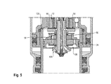
FIG. 5 in a perspective view elements of the spring-damper deviceFIG. 1 ; -
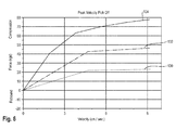
FIG. 6 a plurality of speed-damping force characteristics in a diagram; and -
FIG. 7 Side views of the spring-damper device according to the embodiment.
In
gemäß einem Ausführungsbeispiel dargestellt. Diese dient zur Federung einer Hinterradschwinge eines Fahrrads, insbesondere eines Mountainbikes. Die Vorrichtung 1 hat ein Gehäuse 2 an dem eine Öse 4 ausgebildet ist, mit dem diese an einem Fahrradrahmen eines Fahrrads, insbesondere an einem Rahmenrohr, festklebbar ist. Das Gehäuse 2 wird damit an der Öse 4 derart am Fahrradrahmen befestigt, dass es noch in einer Rahmenebene verschwenkbar ist. Das Gehäuse 2 ist als Zylinderboden eines im Wesentlichen rohrförmigen Luftzylinders 6 ausgebildet. Der Luftzylinder 6 hat ein mit Luft gefülltes Federrohr 8, das an seinem im Gehäuse 2 zuweisenden Endabschnitt ein Außengewinde aufweist über das dies in das Gehäuse 2 in ein entsprechendes Innengewinde dichtend eingeschraubt ist. In dem Federrohr 8 ist ein Gaskolben 10 axial verschiebbar angeordnet, der fest mit einem Dämpferkörper 12 verbunden ist. Der im Wesentlichen hohlzylindrisch ausgebildete Dämpferkörper 12 ist dabei mit seinem zum Gehäuse 2 weisenden Endabschnitt in eine Innenaussparung des Gaskolbens 10 eingeschraubt und somit fest mit diesem verbunden. Der Dämpferkörper 12 durchsetzt einen vom Gehäuse 2 wegweisenden Endabschnitt des Federrohrs 8, der als Führungsbuchse 14 für den Federdämpferkörper 12 ausgebildet ist. Die Führungsbuchse 14 des Federrohrs 8 hat hierbei einen Abstreiferring 16 und einen Dichtring 18. Der Dämpferkörper 12 hat einen vom Gehäuse 2 wegweisenden abgeschlossenen Endabschnitt 20, der eine Öse 22 aufweist, über die Feder-Dämpfervorrichtung 1 mit einer zu dämpfenden Hinterradschwinge des Fahrrads verbunden ist. Die Verbindung erfolgt dabei ebenfalls derart, dass die Feder-Dämpfervorrichtung 1 über die Öse 22 in einer Rahmenebene verschwenkbar ist. Zur Dämpfung einer Federung ist in dem hohlzylindrischen Dämpferkörper ein Dämpferkolben 24 angeordnet, der über eine das Federrohr 8, den Gaskolben 10 und abschnittsweise den Dämpferköper 12 durchsetzende Führungsstange 26 befestigt ist, die wiederum mit ihrem von Dämpferkolben 24 wegweisenden Endabschnitt am Gehäuse 2 beziehungsweise Zylinderboden fixiert ist. Der Dämpferkolben 24 trennt in dem Dämpferkörper 12 einen Zylinderraum 28 von einem von der Führungsstange 26 durchsetzten Ringraum 30. Des Weiteren ist innerhalb des Dämpferkörpers 12 ein in Längsrichtung verschiebbarer Trennkolben 32 angeordnet, der den Zylinderraum 28 von einem Ausgleichsraum 34 trennt. Dieser dient zum Ausgleich des Volumens, wenn die Führungsstange 26 bei einer Längsverschiebung des Dämpferkörpers 12 in Richtung des Gehäuses 2 in diesen eintaucht.In
represented according to an embodiment. This serves to spring a rear swing arm of a bicycle, especially a mountain bike. The device 1 has a
Der Gaskolben 10 ist gleitend auf der Führungsstange 26 über eine Ringdichtung 36 geführt, über die auch der Dämpferkolben 24 gegenüber dem Federrohr 8 abgedichtet ist. Des Weiteren ist der Gaskolben 10 über einen Dichtring 37 und zwei benachbart dazu angeordnete Gleitringe 39 innerhalb des Federrohrs 8 geführt. Der Gaskolben 10 trennt hierbei einen von der Führungsstange 26 durchsetzten Ringraum 52 von einem von dem Dämpferkörper 12 durchsetzten Ringraum 41 des Luftzylinders 6. Eine Funktionsweise des Gaskolbens 10 entspricht hierbei beispielsweise entsprechend, wie eingangs erläutert, Stand der Technik. In dem Dämpferkörper 12 sind im Bereich des Dämpferkolbens 24 mehrere Ventile ausgebildet, um einen Volumenstrom eines Fluids zwischen dem Zylinderraum 28 und dem Ringraum 30 des Dämpferkörpers 12 zu steuern, was unten stehend in den folgenden Figuren näher erläutert ist.The
Die Führungsstange 26 ist rohrförmig ausgebildet und mit ihrem Endabschnitt dichtend in einen Axialvorsprung 38 des Gehäuses 2 eingeschraubt. In die Führungsstange 26 ist dabei ein rohrförmiger Zugstufenventilkörper 40 eingesetzt, mit dem ein Öffnungsquerschnitt eines Ventils im Bereich des Dämpferkolbens 24 steuerbar ist, indem dieser in axialer Richtung relativ zur Führungsstange 26 über eine Rebound- bzw. Zugstufenverstellvorrichtung 42 verstellbar ist. Diese hat einen radial zur Längsachse in das Gehäuse eingesetzten Drehknopf, dessen Endabschnitt mit dem Endabschnitt des Zugstufenventilkörpers 40 zusammenwirkt. In dem rohrförmigen Zugstufenventilkörper 40 ist des Weiteren ein stiftförmiger Kompressionsventilkörper 46 axial verschiebbar eingesetzt, über den ein Öffnungsquerschnitt eines Ventils im Bereich des Dämpferkolbens 24 einstellbar ist (Öffnungsquerschnitt), was ebenfalls unten stehende näher erläutert wird. Zum Einstellen des Öffnungsquerschnitts wird der Ventilkörper 46 in Axialrichtung verschoben, was über einen Hebel 48 erfolgt. Der Hebel 48 ist dabei auf einer axial den Drehknopf 44 durchsetzenden Hebelachse 50 angeordnet, die mit ihrem vom Hebel 48 wegweisenden Endabschnitt mit dem Ventilkörper 46 zusammenwirkt.The
Die Ventile im Bereich des Dämpferkolbens 24 werden anhand der
Der Dämpferkolben 24 ist topfförmig ausgebildet und weist mittig eine zylindrische Aussparung 60 auf. Über diese ist der Dämpferkolben 24 auf ein T-förmiges Ventilstück 62 gesetzt, das mit seinen in Richtung des Gehäuses 2 aus
Die Federscheiben 88 sind von der Federscheibe 82 über mehrere Beilagscheiben, die einen wesentlich geringeren Durchmesser als die Federscheibe 82 aufweisen voneinander beabstandet. In dem Ventilkörper 84 sind des Weiteren im Bereich des Stützbunds 86 Radialaussparungen 92 eingebracht, damit bei geöffneten Ventil 58 Fluid über die Durchgangsöffnung 78 des Führungsrings 76 und die Radialaussparung 92 zum Ringraum 30 strömen kann.The spring washers 88 are spaced apart from the
Über mehrere Beilagscheiben von den Federscheiben 88 beabstandet ist das Ventil 54 auf dem Ventilstück 62 angeordnet. Dieses hat ein topfförmiges Ventilteil 94, das mit seiner konkaven Seite weg vom Dämpferkolben 24 weist. Das Ventilteil 94 ist über eine zylindrische Aussparung auf das Ventilstück 62 gesetzt. Die konkave Seite des Ventilteils 94 ist durch eine Federscheibe 96 verschlossen, deren Durchmesser etwas größer als der Durchmesser der Federscheiben 88 des Ventils 56 ist. Die Federscheibe ist ebenfalls auf dem Ventilstück 62 angeordnet. In den konkaven Innenraum des Ventilteils 94 des Ventils 54 mündet eine Radialbohrung des Ventilstücks 62, die mit einer axialen Durchgangsbohrung 98 des Ventilstücks 62 verbunden ist. Durch die Durchgangsbohrung 98 des Ventilstücks 62 ist der Kompressionsventilkörper 46 hindurchgeführt, der einen geringeren Außendurchmesser als die Durchgangsbohrung 98 hat, womit zwischen der Durchgangsbohrung 98 und dem Kompressionsventilkörper 46 ein Ringkanal ausgebildet ist, der den konkaven Innenraum des Ventilteils 94 fluidisch mit dem Zylinderraum 28 verbindet. Die Federscheibe 96 des Ventils 54 wird somit vom Zylinderraum 28 über den Ringraum des Ventilstücks 62, die radiale Durchgangsbohrung und den konkaven Innenraum des Ventilteils 94 mit einem Druck beaufschlagt. Ab einer bestimmten Druckdifferenz zwischen dem Zylinderraum 28 und dem Ringraum 30 wird die Federscheibe 96 elastisch vom Ventilteil 94 weggebogen, wodurch ein Öffnungsquerschnitt für einen Volumenstrom des Fluids zwischen dem Zylinderraum 28 und dem Ringraum 30 freigegeben ist. Auf der Federscheibe 96 ist eine weitere Beilagscheibe angeordnet, die an einer Ringstirnfläche der Führungsstange 26 anliegt.Spaced over a plurality of washers of the spring washers 88, the
Mit dem Ventilstück 62 ist somit ein Packet aus dem Dämpferkolben 24, dem Führungsring 76, der Federscheibe 82, den Federscheiben 88, den Ventilkörper 84, den Ventilteil 94 und der Federscheibe 96 an der Führungsstange 26 festgelegt. Die Ventile 54, 56 und 58 bilden somit eine äußerst kompakte und einfach aufgebaute Einheit.With the
Der zum Ventil 54 durch das Ventilstück 62 strömende Volumenstrom ist durch den Kompressionsventilkörper 46 einstellbar. Dieser ist hierfür in Axialrichtung über den Hebel 48, siehe
Im Folgenden wird anhand der
Im Folgenden wird unterschieden zwischen einer Einfederung der Feder-Dämpfungseinrichtung 1 in einem langsamen, in einem mittleren und in einem schnellen Geschwindigkeitsbereich. Im langsamen Geschwindigkeitsbereich, d. h. bei leichteren Stößen der Hinterradaufhängung wird der Gaskolben 10 aus der
Im Bereich mittlerer Einfedergeschwindigkeiten steigt die Druckdifferenz zwischen dem Zylinderraum 28 und dem Ringraum 30 weiter an, wobei dann zusätzlich zum Ventil 54 das Ventil 56 öffnet, indem der Ventilkörper 84 axial verschoben wird. In diesem mittleren Geschwindigkeitsbereich sind somit beide Ventile 54 und 56 geöffnet, wodurch ein größerer Volumenstrom zwischen dem Zylinderraum 28 und dem Ringraum 30 strömen kann, wodurch die auf die Feder-Dämpfervorrichtung 1 wirkenden Kräfte vermindert werden.In the range of medium compression speeds, the pressure difference between the
Zur Vermeidung von hohen Belastungen für die Feder-Dämpfervorrichtung 1 im Bereich schneller Geschwindigkeiten, insbesondere bei starken Stößen auf die Hinterradaufhängung, dient das Ventil 58, das zusätzlich zu den Ventilen 54 und 56 bei Übersteigen einer bestimmten Druckdifferenz zwischen dem Zylinderraum 28 und dem Ringraum 30 öffnet. Hierdurch wird ein Öffnungsquerschnitt für einen Volumenstrom zwischen dem Zylinderraum 28 und dem Ringraum 30 weiter vergrößert, wodurch die auf die Feder-Dämpfervorrichtung 1 wirkende Belastung verringert ist.To avoid high loads for the spring-damper device 1 in the range of faster speeds, especially in strong shocks to the rear suspension, the
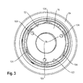
Die
In der
Das Ventil 106 hat eine am Ventilstück 62 festgelegte Federscheibe 110. Diese ist auf einem weg vom Dämpferkolben 24 weisenden Axialvorsprung des Ventilstücks 62 aufgesetzt und mit einer Mutter 112, die auf den Axialvorsprung aufgeschraubt ist, fixiert. Die Federscheibe 110 verschließt im geschlossenen Zustand Schrägbohrungen, die dem Querschenkel 114 des Ventilstücks 62 eingebracht sind und in dessen axialer Durchgangsbohrung 98 münden. Die Durchgangsbohrung 98 des Ventilstücks 62 mündet in einem Ringraum 116 der Führungsstange 26. Der Ringraum wird hierbei von einer Stirnseite des Ventilstücks 62 begrenzt und ist über eine in die Führungsstange 26 eingebrachte Schrägbohrung 118 mit dem Ringraum 30 des Dämpferkörpers 12 fluidisch verbunden. Eine Innenfase des Ventilstücks 62, das zum Ringraum 116 weist dient hierbei als Ventilsitz 120 für den Zugstufenventilkörper 40. Mit diesem kann ein Öffnungsquerschnitt zwischen dem Ringraum 116 und der Durchgangsbohrung 98 über die Verstellvorrichtung 42 aus der
Das Ventil 108 besteht aus den Beilagscheiben 68 der
In der Figur ist ein Geschwindigkeits-Dämpfungskraft-Diagramm dargestellt, in dem eine untere Kurve 130 und eine mittlere Kurve 132 an dem Geschwindigkeits-Dämpfungskraft-Verlauf von herkömmlichen Feder-Dämpfervorrichtungen darstellen, während eine obere Kurve 134 beispielhaft den Geschwindigkeits-Dämpfungskraft-Verlauf der erfindungsgemäßen Feder-Dämpfervorrichtung 1 darstellt. Herkömmliche Feder-Dämpfervorrichtungen weisen in ihrer Kompressionsphase keine drei wirksamen Ventile auf, bei der erfindungsgemäßen Feder-Dämpfervorrichtung 1 vorgesehen ist. Hierdurch ergibt sich der zweiteilige Verlauf der Kurven 130 und 132. Bei der Kurve 130 handelt es sich um einen "weich" eingestellte Feder-Dämpfervorrichtung. Hierbei ist ein in der Kompressionsphase erstes Ventil vorgesehen, das bis zu einer Geschwindigkeit von etwa 5 cm/s einen Volumenstrom eines Fluids einer Dämpfereinrichtung steuert. Bei höheren Geschwindigkeiten ist ein Überdruckventil vorgesehen, das eine derart großen Öffnungsquerschnitt für den Volumenstrom freigibt, dass eine Dämpfungskraft nicht weiter ansteigt. Hierbei ist zwar eine Belastung der Feder-Dämpfervorrichtung gering, allerdings kann dies nachteilig bei starken Stößen einer Hinterradschwinge zu einem Durchschlagen der Feder-Dämpfervorrichtung führen.In the figure, a velocity damping force diagram is shown in which a
Die Kurve 132 zeigt eine Feder-Dämpfervorrichtung aus dem Stand der Technik, die "härter" eingestellt ist. Bis zu einer Geschwindigkeit von etwa 5 cm/s steigt eine Dämpfungskraft in der Kompressionsphase stärker als bei der Kurve 130 an, wodurch ein Durchschlagen der Feder-Dämpfervorrichtung eher nicht mehr möglich ist. Bei höheren Geschwindigkeiten öffnet auch hier ein Überdruckventil, womit Kompressionskräfte kaum mehr ansteigen.
Die Kurve 134 ist im Gegensatz zu den Kurven 130 und 132 dreiteilig aufgebaut. Im ersten Teil, im Geschwindigkeitsbereich zwischen 0 und 2 cm/s wirkt hierbei in der Kompressionsphase das Ventil 54 aus
Die Feder-Dämpfervorrichtung 1 aus
Vergisst ein Fahrer in unwegsamem Gelände den Kompressionsventilkörper 46 zu öffnen, dann dienen die Ventile 56 und 58 aus der
In der
Bei einem Innendurchmesser des Ringraums 52 kann in einem voll eingefederten Zustand das Kompressionsverhältnis (ausgefedertes Volumen /eingefedertes Volumen) mindestens 2,8 betragen. Durch das Hinzufügen eines Spacers 136 kann dieses Verhältnis beispielsweise auf 4,0 angepasst werden, um den verschiedenen Anforderungen der Fahrwerkskinematik gerecht zu werden. Bei herkömmlichen Feder-Dämpfervorrichtungen erfolgt das Einstellen des Kompressionsverhältnisses über verschiedene Luftkammergehäuse (aircan), was vergleichsweise teuer ist. Der Spacer 136 ist in der
- 11
- Feder-DämpfervorrichtungSpring-damper device
- 22
- Gehäuse / ZylinderbodenHousing / cylinder bottom
- 44
- Öseeyelet
- 66
- Luftzylinderair cylinder
- 88th
- Federrohrspring tube
- 1010
- Gaskolbengas piston
- 1212
- Dämpferkörperdamper body
- 1414
- Führungsbuchseguide bush
- 1616
- Abstreiferringwiper ring
- 1818
- Dichtringseal
- 2020
- Endabschnittend
- 2222
- Öseeyelet
- 2424
- Dämpferkolbendamper piston
- 2626
- Führungstangeguide rod
- 2828
- Zylinderraumcylinder space
- 3030
- Ringraumannulus
- 3232
- Trennkolbenseparating piston
- 3434
- Ausgleichsraumcompensation space
- 3636
- Ringdichtungring seal
- 3737
- Dichtringseal
- 3838
- Axialvorsprungaxial projection
- 3939
- Gleitringsliding ring
- 4040
- ZugstufenventilkörperZugstufenventilkörper
- 4141
- Ringraumannulus
- 4242
- Verstellvorrichtungadjustment
- 4444
- Drehknopfknob
- 4646
- KompressionsventilkörperCompression valve body
- 4848
- Hebellever
- 5050
- Hebelachselever axis
- 5252
- Ringraumannulus
- 5454
- VentilValve
- 5656
- VentilValve
- 5858
- VentilValve
- 6060
- Aussparungrecess
- 6262
- Ventilstückvalve piece
- 6464
- Endabschnittend
- 6666
- Endabschnittend
- 6868
- Beilagscheiben / FederscheibenWashers / spring washers
- 7070
- Querschenkeltransverse leg
- 7272
- Kolbenringpiston ring
- 7474
- Stirnseitefront
- 7676
- Führungsringguide ring
- 7878
- DurchgangsöffnungThrough opening
- 8080
- DurchgangsöffnungThrough opening
- 8282
- Federscheibespring washer
- 8484
- Ventilkörpervalve body
- 8686
- Stützbundsupporting collar
- 8888
- Federscheibenspring washers
- 9090
- DurchgangsbohrungThrough Hole
- 9292
- Radialaussparungradial recess
- 9494
- Ventilteilvalve part
- 9696
- Federscheibespring washer
- 9898
- DurchgangsbohrungThrough Hole
- 100100
- Endabschnittend
- 102102
- InnenmantelflächeInner surface area
- 104104
- Längsnutlongitudinal groove
- 106106
- VentilValve
- 108108
- VentilValve
- 110110
- Federscheibespring washer
- 112112
- Muttermother
- 114114
- Schrägbohrungoblique bore
- 116116
- Ringraumannulus
- 118118
- Schrägbohrungoblique bore
- 120120
- Ventilsitzvalve seat
- 122122
- DurchgangsöffnungThrough opening
- 124124
- Radialnutradial groove
- 126126
- Radialnutradial groove
- 128128
- InnenbodenflächeInterior floor area
- 130130
- KurveCurve
- 132132
- KurveCurve
- 134134
- Nockencam
- 136136
- Spacerspacer
Claims (15)
Applications Claiming Priority (1)
| Application Number | Priority Date | Filing Date | Title |
|---|---|---|---|
| DE102011053127A DE102011053127A1 (en) | 2011-08-30 | 2011-08-30 | Spring damper device for a bicycle |
Publications (4)
| Publication Number | Publication Date |
|---|---|
| EP2565491A2 true EP2565491A2 (en) | 2013-03-06 |
| EP2565491A3 EP2565491A3 (en) | 2014-06-11 |
| EP2565491B1 EP2565491B1 (en) | 2018-10-10 |
| EP2565491B8 EP2565491B8 (en) | 2018-12-26 |
Family
ID=46934443
Family Applications (1)
| Application Number | Title | Priority Date | Filing Date |
|---|---|---|---|
| EP12181817.3A Active EP2565491B8 (en) | 2011-08-30 | 2012-08-24 | Spring damper device for a bicycle |
Country Status (3)
| Country | Link |
|---|---|
| US (1) | US9273746B2 (en) |
| EP (1) | EP2565491B8 (en) |
| DE (1) | DE102011053127A1 (en) |
Cited By (2)
| Publication number | Priority date | Publication date | Assignee | Title |
|---|---|---|---|---|
| EP3009708A3 (en) * | 2014-09-01 | 2016-12-21 | WP Performance Systems GmbH | Vibration damper with independently adjustable shock absorption for the traction phase and the pressure phase |
| CN108547902A (en) * | 2018-07-04 | 2018-09-18 | 苏州浪潮智能软件有限公司 | A kind of gas spring of adjustable pressure |
Families Citing this family (17)
| Publication number | Priority date | Publication date | Assignee | Title |
|---|---|---|---|---|
| US9151355B2 (en) * | 2013-04-16 | 2015-10-06 | Racingbros International Incorporated | Co-axial adjustable damping assembly |
| US9156520B2 (en) * | 2013-08-06 | 2015-10-13 | Sram, Llc | Control assembly for a bicycle shock absorber |
| US9573649B2 (en) | 2014-04-03 | 2017-02-21 | Eko Sport, Inc. | Ramp control for a front fork of a bicycle |
| CN104632977B (en) * | 2015-01-30 | 2017-08-15 | 常州市达文电动车辆配件厂 | A kind of air-pressure damping damper of the mechanism of air-pressure damping mechanism and application |
| US10955024B2 (en) * | 2015-06-26 | 2021-03-23 | Fox Factory, Inc. | Dual piston system |
| EP3409973A1 (en) * | 2017-06-01 | 2018-12-05 | Öhlins Racing AB | Electronically controlled valve for a shock absorber |
| IT201700066407A1 (en) * | 2017-06-15 | 2018-12-15 | Formula S A S Di Formula Group S R L & C | ADJUSTABLE SHOCK ABSORBER IN COMPRESSION AND RETURN |
| US11008062B2 (en) | 2017-08-17 | 2021-05-18 | Eko Sport, Inc. | Suspension including coil spring and ambient air cushion |
| IT201800003955A1 (en) * | 2018-03-26 | 2019-09-26 | Formula S A S Di Formula Group S R L & C | PNEUMATIC SPRING |
| DE102018114679B3 (en) * | 2018-06-19 | 2019-05-02 | Ktm Ag | vibration |
| US11040754B2 (en) * | 2019-01-18 | 2021-06-22 | Sram, Llc | Dampers for bicycle suspension components |
| CN110319141A (en) * | 2019-08-13 | 2019-10-11 | 陈国强 | A kind of non-coplanar damping piston gear check in circuit |
| EP3786478A1 (en) * | 2019-09-02 | 2021-03-03 | Öhlins Racing AB | Adjustable bleed valve assembly for shock absorber |
| CN112161015B (en) | 2020-10-28 | 2022-05-06 | 北京京西重工有限公司 | Hydraulic damper assembly and additional piston for a hydraulic damper assembly |
| CN113062945B (en) * | 2021-04-30 | 2022-12-23 | 济南弋泽展特机械有限公司 | Air spring shock absorber length adjusting valve |
| US11801912B2 (en) * | 2021-10-13 | 2023-10-31 | Vince Costa | Motorcycle suspension |
| AU2023204324A1 (en) * | 2022-07-06 | 2024-01-25 | Giant Manufacturing Co., Ltd. | Bicycle shock absorber structure and bicycle |
Citations (1)
| Publication number | Priority date | Publication date | Assignee | Title |
|---|---|---|---|---|
| US6360857B1 (en) | 1999-03-19 | 2002-03-26 | Fox Factory, Inc. | Damping adjuster for shock absorber |
Family Cites Families (19)
| Publication number | Priority date | Publication date | Assignee | Title |
|---|---|---|---|---|
| GB2220726B (en) * | 1988-06-07 | 1992-07-08 | Tokico Ltd | A hydraulic damper of adjustable damping force type |
| DE3925470C2 (en) * | 1988-08-02 | 1996-04-18 | Atsugi Motor Parts Co Ltd | Shock absorbers with a damping valve construction with a variable damping characteristic within a wide range |
| JP2857403B2 (en) * | 1989-02-14 | 1999-02-17 | 株式会社ユニシアジェックス | Variable damping force type hydraulic shock absorber |
| JPH02275128A (en) * | 1989-04-17 | 1990-11-09 | Atsugi Unisia Corp | Variable damping force system for liquid pressure buffer |
| JPH02278026A (en) * | 1989-04-20 | 1990-11-14 | Tokico Ltd | Hydraulic shock absorber |
| NL9300316A (en) * | 1993-02-19 | 1994-09-16 | Koni Bv | One-pipe shock absorber. |
| US5823306A (en) * | 1996-11-12 | 1998-10-20 | Tenneco Automotive Inc. | Stroke dependent damping |
| US6279703B1 (en) * | 2000-05-15 | 2001-08-28 | A-Pro Cycles, Inc. | Shock absorbing adjusting structure |
| US6491146B1 (en) * | 2001-08-21 | 2002-12-10 | Chen-Shing Yi | Damping adjustable shock absorber for a bicycle |
| US7703585B2 (en) * | 2002-06-25 | 2010-04-27 | Fox Factory, Inc. | Integrated and self-contained suspension assembly having an on-the-fly adjustable air spring |
| US7070029B2 (en) * | 2003-09-15 | 2006-07-04 | Tenneco Automotive Operating Company Inc. | Monotube piston valving system with selective bleed |
| US7441640B2 (en) * | 2003-10-08 | 2008-10-28 | Peter Russell | Shock absorber apparatus |
| JP4523485B2 (en) * | 2004-05-25 | 2010-08-11 | 日立オートモティブシステムズ株式会社 | Hydraulic shock absorber |
| US7147207B2 (en) * | 2004-11-04 | 2006-12-12 | Sram Corporation | Actuator apparatus for controlling a valve mechanism of a suspension system |
| US7914031B2 (en) * | 2006-08-07 | 2011-03-29 | Specialized Bicycle Components, Inc. | Bicycle damper |
| US8069964B2 (en) * | 2007-06-21 | 2011-12-06 | Tenneco Automotive Operating Company Inc. | Junction bleed |
| US8869959B2 (en) * | 2008-07-24 | 2014-10-28 | Fox Factory, Incorporated | Vehicle suspension damper |
| US20090267316A1 (en) * | 2008-04-25 | 2009-10-29 | Jose Gonzalez | Bicycle shock assemblies |
| US8622180B2 (en) * | 2010-01-20 | 2014-01-07 | Fox Factory, Inc. | Methods and apparatus for variable damping adjuster |
-
2011
- 2011-08-30 DE DE102011053127A patent/DE102011053127A1/en active Pending
-
2012
- 2012-08-24 EP EP12181817.3A patent/EP2565491B8/en active Active
- 2012-08-30 US US13/599,422 patent/US9273746B2/en active Active
Patent Citations (1)
| Publication number | Priority date | Publication date | Assignee | Title |
|---|---|---|---|---|
| US6360857B1 (en) | 1999-03-19 | 2002-03-26 | Fox Factory, Inc. | Damping adjuster for shock absorber |
Cited By (2)
| Publication number | Priority date | Publication date | Assignee | Title |
|---|---|---|---|---|
| EP3009708A3 (en) * | 2014-09-01 | 2016-12-21 | WP Performance Systems GmbH | Vibration damper with independently adjustable shock absorption for the traction phase and the pressure phase |
| CN108547902A (en) * | 2018-07-04 | 2018-09-18 | 苏州浪潮智能软件有限公司 | A kind of gas spring of adjustable pressure |
Also Published As
| Publication number | Publication date |
|---|---|
| EP2565491B1 (en) | 2018-10-10 |
| EP2565491B8 (en) | 2018-12-26 |
| US20130105260A1 (en) | 2013-05-02 |
| DE102011053127A1 (en) | 2013-02-28 |
| US9273746B2 (en) | 2016-03-01 |
| EP2565491A3 (en) | 2014-06-11 |
Similar Documents
| Publication | Publication Date | Title |
|---|---|---|
| EP2565491B1 (en) | Spring damper device for a bicycle | |
| DE10234906B4 (en) | Adjustment of the compression damping of a shock absorber | |
| EP0715091B1 (en) | Adjustable vibration damper | |
| EP1745222B1 (en) | Air spring | |
| DE10025399C2 (en) | vibration | |
| DE3303293C2 (en) | Hydraulic telescopic shock absorber with adjustable damping for vehicles | |
| DE19964466B4 (en) | Shock absorbers with passive damping influence and vehicle suspension with such shock absorbers | |
| DE112013004595B4 (en) | suspension device | |
| DE212006000103U1 (en) | Damping system for a bicycle suspension | |
| DE112005002609T5 (en) | Shock-dependent damping | |
| WO2008119443A1 (en) | Spring assembly with adjustable spring rate, and spring strut with such a spring assembly | |
| DE102015214343A1 (en) | Vehicle with shock absorber | |
| DE102014111799A1 (en) | A damper assembly for a vehicle suspension system including a fluid damper and multiple chamber gas spring, and methods for controlling preload, spring rate, and ground clearance | |
| DE1505417B1 (en) | Infinitely adjustable shock absorber, especially for motor vehicles | |
| DE112019002773T5 (en) | Suspension device | |
| DE4429562C2 (en) | Hydraulic vibration damper for the sprung front wheel of a bicycle | |
| DE112021003611T5 (en) | SHOCK ABSORBER | |
| EP2977640A2 (en) | Vibration absorber | |
| EP2511564B1 (en) | Device and method for guiding a wheel of a vehicle | |
| DE69725954T2 (en) | Set up and use a shock absorber | |
| EP3009708B1 (en) | Vibration damper with independently adjustable shock absorption for the traction phase and the pressure phase | |
| EP2479097B1 (en) | Telescopic suspension fork with hydraulic end stop | |
| DE102008053092B4 (en) | Bicycle suspension system | |
| DE102017220273B4 (en) | Damping device for a motor vehicle and motor vehicle with damping device | |
| DE3202721A1 (en) | Proportional pressure valve for hydropneumatic vibration dampers, in particular a bottom valve which can be installed in twin-tube dampers |
Legal Events
| Date | Code | Title | Description |
|---|---|---|---|
| PUAI | Public reference made under article 153(3) epc to a published international application that has entered the european phase |
Free format text: ORIGINAL CODE: 0009012 |
|
| AK | Designated contracting states |
Kind code of ref document: A2 Designated state(s): AL AT BE BG CH CY CZ DE DK EE ES FI FR GB GR HR HU IE IS IT LI LT LU LV MC MK MT NL NO PL PT RO RS SE SI SK SM TR |
|
| AX | Request for extension of the european patent |
Extension state: BA ME |
|
| RAP1 | Party data changed (applicant data changed or rights of an application transferred) |
Owner name: B-LABS AG |
|
| PUAL | Search report despatched |
Free format text: ORIGINAL CODE: 0009013 |
|
| AK | Designated contracting states |
Kind code of ref document: A3 Designated state(s): AL AT BE BG CH CY CZ DE DK EE ES FI FR GB GR HR HU IE IS IT LI LT LU LV MC MK MT NL NO PL PT RO RS SE SI SK SM TR |
|
| AX | Request for extension of the european patent |
Extension state: BA ME |
|
| RIC1 | Information provided on ipc code assigned before grant |
Ipc: B62K 25/10 20060101ALI20140502BHEP Ipc: B62K 25/06 20060101ALI20140502BHEP Ipc: F16F 9/348 20060101ALI20140502BHEP Ipc: F16F 9/46 20060101AFI20140502BHEP |
|
| 17P | Request for examination filed |
Effective date: 20141125 |
|
| RBV | Designated contracting states (corrected) |
Designated state(s): AL AT BE BG CH CY CZ DE DK EE ES FI FR GB GR HR HU IE IS IT LI LT LU LV MC MK MT NL NO PL PT RO RS SE SI SK SM TR |
|
| STAA | Information on the status of an ep patent application or granted ep patent |
Free format text: STATUS: EXAMINATION IS IN PROGRESS |
|
| 17Q | First examination report despatched |
Effective date: 20161124 |
|
| GRAP | Despatch of communication of intention to grant a patent |
Free format text: ORIGINAL CODE: EPIDOSNIGR1 |
|
| STAA | Information on the status of an ep patent application or granted ep patent |
Free format text: STATUS: GRANT OF PATENT IS INTENDED |
|
| INTG | Intention to grant announced |
Effective date: 20180320 |
|
| GRAS | Grant fee paid |
Free format text: ORIGINAL CODE: EPIDOSNIGR3 |
|
| RAP1 | Party data changed (applicant data changed or rights of an application transferred) |
Owner name: FOX FACTORY SWITZERLAND GMBH |
|
| GRAA | (expected) grant |
Free format text: ORIGINAL CODE: 0009210 |
|
| STAA | Information on the status of an ep patent application or granted ep patent |
Free format text: STATUS: THE PATENT HAS BEEN GRANTED |
|
| AK | Designated contracting states |
Kind code of ref document: B1 Designated state(s): AL AT BE BG CH CY CZ DE DK EE ES FI FR GB GR HR HU IE IS IT LI LT LU LV MC MK MT NL NO PL PT RO RS SE SI SK SM TR |
|
| REG | Reference to a national code |
Ref country code: GB Ref legal event code: FG4D Free format text: NOT ENGLISH |
|
| REG | Reference to a national code |
Ref country code: CH Ref legal event code: EP Ref country code: AT Ref legal event code: REF Ref document number: 1051621 Country of ref document: AT Kind code of ref document: T Effective date: 20181015 |
|
| REG | Reference to a national code |
Ref country code: IE Ref legal event code: FG4D Free format text: LANGUAGE OF EP DOCUMENT: GERMAN Ref country code: DE Ref legal event code: R096 Ref document number: 502012013575 Country of ref document: DE |
|
| REG | Reference to a national code |
Ref country code: CH Ref legal event code: PK Free format text: BERICHTIGUNGEN |
|
| REG | Reference to a national code |
Ref country code: CH Ref legal event code: PK Free format text: BERICHTIGUNG B8 |
|
| RIN2 | Information on inventor provided after grant (corrected) |
Inventor name: CHEN, MENG TSUNG Inventor name: FELSL, ANDREAS |
|
| REG | Reference to a national code |
Ref country code: NL Ref legal event code: MP Effective date: 20181010 |
|
| REG | Reference to a national code |
Ref country code: LT Ref legal event code: MG4D |
|
| PG25 | Lapsed in a contracting state [announced via postgrant information from national office to epo] |
Ref country code: NL Free format text: LAPSE BECAUSE OF FAILURE TO SUBMIT A TRANSLATION OF THE DESCRIPTION OR TO PAY THE FEE WITHIN THE PRESCRIBED TIME-LIMIT Effective date: 20181010 |
|
| PG25 | Lapsed in a contracting state [announced via postgrant information from national office to epo] |
Ref country code: BG Free format text: LAPSE BECAUSE OF FAILURE TO SUBMIT A TRANSLATION OF THE DESCRIPTION OR TO PAY THE FEE WITHIN THE PRESCRIBED TIME-LIMIT Effective date: 20190110 Ref country code: LT Free format text: LAPSE BECAUSE OF FAILURE TO SUBMIT A TRANSLATION OF THE DESCRIPTION OR TO PAY THE FEE WITHIN THE PRESCRIBED TIME-LIMIT Effective date: 20181010 Ref country code: FI Free format text: LAPSE BECAUSE OF FAILURE TO SUBMIT A TRANSLATION OF THE DESCRIPTION OR TO PAY THE FEE WITHIN THE PRESCRIBED TIME-LIMIT Effective date: 20181010 Ref country code: NO Free format text: LAPSE BECAUSE OF FAILURE TO SUBMIT A TRANSLATION OF THE DESCRIPTION OR TO PAY THE FEE WITHIN THE PRESCRIBED TIME-LIMIT Effective date: 20190110 Ref country code: IS Free format text: LAPSE BECAUSE OF FAILURE TO SUBMIT A TRANSLATION OF THE DESCRIPTION OR TO PAY THE FEE WITHIN THE PRESCRIBED TIME-LIMIT Effective date: 20190210 Ref country code: ES Free format text: LAPSE BECAUSE OF FAILURE TO SUBMIT A TRANSLATION OF THE DESCRIPTION OR TO PAY THE FEE WITHIN THE PRESCRIBED TIME-LIMIT Effective date: 20181010 Ref country code: LV Free format text: LAPSE BECAUSE OF FAILURE TO SUBMIT A TRANSLATION OF THE DESCRIPTION OR TO PAY THE FEE WITHIN THE PRESCRIBED TIME-LIMIT Effective date: 20181010 Ref country code: HR Free format text: LAPSE BECAUSE OF FAILURE TO SUBMIT A TRANSLATION OF THE DESCRIPTION OR TO PAY THE FEE WITHIN THE PRESCRIBED TIME-LIMIT Effective date: 20181010 Ref country code: PL Free format text: LAPSE BECAUSE OF FAILURE TO SUBMIT A TRANSLATION OF THE DESCRIPTION OR TO PAY THE FEE WITHIN THE PRESCRIBED TIME-LIMIT Effective date: 20181010 |
|
| PG25 | Lapsed in a contracting state [announced via postgrant information from national office to epo] |
Ref country code: PT Free format text: LAPSE BECAUSE OF FAILURE TO SUBMIT A TRANSLATION OF THE DESCRIPTION OR TO PAY THE FEE WITHIN THE PRESCRIBED TIME-LIMIT Effective date: 20190210 Ref country code: AL Free format text: LAPSE BECAUSE OF FAILURE TO SUBMIT A TRANSLATION OF THE DESCRIPTION OR TO PAY THE FEE WITHIN THE PRESCRIBED TIME-LIMIT Effective date: 20181010 Ref country code: SE Free format text: LAPSE BECAUSE OF FAILURE TO SUBMIT A TRANSLATION OF THE DESCRIPTION OR TO PAY THE FEE WITHIN THE PRESCRIBED TIME-LIMIT Effective date: 20181010 Ref country code: GR Free format text: LAPSE BECAUSE OF FAILURE TO SUBMIT A TRANSLATION OF THE DESCRIPTION OR TO PAY THE FEE WITHIN THE PRESCRIBED TIME-LIMIT Effective date: 20190111 Ref country code: RS Free format text: LAPSE BECAUSE OF FAILURE TO SUBMIT A TRANSLATION OF THE DESCRIPTION OR TO PAY THE FEE WITHIN THE PRESCRIBED TIME-LIMIT Effective date: 20181010 |
|
| REG | Reference to a national code |
Ref country code: DE Ref legal event code: R097 Ref document number: 502012013575 Country of ref document: DE |
|
| PG25 | Lapsed in a contracting state [announced via postgrant information from national office to epo] |
Ref country code: CZ Free format text: LAPSE BECAUSE OF FAILURE TO SUBMIT A TRANSLATION OF THE DESCRIPTION OR TO PAY THE FEE WITHIN THE PRESCRIBED TIME-LIMIT Effective date: 20181010 Ref country code: DK Free format text: LAPSE BECAUSE OF FAILURE TO SUBMIT A TRANSLATION OF THE DESCRIPTION OR TO PAY THE FEE WITHIN THE PRESCRIBED TIME-LIMIT Effective date: 20181010 Ref country code: IT Free format text: LAPSE BECAUSE OF FAILURE TO SUBMIT A TRANSLATION OF THE DESCRIPTION OR TO PAY THE FEE WITHIN THE PRESCRIBED TIME-LIMIT Effective date: 20181010 |
|
| PLBE | No opposition filed within time limit |
Free format text: ORIGINAL CODE: 0009261 |
|
| STAA | Information on the status of an ep patent application or granted ep patent |
Free format text: STATUS: NO OPPOSITION FILED WITHIN TIME LIMIT |
|
| PG25 | Lapsed in a contracting state [announced via postgrant information from national office to epo] |
Ref country code: SM Free format text: LAPSE BECAUSE OF FAILURE TO SUBMIT A TRANSLATION OF THE DESCRIPTION OR TO PAY THE FEE WITHIN THE PRESCRIBED TIME-LIMIT Effective date: 20181010 Ref country code: EE Free format text: LAPSE BECAUSE OF FAILURE TO SUBMIT A TRANSLATION OF THE DESCRIPTION OR TO PAY THE FEE WITHIN THE PRESCRIBED TIME-LIMIT Effective date: 20181010 Ref country code: SK Free format text: LAPSE BECAUSE OF FAILURE TO SUBMIT A TRANSLATION OF THE DESCRIPTION OR TO PAY THE FEE WITHIN THE PRESCRIBED TIME-LIMIT Effective date: 20181010 Ref country code: RO Free format text: LAPSE BECAUSE OF FAILURE TO SUBMIT A TRANSLATION OF THE DESCRIPTION OR TO PAY THE FEE WITHIN THE PRESCRIBED TIME-LIMIT Effective date: 20181010 |
|
| 26N | No opposition filed |
Effective date: 20190711 |
|
| PG25 | Lapsed in a contracting state [announced via postgrant information from national office to epo] |
Ref country code: SI Free format text: LAPSE BECAUSE OF FAILURE TO SUBMIT A TRANSLATION OF THE DESCRIPTION OR TO PAY THE FEE WITHIN THE PRESCRIBED TIME-LIMIT Effective date: 20181010 |
|
| REG | Reference to a national code |
Ref country code: DE Ref legal event code: R119 Ref document number: 502012013575 Country of ref document: DE |
|
| PG25 | Lapsed in a contracting state [announced via postgrant information from national office to epo] |
Ref country code: TR Free format text: LAPSE BECAUSE OF FAILURE TO SUBMIT A TRANSLATION OF THE DESCRIPTION OR TO PAY THE FEE WITHIN THE PRESCRIBED TIME-LIMIT Effective date: 20181010 |
|
| PG25 | Lapsed in a contracting state [announced via postgrant information from national office to epo] |
Ref country code: LU Free format text: LAPSE BECAUSE OF NON-PAYMENT OF DUE FEES Effective date: 20190824 Ref country code: CH Free format text: LAPSE BECAUSE OF NON-PAYMENT OF DUE FEES Effective date: 20190831 Ref country code: LI Free format text: LAPSE BECAUSE OF NON-PAYMENT OF DUE FEES Effective date: 20190831 Ref country code: MC Free format text: LAPSE BECAUSE OF FAILURE TO SUBMIT A TRANSLATION OF THE DESCRIPTION OR TO PAY THE FEE WITHIN THE PRESCRIBED TIME-LIMIT Effective date: 20181010 |
|
| REG | Reference to a national code |
Ref country code: BE Ref legal event code: MM Effective date: 20190831 |
|
| PG25 | Lapsed in a contracting state [announced via postgrant information from national office to epo] |
Ref country code: DE Free format text: LAPSE BECAUSE OF NON-PAYMENT OF DUE FEES Effective date: 20200303 Ref country code: IE Free format text: LAPSE BECAUSE OF NON-PAYMENT OF DUE FEES Effective date: 20190824 Ref country code: FR Free format text: LAPSE BECAUSE OF NON-PAYMENT OF DUE FEES Effective date: 20190831 |
|
| PG25 | Lapsed in a contracting state [announced via postgrant information from national office to epo] |
Ref country code: BE Free format text: LAPSE BECAUSE OF NON-PAYMENT OF DUE FEES Effective date: 20190831 |
|
| REG | Reference to a national code |
Ref country code: AT Ref legal event code: MM01 Ref document number: 1051621 Country of ref document: AT Kind code of ref document: T Effective date: 20190824 |
|
| PG25 | Lapsed in a contracting state [announced via postgrant information from national office to epo] |
Ref country code: AT Free format text: LAPSE BECAUSE OF NON-PAYMENT OF DUE FEES Effective date: 20190824 |
|
| REG | Reference to a national code |
Ref country code: GB Ref legal event code: 732E Free format text: REGISTERED BETWEEN 20210121 AND 20210127 |
|
| PG25 | Lapsed in a contracting state [announced via postgrant information from national office to epo] |
Ref country code: CY Free format text: LAPSE BECAUSE OF FAILURE TO SUBMIT A TRANSLATION OF THE DESCRIPTION OR TO PAY THE FEE WITHIN THE PRESCRIBED TIME-LIMIT Effective date: 20181010 |
|
| PG25 | Lapsed in a contracting state [announced via postgrant information from national office to epo] |
Ref country code: HU Free format text: LAPSE BECAUSE OF FAILURE TO SUBMIT A TRANSLATION OF THE DESCRIPTION OR TO PAY THE FEE WITHIN THE PRESCRIBED TIME-LIMIT; INVALID AB INITIO Effective date: 20120824 Ref country code: MT Free format text: LAPSE BECAUSE OF FAILURE TO SUBMIT A TRANSLATION OF THE DESCRIPTION OR TO PAY THE FEE WITHIN THE PRESCRIBED TIME-LIMIT Effective date: 20181010 |
|
| PG25 | Lapsed in a contracting state [announced via postgrant information from national office to epo] |
Ref country code: MK Free format text: LAPSE BECAUSE OF FAILURE TO SUBMIT A TRANSLATION OF THE DESCRIPTION OR TO PAY THE FEE WITHIN THE PRESCRIBED TIME-LIMIT Effective date: 20181010 |
|
| PGFP | Annual fee paid to national office [announced via postgrant information from national office to epo] |
Ref country code: GB Payment date: 20230803 Year of fee payment: 12 |