EP2565360A1 - Device for securing a roller on a coiling cylinder - Google Patents
Device for securing a roller on a coiling cylinder Download PDFInfo
- Publication number
- EP2565360A1 EP2565360A1 EP12182133A EP12182133A EP2565360A1 EP 2565360 A1 EP2565360 A1 EP 2565360A1 EP 12182133 A EP12182133 A EP 12182133A EP 12182133 A EP12182133 A EP 12182133A EP 2565360 A1 EP2565360 A1 EP 2565360A1
- Authority
- EP
- European Patent Office
- Prior art keywords
- belt
- shutter
- spring
- roller
- winding
- Prior art date
- Legal status (The legal status is an assumption and is not a legal conclusion. Google has not performed a legal analysis and makes no representation as to the accuracy of the status listed.)
- Granted
Links
Images

Classifications
-
- E—FIXED CONSTRUCTIONS
- E06—DOORS, WINDOWS, SHUTTERS, OR ROLLER BLINDS IN GENERAL; LADDERS
- E06B—FIXED OR MOVABLE CLOSURES FOR OPENINGS IN BUILDINGS, VEHICLES, FENCES OR LIKE ENCLOSURES IN GENERAL, e.g. DOORS, WINDOWS, BLINDS, GATES
- E06B9/00—Screening or protective devices for wall or similar openings, with or without operating or securing mechanisms; Closures of similar construction
- E06B9/02—Shutters, movable grilles, or other safety closing devices, e.g. against burglary
- E06B9/08—Roll-type closures
- E06B9/11—Roller shutters
- E06B9/17—Parts or details of roller shutters, e.g. suspension devices, shutter boxes, wicket doors, ventilation openings
- E06B9/171—Rollers therefor; Fastening roller shutters to rollers
Definitions
- the invention relates to a device for fastening a roller shutter to a winding roller.
- a device for connecting a roller blind with a winding shaft wherein at least one strip-shaped, gutter-like and elastically deformable in a flat shape cross-section exhibiting, consisting of blattfederartigem spring element, on the one hand via a connecting member with the roller blind and on the other hand via a holding shell with the winding shaft is connected, wherein the holding shell, which serves for shaft-side connection, is provided at its passage opening with a radius which allows the stretched spring element shortly after leaving this opening can take its trough-shaped baggy shape and further rotation of the shaft on the tangential position prevents the spring element to the shaft addition, while the spring element deforms during winding over almost the entire length in its flat shape.
- a device for attaching a roller shutter to a winding shaft wherein an arm is formed from a plurality of rigid metal profiles, which is attached on the one hand to the winding shaft and on the other hand serves to fasten the shutter.
- the US 962,879 A describes a device for tensioning a curtain comprising a spring-loaded hook.
- the object of the invention is to provide a device which allows the attachment of a shutter on a winding shaft even with small, accessible only from the outside inspection openings in the roller shutter lintel.
- a fastened to the winding roller belt, spring or link belt is provided with a fixed hook connected to the winding roller fishing hook and attached to the end of the belt, spring or link belt catch bolt for independent opening of the Belt, spring or link belt are provided when winding the shutter due to the tensile load and wherein at the end of the belt, spring or link belt a suspension profile is provided for attaching the shutter.
- This device makes it possible to remove the blinds after removal of the guide rails outside the window through the outlet opening of the lintel box.
- the catch hook system opens automatically with attached load, so that the shutter and the belt, spring or link belts can be completely unwound and the upper attachment of the shutter on the belt, spring or link belts for loosening or securing the shutter is accessible.
- the resistance of the tightly closed shutter must be reliably detected so that the drive roller, especially in electric blinds, comes to a standstill and the blinds can not be pushed up from the outside. This is achieved in that the fishing hook pushes when draining the shutter by the resistance occurring over the catch bolt.
- the winding roller can be mounted easily despite the narrow inspection opening.
- the winding roller can be mounted easily despite the narrow inspection opening.
- winding rolls with deferred axis rings, which increase the roll diameter.
- the thickened by the axle rings winding rollers can be used worse through the narrow inspection openings in the lintel boxes.
- the Belt, spring or link belts replace these axle rings when they are wound as the first layer on the drive roller when the roller shutter is pulled in.
- An advantageous embodiment of the invention is that the belt, spring or link belt extends in the unwound state of the arranged in a lintel winding roller through the outlet opening of the lintel.
- the invention provides that the Aufliticianeprofil is provided with a lateral locking.
- the blinds After releasing the lock the blinds can be removed from the suspension profile.
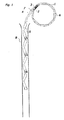
- the belt, spring or link belt 1 is wound around the winding roller 6.
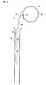
- Fig. 2 the opened catch hook system is shown. Under the tensile load of the shutter 5, the fishing hook 2 releases the catch bolt 3 and the belt, spring or link belt 1 can be completely unwound. When attaching the shutter 5, the winding also takes place according to the figure.
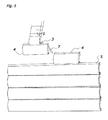
- Fig. 4 shows the device in the position in which the assembly or disassembly of the shutter 5 takes place with removed guide rails 8. By loosening the lateral locking 7, the suspension profile 4 can be pulled out laterally and the shutters 5 are separated and removed from the device.
- Fig. 5 shows the suspension profiles 4, via which the shutter 5 can be connected to the device or separated from it after the detents 7 have been released against displacement.
Abstract
Description
Die Erfindung betrifft eine Vorrichtung zum Befestigen eines Rolladens an einer Wickelwalze.The invention relates to a device for fastening a roller shutter to a winding roller.
Wegen der heute erforderlichen Maßnahmen zur Wärmedämmung sind an den stark isolierten Rolladen-Sturzkästen oft nur noch kleine (oder gar keine) Revisionsöffnungen vorhanden, die zudem nicht an der Rauminnenseite, sondern nur von außen zugänglich sind. Ebenso ist es bei den bisher herkömmlichen, im Mauerwerk integrierten Rolladen-Sturzkästen häufig nicht möglich, Rolläden vor feststehenden Fensterflügeln an der dem Zimmer zugewandten Innenseite zu reinigen, ohne den Revisionsdeckel, der oft verputzt oder übertapeziert wurde, zu öffnen. Schäden an der Zimmerwand-Innenseite sind dann nicht zu vermeiden.Because of the thermal insulation measures required today, often only small (or no) inspection openings are present on the highly insulated roller shutter lintel boxes, which in addition are not accessible on the inside of the room, but only externally. Likewise, it is often not possible in the hitherto conventional, integrated in the masonry roller shutter lintel boxes to clean blinds before fixed window sashes on the inside facing the room, without opening the inspection cover, which was often plastered or over wallpapered. Damage to the inside of the room wall can not be avoided.
Aus der
Aus der
Die
Die Aufgabe der Erfindung besteht darin, eine Vorrichtung zu schaffen, die das Befestigen eines Rolladens an einer Wickelwelle auch bei kleinen, nur von außen zugänglichen Revisionsöffnungen im Rolladen-Sturzkasten ermöglicht.The object of the invention is to provide a device which allows the attachment of a shutter on a winding shaft even with small, accessible only from the outside inspection openings in the roller shutter lintel.
Diese Aufgabe wird erfindungsgemäß dadurch gelöst, daß ein an der Wickelwalze befestigtes Gurt-, Feder- oder Gliederband vorgesehen ist, wobei ein fest mit der Wickelwalze verbundener Fanghaken und ein an dem Ende des Gurt-, Feder- oder Gliederbandes angebrachter Fangbolzen zum selbständigen Öffnen des Gurt-, Feder- oder Gliederbandes beim Aufwickeln des Rolladens aufgrund der Zuglast vorgesehen sind und wobei am Ende des Gurt-, Feder- oder Gliederbandes ein Aufhängeprofil zum Befestigen des Rolladens vorgesehen ist.This object is achieved in that a fastened to the winding roller belt, spring or link belt is provided with a fixed hook connected to the winding roller fishing hook and attached to the end of the belt, spring or link belt catch bolt for independent opening of the Belt, spring or link belt are provided when winding the shutter due to the tensile load and wherein at the end of the belt, spring or link belt a suspension profile is provided for attaching the shutter.
Diese Vorrichtung ermöglicht es, den Rolladen nach Abnahme der Führungsschienen außen vor dem Fenster durch die Austrittsöffnung des Sturzkastens abzunehmen. Das Fanghakensystem öffnet sich selbständig bei anhängender Last, so daß der Rolladen und die Gurt-, Feder- oder Gliederbänder ganz abgewickelt werden können und die obere Befestigung des Rolladens an den Gurt-, Feder- oder Gliederbändern zum Lösen oder Befestigen des Rolladens zugänglich wird. Bei fertig montiertem Rolladen muß hingegen der Widerstand des fest geschlossenen Rolladens zuverlässig erkannt werden, damit die Antriebswalze, insbesondere bei elektrischen Rolläden, zum Stillstand kommt und der Rolladen auch nicht von außen hochgeschoben werden kann. Dies wird dadurch erreicht, daß sich der Fanghaken beim Ablassen des Rolladens durch den auftretenden Widerstand über den Fangbolzen schiebt.This device makes it possible to remove the blinds after removal of the guide rails outside the window through the outlet opening of the lintel box. The catch hook system opens automatically with attached load, so that the shutter and the belt, spring or link belts can be completely unwound and the upper attachment of the shutter on the belt, spring or link belts for loosening or securing the shutter is accessible. When fully assembled blinds, however, the resistance of the tightly closed shutter must be reliably detected so that the drive roller, especially in electric blinds, comes to a standstill and the blinds can not be pushed up from the outside. This is achieved in that the fishing hook pushes when draining the shutter by the resistance occurring over the catch bolt.
Vorteilhaft ist bei der Erfindung auch, daß die Wickelwalze trotz enger Revisionsöffnung leichter montiert werden kann. Um optimale Ballendurchmesser des Rolladens zu erreichen, benutzt man bisher Wickelwalzen mit aufgeschobenen Achsenringen, die den Walzendurchmesser erhöhen. Die durch die Achsenringe verdickten Wickelwalzen können schlechter durch die engen Revisionsöffnungen in die Sturzkästen eingesetzt werden. Die Gurt-, Feder- oder Gliederbänder ersetzen diese Achsenringe, wenn sie als erste Lage auf der Antriebswalze beim Einziehen des Rolladens gewickelt werden.It is also advantageous in the invention that the winding roller can be mounted easily despite the narrow inspection opening. In order to achieve optimum bale diameter of the curtain, so far used winding rolls with deferred axis rings, which increase the roll diameter. The thickened by the axle rings winding rollers can be used worse through the narrow inspection openings in the lintel boxes. The Belt, spring or link belts replace these axle rings when they are wound as the first layer on the drive roller when the roller shutter is pulled in.
Eine vorteilhafte Ausgestaltung der Erfindung besteht darin, daß sich das Gurt-, Feder- oder Gliederband im abgewickelten Zustand von der in einem Sturzkasten angeordneten Wickelwalze durch die Austrittsöffnung des Sturzkastens hindurch erstreckt.An advantageous embodiment of the invention is that the belt, spring or link belt extends in the unwound state of the arranged in a lintel winding roller through the outlet opening of the lintel.
Dies ermöglicht es, den Rolladen außerhalb des Sturzkastens mit dem Gurt-, Feder- oder Gliederband zu verbinden und ihn dann in den Sturzkasten einzuführen.This makes it possible to connect the shutter outside the lintel box with the belt, spring or link belt and then introduce it into the lintel.
Weiterhin ist erfindungsgemäß vorgesehen, daß das Aufliängeprofil mit einer seitlichen Arretierung versehen ist.Furthermore, the invention provides that the Aufliängeprofil is provided with a lateral locking.
Nach Lösen der Arretierung kann der Rolladen von dem Aufhängeprofil entfernt werden.After releasing the lock the blinds can be removed from the suspension profile.
Nachfolgend wird ein Ausführungsbeispiel der Erfindung anhand von Zeichnungen erläutert.Hereinafter, an embodiment of the invention will be explained with reference to drawings.
Es zeigen
- Fig. 1
- die Funktion der Vorrichtung beim Auf- oder Abwickeln des Rolladens,
- Fig. 2
- das geöffnete Fangsystem beim Abwickeln zur Demontage des Rolladens,
- Fig. 3
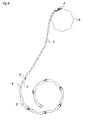
- den Zustand der Vorrichtung bei fest geschlossenem Rolladen,
- Fig. 4
- die Vorrichtung bei abgewickeltem Rolladen,
- Fig. 5
- die Aufhängeprofile.
- Fig. 1
- the function of the device when winding or unwinding the shutter,
- Fig. 2
- the opened catching system when unwinding to disassemble the shutter,
- Fig. 3
- the state of the device with firmly closed shutters,
- Fig. 4
- the device with unwound shutters,
- Fig. 5
- the suspension profiles.
Wie aus
In
Aus
Claims (3)
Applications Claiming Priority (1)
| Application Number | Priority Date | Filing Date | Title |
|---|---|---|---|
| DE201120105244 DE202011105244U1 (en) | 2011-08-29 | 2011-08-29 | Fastening for the installation and maintenance of roller shutters with narrow inspection openings on poorly accessible lintel boxes |
Publications (2)
| Publication Number | Publication Date |
|---|---|
| EP2565360A1 true EP2565360A1 (en) | 2013-03-06 |
| EP2565360B1 EP2565360B1 (en) | 2015-03-18 |
Family
ID=45373049
Family Applications (1)
| Application Number | Title | Priority Date | Filing Date |
|---|---|---|---|
| EP20120182133 Not-in-force EP2565360B1 (en) | 2011-08-29 | 2012-08-29 | Device for securing a roller on a coiling cylinder |
Country Status (4)
| Country | Link |
|---|---|
| EP (1) | EP2565360B1 (en) |
| DE (1) | DE202011105244U1 (en) |
| ES (1) | ES2536908T3 (en) |
| PT (1) | PT2565360E (en) |
Families Citing this family (2)
| Publication number | Priority date | Publication date | Assignee | Title |
|---|---|---|---|---|
| DE102012019435B4 (en) * | 2012-10-04 | 2016-05-04 | Roma Kg | Roller shutter and tank connection module for it |
| DE102012111550A1 (en) * | 2012-11-28 | 2014-05-28 | Lakal Gmbh | shutters system |
Citations (5)
| Publication number | Priority date | Publication date | Assignee | Title |
|---|---|---|---|---|
| US962879A (en) | 1910-04-04 | 1910-06-28 | Lorenzo C Bailey | Curtain-fastener. |
| FR2753742A1 (en) * | 1996-09-20 | 1998-03-27 | Cavaioli Jean Marc | Rapid anchoring system for rapid fixing of roller shutter onto buildings etc. |
| FR2778692A1 (en) | 1998-05-12 | 1999-11-19 | Daniel Bracq | Coupling system for roller shutter and shaft |
| DE202008011566U1 (en) | 2008-08-29 | 2008-10-30 | Klenk, Gottlieb | Device for connecting a roller blind to a winding shaft |
| EP2287435A2 (en) * | 2009-08-18 | 2011-02-23 | Gerhard Geiger GmbH & Co. | Attachment device for connecting a hanging with a winding shaft powered by an electric motor |
-
2011
- 2011-08-29 DE DE201120105244 patent/DE202011105244U1/en not_active Expired - Lifetime
-
2012
- 2012-08-29 PT PT121821334T patent/PT2565360E/en unknown
- 2012-08-29 EP EP20120182133 patent/EP2565360B1/en not_active Not-in-force
- 2012-08-29 ES ES12182133.4T patent/ES2536908T3/en active Active
Patent Citations (5)
| Publication number | Priority date | Publication date | Assignee | Title |
|---|---|---|---|---|
| US962879A (en) | 1910-04-04 | 1910-06-28 | Lorenzo C Bailey | Curtain-fastener. |
| FR2753742A1 (en) * | 1996-09-20 | 1998-03-27 | Cavaioli Jean Marc | Rapid anchoring system for rapid fixing of roller shutter onto buildings etc. |
| FR2778692A1 (en) | 1998-05-12 | 1999-11-19 | Daniel Bracq | Coupling system for roller shutter and shaft |
| DE202008011566U1 (en) | 2008-08-29 | 2008-10-30 | Klenk, Gottlieb | Device for connecting a roller blind to a winding shaft |
| EP2287435A2 (en) * | 2009-08-18 | 2011-02-23 | Gerhard Geiger GmbH & Co. | Attachment device for connecting a hanging with a winding shaft powered by an electric motor |
Also Published As
| Publication number | Publication date |
|---|---|
| ES2536908T3 (en) | 2015-05-29 |
| DE202011105244U1 (en) | 2011-11-21 |
| PT2565360E (en) | 2015-06-08 |
| EP2565360B1 (en) | 2015-03-18 |
Similar Documents
| Publication | Publication Date | Title |
|---|---|---|
| EP2452034B1 (en) | Winding device for covering wall openings or windows | |
| EP2993298B1 (en) | Actuating device, in particular for a darkening device, for actuation with a thread element | |
| EP2565360B1 (en) | Device for securing a roller on a coiling cylinder | |
| EP2500507B1 (en) | holder for upper box | |
| DE202011001804U1 (en) | Device with a lower, roll-up roller shutter for building window openings | |
| EP0441330B1 (en) | Roller shutter with heat insulated and/or armoured flexible door element | |
| EP2738341B1 (en) | Roller shutter system | |
| EP1908915B1 (en) | Assembly method for a rolling gate | |
| EP3573503B1 (en) | Winding device for roller blinds | |
| DE202012100033U1 (en) | Top mounted shutters | |
| EP3392443B1 (en) | Roller shutter mounting kit for a roof window, roof window and roller shutter mounted with such a kit and method for assembling a roller shutter mounting kit on a roof window | |
| DE10031275C1 (en) | Flexible belt, for hanging up armored roller shutter, has stabilizing extensions either side of holding tongue which is bent out or off-set parallel to plane of belt | |
| DE102015000170A1 (en) | External Blinds | |
| DE102015102015B3 (en) | Roller shutter for a insulated rolling room of a roller shutter box | |
| DE102012002788A1 (en) | Device for e.g. opening rolling gate of building, has hook element arranged on side of L-shaped bar such that limbs of hook element and L-shaped bar are interlocked into one another during reduction of width of casing due to wind load | |
| DE102020127200B3 (en) | Roller shutters for closing and / or darkening a building opening and a method for opening a building opening | |
| DE102009013325A1 (en) | Roller blind system for opening e.g. window, of building, has loop arranged around winding and deflecting shafts, where loop is guided by covering element such that covering element is lifted, wound and unwound by loop | |
| AT522526B1 (en) | Protective roller blind | |
| EP1840319A2 (en) | Coiling device of a roller blind | |
| EP1577485A1 (en) | Roller shutter | |
| DE10126813C2 (en) | Roman blind with a single pull cord | |
| DE102010001106A1 (en) | Holder for a mounting rail of a shading system and arrangement of a mounting rail and a holder | |
| DE102015000173A1 (en) | External Blinds | |
| DE2835959C3 (en) | Insect protection device for windows, doors or the like. | |
| DE202015000206U1 (en) | Securing means for roller shutters and roller shutters with such a securing means |
Legal Events
| Date | Code | Title | Description |
|---|---|---|---|
| PUAI | Public reference made under article 153(3) epc to a published international application that has entered the european phase |
Free format text: ORIGINAL CODE: 0009012 |
|
| AK | Designated contracting states |
Kind code of ref document: A1 Designated state(s): AL AT BE BG CH CY CZ DE DK EE ES FI FR GB GR HR HU IE IS IT LI LT LU LV MC MK MT NL NO PL PT RO RS SE SI SK SM TR |
|
| AX | Request for extension of the european patent |
Extension state: BA ME |
|
| 17P | Request for examination filed |
Effective date: 20130826 |
|
| RBV | Designated contracting states (corrected) |
Designated state(s): AL AT BE BG CH CY CZ DE DK EE ES FI FR GB GR HR HU IE IS IT LI LT LU LV MC MK MT NL NO PL PT RO RS SE SI SK SM TR |
|
| GRAP | Despatch of communication of intention to grant a patent |
Free format text: ORIGINAL CODE: EPIDOSNIGR1 |
|
| INTG | Intention to grant announced |
Effective date: 20141016 |
|
| GRAS | Grant fee paid |
Free format text: ORIGINAL CODE: EPIDOSNIGR3 |
|
| GRAA | (expected) grant |
Free format text: ORIGINAL CODE: 0009210 |
|
| AK | Designated contracting states |
Kind code of ref document: B1 Designated state(s): AL AT BE BG CH CY CZ DE DK EE ES FI FR GB GR HR HU IE IS IT LI LT LU LV MC MK MT NL NO PL PT RO RS SE SI SK SM TR |
|
| REG | Reference to a national code |
Ref country code: GB Ref legal event code: FG4D Free format text: NOT ENGLISH |
|
| REG | Reference to a national code |
Ref country code: CH Ref legal event code: EP |
|
| REG | Reference to a national code |
Ref country code: IE Ref legal event code: FG4D Free format text: LANGUAGE OF EP DOCUMENT: GERMAN |
|
| REG | Reference to a national code |
Ref country code: AT Ref legal event code: REF Ref document number: 716712 Country of ref document: AT Kind code of ref document: T Effective date: 20150415 |
|
| REG | Reference to a national code |
Ref country code: DE Ref legal event code: R096 Ref document number: 502012002552 Country of ref document: DE Effective date: 20150430 |
|
| REG | Reference to a national code |
Ref country code: ES Ref legal event code: FG2A Ref document number: 2536908 Country of ref document: ES Kind code of ref document: T3 Effective date: 20150529 |
|
| REG | Reference to a national code |
Ref country code: PT Ref legal event code: SC4A Free format text: AVAILABILITY OF NATIONAL TRANSLATION Effective date: 20150513 |
|
| REG | Reference to a national code |
Ref country code: NL Ref legal event code: T3 |
|
| PG25 | Lapsed in a contracting state [announced via postgrant information from national office to epo] |
Ref country code: SE Free format text: LAPSE BECAUSE OF FAILURE TO SUBMIT A TRANSLATION OF THE DESCRIPTION OR TO PAY THE FEE WITHIN THE PRESCRIBED TIME-LIMIT Effective date: 20150318 Ref country code: LT Free format text: LAPSE BECAUSE OF FAILURE TO SUBMIT A TRANSLATION OF THE DESCRIPTION OR TO PAY THE FEE WITHIN THE PRESCRIBED TIME-LIMIT Effective date: 20150318 Ref country code: HR Free format text: LAPSE BECAUSE OF FAILURE TO SUBMIT A TRANSLATION OF THE DESCRIPTION OR TO PAY THE FEE WITHIN THE PRESCRIBED TIME-LIMIT Effective date: 20150318 Ref country code: NO Free format text: LAPSE BECAUSE OF FAILURE TO SUBMIT A TRANSLATION OF THE DESCRIPTION OR TO PAY THE FEE WITHIN THE PRESCRIBED TIME-LIMIT Effective date: 20150618 Ref country code: FI Free format text: LAPSE BECAUSE OF FAILURE TO SUBMIT A TRANSLATION OF THE DESCRIPTION OR TO PAY THE FEE WITHIN THE PRESCRIBED TIME-LIMIT Effective date: 20150318 |
|
| REG | Reference to a national code |
Ref country code: LT Ref legal event code: MG4D |
|
| PG25 | Lapsed in a contracting state [announced via postgrant information from national office to epo] |
Ref country code: GR Free format text: LAPSE BECAUSE OF FAILURE TO SUBMIT A TRANSLATION OF THE DESCRIPTION OR TO PAY THE FEE WITHIN THE PRESCRIBED TIME-LIMIT Effective date: 20150619 Ref country code: RS Free format text: LAPSE BECAUSE OF FAILURE TO SUBMIT A TRANSLATION OF THE DESCRIPTION OR TO PAY THE FEE WITHIN THE PRESCRIBED TIME-LIMIT Effective date: 20150318 Ref country code: LV Free format text: LAPSE BECAUSE OF FAILURE TO SUBMIT A TRANSLATION OF THE DESCRIPTION OR TO PAY THE FEE WITHIN THE PRESCRIBED TIME-LIMIT Effective date: 20150318 |
|
| PG25 | Lapsed in a contracting state [announced via postgrant information from national office to epo] |
Ref country code: RO Free format text: LAPSE BECAUSE OF FAILURE TO SUBMIT A TRANSLATION OF THE DESCRIPTION OR TO PAY THE FEE WITHIN THE PRESCRIBED TIME-LIMIT Effective date: 20150318 Ref country code: EE Free format text: LAPSE BECAUSE OF FAILURE TO SUBMIT A TRANSLATION OF THE DESCRIPTION OR TO PAY THE FEE WITHIN THE PRESCRIBED TIME-LIMIT Effective date: 20150318 Ref country code: CZ Free format text: LAPSE BECAUSE OF FAILURE TO SUBMIT A TRANSLATION OF THE DESCRIPTION OR TO PAY THE FEE WITHIN THE PRESCRIBED TIME-LIMIT Effective date: 20150318 Ref country code: SK Free format text: LAPSE BECAUSE OF FAILURE TO SUBMIT A TRANSLATION OF THE DESCRIPTION OR TO PAY THE FEE WITHIN THE PRESCRIBED TIME-LIMIT Effective date: 20150318 |
|
| PG25 | Lapsed in a contracting state [announced via postgrant information from national office to epo] |
Ref country code: IS Free format text: LAPSE BECAUSE OF FAILURE TO SUBMIT A TRANSLATION OF THE DESCRIPTION OR TO PAY THE FEE WITHIN THE PRESCRIBED TIME-LIMIT Effective date: 20150718 Ref country code: PL Free format text: LAPSE BECAUSE OF FAILURE TO SUBMIT A TRANSLATION OF THE DESCRIPTION OR TO PAY THE FEE WITHIN THE PRESCRIBED TIME-LIMIT Effective date: 20150318 |
|
| REG | Reference to a national code |
Ref country code: DE Ref legal event code: R097 Ref document number: 502012002552 Country of ref document: DE |
|
| PLBE | No opposition filed within time limit |
Free format text: ORIGINAL CODE: 0009261 |
|
| STAA | Information on the status of an ep patent application or granted ep patent |
Free format text: STATUS: NO OPPOSITION FILED WITHIN TIME LIMIT |
|
| PG25 | Lapsed in a contracting state [announced via postgrant information from national office to epo] |
Ref country code: DK Free format text: LAPSE BECAUSE OF FAILURE TO SUBMIT A TRANSLATION OF THE DESCRIPTION OR TO PAY THE FEE WITHIN THE PRESCRIBED TIME-LIMIT Effective date: 20150318 |
|
| 26N | No opposition filed |
Effective date: 20151221 |
|
| PG25 | Lapsed in a contracting state [announced via postgrant information from national office to epo] |
Ref country code: SI Free format text: LAPSE BECAUSE OF FAILURE TO SUBMIT A TRANSLATION OF THE DESCRIPTION OR TO PAY THE FEE WITHIN THE PRESCRIBED TIME-LIMIT Effective date: 20150318 |
|
| PG25 | Lapsed in a contracting state [announced via postgrant information from national office to epo] |
Ref country code: MC Free format text: LAPSE BECAUSE OF FAILURE TO SUBMIT A TRANSLATION OF THE DESCRIPTION OR TO PAY THE FEE WITHIN THE PRESCRIBED TIME-LIMIT Effective date: 20150318 |
|
| REG | Reference to a national code |
Ref country code: IE Ref legal event code: MM4A |
|
| PG25 | Lapsed in a contracting state [announced via postgrant information from national office to epo] |
Ref country code: IE Free format text: LAPSE BECAUSE OF NON-PAYMENT OF DUE FEES Effective date: 20150829 |
|
| REG | Reference to a national code |
Ref country code: FR Ref legal event code: PLFP Year of fee payment: 5 |
|
| PG25 | Lapsed in a contracting state [announced via postgrant information from national office to epo] |
Ref country code: MT Free format text: LAPSE BECAUSE OF FAILURE TO SUBMIT A TRANSLATION OF THE DESCRIPTION OR TO PAY THE FEE WITHIN THE PRESCRIBED TIME-LIMIT Effective date: 20150318 |
|
| GBPC | Gb: european patent ceased through non-payment of renewal fee |
Effective date: 20160829 |
|
| PG25 | Lapsed in a contracting state [announced via postgrant information from national office to epo] |
Ref country code: SM Free format text: LAPSE BECAUSE OF FAILURE TO SUBMIT A TRANSLATION OF THE DESCRIPTION OR TO PAY THE FEE WITHIN THE PRESCRIBED TIME-LIMIT Effective date: 20150318 Ref country code: BG Free format text: LAPSE BECAUSE OF FAILURE TO SUBMIT A TRANSLATION OF THE DESCRIPTION OR TO PAY THE FEE WITHIN THE PRESCRIBED TIME-LIMIT Effective date: 20150318 Ref country code: HU Free format text: LAPSE BECAUSE OF FAILURE TO SUBMIT A TRANSLATION OF THE DESCRIPTION OR TO PAY THE FEE WITHIN THE PRESCRIBED TIME-LIMIT; INVALID AB INITIO Effective date: 20120829 |
|
| PG25 | Lapsed in a contracting state [announced via postgrant information from national office to epo] |
Ref country code: CY Free format text: LAPSE BECAUSE OF FAILURE TO SUBMIT A TRANSLATION OF THE DESCRIPTION OR TO PAY THE FEE WITHIN THE PRESCRIBED TIME-LIMIT Effective date: 20150318 |
|
| PG25 | Lapsed in a contracting state [announced via postgrant information from national office to epo] |
Ref country code: GB Free format text: LAPSE BECAUSE OF NON-PAYMENT OF DUE FEES Effective date: 20160829 |
|
| REG | Reference to a national code |
Ref country code: FR Ref legal event code: PLFP Year of fee payment: 6 |
|
| PG25 | Lapsed in a contracting state [announced via postgrant information from national office to epo] |
Ref country code: TR Free format text: LAPSE BECAUSE OF FAILURE TO SUBMIT A TRANSLATION OF THE DESCRIPTION OR TO PAY THE FEE WITHIN THE PRESCRIBED TIME-LIMIT Effective date: 20150318 |
|
| PG25 | Lapsed in a contracting state [announced via postgrant information from national office to epo] |
Ref country code: MK Free format text: LAPSE BECAUSE OF FAILURE TO SUBMIT A TRANSLATION OF THE DESCRIPTION OR TO PAY THE FEE WITHIN THE PRESCRIBED TIME-LIMIT Effective date: 20150318 |
|
| REG | Reference to a national code |
Ref country code: FR Ref legal event code: PLFP Year of fee payment: 7 |
|
| PGFP | Annual fee paid to national office [announced via postgrant information from national office to epo] |
Ref country code: LU Payment date: 20180822 Year of fee payment: 7 |
|
| PG25 | Lapsed in a contracting state [announced via postgrant information from national office to epo] |
Ref country code: AL Free format text: LAPSE BECAUSE OF FAILURE TO SUBMIT A TRANSLATION OF THE DESCRIPTION OR TO PAY THE FEE WITHIN THE PRESCRIBED TIME-LIMIT Effective date: 20150318 |
|
| PGFP | Annual fee paid to national office [announced via postgrant information from national office to epo] |
Ref country code: IT Payment date: 20180823 Year of fee payment: 7 Ref country code: ES Payment date: 20180921 Year of fee payment: 7 Ref country code: NL Payment date: 20180822 Year of fee payment: 7 Ref country code: DE Payment date: 20180828 Year of fee payment: 7 Ref country code: FR Payment date: 20180817 Year of fee payment: 7 |
|
| PGFP | Annual fee paid to national office [announced via postgrant information from national office to epo] |
Ref country code: CH Payment date: 20180827 Year of fee payment: 7 Ref country code: BE Payment date: 20180822 Year of fee payment: 7 Ref country code: AT Payment date: 20180821 Year of fee payment: 7 |
|
| PGFP | Annual fee paid to national office [announced via postgrant information from national office to epo] |
Ref country code: PT Payment date: 20180821 Year of fee payment: 7 |
|
| REG | Reference to a national code |
Ref country code: DE Ref legal event code: R119 Ref document number: 502012002552 Country of ref document: DE |
|
| REG | Reference to a national code |
Ref country code: NL Ref legal event code: MM Effective date: 20190901 |
|
| REG | Reference to a national code |
Ref country code: AT Ref legal event code: MM01 Ref document number: 716712 Country of ref document: AT Kind code of ref document: T Effective date: 20190829 |
|
| PG25 | Lapsed in a contracting state [announced via postgrant information from national office to epo] |
Ref country code: AT Free format text: LAPSE BECAUSE OF NON-PAYMENT OF DUE FEES Effective date: 20190829 Ref country code: PT Free format text: LAPSE BECAUSE OF NON-PAYMENT OF DUE FEES Effective date: 20200302 |
|
| PG25 | Lapsed in a contracting state [announced via postgrant information from national office to epo] |
Ref country code: LI Free format text: LAPSE BECAUSE OF NON-PAYMENT OF DUE FEES Effective date: 20190831 Ref country code: LU Free format text: LAPSE BECAUSE OF NON-PAYMENT OF DUE FEES Effective date: 20190829 Ref country code: CH Free format text: LAPSE BECAUSE OF NON-PAYMENT OF DUE FEES Effective date: 20190831 |
|
| REG | Reference to a national code |
Ref country code: BE Ref legal event code: MM Effective date: 20190831 |
|
| PG25 | Lapsed in a contracting state [announced via postgrant information from national office to epo] |
Ref country code: DE Free format text: LAPSE BECAUSE OF NON-PAYMENT OF DUE FEES Effective date: 20200303 Ref country code: FR Free format text: LAPSE BECAUSE OF NON-PAYMENT OF DUE FEES Effective date: 20190831 Ref country code: NL Free format text: LAPSE BECAUSE OF NON-PAYMENT OF DUE FEES Effective date: 20190901 |
|
| PG25 | Lapsed in a contracting state [announced via postgrant information from national office to epo] |
Ref country code: IT Free format text: LAPSE BECAUSE OF NON-PAYMENT OF DUE FEES Effective date: 20190829 Ref country code: BE Free format text: LAPSE BECAUSE OF NON-PAYMENT OF DUE FEES Effective date: 20190831 |
|
| REG | Reference to a national code |
Ref country code: ES Ref legal event code: FD2A Effective date: 20210107 |
|
| PG25 | Lapsed in a contracting state [announced via postgrant information from national office to epo] |
Ref country code: ES Free format text: LAPSE BECAUSE OF NON-PAYMENT OF DUE FEES Effective date: 20190830 |