EP2564983A2 - Schärfer - Google Patents
Schärfer Download PDFInfo
- Publication number
- EP2564983A2 EP2564983A2 EP12182581A EP12182581A EP2564983A2 EP 2564983 A2 EP2564983 A2 EP 2564983A2 EP 12182581 A EP12182581 A EP 12182581A EP 12182581 A EP12182581 A EP 12182581A EP 2564983 A2 EP2564983 A2 EP 2564983A2
- Authority
- EP
- European Patent Office
- Prior art keywords
- sharpener
- frame part
- guide groove
- body part
- compression spring
- Prior art date
- Legal status (The legal status is an assumption and is not a legal conclusion. Google has not performed a legal analysis and makes no representation as to the accuracy of the status listed.)
- Granted
Links
Images

Classifications
-
- B—PERFORMING OPERATIONS; TRANSPORTING
- B24—GRINDING; POLISHING
- B24B—MACHINES, DEVICES, OR PROCESSES FOR GRINDING OR POLISHING; DRESSING OR CONDITIONING OF ABRADING SURFACES; FEEDING OF GRINDING, POLISHING, OR LAPPING AGENTS
- B24B3/00—Sharpening cutting edges, e.g. of tools; Accessories therefor, e.g. for holding the tools
- B24B3/36—Sharpening cutting edges, e.g. of tools; Accessories therefor, e.g. for holding the tools of cutting blades
- B24B3/54—Sharpening cutting edges, e.g. of tools; Accessories therefor, e.g. for holding the tools of cutting blades of hand or table knives
-
- B—PERFORMING OPERATIONS; TRANSPORTING
- B24—GRINDING; POLISHING
- B24D—TOOLS FOR GRINDING, BUFFING OR SHARPENING
- B24D15/00—Hand tools or other devices for non-rotary grinding, polishing, or stropping
- B24D15/06—Hand tools or other devices for non-rotary grinding, polishing, or stropping specially designed for sharpening cutting edges
- B24D15/08—Hand tools or other devices for non-rotary grinding, polishing, or stropping specially designed for sharpening cutting edges of knives; of razors
- B24D15/081—Hand tools or other devices for non-rotary grinding, polishing, or stropping specially designed for sharpening cutting edges of knives; of razors with sharpening elements in interengaging or in mutual contact
- B24D15/082—Hand tools or other devices for non-rotary grinding, polishing, or stropping specially designed for sharpening cutting edges of knives; of razors with sharpening elements in interengaging or in mutual contact the elements being rotatable
Definitions
- the invention relates to a sharpener for sharpening a cutting tool, such as a knife, the sharpener comprising a body part, a rotatable sharpening roll supported by the body part, and a first guide groove above the sharpening roll for receiving a blade of a first tool and for guiding it in relation to the sharpening roll.
- Such a sharpener for sharpening household knives is commonly known.
- the sharpening roll When the blade of a knife to be sharpened is placed into the groove of the sharpening roll and the blade is moved a number of times back and forth in relation to the body part of the sharpener, the sharpening roll, at the same time as it rotates, sharpens the blade of the tool.
- the blade of the tool to be sharpened must be at a specific angle to the groove of the sharpening roll.
- the sharpener comprises a wedge-like guide groove above the sharpening roll for receiving the blade and guiding it to the correct angle.
- the guide groove keeps the blade in the correct position when the blade is moved back and forth on the sharpening roll. If the guide groove is made too wide, i.e., there is a gap that is too large between the guide groove and the blade side, it is possible that the blade to be sharpened sets inclined at a wrong angle in relation to the sharpening roll, in which case the blade to be sharpened becomes lopsided. This means that for narrow blades, a narrow guide groove must be provided.
- a sharpener designed for narrow blades must have a guide groove that is narrow enough so that a wider blade, such as an axe blade, becomes tightly wedged to the walls of the guide groove and the portion of the blade to be sharpened does not reach the groove of the sharpening roll.
- sharpening is naturally impossible.
- sharpeners with a wider guide groove for axes and wide blades than in sharpeners designed for knives.
- Such sharpeners for axes cannot be used without problems - for the above reasons - for sharpening knives.
- a sharpener of the invention characterized in that the sharpener comprises a second guide groove, which is wider than the first guide groove, to be arranged above the sharpening roll to allow a blade of a second tool to be received and guided in relation to the sharpening roll.
- the invention is based on an idea of providing one and the same sharpener with guide grooves of different width, which grooves can be positioned at a desired location above one and the same sharpening roll for guiding a blade in relation to the appropriate sharpening roll. This allows the one and the same sharpening roll to be utilized for sharpening both narrow blades and wide blades.
- the narrower one of the guide grooves is arranged above the sharpening roll when a narrow blade is to be sharpened and guided, and the larger one of the guide grooves is arranged above the sharpening roll when a wideer blade is to be sharpened and guided.
- the sharpener preferably comprises a frame part movable in relation to the body part and provided with the first guide groove and the second guide groove, the frame part being preferably further movable in relation to the body part optionally between a first and a second position, a first guide groove thereof being above the sharpening roll in the first position and in the second position its second guide groove is above the sharpening roll.
- the body part is preferably fastened to an outer cover which surrounds the frame part, the outer cover being provided with an opening setting above the body part, the opening having a width larger than that of the second guide groove, and by moving the frame part in relation to the body part optionally the first guide groove or the second guide groove are placeable at the opening to allow the tool to enter the guide groove at the opening, the outer cover being arranged to cover the one of the guide grooves not placed at the opening.
- This type of outer cover prevents the tool from being accidentally placed into a guide groove that is not above the sharpening roll and, at the same time, prevents the bottom of the groove in question from being damaged by a blade hitting it or in some other way coming into contact with it.
- the outer cover is preferably tubular and arranged to guide the movement of an inner body between the first and the second positions.
- a tubular outer cover is easy to get a hold of when the sharper is used.
- the tubular outer cover is easy to manufacture.
- the sharpener preferably comprises positioning means for positioning the inner body under a spring or magnetic load optionally to the first position or the second position.
- the spring load keeps it in the desired place in relation to the sharpening roll.
- Major advantages of the sharpener of the invention is that is allows blades of different thicknesses to be easily sharpened and yet the sharpener is structurally simple and easy to use.
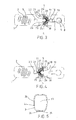
- the sharpener of the invention as shown in Figure 1 comprises a body part 1 depicted by a broken line in the figure and having a sharpening roll 2 mounted thereto on bearings.
- the sharpening roll 2 is a roll of a ceramic material and comprises a wedge-like groove 9 for receiving a blade 10 to be sharpened.
- the sharpening roll 2 and the groove 9 are best seen in Figure 3 .
- the body part 1 is surrounded by a longitudinal tubular outer cover 3, which covers the body part, and therefore only a small portion of the sharpening roll 2 (a portion of the sharpening roll groove) is visible in Figure 1 .
- a frame part 4 which is depicted by a broken line and may be referred to as an inner body, its structure being described further below.
- the body part 1 is attached to the bottom of the outer cover 3 by means of a resilient locking stud 5.
- the bottom of the outer cover 3 is provided with a hole 6 for receiving the locking stud 5.
- the locking stud 5 is surrounded by the hole 6 and the walls of the hole 6 prevent the body part 1 from moving in relation to the outer cover 3.
- the stud 5 is pressed through the hole 6 in the direction of arrow A to such an extent that it is released from the hole 6, after which the body part 1 may be moved in a longitudinal direction of the outer cover 3 and be removed from the outer cover.
- the locking stud 5 has been rendered flexible by connecting it to the bottom of the body part 1 by a flexible neck part 7.
- the body part 1 with its neck part 7 and stud 5 is made of plastic as a single piece.
- the neck part 7 is flexible because it is narrow and thin.
- the stud 5 and the neck part 7 are surrounded by a gap 8 similar to a key hole.
- the frame part 4 comprises a wedge-like guide groove 11 for receiving a blade 10 to be sharpened and for guiding it against the groove 9 of the sharpening roll 2 (the groove 9 is well visible in Figure 3 ).
- the guide groove 11 is meant to guide the blade 10 to a correct angle in relation to the sharpening roll 2 and to keep the blade 10 at the correct angle in relation to the sharpening roll when the sharpener is being used.
- the guide groove 11 has an angle ⁇ 1 which is 10 to 20 degrees, preferably about 15 degrees.
- a tip 12 of the guide groove 11, i.e. the bottom of the guide groove 11, sets at a height that leaves about 20 to 30% of the sharpening roll 2 visible when the sharpener is viewed from the angle of Figure 1 , i.e. from the side.
- the width of the guide groove 11 at the tip is about 1 mm when seen from the side.
- the width and the angle ⁇ 1 of the guide groove 11 are selected so that an empty space of about 2 to 4mm at the most is left between a guide groove wall and either one of the sides of the blade 10 even if the blade was not exactly vertical.
- the length of the guide groove 11 in cross-direction to the sharpener is 30mm and preferably within a range of 25 to 35mm.
- the guide groove 11 is accessible through an opening 13 made to the outer cover 3.
- the opening 13 is upward widening and has a spread angle that basically corresponds to the angle ⁇ 1 of the guide groove 11.
- the opening 13 has a bottom width L of 5 to 10mm.
- the shape and size of the opening 13 may differ from those presented.
- the frame 4 part is movable in a longitudinal direction of the body part 1 so that it is placeable from the position of Figure 1 to the position of Figure 2 , in which the guide groove 11 remains hidden inside the outer cover 3.
- the inner body contains a second wedge-like guide groove 14 which sets at the opening 13 of the outer cover above the sharpening roll 2.
- the guide groove 14 is wider than the guide groove 11 so as to be able to receive a blade 15 of an axe depicted with a broken line, i.e. a blade that is significantly wider than the blade 10 in Figure 1 .
- the axe blade 15 would not fit into the guide groove 11 of Figure 1 but would be wedged to its walls.
- the guide groove 14 has an angle ⁇ 2 corresponding to the angle ⁇ 1 of the guide groove 11.
- the tip 16 of the guide groove 14 sets at a height that leaves about 20 to 30% of the sharpening roll 2 visible when the sharpener is seen from the view angle of Figure 2 .
- the width of the guide groove 13 at the tip 16 is 2 to 3mm. The width is significantly greater than the width of the guide groove 11. It will be understood from Figures 1 and 2 that the opening 13 of the outer cover 3 must be wider than the width of the guide groove 14 and also that of the guide groove 11.
- the compression spring 17 keeps the frame part 4 springloaded either in positions of Figures 1 and 3 , or in those of Figures 2 and 4 , and the guide grooves 11 and 14 remain at the desired place above the sharpening roll 2 at locations depicted in Figures 1 and 2 when the sharpener is used for sharpening.
- the compression action in question of the compression spring 17 has been obtained by compressing it between protrusions 23 and 24 provided in the body part 1 and by allowing it to expand and curve to opposite lateral directions towards the stopper means 19 and 22.
- the compression spring 17 tends to expand towards the stopper means 19 of the body part 1 and to push the stopper member 18 towards the stopper means 19 of the body part, if an external force moves the compression spring to the right of line S - S defined by the protrusions 23, 24.
- Figure 3 shows a situation in which the periphery of the compression spring 17 presses the stopper member 18 against the stopper means 19 of the body part 1.
- FIG. 4 illustrates a situation in which the periphery of the compression spring 17 presses the stopper member 21 of the inner body against the stopper means 22 of the body part 1.
- the protrusions 23 and 24 enter into ends 25, 26 of the compression spring 17 and thus prevent the compression spring 17 from coming loose from its biased, compressed state.
- other kind of support means may be used for supporting the spring ends, such as recesses which the compression spring ends enter.
- Reference numerals 27 to 30 denote curved supports against which the periphery of the compression spring 17 may rest. In the case of Figure 3 the periphery of the compression spring 17 rests against supports 28 and 30, and in the case of Figure 4 against supports 27 and 29.
- the frame part 4 comprises a support surface 32 preventing the compression spring 17 from curving upward, see Figure 1
- the bottom of the body part 1 comprises a support surface 32 preventing the compression spring 17 from curving downward, see Figure 1 .
- the compression spring 17 sets between the support surfaces 31 and 32. Between the stopper members 18 and 21 of the inner body there is a gap corresponding to the thickness of the compression spring 17 and hence there is no space left around the compression spring. This provides the compression spring 17 with a controlled support and the inner body 4 moves between the positions shown in Figures 1 and 2 in a controlled manner without a risk of the ends of the compression spring 17 getting loose from the protrusions 23, 24 of the body part 1.
- the frame part 4 is made to move from the first position of Figure 1 to the second position of Figure 2 by pushing the frame part at the end 33 of the sharpener by an external force into the direction of arrow B.
- the external force subjected to the stopper member 18 during pushing must exceed the reverse-direction force subjected to the stopper member 18 by the compression spring 17 until the compression spring 17 reaches line S - S of the protrusions 23, 24, see Figure 3 .
- the frame part 4 can be made to move from the second position shown in Figure 2 to the first position shown in Figure 1 by applying an external force to a frame part end 34 of the sharpener to push it towards arrow C.
- the external force acting on the stopper member 21 must exceed the reverse-direction force subjected to the stopper member 21 by the compression spring 17 until the compression spring 17 reaches line S - S of the protrusions 23, 24.
- Figure 5 shows the sharpener from the other end.
- the tubular outer cover 3 acts as a guide means for the movement of the frame part 4.
- Reference numeral 20 indicates a reinforcement surrounding the opening 13 in the outer cover 3 and stiffening the outer cover 3.
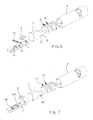
- Figure 6 is an explosion view of the sharpener. The figure shows the components of the sharpener in detail.
- the sharpener is made of plastic by injection moulding.
- the outer cover 3 is preferably a mixture of acrylonitrile butadiene styrene (ABS) and polycarbonate (PC). Alternatively, it may be ABS or PC, for example.
- ABS acrylonitrile butadiene styrene
- PC polycarbonate
- the bottom of the outer cover 3 is preferably provided with protrusions 35 made of an elastomer material; alternatively, the bottom of the outer cover 3 may be provided with a larger surface made of thermoplastic elastomer (TPE), i.e. a rubber-like thermoplast or a mixture of plastic and rubber.
- TPE thermoplastic elastomer
- the body part 1 and the frame part 4 are preferably of ABS. Alternatively, they may be made of polypropylene (PP) or polyoxymethylene (POM), for example.
- the sharpener is used by placing it onto a surface, by holding the outer cover 3 and pushing the blade 10 to be sharpened back and forth in the guide groove 11 or, if the blade 15 is wide, back and forth in the guide groove 14.
- the back and forth movement makes the sharpening roll 2 rotate and as the roll rotates it sharpens the blade 10, 15 of the tool.
- Figure 7 shows a second embodiment of the sharpener of the invention.
- like reference numerals are used as in Figure 6 for like components.
- the stopper members 18 and 21 of the frame part 4 of Figure 6 are replaced by a pin-like part 102' (which is also a stopper member) and that the stopper means 100', 101' of the body part 1' of Figure 7 look slightly different than the stopper means 19, 22 of Figure 6 .
- the pin-like part in Figure 7 is a steel pin 102' and the stopper means 100', 101' are magnets.
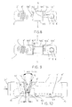
- Figures 8 and 9 disclose the operation of the steel pin 102' and the magnets 100', 101'.
- Figure 8 corresponds to the view of Figure 3 .
- the steel pin 102' of the frame part (cf. the frame part 4' of Figure 7 ) is against the magnet 101' of the body part 1' and keeps the frame part in a position in which its narrower groove 11' is above the sharpening roll 2'.
- the magnet 101' draws the steel pin 102' towards itself and keeps the frame part 4' in the first position by magnetic force.
- Reference numerals 103' and 104' depict partition walls supporting the magnets 100' and 101', respectively.
- Reference numerals 105' depict stiffener parts for stiffening the body part 1'.
- Figure 9 corresponds to the view of Figure 4 .
- the steel pin 102' of the frame part (cf. the frame part 4 in Figures 7 and 10 ) is against the magnet 100'of the body part 1' and keeps the frame part in a position in which its wider groove 14' is above the sharpening roll 2'.
- Figure 10 shows the position of use in question, which corresponds to the position of the frame part 4 in Figure 2 .
- Like reference numerals are used in Figure 10 as in Figure 2 for like components. According to embodiments of Figures 7 to 10 , it is feasible to replace the magnets 100', 101' by steel pieces, in which case the steel pin 102' is replaced by a piece of magnet.
- the outer cover 3, 3' is not necessarily needed, although it is highly recommended, because it provides a number of advantages: it supports the frame part 4, 4' (to the inner body) and keeps the frame part against the body part 1, 1', it is easy to take hold of by hand when the sharpener is used and it allows the sharpener to be provided with an excellent outer appearance.
- the frame part 4, 4' does not need to be supported by a spring or a magnet in its different positions of use, although this is extremely recommendable from the point of view of use of the sharpener, because a spring or magnet support allows to provide the necessary lateral support of the blade 10, 15 to be sharpened against the walls of the guide grooves 11, 14.
- the guide grooves 11 and 14 do not necessarily have to be wedge-like, although a wedge shape is most preferable for supporting the blade to be sharpened. Instead of a ceramic sharpening roll, a diamond sharpening roll may be used.
Landscapes
- Engineering & Computer Science (AREA)
- Mechanical Engineering (AREA)
- Finish Polishing, Edge Sharpening, And Grinding By Specific Grinding Devices (AREA)
Priority Applications (1)
| Application Number | Priority Date | Filing Date | Title |
|---|---|---|---|
| PL12182581T PL2564983T3 (pl) | 2011-09-01 | 2012-08-31 | Ostrzarka |
Applications Claiming Priority (2)
| Application Number | Priority Date | Filing Date | Title |
|---|---|---|---|
| FI20115856A FI20115856A0 (fi) | 2011-09-01 | 2011-09-01 | Teroitin |
| FI20116306A FI20116306A7 (fi) | 2011-09-01 | 2011-12-22 | Teroitin |
Publications (3)
| Publication Number | Publication Date |
|---|---|
| EP2564983A2 true EP2564983A2 (de) | 2013-03-06 |
| EP2564983A3 EP2564983A3 (de) | 2014-09-17 |
| EP2564983B1 EP2564983B1 (de) | 2015-09-16 |
Family
ID=46924256
Family Applications (1)
| Application Number | Title | Priority Date | Filing Date |
|---|---|---|---|
| EP12182581.4A Active EP2564983B1 (de) | 2011-09-01 | 2012-08-31 | Schärfer |
Country Status (5)
| Country | Link |
|---|---|
| US (1) | US8864554B2 (de) |
| EP (1) | EP2564983B1 (de) |
| DK (1) | DK2564983T3 (de) |
| FI (1) | FI20116306A7 (de) |
| PL (1) | PL2564983T3 (de) |
Cited By (2)
| Publication number | Priority date | Publication date | Assignee | Title |
|---|---|---|---|---|
| CN103659475A (zh) * | 2013-11-30 | 2014-03-26 | 无锡市优耐特石化装备有限公司 | 一种双面磨刀装置 |
| CN114173995A (zh) * | 2019-05-17 | 2022-03-11 | 德瑞克斯有限公司 | 具有可倾斜磨锐台的工具磨锐机 |
Families Citing this family (11)
| Publication number | Priority date | Publication date | Assignee | Title |
|---|---|---|---|---|
| US9469014B2 (en) | 2013-11-26 | 2016-10-18 | Wolff Industries, Inc. | Conditioning device for conditioning a blade |
| US9950401B2 (en) * | 2013-12-12 | 2018-04-24 | Tormek Ab | Jig means for a grinding machine and a grinding machine comprising the jig means |
| US20160367672A1 (en) * | 2014-03-03 | 2016-12-22 | University Of Southern California | Methods and systems for treating tumors |
| US9649749B2 (en) * | 2015-01-16 | 2017-05-16 | Edgecraft Corporation | Manual sharpener |
| US11491602B2 (en) | 2016-02-12 | 2022-11-08 | Darex, Llc | Powered sharpener with user directed indicator mechanism |
| WO2020081312A1 (en) * | 2018-10-16 | 2020-04-23 | Darex, Llc | Powered sharpener with user directed indicator mechanism |
| US11945072B1 (en) * | 2019-06-04 | 2024-04-02 | Bryan Chad Thomas | High speed drill bit sharpener |
| US11279003B1 (en) * | 2020-01-03 | 2022-03-22 | Angle Pro Sharpener LLC | Knife sharpeners with angle gauge |
| CN112518601B (zh) * | 2020-12-17 | 2025-03-14 | 深圳欧欧优智能健康家居有限公司 | 磨刀器 |
| USD1067011S1 (en) * | 2023-01-31 | 2025-03-18 | Fiskars Finland Oy Ab | Knife sharpener |
| USD1034140S1 (en) * | 2024-04-12 | 2024-07-09 | Wenfeng Li | Knife sharpener |
Family Cites Families (44)
| Publication number | Priority date | Publication date | Assignee | Title |
|---|---|---|---|---|
| US1753510A (en) * | 1926-05-27 | 1930-04-08 | Joseph R Gibson | Razor-blade sharpener |
| US1767091A (en) | 1929-03-07 | 1930-06-24 | Robert E Millsap | Knife sharpener |
| US2448629A (en) | 1945-09-10 | 1948-09-07 | Benjamin F Schmidt | Knife sharpener |
| US2431188A (en) * | 1946-02-20 | 1947-11-18 | Howard C Miller | Knife sharpening device |
| US2457714A (en) | 1947-05-12 | 1948-12-28 | William R Pancoast | Knife sharpener |
| US2495814A (en) * | 1947-12-13 | 1950-01-31 | Rayflex Company Inc | Knife sharpener |
| US2544777A (en) * | 1948-11-26 | 1951-03-13 | Joseph A Cahil | Knife sharpener |
| BE487564A (de) * | 1949-02-16 | |||
| US2841926A (en) | 1954-05-06 | 1958-07-08 | Supreme Products Corp | Knife sharpener casing |
| US2749678A (en) * | 1954-09-09 | 1956-06-12 | Charles R Jahn | Knife sharpener |
| US4228703A (en) | 1979-03-02 | 1980-10-21 | Moss Donald C | Device for sharpening arrowheads |
| GB2123323B (en) | 1982-04-30 | 1985-12-18 | Hitachi Maxell | Blade sharpener |
| AT377938B (de) | 1983-06-24 | 1985-05-28 | Philips Nv | Schleifapparat |
| US5005319A (en) | 1984-03-12 | 1991-04-09 | Edgecraft Corporation | Knife sharpener |
| US4807399A (en) * | 1984-03-12 | 1989-02-28 | Edgecraft Corp. | Method and apparatus for sharpening a knife |
| US4897965A (en) | 1984-03-12 | 1990-02-06 | Friel Daniel D | Knife sharpening apparatus |
| US5404679A (en) | 1984-03-12 | 1995-04-11 | Edgecraft Corporation | Portable manual sharpener for knives and the like |
| USD287095S (en) | 1984-03-21 | 1986-12-09 | Kaman Sciences Corporation | Sharpening stone holder |
| US4696129A (en) | 1984-05-24 | 1987-09-29 | Roberts Timothy A | Honing device |
| FI74230C (sv) | 1986-02-04 | 1988-01-11 | Fiskars Ab Oy | Anordning för skärpning av knivar. |
| USD322169S (en) | 1987-09-23 | 1991-12-10 | Mietelski Gerard J | Holder for cams and related cam lifters |
| FI880233L (fi) * | 1988-01-20 | 1989-07-21 | Fiskars Ab Oy | Anordning foer skaerpning av knivar. |
| USD352880S (en) | 1993-03-01 | 1994-11-29 | Edge Specialties, Inc. | Ice skate blade sharpener |
| US5620359A (en) * | 1994-10-07 | 1997-04-15 | Cuisine De France, Ltd. | Knife sharpener |
| USD372180S (en) | 1995-01-17 | 1996-07-30 | Powell David G | Combined whetstone and housing |
| USD372580S (en) | 1995-01-31 | 1996-08-13 | Chipman Sr Raymond R | Storage case for gun powder and shot |
| AU713972B2 (en) | 1996-07-09 | 1999-12-16 | Edgecraft Corporation | Versatile manual sharpener |
| US6012971A (en) * | 1997-03-14 | 2000-01-11 | Edgecraft Corporation | Sharpening apparatus |
| US6039642A (en) | 1998-09-15 | 2000-03-21 | Collins; Walter W. | Blade sharpener |
| US6398633B1 (en) * | 2000-06-02 | 2002-06-04 | Mcgowan Manufacturing Co. | Two stage knife sharpener |
| US6875093B2 (en) | 2002-10-15 | 2005-04-05 | Edgecraft Corporation | Sharpening device |
| US6802763B1 (en) * | 2002-10-25 | 2004-10-12 | Salton, Inc. | Apparatus for sharpening blades |
| US6866569B2 (en) * | 2002-11-14 | 2005-03-15 | Cozzini, Inc. | Blade sharpening apparatus |
| US6846229B1 (en) | 2003-01-09 | 2005-01-25 | World Kitchen (Ghc), Llc | Handheld retractable pull-through knife sharpener |
| CN1771109B (zh) | 2003-03-27 | 2011-09-21 | 埃奇克拉夫特公司 | 用于沿切削刃进行刃磨并且制作微刀片的精密装置 |
| US7517275B2 (en) * | 2003-03-27 | 2009-04-14 | Edgecraft Corp. | Apparatus for precision steeling/conditioning of knife edges |
| US20050221742A1 (en) | 2004-03-30 | 2005-10-06 | Su Yeong M | Windshield wiper blade sharpener device |
| USD509355S1 (en) | 2004-05-18 | 2005-09-13 | Stanley A. Pleskunas | Fishing fly storage box with sliding cover |
| USD550532S1 (en) | 2005-12-30 | 2007-09-11 | Sports And Recreation Technologies, Llc | Arrowhead hone |
| US8221199B2 (en) | 2007-01-11 | 2012-07-17 | Smith Abrasives, Inc | Abrasive sharpener |
| US7740522B2 (en) | 2007-07-09 | 2010-06-22 | National Presto Industries, Inc. | Knife sharpener |
| US20090064822A1 (en) | 2007-09-07 | 2009-03-12 | Bonnie Sterngold | Pocket sharpener for knives |
| AU2009223635B2 (en) | 2008-03-11 | 2014-08-07 | Edgecraft Corporation | Sharpener for knives with widely different edge angles |
| DK2544856T3 (da) | 2010-03-12 | 2022-08-15 | Edgecraft Corp | Knivslibemaskiner til asiatiske og europæiske/amerikanske knive |
-
2011
- 2011-12-22 FI FI20116306A patent/FI20116306A7/fi not_active Application Discontinuation
-
2012
- 2012-08-30 US US13/599,888 patent/US8864554B2/en not_active Expired - Fee Related
- 2012-08-31 EP EP12182581.4A patent/EP2564983B1/de active Active
- 2012-08-31 DK DK12182581.4T patent/DK2564983T3/en active
- 2012-08-31 PL PL12182581T patent/PL2564983T3/pl unknown
Non-Patent Citations (1)
| Title |
|---|
| None |
Cited By (4)
| Publication number | Priority date | Publication date | Assignee | Title |
|---|---|---|---|---|
| CN103659475A (zh) * | 2013-11-30 | 2014-03-26 | 无锡市优耐特石化装备有限公司 | 一种双面磨刀装置 |
| CN103659475B (zh) * | 2013-11-30 | 2016-04-13 | 无锡市优耐特石化装备有限公司 | 一种双面磨刀装置 |
| CN114173995A (zh) * | 2019-05-17 | 2022-03-11 | 德瑞克斯有限公司 | 具有可倾斜磨锐台的工具磨锐机 |
| CN114173995B (zh) * | 2019-05-17 | 2023-12-12 | 德瑞克斯有限公司 | 具有可倾斜磨锐台的工具磨锐机 |
Also Published As
| Publication number | Publication date |
|---|---|
| EP2564983B1 (de) | 2015-09-16 |
| EP2564983A3 (de) | 2014-09-17 |
| US8864554B2 (en) | 2014-10-21 |
| FI20116306L (fi) | 2013-03-02 |
| DK2564983T3 (en) | 2015-10-19 |
| US20130095736A1 (en) | 2013-04-18 |
| PL2564983T3 (pl) | 2016-01-29 |
| FI20116306A7 (fi) | 2013-03-02 |
Similar Documents
| Publication | Publication Date | Title |
|---|---|---|
| EP2564983B1 (de) | Schärfer | |
| EP3406159A1 (de) | Kartenhalter | |
| EP2934829B1 (de) | Rasierer | |
| EP2934824B1 (de) | Rasierer | |
| US9162627B2 (en) | Snug-fit item holder | |
| EP2934826B1 (de) | Rasierer | |
| CN115256494B (zh) | 刀片接纳件组件和切割装置 | |
| US12496687B2 (en) | Sharpening sheath adapted to receive a knife, and combination of such a sheath and a knife | |
| US20020162849A1 (en) | Structure art design knife blade container | |
| US20130147104A1 (en) | Pencil sharpener | |
| US10081215B2 (en) | Compact ballpoint pen | |
| KR101757399B1 (ko) | 카드 수납기능이 있는 휴대폰 보호케이스 | |
| US20190283016A1 (en) | Manual metering device | |
| EP1040016B1 (de) | Stiftspitzmaschine | |
| CN108892097B (zh) | 装配有高度可调节的分配头的饮料分配机 | |
| US20110011230A1 (en) | Device for producing a hole in a sheet-shaped material | |
| JP3181827U (ja) | 名刺入れ | |
| US3724961A (en) | Writing device having a retractable writing element | |
| US2976986A (en) | Magazine for applying razor blades to a holder | |
| CN203780144U (zh) | 一种能够收纳中心针的圆规 | |
| KR101929156B1 (ko) | 립스틱 용기 | |
| US20180002129A1 (en) | Packing tape dispenser | |
| KR101340326B1 (ko) | 채혈침 저장장치 | |
| US1159487A (en) | Razor honing and stropping device. | |
| CN210852269U (zh) | 电子装置保持器 |
Legal Events
| Date | Code | Title | Description |
|---|---|---|---|
| PUAI | Public reference made under article 153(3) epc to a published international application that has entered the european phase |
Free format text: ORIGINAL CODE: 0009012 |
|
| AK | Designated contracting states |
Kind code of ref document: A2 Designated state(s): AL AT BE BG CH CY CZ DE DK EE ES FI FR GB GR HR HU IE IS IT LI LT LU LV MC MK MT NL NO PL PT RO RS SE SI SK SM TR |
|
| AX | Request for extension of the european patent |
Extension state: BA ME |
|
| PUAL | Search report despatched |
Free format text: ORIGINAL CODE: 0009013 |
|
| AK | Designated contracting states |
Kind code of ref document: A3 Designated state(s): AL AT BE BG CH CY CZ DE DK EE ES FI FR GB GR HR HU IE IS IT LI LT LU LV MC MK MT NL NO PL PT RO RS SE SI SK SM TR |
|
| AX | Request for extension of the european patent |
Extension state: BA ME |
|
| RIC1 | Information provided on ipc code assigned before grant |
Ipc: B24B 3/36 20060101ALI20140812BHEP Ipc: B24D 15/08 20060101AFI20140812BHEP Ipc: B24B 3/54 20060101ALI20140812BHEP |
|
| 17P | Request for examination filed |
Effective date: 20141219 |
|
| RBV | Designated contracting states (corrected) |
Designated state(s): AL AT BE BG CH CY CZ DE DK EE ES FI FR GB GR HR HU IE IS IT LI LT LU LV MC MK MT NL NO PL PT RO RS SE SI SK SM TR |
|
| GRAP | Despatch of communication of intention to grant a patent |
Free format text: ORIGINAL CODE: EPIDOSNIGR1 |
|
| INTG | Intention to grant announced |
Effective date: 20150515 |
|
| GRAS | Grant fee paid |
Free format text: ORIGINAL CODE: EPIDOSNIGR3 |
|
| GRAA | (expected) grant |
Free format text: ORIGINAL CODE: 0009210 |
|
| AK | Designated contracting states |
Kind code of ref document: B1 Designated state(s): AL AT BE BG CH CY CZ DE DK EE ES FI FR GB GR HR HU IE IS IT LI LT LU LV MC MK MT NL NO PL PT RO RS SE SI SK SM TR |
|
| REG | Reference to a national code |
Ref country code: GB Ref legal event code: FG4D |
|
| RIN1 | Information on inventor provided before grant (corrected) |
Inventor name: HUHTALA, JUHA Inventor name: HUTTUNEN, AARO Inventor name: KUNNAS, KARI Inventor name: LYYTIKAEINEN, SAMI Inventor name: MASALIN, PETTERI Inventor name: SALOJAERVI, JOUNI Inventor name: VAENTTILAE, OLLI-PEKKA |
|
| REG | Reference to a national code |
Ref country code: CH Ref legal event code: EP |
|
| REG | Reference to a national code |
Ref country code: IE Ref legal event code: FG4D |
|
| REG | Reference to a national code |
Ref country code: AT Ref legal event code: REF Ref document number: 749412 Country of ref document: AT Kind code of ref document: T Effective date: 20151015 |
|
| REG | Reference to a national code |
Ref country code: DK Ref legal event code: T3 Effective date: 20151014 |
|
| REG | Reference to a national code |
Ref country code: DE Ref legal event code: R096 Ref document number: 602012010584 Country of ref document: DE |
|
| REG | Reference to a national code |
Ref country code: EE Ref legal event code: FG4A Ref document number: E011118 Country of ref document: EE Effective date: 20151026 |
|
| REG | Reference to a national code |
Ref country code: SE Ref legal event code: TRGR |
|
| REG | Reference to a national code |
Ref country code: NO Ref legal event code: T2 Effective date: 20150916 |
|
| REG | Reference to a national code |
Ref country code: NL Ref legal event code: MP Effective date: 20150916 |
|
| PG25 | Lapsed in a contracting state [announced via postgrant information from national office to epo] |
Ref country code: GR Free format text: LAPSE BECAUSE OF FAILURE TO SUBMIT A TRANSLATION OF THE DESCRIPTION OR TO PAY THE FEE WITHIN THE PRESCRIBED TIME-LIMIT Effective date: 20151217 |
|
| REG | Reference to a national code |
Ref country code: AT Ref legal event code: MK05 Ref document number: 749412 Country of ref document: AT Kind code of ref document: T Effective date: 20150916 |
|
| PG25 | Lapsed in a contracting state [announced via postgrant information from national office to epo] |
Ref country code: HR Free format text: LAPSE BECAUSE OF FAILURE TO SUBMIT A TRANSLATION OF THE DESCRIPTION OR TO PAY THE FEE WITHIN THE PRESCRIBED TIME-LIMIT Effective date: 20150916 Ref country code: RS Free format text: LAPSE BECAUSE OF FAILURE TO SUBMIT A TRANSLATION OF THE DESCRIPTION OR TO PAY THE FEE WITHIN THE PRESCRIBED TIME-LIMIT Effective date: 20150916 |
|
| PG25 | Lapsed in a contracting state [announced via postgrant information from national office to epo] |
Ref country code: NL Free format text: LAPSE BECAUSE OF FAILURE TO SUBMIT A TRANSLATION OF THE DESCRIPTION OR TO PAY THE FEE WITHIN THE PRESCRIBED TIME-LIMIT Effective date: 20150916 |
|
| PG25 | Lapsed in a contracting state [announced via postgrant information from national office to epo] |
Ref country code: ES Free format text: LAPSE BECAUSE OF FAILURE TO SUBMIT A TRANSLATION OF THE DESCRIPTION OR TO PAY THE FEE WITHIN THE PRESCRIBED TIME-LIMIT Effective date: 20150916 Ref country code: SK Free format text: LAPSE BECAUSE OF FAILURE TO SUBMIT A TRANSLATION OF THE DESCRIPTION OR TO PAY THE FEE WITHIN THE PRESCRIBED TIME-LIMIT Effective date: 20150916 Ref country code: IS Free format text: LAPSE BECAUSE OF FAILURE TO SUBMIT A TRANSLATION OF THE DESCRIPTION OR TO PAY THE FEE WITHIN THE PRESCRIBED TIME-LIMIT Effective date: 20160116 |
|
| PG25 | Lapsed in a contracting state [announced via postgrant information from national office to epo] |
Ref country code: PT Free format text: LAPSE BECAUSE OF FAILURE TO SUBMIT A TRANSLATION OF THE DESCRIPTION OR TO PAY THE FEE WITHIN THE PRESCRIBED TIME-LIMIT Effective date: 20160118 Ref country code: RO Free format text: LAPSE BECAUSE OF FAILURE TO SUBMIT A TRANSLATION OF THE DESCRIPTION OR TO PAY THE FEE WITHIN THE PRESCRIBED TIME-LIMIT Effective date: 20150916 Ref country code: AT Free format text: LAPSE BECAUSE OF FAILURE TO SUBMIT A TRANSLATION OF THE DESCRIPTION OR TO PAY THE FEE WITHIN THE PRESCRIBED TIME-LIMIT Effective date: 20150916 |
|
| REG | Reference to a national code |
Ref country code: DE Ref legal event code: R097 Ref document number: 602012010584 Country of ref document: DE |
|
| PLBE | No opposition filed within time limit |
Free format text: ORIGINAL CODE: 0009261 |
|
| STAA | Information on the status of an ep patent application or granted ep patent |
Free format text: STATUS: NO OPPOSITION FILED WITHIN TIME LIMIT |
|
| 26N | No opposition filed |
Effective date: 20160617 |
|
| REG | Reference to a national code |
Ref country code: FR Ref legal event code: PLFP Year of fee payment: 5 |
|
| PG25 | Lapsed in a contracting state [announced via postgrant information from national office to epo] |
Ref country code: SI Free format text: LAPSE BECAUSE OF FAILURE TO SUBMIT A TRANSLATION OF THE DESCRIPTION OR TO PAY THE FEE WITHIN THE PRESCRIBED TIME-LIMIT Effective date: 20150916 |
|
| PG25 | Lapsed in a contracting state [announced via postgrant information from national office to epo] |
Ref country code: BE Free format text: LAPSE BECAUSE OF FAILURE TO SUBMIT A TRANSLATION OF THE DESCRIPTION OR TO PAY THE FEE WITHIN THE PRESCRIBED TIME-LIMIT Effective date: 20150916 |
|
| PG25 | Lapsed in a contracting state [announced via postgrant information from national office to epo] |
Ref country code: MC Free format text: LAPSE BECAUSE OF FAILURE TO SUBMIT A TRANSLATION OF THE DESCRIPTION OR TO PAY THE FEE WITHIN THE PRESCRIBED TIME-LIMIT Effective date: 20150916 |
|
| REG | Reference to a national code |
Ref country code: CH Ref legal event code: PL |
|
| PG25 | Lapsed in a contracting state [announced via postgrant information from national office to epo] |
Ref country code: LI Free format text: LAPSE BECAUSE OF NON-PAYMENT OF DUE FEES Effective date: 20160831 Ref country code: CH Free format text: LAPSE BECAUSE OF NON-PAYMENT OF DUE FEES Effective date: 20160831 |
|
| REG | Reference to a national code |
Ref country code: IE Ref legal event code: MM4A |
|
| PG25 | Lapsed in a contracting state [announced via postgrant information from national office to epo] |
Ref country code: IE Free format text: LAPSE BECAUSE OF NON-PAYMENT OF DUE FEES Effective date: 20160831 |
|
| REG | Reference to a national code |
Ref country code: FR Ref legal event code: PLFP Year of fee payment: 6 |
|
| PG25 | Lapsed in a contracting state [announced via postgrant information from national office to epo] |
Ref country code: LU Free format text: LAPSE BECAUSE OF NON-PAYMENT OF DUE FEES Effective date: 20160831 |
|
| PG25 | Lapsed in a contracting state [announced via postgrant information from national office to epo] |
Ref country code: HU Free format text: LAPSE BECAUSE OF FAILURE TO SUBMIT A TRANSLATION OF THE DESCRIPTION OR TO PAY THE FEE WITHIN THE PRESCRIBED TIME-LIMIT; INVALID AB INITIO Effective date: 20120831 Ref country code: CY Free format text: LAPSE BECAUSE OF FAILURE TO SUBMIT A TRANSLATION OF THE DESCRIPTION OR TO PAY THE FEE WITHIN THE PRESCRIBED TIME-LIMIT Effective date: 20150916 Ref country code: SM Free format text: LAPSE BECAUSE OF FAILURE TO SUBMIT A TRANSLATION OF THE DESCRIPTION OR TO PAY THE FEE WITHIN THE PRESCRIBED TIME-LIMIT Effective date: 20150916 |
|
| PG25 | Lapsed in a contracting state [announced via postgrant information from national office to epo] |
Ref country code: MK Free format text: LAPSE BECAUSE OF FAILURE TO SUBMIT A TRANSLATION OF THE DESCRIPTION OR TO PAY THE FEE WITHIN THE PRESCRIBED TIME-LIMIT Effective date: 20150916 Ref country code: MT Free format text: LAPSE BECAUSE OF NON-PAYMENT OF DUE FEES Effective date: 20160831 Ref country code: TR Free format text: LAPSE BECAUSE OF FAILURE TO SUBMIT A TRANSLATION OF THE DESCRIPTION OR TO PAY THE FEE WITHIN THE PRESCRIBED TIME-LIMIT Effective date: 20150916 |
|
| PG25 | Lapsed in a contracting state [announced via postgrant information from national office to epo] |
Ref country code: BG Free format text: LAPSE BECAUSE OF FAILURE TO SUBMIT A TRANSLATION OF THE DESCRIPTION OR TO PAY THE FEE WITHIN THE PRESCRIBED TIME-LIMIT Effective date: 20150916 |
|
| REG | Reference to a national code |
Ref country code: FR Ref legal event code: PLFP Year of fee payment: 7 |
|
| PG25 | Lapsed in a contracting state [announced via postgrant information from national office to epo] |
Ref country code: AL Free format text: LAPSE BECAUSE OF FAILURE TO SUBMIT A TRANSLATION OF THE DESCRIPTION OR TO PAY THE FEE WITHIN THE PRESCRIBED TIME-LIMIT Effective date: 20150916 |
|
| REG | Reference to a national code |
Ref country code: EE Ref legal event code: HC1A Ref document number: E011118 Country of ref document: EE |
|
| PGFP | Annual fee paid to national office [announced via postgrant information from national office to epo] |
Ref country code: LT Payment date: 20200821 Year of fee payment: 9 Ref country code: CZ Payment date: 20200803 Year of fee payment: 9 Ref country code: EE Payment date: 20200826 Year of fee payment: 9 |
|
| PGFP | Annual fee paid to national office [announced via postgrant information from national office to epo] |
Ref country code: IT Payment date: 20200820 Year of fee payment: 9 Ref country code: LV Payment date: 20200820 Year of fee payment: 9 |
|
| REG | Reference to a national code |
Ref country code: EE Ref legal event code: MM4A Ref document number: E011118 Country of ref document: EE Effective date: 20210831 |
|
| REG | Reference to a national code |
Ref country code: LT Ref legal event code: MM4D Effective date: 20210831 |
|
| PG25 | Lapsed in a contracting state [announced via postgrant information from national office to epo] |
Ref country code: LV Free format text: LAPSE BECAUSE OF NON-PAYMENT OF DUE FEES Effective date: 20210831 Ref country code: EE Free format text: LAPSE BECAUSE OF NON-PAYMENT OF DUE FEES Effective date: 20210831 Ref country code: CZ Free format text: LAPSE BECAUSE OF NON-PAYMENT OF DUE FEES Effective date: 20210831 |
|
| PG25 | Lapsed in a contracting state [announced via postgrant information from national office to epo] |
Ref country code: LT Free format text: LAPSE BECAUSE OF NON-PAYMENT OF DUE FEES Effective date: 20210831 Ref country code: IT Free format text: LAPSE BECAUSE OF NON-PAYMENT OF DUE FEES Effective date: 20210831 |
|
| P01 | Opt-out of the competence of the unified patent court (upc) registered |
Effective date: 20230825 |
|
| PGFP | Annual fee paid to national office [announced via postgrant information from national office to epo] |
Ref country code: FI Payment date: 20250820 Year of fee payment: 14 |
|
| PGFP | Annual fee paid to national office [announced via postgrant information from national office to epo] |
Ref country code: DK Payment date: 20250826 Year of fee payment: 14 Ref country code: DE Payment date: 20250819 Year of fee payment: 14 |
|
| PGFP | Annual fee paid to national office [announced via postgrant information from national office to epo] |
Ref country code: NO Payment date: 20250821 Year of fee payment: 14 |
|
| PGFP | Annual fee paid to national office [announced via postgrant information from national office to epo] |
Ref country code: PL Payment date: 20250804 Year of fee payment: 14 |
|
| PGFP | Annual fee paid to national office [announced via postgrant information from national office to epo] |
Ref country code: GB Payment date: 20250819 Year of fee payment: 14 |
|
| PGFP | Annual fee paid to national office [announced via postgrant information from national office to epo] |
Ref country code: FR Payment date: 20250818 Year of fee payment: 14 |
|
| PGFP | Annual fee paid to national office [announced via postgrant information from national office to epo] |
Ref country code: SE Payment date: 20250819 Year of fee payment: 14 |