EP2564914B1 - Verfahren und Systeme zur Gewinnung von CO2 - Google Patents
Verfahren und Systeme zur Gewinnung von CO2 Download PDFInfo
- Publication number
- EP2564914B1 EP2564914B1 EP12180636.8A EP12180636A EP2564914B1 EP 2564914 B1 EP2564914 B1 EP 2564914B1 EP 12180636 A EP12180636 A EP 12180636A EP 2564914 B1 EP2564914 B1 EP 2564914B1
- Authority
- EP
- European Patent Office
- Prior art keywords
- chamber
- carbon dioxide
- vacuum chamber
- contactor
- air
- Prior art date
- Legal status (The legal status is an assumption and is not a legal conclusion. Google has not performed a legal analysis and makes no representation as to the accuracy of the status listed.)
- Active
Links
- 238000000034 method Methods 0.000 title claims description 48
- CURLTUGMZLYLDI-UHFFFAOYSA-N Carbon dioxide Chemical compound O=C=O CURLTUGMZLYLDI-UHFFFAOYSA-N 0.000 claims description 284
- 229910002092 carbon dioxide Inorganic materials 0.000 claims description 142
- 239000001569 carbon dioxide Substances 0.000 claims description 142
- 239000000463 material Substances 0.000 claims description 53
- 239000002274 desiccant Substances 0.000 claims description 49
- XLYOFNOQVPJJNP-UHFFFAOYSA-N water Substances O XLYOFNOQVPJJNP-UHFFFAOYSA-N 0.000 claims description 38
- 239000007787 solid Substances 0.000 claims description 27
- 239000002808 molecular sieve Substances 0.000 claims description 16
- URGAHOPLAPQHLN-UHFFFAOYSA-N sodium aluminosilicate Chemical compound [Na+].[Al+3].[O-][Si]([O-])=O.[O-][Si]([O-])=O URGAHOPLAPQHLN-UHFFFAOYSA-N 0.000 claims description 16
- 239000002826 coolant Substances 0.000 claims description 13
- 230000007704 transition Effects 0.000 claims description 10
- 238000001816 cooling Methods 0.000 claims description 5
- 238000010438 heat treatment Methods 0.000 claims description 4
- 238000007789 sealing Methods 0.000 claims description 3
- 239000007789 gas Substances 0.000 description 15
- 230000000712 assembly Effects 0.000 description 12
- 238000000429 assembly Methods 0.000 description 12
- 239000003921 oil Substances 0.000 description 12
- 238000010586 diagram Methods 0.000 description 11
- 230000008929 regeneration Effects 0.000 description 8
- 238000011069 regeneration method Methods 0.000 description 8
- IJGRMHOSHXDMSA-UHFFFAOYSA-N Atomic nitrogen Chemical compound N#N IJGRMHOSHXDMSA-UHFFFAOYSA-N 0.000 description 6
- 238000011084 recovery Methods 0.000 description 6
- 238000004519 manufacturing process Methods 0.000 description 5
- 239000011148 porous material Substances 0.000 description 5
- 239000006227 byproduct Substances 0.000 description 4
- 239000000284 extract Substances 0.000 description 3
- 229910052757 nitrogen Inorganic materials 0.000 description 3
- 238000001179 sorption measurement Methods 0.000 description 3
- 229910052783 alkali metal Inorganic materials 0.000 description 2
- 239000010779 crude oil Substances 0.000 description 2
- 238000000605 extraction Methods 0.000 description 2
- 239000007788 liquid Substances 0.000 description 2
- 239000003129 oil well Substances 0.000 description 2
- 230000001172 regenerating effect Effects 0.000 description 2
- 239000010457 zeolite Substances 0.000 description 2
- 229910021536 Zeolite Inorganic materials 0.000 description 1
- 239000002156 adsorbate Substances 0.000 description 1
- 239000003463 adsorbent Substances 0.000 description 1
- 238000007664 blowing Methods 0.000 description 1
- 238000004891 communication Methods 0.000 description 1
- 125000004122 cyclic group Chemical group 0.000 description 1
- 238000000354 decomposition reaction Methods 0.000 description 1
- 230000003247 decreasing effect Effects 0.000 description 1
- 238000003795 desorption Methods 0.000 description 1
- HNPSIPDUKPIQMN-UHFFFAOYSA-N dioxosilane;oxo(oxoalumanyloxy)alumane Chemical compound O=[Si]=O.O=[Al]O[Al]=O HNPSIPDUKPIQMN-UHFFFAOYSA-N 0.000 description 1
- 238000001035 drying Methods 0.000 description 1
- 230000007613 environmental effect Effects 0.000 description 1
- 230000007717 exclusion Effects 0.000 description 1
- 239000012530 fluid Substances 0.000 description 1
- 238000007710 freezing Methods 0.000 description 1
- 230000008014 freezing Effects 0.000 description 1
- 230000006870 function Effects 0.000 description 1
- 150000008282 halocarbons Chemical class 0.000 description 1
- 239000000047 product Substances 0.000 description 1
- 230000000630 rising effect Effects 0.000 description 1
- 230000000007 visual effect Effects 0.000 description 1
Images


Classifications
-
- B—PERFORMING OPERATIONS; TRANSPORTING
- B01—PHYSICAL OR CHEMICAL PROCESSES OR APPARATUS IN GENERAL
- B01D—SEPARATION
- B01D53/00—Separation of gases or vapours; Recovering vapours of volatile solvents from gases; Chemical or biological purification of waste gases, e.g. engine exhaust gases, smoke, fumes, flue gases, aerosols
- B01D53/02—Separation of gases or vapours; Recovering vapours of volatile solvents from gases; Chemical or biological purification of waste gases, e.g. engine exhaust gases, smoke, fumes, flue gases, aerosols by adsorption, e.g. preparative gas chromatography
- B01D53/04—Separation of gases or vapours; Recovering vapours of volatile solvents from gases; Chemical or biological purification of waste gases, e.g. engine exhaust gases, smoke, fumes, flue gases, aerosols by adsorption, e.g. preparative gas chromatography with stationary adsorbents
- B01D53/0454—Controlling adsorption
-
- B—PERFORMING OPERATIONS; TRANSPORTING
- B01—PHYSICAL OR CHEMICAL PROCESSES OR APPARATUS IN GENERAL
- B01D—SEPARATION
- B01D53/00—Separation of gases or vapours; Recovering vapours of volatile solvents from gases; Chemical or biological purification of waste gases, e.g. engine exhaust gases, smoke, fumes, flue gases, aerosols
- B01D53/02—Separation of gases or vapours; Recovering vapours of volatile solvents from gases; Chemical or biological purification of waste gases, e.g. engine exhaust gases, smoke, fumes, flue gases, aerosols by adsorption, e.g. preparative gas chromatography
- B01D53/04—Separation of gases or vapours; Recovering vapours of volatile solvents from gases; Chemical or biological purification of waste gases, e.g. engine exhaust gases, smoke, fumes, flue gases, aerosols by adsorption, e.g. preparative gas chromatography with stationary adsorbents
- B01D53/047—Pressure swing adsorption
- B01D53/0476—Vacuum pressure swing adsorption
-
- B—PERFORMING OPERATIONS; TRANSPORTING
- B01—PHYSICAL OR CHEMICAL PROCESSES OR APPARATUS IN GENERAL
- B01D—SEPARATION
- B01D53/00—Separation of gases or vapours; Recovering vapours of volatile solvents from gases; Chemical or biological purification of waste gases, e.g. engine exhaust gases, smoke, fumes, flue gases, aerosols
- B01D53/34—Chemical or biological purification of waste gases
- B01D53/46—Removing components of defined structure
- B01D53/62—Carbon oxides
-
- B—PERFORMING OPERATIONS; TRANSPORTING
- B01—PHYSICAL OR CHEMICAL PROCESSES OR APPARATUS IN GENERAL
- B01D—SEPARATION
- B01D53/00—Separation of gases or vapours; Recovering vapours of volatile solvents from gases; Chemical or biological purification of waste gases, e.g. engine exhaust gases, smoke, fumes, flue gases, aerosols
- B01D53/34—Chemical or biological purification of waste gases
- B01D53/74—General processes for purification of waste gases; Apparatus or devices specially adapted therefor
- B01D53/81—Solid phase processes
- B01D53/82—Solid phase processes with stationary reactants
-
- C—CHEMISTRY; METALLURGY
- C01—INORGANIC CHEMISTRY
- C01B—NON-METALLIC ELEMENTS; COMPOUNDS THEREOF; METALLOIDS OR COMPOUNDS THEREOF NOT COVERED BY SUBCLASS C01C
- C01B32/00—Carbon; Compounds thereof
- C01B32/50—Carbon dioxide
- C01B32/55—Solidifying
-
- B—PERFORMING OPERATIONS; TRANSPORTING
- B01—PHYSICAL OR CHEMICAL PROCESSES OR APPARATUS IN GENERAL
- B01D—SEPARATION
- B01D2253/00—Adsorbents used in seperation treatment of gases and vapours
- B01D2253/10—Inorganic adsorbents
- B01D2253/106—Silica or silicates
- B01D2253/108—Zeolites
-
- B—PERFORMING OPERATIONS; TRANSPORTING
- B01—PHYSICAL OR CHEMICAL PROCESSES OR APPARATUS IN GENERAL
- B01D—SEPARATION
- B01D2256/00—Main component in the product gas stream after treatment
- B01D2256/22—Carbon dioxide
-
- B—PERFORMING OPERATIONS; TRANSPORTING
- B01—PHYSICAL OR CHEMICAL PROCESSES OR APPARATUS IN GENERAL
- B01D—SEPARATION
- B01D2257/00—Components to be removed
- B01D2257/80—Water
-
- B—PERFORMING OPERATIONS; TRANSPORTING
- B01—PHYSICAL OR CHEMICAL PROCESSES OR APPARATUS IN GENERAL
- B01D—SEPARATION
- B01D2259/00—Type of treatment
- B01D2259/40—Further details for adsorption processes and devices
- B01D2259/402—Further details for adsorption processes and devices using two beds
-
- B—PERFORMING OPERATIONS; TRANSPORTING
- B01—PHYSICAL OR CHEMICAL PROCESSES OR APPARATUS IN GENERAL
- B01D—SEPARATION
- B01D2259/00—Type of treatment
- B01D2259/40—Further details for adsorption processes and devices
- B01D2259/414—Further details for adsorption processes and devices using different types of adsorbents
-
- B—PERFORMING OPERATIONS; TRANSPORTING
- B01—PHYSICAL OR CHEMICAL PROCESSES OR APPARATUS IN GENERAL
- B01D—SEPARATION
- B01D53/00—Separation of gases or vapours; Recovering vapours of volatile solvents from gases; Chemical or biological purification of waste gases, e.g. engine exhaust gases, smoke, fumes, flue gases, aerosols
- B01D53/14—Separation of gases or vapours; Recovering vapours of volatile solvents from gases; Chemical or biological purification of waste gases, e.g. engine exhaust gases, smoke, fumes, flue gases, aerosols by absorption
- B01D53/1456—Removing acid components
- B01D53/1462—Removing mixtures of hydrogen sulfide and carbon dioxide
-
- B—PERFORMING OPERATIONS; TRANSPORTING
- B01—PHYSICAL OR CHEMICAL PROCESSES OR APPARATUS IN GENERAL
- B01D—SEPARATION
- B01D53/00—Separation of gases or vapours; Recovering vapours of volatile solvents from gases; Chemical or biological purification of waste gases, e.g. engine exhaust gases, smoke, fumes, flue gases, aerosols
- B01D53/14—Separation of gases or vapours; Recovering vapours of volatile solvents from gases; Chemical or biological purification of waste gases, e.g. engine exhaust gases, smoke, fumes, flue gases, aerosols by absorption
- B01D53/1456—Removing acid components
- B01D53/1475—Removing carbon dioxide
-
- Y—GENERAL TAGGING OF NEW TECHNOLOGICAL DEVELOPMENTS; GENERAL TAGGING OF CROSS-SECTIONAL TECHNOLOGIES SPANNING OVER SEVERAL SECTIONS OF THE IPC; TECHNICAL SUBJECTS COVERED BY FORMER USPC CROSS-REFERENCE ART COLLECTIONS [XRACs] AND DIGESTS
- Y02—TECHNOLOGIES OR APPLICATIONS FOR MITIGATION OR ADAPTATION AGAINST CLIMATE CHANGE
- Y02C—CAPTURE, STORAGE, SEQUESTRATION OR DISPOSAL OF GREENHOUSE GASES [GHG]
- Y02C20/00—Capture or disposal of greenhouse gases
- Y02C20/40—Capture or disposal of greenhouse gases of CO2
-
- Y—GENERAL TAGGING OF NEW TECHNOLOGICAL DEVELOPMENTS; GENERAL TAGGING OF CROSS-SECTIONAL TECHNOLOGIES SPANNING OVER SEVERAL SECTIONS OF THE IPC; TECHNICAL SUBJECTS COVERED BY FORMER USPC CROSS-REFERENCE ART COLLECTIONS [XRACs] AND DIGESTS
- Y02—TECHNOLOGIES OR APPLICATIONS FOR MITIGATION OR ADAPTATION AGAINST CLIMATE CHANGE
- Y02P—CLIMATE CHANGE MITIGATION TECHNOLOGIES IN THE PRODUCTION OR PROCESSING OF GOODS
- Y02P20/00—Technologies relating to chemical industry
- Y02P20/151—Reduction of greenhouse gas [GHG] emissions, e.g. CO2
Definitions
- the field of the disclosure relates generally to carbon dioxide (CO2) collection, and more specifically to methods and systems for collecting CO2 from atmospheric air.
- CO2 carbon dioxide
- CO2 is collected for numerous purposes. Natural sources of CO2 are commonly mined to collect CO2 for various industrial purposes. CO2 is also collected as a byproduct of industrial processes and to remove excess CO2 from a supply of air.
- EOR enhanced oil recovery
- Today oil is being extracted from many oil wells that have been abandoned but still possess significant amounts of crude oil.
- an oil well typically provides approximately 30% of its oil during the primary recovery phase.
- Another 20% may be recovered using secondary recovery techniques such as water flooding to raise the underground pressure.
- EOR provides a third (or tertiary) recovery technique that has been used to recover an additional 20% or more of the oil from the underground oil reservoirs.
- the EOR phase involves injecting very large amounts of gas into the ground and then recovering much of it along with the recovered oil.
- CO2 is a preferred gas due to its ability to mix with the crude oil and render the oil to be substantially less viscous and more readily extractable. Conducting these EOR operations requires a significant capital investment to access the remaining oil in the ground. However, the current declining production of oil reservoirs and rising oil prices makes EOR more affordable today creating a huge demand for CO2.
- CO2 for use in industrial processes is commonly collected from natural or anthropogenic sources and delivered to a location at which it will be used.
- the CO2 may be delivered via tanks, a pipeline, or other suitable methods of delivery.
- the location of use is remote from the location of collection of the CO2, thereby increasing the cost to the user of the CO2.
- US Patent 4249915 there is disclosed a method for removal of moisture and CO2 from atmospheric air by respective adsorption in separate beds.
- the moisture laden bed is regenerated by pressure swing adsorption in a relatively short operating cycle while the CO2 laden bed is regenerated thermally at considerably longer time intervals.
- German Patent application DE4003533 there is disclosed a method for the recovery of environmentally harmful material, especially halogenated hydrocarbons, which have been collected in an adsorber where the adsorber material is heated to slightly below the decomposition temperature of the adsorbate in the presence of air.
- the method recites that while sealed from the atmosphere, the adsorption chamber is reduced by a vacuum pump to very low pressure where desorption occurs. The desorbed gas/vapour is then cooled to or below the freezing point of the removed material.
- a method of collecting carbon dioxide includes removing water from atmospheric air with a condenser and a desiccant material to produce dry air, adsorbing carbon dioxide to a material from the dry air, releasing the adsorbed carbon dioxide to a vacuum chamber, and transitioning the released carbon dioxide from a gas to a solid in the vacuum chamber.
- an apparatus for collecting carbon dioxide includes a plurality of air moving devices configured to generate a flow of atmospheric air into the apparatus and a condenser for removing water from the flow of atmospheric air.
- the apparatus includes a desiccant for removing additional water from the flow of atmospheric air to produce substantially dry air, and a contactor chamber for adsorbing carbon dioxide from the dry air to a material in the contactor chamber.
- the apparatus includes a vacuum chamber for evacuating the adsorbed carbon dioxide from said contactor chamber and transitioning the evacuated carbon dioxide from a gas to a solid.
- an apparatus for collecting carbon dioxide includes a plurality of air moving devices configured to generate a flow of atmospheric air into the apparatus.
- the apparatus includes a condenser for removing water from the flow of atmospheric air, a first collection assembly configured to extract carbon dioxide from a flow of air from the condenser, and a second collection assembly configured to extract carbon dioxide from a flow of air from said condenser.
- the apparatus includes a controller configured to direct a flow of air from the condenser alternately to the first collection assembly and the second collection assembly.
- CO2 carbon dioxide
- EOR enhanced oil recovery
- CO2 collection plants aspects of this disclosure may be used in other areas and applications.
- the methods and systems described herein may be scaled up or scaled down for use in various other areas an applications, including use in moveable, or portable, CO2 collection facilities.
- the embodiments described herein may provide increased CO2 production over some known methods of CO2 collection.
- the described embodiments may provide for CO2 collection in environments having atmospheric air with a greater water content than the environments in which some known methods are capable of operating.
- the described embodiments provide water as a byproduct of the collection of CO2 and remove more CO2 from the environment than is produced by the embodiments in the process of collecting the CO2.
- FIG. 1 is a flow diagram of an exemplary method, generally indicated by the reference numeral 100, of collecting CO2.
- Method 100 includes removing 102 water from atmospheric air with a condenser and a desiccant material to produce dry air. Carbon dioxide is adsorbed 104 to a material from the dry air, and the adsorbed carbon dioxide is released 106 to a vacuum chamber. Method 100 includes transitioning 108 the released carbon dioxide from a gas to a solid in the vacuum chamber and transitioning 110 the solid CO2 to a gas for extraction from the vacuum chamber.
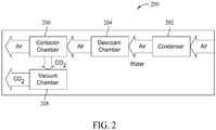
- FIG. 2 is a block diagram of an exemplary apparatus 200 for collecting CO2, such as by the method 100 described above.
- Large amounts of free air are blown through a condenser 202 that removes most of the water from the air.
- the dryer air is then directed through a desiccant chamber 204 that contains a desiccant to remove substantially all of the remaining water in the air.
- the air next enters a contactor chamber 206 which includes a material that adsorbs CO2 from the dry air.
- the adsorbed CO2 is released to a vacuum chamber 208.
- the gaseous CO2 in vacuum chamber 208 is transitioned to a solid in vacuum chamber 208.
- Condenser 202 and desiccant chamber 204 remove substantially all of the water contained in the air to produce dry air for use in the remainder of the process of collecting CO2.
- the water removed from the air is collected as a byproduct of the process.
- the collected water may then be used for any suitable purpose.
- Desiccant chamber 204 contains a desiccant material to remove substantially all of the remaining water from the air that has passed through condenser 202.
- the desiccant material is a molecular sieve material.
- the desiccant material is a molecular sieve material with an alkali metal alumino-silicate structure that has an effective pore opening of three angstroms.
- other desiccant material may be used including, for example, molecular sieve material having different structures and/or effective pore sizes. Any desiccant material suitable to remove substantially all of the water remaining in the air passed through condenser 202 may be used.
- Contactor chamber 206 includes a material that adsorbs CO2 from the dry air.
- the material is a molecular sieve material.
- the molecular sieve material is a molecular sieve material with a 10 angstrom effective pore opening size.
- the molecular sieve material is a zeolite material.
- the material may be any material suitable for adsorbing CO2 from dry air.
- the adsorbed CO2 is released from the material in contactor chamber 206 by subjecting the material to vacuum.
- contactor chamber 206 is substantially sealed to the flow of air, and vacuum is applied, via vacuum chamber 208, to contactor chamber 206.
- the adsorbed CO2 releases from the material in contactor chamber 206 to vacuum chamber 208.
- the gaseous CO2 is transitioned to a solid.
- the CO2 is transitioned to a solid using a surface within vacuum chamber 208 cooled to a temperature low enough to cause the gaseous CO2 to solidify on the cold surface.
- the vacuum chamber includes a cold finger through which a coolant is passed to reduce the temperature of the external surface of the cold finger, onto which the CO2 solidifies.
- any other suitable technique may be used to solidify the released CO2.
- the solid CO2 within vacuum chamber 208 may be collected by any suitable method of collection.
- the solid CO2 is transitioned back to a gas and extracted for storage and/or transport.
- the solid CO2 is transitioned to a gas by raising the temperature within vacuum chamber 208 until the solid CO2 transitions to gaseous CO2.
- any other suitable method for forcing the solid CO2 to transition to a gas may be utilized.
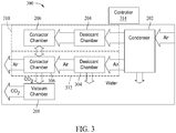
- FIG. 3 is a block diagram of another exemplary apparatus 300 for collecting CO2 according to method 100.
- Apparatus 300 includes condenser 202, desiccant chamber 204, contact chamber 206 and vacuum chamber 208.
- Apparatus 300 also includes a desiccant chamber 304 and a contact chamber 306.
- Desiccant chamber 204 and contact chamber 206 form a first collection assembly 310
- desiccant chamber 304 and contact chamber 306 form a second collection assembly 312.
- Each of the first and second collection assemblies 310 and 312 may be used to extract carbon dioxide from a flow of air from condenser 202 in the manner described above.
- Each of the first and second collection assemblies 310 and 312 may also be described as a collection channel or path.
- a controller 314 controls operation of the apparatus 300 and directs a flow of air from condenser 202 alternately to first collection assembly 310 and second collection assembly 312. For example, after operating first collection assembly 310 for a cycle substantially as discussed above with respect to apparatus 200, controller 314 may close off first collection assembly 310 and open second collection 312. Air from condenser 202 passes into desiccant chamber 304 and is dried as described above with respect to apparatus 200. The dry air then passes to contact chamber 306, where CO2 adsorbs to a material in contact chamber 306. While this is occurring, desiccant chamber 204 is regenerated to remove collected water (not shown in FIG. 3 ) from its last cycle.
- controller 314 When sufficient CO2 has adsorbed in contactor chamber 306, controller 314 seals contactor chamber 306 to the air flow from condenser 202, and connects contactor chambers 206 and 306 in fluid communication with each other. Contactor chamber 206 is at a lower pressure, because of its last cycle, than contactor chamber 306 and the pressures in contactor chambers 206 and 306 equalize. Controller 314 fluidically couples vacuum chamber 208 to contact chamber 306 and the pressure within contact chambers 206 and 306 is reduced to release the CO2 from the material in contact chamber 306.
- the connection between contactor chambers 206 and 306 is closed. Controller 314 may then direct the flow of air from condenser 202 to first collection assembly 310 to begin the extraction process with first collection assembly 310 while second collection assembly finishes the collection process and the desiccant in desiccant chamber 304 is regenerated.
- gaseous CO2 is transitioned to a solid in the manner described above.
- the connection between contactor chamber 306 and vacuum chamber 208 is closed and controller 314 increases the temperature in vacuum chamber 208 to transition the solid CO2 to a gas.
- the CO2 gas is then extracted from vacuum chamber 208 to an external storage facility or pipeline (not shown).
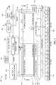
- FIG. 4 is a diagram of another example apparatus, or system, 400 for collecting carbon dioxide according to one or more aspects of this disclosure.
- FIG. 5 is a flow diagram 500 of operation of an apparatus for collecting carbon dioxide, such as apparatus 400.
- Apparatus 400 includes a condenser grid 402, a first collection assembly 410, a second collection assembly 412, and a vacuum chamber 408.
- Each of first and second collection assemblies 410 includes a desiccant chamber 404 and a contactor chamber 406.
- Each of the first and second collection assemblies 410 and 412 may also be described as a collection channel or path.
- Each of first and second collection assemblies 410 and 412 includes a plurality of shutter doors 414 for substantially sealing desiccant chambers 404 and/or contactor chambers 406.
- a system controller 420 controls operation of apparatus 400.
- one collection assembly 410 or 412 is collecting CO2 from free air
- the other collection assembly 412 or 410 is regenerating by releasing the CO2 from contactor chamber 406 and by drying desiccant in desiccant chamber 404 to release its collected water.
- Apparatus 400 includes a plurality of air moving devices 416 positioned to create a flow of atmospheric air through condenser grid 402.
- the air moving devices 416 are fan assemblies.
- air moving devices 416 are industrial grade direct-drive, double-wide, double-inlet fans with backward-inclined fan blades that pull air from outside apparatus 400.
- apparatus 400 includes an air filter assembly 418.
- Air filter assembly 418 includes one or more filters positioned to filter external, atmospheric air pulled into apparatus 400 by air moving devices 416.
- condenser grid 402 includes a condenser or chiller dehydrator that reduces the water content in the air by using a laminar flow heat exchanger that contains cold nitrogen to lower the surface temperature of condenser grid 402 below the dew point.
- the water condenses from the free air on a heat exchanger and is collected as a secondary product.
- condenser grid 402 reduces water content in the air by 90%.
- Controller 420 diverts the output air from the condenser 402 into collection assemblies 410 and 412 on a cyclic basis of collection and regeneration.
- Desiccant chamber 404 in each collection assembly 410 and 412 removes substantially all of the remaining water in the air flowing from condenser 402. Water is captured by the desiccant in desiccant chamber 404 during the collection phase and is released during the regeneration phase of the operation cycle.
- Each desiccant chamber 404 can be independently and cyclically sealed for regeneration. Regeneration of desiccant chambers 404 utilizes residual vacuum and residual heat from other operations, such as vacuum pumps and cryogenic cooling pumps.
- the desiccant material that captures the water is molecular sieve material.
- the molecular sieve material has an alkali metal alumino-silicate structure with an effective pore opening of three angstroms.
- Each contactor chamber 406 contains a material on which CO2 adsorbs from the dry air passing into contactor chamber 406 from desiccant chamber 404.
- the material is a molecular sieve material.
- the material includes a zeolite 13X molecular sieve material with a ten angstrom effective pore opening size.
- the other collector assembly 412 or 410 is in, or has just completed, the regeneration phase of the cycle.
- the contactor chamber 406 of the collector assembly 410 or 412 that is in the regeneration phase is ready to begin its collection phase and is at a low pressure.
- the pressure in both contactor chambers 406 equalizes. In some embodiments, the pressure equalizes to about one-half atmospheric pressure.
- a vacuum pump 422 extracts the chamber air from contactor chamber 406 via vacuum chamber 408 and vents the air outside apparatus 400. Vacuum pump 422 further reduces the pressure in contactor chamber 406 until the pressure is low enough for the adsorbent material to release the CO2 to vacuum chamber 408.
- Vacuum chamber 408 extracts CO2 gas from contactor chamber 406 and captures the CO2 as a solid by using a cold-wall surface.
- vacuum chamber includes a cold finger 424.
- a compressor 426 compresses a coolant that is passed through cold finger 424.
- the coolant includes liquid nitrogen. The liquid nitrogen lowers the temperature of cold finger 424 to below minus 150 degrees Fahrenheit. After the coolant passes through cold finger 424, the coolant is routed through condenser 402 before returning to compressor 426. The surface of cold finger 424 is cooled to a temperature sufficient to cause the CO2 in vacuum chamber 408 to transition from a gaseous state to a solid state.
- vacuum chamber 408 is sealed from contactor chamber 406, the cooling of cold finger 424 is shut off, and heat is added to vacuum chamber 408 until the solid CO2 transitions to a gaseous state.
- heat is added to vacuum chamber 408 using a resistive heater 428 within vacuum chamber 408. In other embodiments other heating devices capable of controlled heating of vacuum chamber 408 may be used.
- the transition from solid to gas increases the pressure in vacuum chamber 408.
- a valve (not shown) to an external compressor 428 is opened and the gaseous CO2 is extracted through external compressor 426 to an external storage facility or pipeline (neither shown).
- Desiccant material in each desiccant chamber 404 is dried during regeneration of the contactor chamber 406 material.
- Desiccant chamber 404 is sealed, using shutters 414, after it is near saturation from the air that has come from condenser 402.
- a valve (not shown) between desiccant chamber 404 and a condenser chamber 430 is opened.
- Vacuum pump 422 pulls on condensing chamber 430, thereby pulling the water out of the desiccant material in desiccant chamber 404 and into condenser chamber 430.
- the valve closes and another valve (not shown) opens to drain the water from condenser chamber 430 and send it to the same storage as the water from condenser 402. As a result, water is collected from both condenser 402 and desiccant chamber 404.
- System controller 420 monitors system operation parameters as well as environmental parameters, such as atmospheric temperature, pressure and humidity. System controller 420 uses this information to control the collection cycle time and the coolant flow through condenser 402. System controller 420 activates actuators to activate gates and valves to operate apparatus 400. In some embodiments, system controller 420 includes a built-in-test (BIT) routine that runs a detailed system operational test at start-up. In some embodiments, system controller 420 continuously monitors system operation and displays current status to a user on a display panel (not shown). In some embodiments, failures of apparatus 400 are alerted by system controller 420 with visual and audio alerts. In some embodiments, system controller 420 may automatically shut down the apparatus 400 partially or entirely upon occurrence of a failure.
- BIT built-in-test
- apparatus 400 is implemented within a single story building having a footprint of about forty feet by fifty feet.
- apparatus 400 includes twenty fans 416 producing a total air flow of about five million cubic feet per minute. This implementation collects over one hundred tons of CO2 per day. For every 100 tons of CO2 collected, this implementation removes about sixty to seventy tons of CO2 from the atmosphere after accounting for the CO2 created by the power plant powering apparatus 400.
- operation of one channel of an apparatus for collecting carbon dioxide begins with fans blowing air into a water condenser.
- Cryogenic coolant flows through the condenser to condense water from the air.
- a gate sends air to an open contactor channel and the air enters a mol sieve desiccant in the open channel.
- the air which is now dry, enters an open contactor chamber where CO2 collected by a 13X molecular sieve.
- the dry air passes through the open contactor chamber. After sufficient carbon dioxide has been collected, the contactor chamber and the desiccant chamber are sealed from the incoming air flow.
- the desiccant chamber is evacuated, the collected water is sent to storage, and the desiccant in the desiccant chamber is dried. Meanwhile, a vacuum pump creates a partial vacuum in the contactor chamber and vents the air extracted from the collector chamber to the outside. The air vent to the outside is closed and the vacuum in the collection chamber causes the collected CO2 to be released from the molecular sieve and collect in a vacuum chamber.
- the CO2 solidifies on a cold finger in the vacuum chamber.
- the cold finger is cooled to about negative one hundred and nine degrees Fahrenheit using cryogenic coolant.
- the cryogenic coolant is circulated through the cold finger and then routed to the condenser described above.
- apparatus 400 When substantially all of the CO2 has been extracted from the contactor chamber, the contactor chamber is sealed from the vacuum chamber and the vacuum chamber is heated. The solid CO2 transitions to a gas and is piped to a storage tank.
- apparatus 400 includes two channels, or paths, that operate in parallel alternating cycles. Thus, when one channel is sealed to extract the collected CO2, the other channel is opened to receive the air blown by fans and collect CO2.
- the systems and methods described herein may be scaled up or down to meet desired CO2 capture. For example, decreasing the airflow of into the system, such as by using fewer or smaller fans, will decrease the amount of CO2 collected each day, but may result in a smaller size system. Similarly, increasing the number of air moving devices, using fans that provide a greater flow of air, etc. can increase the CO2 collected per day, with an increase in system size. Further, more than two collection assemblies may be used. For example, a system can include four collection assemblies cyclically operated in pairs (e.g., two collection assemblies collecting and two collection assemblies regenerating).
- the systems and methods described herein may be implemented at, or near, a location at which the collected CO2 will be used.
- the system may be implemented at the oil field at which the EOR will occur.
- exemplary systems may be implemented located at or near an existing pipeline, thereby reducing transportation and/or pipeline costs.
- exemplary embodiments may provide increased CO2 production over some known methods of CO2 collection. Further, the described embodiments may provide for CO2 collection in environments having atmospheric air with greater water content than the environments in which some known methods are capable of operating. Moreover, the described embodiments provide water as a byproduct of the collection of CO2 and remove more CO2 from the environment than is produced by the embodiments in the process of collecting the CO2. Accordingly, embodiments of the present disclosure may provide affordable, environmentally friendly collection of CO2 from atmospheric air.
Landscapes
- Chemical & Material Sciences (AREA)
- Engineering & Computer Science (AREA)
- Chemical Kinetics & Catalysis (AREA)
- Oil, Petroleum & Natural Gas (AREA)
- Analytical Chemistry (AREA)
- General Chemical & Material Sciences (AREA)
- Organic Chemistry (AREA)
- Environmental & Geological Engineering (AREA)
- Health & Medical Sciences (AREA)
- Biomedical Technology (AREA)
- Inorganic Chemistry (AREA)
- Separation Of Gases By Adsorption (AREA)
- Solid-Sorbent Or Filter-Aiding Compositions (AREA)
- Drying Of Gases (AREA)
- Carbon And Carbon Compounds (AREA)
- Separation By Low-Temperature Treatments (AREA)
- Treating Waste Gases (AREA)
Claims (14)
- Verfahren zum Einfangen von Kohlendioxid (100, 200, 300, 400), wobei das Verfahren umfasst:Entziehen von Wasser aus Atmosphärenluft mithilfe eines Kondensators (102, 202) und eines Trocknungsmittels (404), um trockene Luft zu erzeugen;Adsorbieren von Kohlendioxid aus der trockenen Luft (104) an einem Material in einer Kontaktkammer;und Freisetzen des adsorbierten Kohlendioxids aus der Kontaktkammer;wobei das Verfahren dadurch gekennzeichnet ist, dass das aus der Kontaktkammer freigesetzte adsorbierte Kohlendioxid in eine Vakuumkammer (106) abgegeben wird, indem ein Vakuum an die Vakuumkammer und über die Vakuumkammer an die Kontaktkammer angelegt wird; undwobei das Verfahren ferner umfasst, das freigesetzte Kohlendioxid in der Vakuumkammer (108) von einem Gas in einen Feststoff zu überführen.
- Verfahren nach Anspruch 1, wobei das Entziehen von Wasser aus Atmosphärenluft zum Erzeugen von trockener Luft ein Entziehen von Wasser aus Atmosphärenluft mithilfe einer Zwangsströmung der Atmosphärenluft durch den Kondensator (202) und eine das Trocknungsmittel enthaltende Trocknungskammer (204) umfasst.
- Verfahren nach Anspruch 1, wobei das Adsorbieren von Kohlendioxid umfasst, dass die trockene Luft in einer Kammer (306) durch ein Molekularsiebmaterial geleitet wird.
- Verfahren nach Anspruch 3, wobei das Freisetzen des adsorbierten Kohlendioxids umfasst, dass die Kammer im Wesentlichen abgedichtet ist und innerhalb der Kammer ein Vakuum erzeugt wird, das zum Freisetzen des adsorbierten Kohlendioxids aus dem Molekularsiebmaterial in die Vakuumkammer (208) ausreicht.
- Verfahren nach Anspruch 1, wobei das Überführen des freigesetzten Kohlendioxids ein Kühlen einer Oberfläche (424) innerhalb der Vakuumkammer (408, 208) auf eine Temperatur umfasst, die niedrig genug ist, damit das freigesetzte Kohlendioxid in der Vakuumkammer (106, 408) an der Oberfläche fest wird.
- Verfahren nach Anspruch 5, das ferner ein Überführen des Kohlendioxids in der Vakuumkammer von einem Feststoff in ein Gas zum Auffangen umfasst, indem die Vakuumkammer (408) im Wesentlichen abgedichtet, das Kühlen der Oberfläche beendet und ein Innenraum der Vakuumkammer erwärmt wird.
- Verfahren nach Anspruch 5, wobei das Überführen des freigesetzten Kohlendioxids umfasst, dass sich die innerhalb der Vakuumkammer befindende Oberfläche mit einem Kühlmittel gekühlt wird.
- Verfahren nach Anspruch 7, das ferner ein Leiten des Kühlmittels aus der Vakuumkammer durch den Kondensator umfasst.
- Verfahren nach Anspruch 1, das ferner ein Auffangen des der Atmosphärenluft mithilfe des Kondensators und des Trocknungsmittels entzogenen Wassers umfasst.
- Vorrichtung zum Einfangen von Kohlendioxid, wobei die Vorrichtung aufweist:mehrere Luft bewegende Einrichtungen (416), die zum Erzeugen eines Atmosphärenluftstroms in die Vorrichtung ausgebildet sind;einen Kondensator (202), um dem Atmosphärenluftstrom Wasser zu entziehen;ein Trockenmittel, um dem Atmosphärenluftstrom zum Erzeugen von im Wesentlichen trockener Luft zusätzlich Wasser zu entziehen;eine Kontaktkammer (306) zum Adsorbieren von Kohlendioxid aus der im Wesentlichen trockenen Luft an einem Material in der Kontaktkammer;eine Vakuumkammer (208) zum Evakuieren des adsorbierten Kohlendioxids aus der Kontaktkammer und zum Überführen des evakuierten Kohlendioxids von einem Gas in einen Feststoff, wobei die Kontaktkammer und die Vakuumkammer so angeordnet sind, dass das adsorbierte Kohlendioxid aus der Kontaktkammer zur Vakuumkammer abgegeben wird, wenn an die Vakuumkammer und über die Vakuumkammer an die Kontaktkammer ein Vakuum angelegt wird.
- Vorrichtung nach Anspruch 10, wobei das Material in der Kontaktkammer (306) ein Molekularsiebmaterial umfasst.
- Vorrichtung nach Anspruch 10, wobei die Vakuumkammer einen Kühlfinger (424) aufweist und der Kühlfinger auf eine Temperatur gekühlt ist, die für ein Überführen des evakuierten Kohlendioxids von einem Gas in einen Feststoff ausreicht, wobei sich das feste Kohlendioxid am Kühlfinger ansammelt.
- Vorrichtung nach Anspruch 12, wobei das Kühlen des Kühlfingers mittels eines Hindurchleitens eines Kühlmittels durch den Kühlfinger (424) erfolgt, und wobei das Kühlmittel nach dem Durchströmen des Kühlfingers (424) zu dem Kondensator (202) geleitet wird.
- Vorrichtung nach Anspruch 12, wobei die Vakuumkammer ferner eine Heizung zum Erwärmen der Vakuumkammer auf eine Temperatur umfasst, die für eine Überführung des festen Kohlendioxids in ein Gas ausreicht.
Applications Claiming Priority (1)
| Application Number | Priority Date | Filing Date | Title |
|---|---|---|---|
| US13/220,261 US10118122B2 (en) | 2011-08-29 | 2011-08-29 | CO2 collection methods and systems |
Publications (2)
| Publication Number | Publication Date |
|---|---|
| EP2564914A1 EP2564914A1 (de) | 2013-03-06 |
| EP2564914B1 true EP2564914B1 (de) | 2017-05-31 |
Family
ID=46724247
Family Applications (1)
| Application Number | Title | Priority Date | Filing Date |
|---|---|---|---|
| EP12180636.8A Active EP2564914B1 (de) | 2011-08-29 | 2012-08-16 | Verfahren und Systeme zur Gewinnung von CO2 |
Country Status (6)
| Country | Link |
|---|---|
| US (2) | US10118122B2 (de) |
| EP (1) | EP2564914B1 (de) |
| JP (1) | JP6059916B2 (de) |
| CN (1) | CN102963893B (de) |
| AU (1) | AU2012204024B2 (de) |
| CA (1) | CA2818111C (de) |
Families Citing this family (13)
| Publication number | Priority date | Publication date | Assignee | Title |
|---|---|---|---|---|
| US9205357B2 (en) | 2012-03-29 | 2015-12-08 | The Boeing Company | Carbon dioxide separation system and method |
| US9156703B2 (en) | 2012-03-30 | 2015-10-13 | The Boeing Company | System and method for producing carbon dioxide |
| US9777628B2 (en) | 2012-08-23 | 2017-10-03 | The Boeing Company | System and method for processing greenhouse gases |
| US9103549B2 (en) | 2012-08-23 | 2015-08-11 | The Boeing Company | Dual stream system and method for producing carbon dioxide |
| US9073003B2 (en) | 2012-08-23 | 2015-07-07 | The Boeing Company | System and method for collecting carbon dioxide utilizing dielectric heating |
| US9073001B2 (en) | 2013-02-14 | 2015-07-07 | The Boeing Company | Monolithic contactor and associated system and method for collecting carbon dioxide |
| JP6202371B2 (ja) * | 2013-06-03 | 2017-09-27 | 国立研究開発法人海洋研究開発機構 | 二酸化炭素の再資源化方法 |
| US10066884B2 (en) | 2013-07-25 | 2018-09-04 | Denbury Resources Inc. | Method and apparatus for dampening flow variations and pressurizing carbon dioxide |
| JP7092717B2 (ja) * | 2019-08-08 | 2022-06-28 | フタバ産業株式会社 | 二酸化炭素施用装置 |
| US20230256378A1 (en) * | 2020-07-16 | 2023-08-17 | Qatar Foundation For Education, Science And Community Development | Air conditioning system and method of capturing co2 using the same |
| JP2023553415A (ja) * | 2020-12-09 | 2023-12-21 | アリゾナ・ボード・オブ・リージェンツ・オン・ビハーフ・オブ・アリゾナ・ステイト・ユニバーシティー | 二酸化炭素を効率的に捕捉するためのシステムおよび方法 |
| CA3217481A1 (en) * | 2021-05-07 | 2022-11-10 | Cold Jet, Llc | Method and apparatus for forming solid carbon dioxide |
| US20230314070A1 (en) * | 2022-03-30 | 2023-10-05 | Microsoft Technology Licensing, Llc | Cryogenic removal of carbon dioxide from the atmosphere |
Citations (2)
| Publication number | Priority date | Publication date | Assignee | Title |
|---|---|---|---|---|
| US4551197A (en) * | 1984-07-26 | 1985-11-05 | Guilmette Joseph G | Method and apparatus for the recovery and recycling of condensable gas reactants |
| US7736416B2 (en) * | 2007-02-26 | 2010-06-15 | Hamilton Sundstrand Corporation | Thermally linked molecular sieve beds for CO2 removal |
Family Cites Families (26)
| Publication number | Priority date | Publication date | Assignee | Title |
|---|---|---|---|---|
| US4264340A (en) * | 1979-02-28 | 1981-04-28 | Air Products And Chemicals, Inc. | Vacuum swing adsorption for air fractionation |
| US4249915A (en) | 1979-05-30 | 1981-02-10 | Air Products And Chemicals, Inc. | Removal of water and carbon dioxide from air |
| GB2171927B (en) | 1985-03-04 | 1988-05-25 | Boc Group Plc | Method and apparatus for separating a gaseous mixture |
| JPS62136222A (ja) | 1985-12-10 | 1987-06-19 | Nippon Steel Corp | 混合ガスから特定のガスを吸着分離する方法 |
| US4784672A (en) * | 1987-10-08 | 1988-11-15 | Air Products And Chemicals, Inc. | Regeneration of adsorbents |
| DE4003533A1 (de) | 1989-02-07 | 1990-08-09 | Pero Kg | Verfahren und vorrichtung zur rueckgewinnung von in einem adsorber adsorbierten umweltbelastenden stoffen |
| JPH07108368B2 (ja) * | 1990-11-02 | 1995-11-22 | 住友精化株式会社 | 混合ガス中の水分除去方法 |
| US5229089A (en) * | 1991-11-06 | 1993-07-20 | The Boc Group, Inc. | Recovery of flammable materials from gas streams |
| US5261250A (en) * | 1993-03-09 | 1993-11-16 | Polycold Systems International | Method and apparatus for recovering multicomponent vapor mixtures |
| US5488833A (en) * | 1994-09-26 | 1996-02-06 | Stewart; Jeffrey | Tangential flow cold trap |
| US5518526A (en) * | 1994-10-07 | 1996-05-21 | Praxair Technology, Inc. | Pressure swing adsorption process |
| EP0895484A4 (de) * | 1996-03-26 | 2000-12-06 | Saes Pure Gas Inc | Kryo- und getterpumpenkombination und deren regenerationsverfahren |
| US6332925B1 (en) * | 1996-05-23 | 2001-12-25 | Ebara Corporation | Evacuation system |
| ATE261757T1 (de) * | 1996-12-11 | 2004-04-15 | Sgi Prozess Technik Gmbh | Verfahren zum betrieb einer druckwechselanlage zur gewinnung von sauerstoff aus der luft |
| US6048384A (en) * | 1997-12-09 | 2000-04-11 | Smolarek; James | PSA process and system using simultaneous top and bottom evacuation of absorbent bed |
| US6070431A (en) * | 1999-02-02 | 2000-06-06 | Praxair Technology, Inc. | Distillation system for producing carbon dioxide |
| FR2792210B1 (fr) * | 1999-04-13 | 2001-09-14 | Air Liquide Sante Int | Equipement medical portable d'oxygenotherapie a domicile |
| JP2002013696A (ja) | 2000-06-29 | 2002-01-18 | Tokyo Gas Chemicals Co Ltd | 炭酸ガスの固化精製及び圧力容器への充填方法 |
| US6630012B2 (en) * | 2001-04-30 | 2003-10-07 | Battelle Memorial Institute | Method for thermal swing adsorption and thermally-enhanced pressure swing adsorption |
| US7947239B2 (en) | 2004-05-04 | 2011-05-24 | The Trustees Of Columbia University In The City Of New York | Carbon dioxide capture and mitigation of carbon dioxide emissions |
| US8062408B2 (en) * | 2006-05-08 | 2011-11-22 | The Board Of Trustees Of The University Of Illinois | Integrated vacuum absorption steam cycle gas separation |
| US7695553B2 (en) * | 2006-06-30 | 2010-04-13 | Praxair Technology, Inc. | Twin blowers for gas separation plants |
| US8616294B2 (en) | 2007-05-20 | 2013-12-31 | Pioneer Energy, Inc. | Systems and methods for generating in-situ carbon dioxide driver gas for use in enhanced oil recovery |
| US7650939B2 (en) | 2007-05-20 | 2010-01-26 | Pioneer Energy, Inc. | Portable and modular system for extracting petroleum and generating power |
| US8163070B2 (en) * | 2008-08-01 | 2012-04-24 | Wolfgang Georg Hees | Method and system for extracting carbon dioxide by anti-sublimation at raised pressure |
| US8137435B2 (en) * | 2009-03-31 | 2012-03-20 | L'air Liquide Societe Anonyme Pour L'etude Et L'exploitation Des Procedes Georges Claude | Carbon dioxide recovery from low concentration sources |
-
2011
- 2011-08-29 US US13/220,261 patent/US10118122B2/en active Active
-
2012
- 2012-07-06 AU AU2012204024A patent/AU2012204024B2/en active Active
- 2012-08-16 EP EP12180636.8A patent/EP2564914B1/de active Active
- 2012-08-20 CA CA2818111A patent/CA2818111C/en active Active
- 2012-08-28 CN CN201210310837.7A patent/CN102963893B/zh active Active
- 2012-08-28 JP JP2012187662A patent/JP6059916B2/ja active Active
-
2018
- 2018-10-01 US US16/148,079 patent/US11376543B2/en active Active
Patent Citations (2)
| Publication number | Priority date | Publication date | Assignee | Title |
|---|---|---|---|---|
| US4551197A (en) * | 1984-07-26 | 1985-11-05 | Guilmette Joseph G | Method and apparatus for the recovery and recycling of condensable gas reactants |
| US7736416B2 (en) * | 2007-02-26 | 2010-06-15 | Hamilton Sundstrand Corporation | Thermally linked molecular sieve beds for CO2 removal |
Also Published As
| Publication number | Publication date |
|---|---|
| AU2012204024B2 (en) | 2016-10-27 |
| JP6059916B2 (ja) | 2017-01-11 |
| US20190030478A1 (en) | 2019-01-31 |
| US20130047664A1 (en) | 2013-02-28 |
| AU2012204024A1 (en) | 2013-03-21 |
| EP2564914A1 (de) | 2013-03-06 |
| US10118122B2 (en) | 2018-11-06 |
| US11376543B2 (en) | 2022-07-05 |
| JP2013056329A (ja) | 2013-03-28 |
| CN102963893A (zh) | 2013-03-13 |
| CA2818111C (en) | 2016-11-22 |
| CN102963893B (zh) | 2017-03-01 |
| CA2818111A1 (en) | 2013-02-28 |
Similar Documents
| Publication | Publication Date | Title |
|---|---|---|
| EP2564914B1 (de) | Verfahren und Systeme zur Gewinnung von CO2 | |
| Wang et al. | Experimental evaluation of adsorption technology for CO2 capture from flue gas in an existing coal-fired power plant | |
| CN105032113B (zh) | 基于湿法再生技术捕集烟气中二氧化碳的方法 | |
| CN107300294A (zh) | 一种烟气碳捕集系统的二氧化碳液化装置及方法 | |
| US9375673B2 (en) | CO2 separation unit | |
| EP2644249B1 (de) | System und Verfahren zur Herstellung von Kohlendioxid | |
| JP4033591B2 (ja) | Sf6ガス回収装置 | |
| CN110124443B (zh) | 一种有机废气回收再利用装置及方法 | |
| CN103830991A (zh) | 有机溶剂吸附回收的真空脱附系统及方法 | |
| CN113996616A (zh) | 基于VOCs分离回收技术的涉危化品罐车绿色清洗装置及方法 | |
| WO2015179884A2 (en) | A cyclical system for the regeneration of desiccant | |
| CN207299713U (zh) | 一种烟气碳捕集系统的二氧化碳液化装置 | |
| CN104841245A (zh) | 人造板制造行业用冷凝加吸附式甲醛回收装置及回收方法 | |
| JP6662053B2 (ja) | ガス供給装置及びそれを備えたコンテナ用冷凍装置 | |
| WO2019073866A1 (ja) | Co2分離回収方法及びco2分離回収設備 | |
| JPH09122432A (ja) | 圧力スイング吸着法によるガス分離装置 | |
| CN204656288U (zh) | 人造板制造行业用冷凝加吸附式甲醛回收装置 | |
| US11796514B2 (en) | Apparatuses and methods involving extraction of heavy rare gases | |
| CN203663659U (zh) | 有机溶剂吸附回收的真空脱附系统 | |
| CN203170183U (zh) | 低浓度煤层气变压吸附富集系统 | |
| US20240001286A1 (en) | Direct air capture and concentration of co2 using adsorbents | |
| CN204656278U (zh) | 木质家具行业用常压解析的吸附式甲苯回收装置 | |
| CN204656285U (zh) | 印刷行业用常压解析的吸附式醋酸乙烯回收装置 | |
| Yoshikawa et al. | CO 2 separation unit | |
| KR100559254B1 (ko) | 산소를 고농도로 농축시키는 장치 및 방법 |
Legal Events
| Date | Code | Title | Description |
|---|---|---|---|
| PUAI | Public reference made under article 153(3) epc to a published international application that has entered the european phase |
Free format text: ORIGINAL CODE: 0009012 |
|
| 17P | Request for examination filed |
Effective date: 20120816 |
|
| AK | Designated contracting states |
Kind code of ref document: A1 Designated state(s): AL AT BE BG CH CY CZ DE DK EE ES FI FR GB GR HR HU IE IS IT LI LT LU LV MC MK MT NL NO PL PT RO RS SE SI SK SM TR |
|
| AX | Request for extension of the european patent |
Extension state: BA ME |
|
| 17Q | First examination report despatched |
Effective date: 20151112 |
|
| GRAP | Despatch of communication of intention to grant a patent |
Free format text: ORIGINAL CODE: EPIDOSNIGR1 |
|
| INTG | Intention to grant announced |
Effective date: 20160729 |
|
| GRAJ | Information related to disapproval of communication of intention to grant by the applicant or resumption of examination proceedings by the epo deleted |
Free format text: ORIGINAL CODE: EPIDOSDIGR1 |
|
| GRAP | Despatch of communication of intention to grant a patent |
Free format text: ORIGINAL CODE: EPIDOSNIGR1 |
|
| INTC | Intention to grant announced (deleted) | ||
| INTG | Intention to grant announced |
Effective date: 20161209 |
|
| GRAS | Grant fee paid |
Free format text: ORIGINAL CODE: EPIDOSNIGR3 |
|
| GRAA | (expected) grant |
Free format text: ORIGINAL CODE: 0009210 |
|
| RIC1 | Information provided on ipc code assigned before grant |
Ipc: B01D 53/04 20060101AFI20170420BHEP Ipc: C01B 32/55 20170101ALI20170420BHEP |
|
| AK | Designated contracting states |
Kind code of ref document: B1 Designated state(s): AL AT BE BG CH CY CZ DE DK EE ES FI FR GB GR HR HU IE IS IT LI LT LU LV MC MK MT NL NO PL PT RO RS SE SI SK SM TR |
|
| REG | Reference to a national code |
Ref country code: CH Ref legal event code: EP Ref country code: GB Ref legal event code: FG4D |
|
| REG | Reference to a national code |
Ref country code: AT Ref legal event code: REF Ref document number: 896920 Country of ref document: AT Kind code of ref document: T Effective date: 20170615 |
|
| REG | Reference to a national code |
Ref country code: IE Ref legal event code: FG4D |
|
| REG | Reference to a national code |
Ref country code: DE Ref legal event code: R096 Ref document number: 602012032902 Country of ref document: DE |
|
| REG | Reference to a national code |
Ref country code: FR Ref legal event code: PLFP Year of fee payment: 6 |
|
| REG | Reference to a national code |
Ref country code: NL Ref legal event code: MP Effective date: 20170531 |
|
| REG | Reference to a national code |
Ref country code: LT Ref legal event code: MG4D |
|
| REG | Reference to a national code |
Ref country code: AT Ref legal event code: MK05 Ref document number: 896920 Country of ref document: AT Kind code of ref document: T Effective date: 20170531 |
|
| PG25 | Lapsed in a contracting state [announced via postgrant information from national office to epo] |
Ref country code: GR Free format text: LAPSE BECAUSE OF FAILURE TO SUBMIT A TRANSLATION OF THE DESCRIPTION OR TO PAY THE FEE WITHIN THE PRESCRIBED TIME-LIMIT Effective date: 20170901 Ref country code: FI Free format text: LAPSE BECAUSE OF FAILURE TO SUBMIT A TRANSLATION OF THE DESCRIPTION OR TO PAY THE FEE WITHIN THE PRESCRIBED TIME-LIMIT Effective date: 20170531 Ref country code: AT Free format text: LAPSE BECAUSE OF FAILURE TO SUBMIT A TRANSLATION OF THE DESCRIPTION OR TO PAY THE FEE WITHIN THE PRESCRIBED TIME-LIMIT Effective date: 20170531 Ref country code: HR Free format text: LAPSE BECAUSE OF FAILURE TO SUBMIT A TRANSLATION OF THE DESCRIPTION OR TO PAY THE FEE WITHIN THE PRESCRIBED TIME-LIMIT Effective date: 20170531 Ref country code: NO Free format text: LAPSE BECAUSE OF FAILURE TO SUBMIT A TRANSLATION OF THE DESCRIPTION OR TO PAY THE FEE WITHIN THE PRESCRIBED TIME-LIMIT Effective date: 20170831 Ref country code: ES Free format text: LAPSE BECAUSE OF FAILURE TO SUBMIT A TRANSLATION OF THE DESCRIPTION OR TO PAY THE FEE WITHIN THE PRESCRIBED TIME-LIMIT Effective date: 20170531 Ref country code: LT Free format text: LAPSE BECAUSE OF FAILURE TO SUBMIT A TRANSLATION OF THE DESCRIPTION OR TO PAY THE FEE WITHIN THE PRESCRIBED TIME-LIMIT Effective date: 20170531 |
|
| PG25 | Lapsed in a contracting state [announced via postgrant information from national office to epo] |
Ref country code: SE Free format text: LAPSE BECAUSE OF FAILURE TO SUBMIT A TRANSLATION OF THE DESCRIPTION OR TO PAY THE FEE WITHIN THE PRESCRIBED TIME-LIMIT Effective date: 20170531 Ref country code: IS Free format text: LAPSE BECAUSE OF FAILURE TO SUBMIT A TRANSLATION OF THE DESCRIPTION OR TO PAY THE FEE WITHIN THE PRESCRIBED TIME-LIMIT Effective date: 20170930 Ref country code: NL Free format text: LAPSE BECAUSE OF FAILURE TO SUBMIT A TRANSLATION OF THE DESCRIPTION OR TO PAY THE FEE WITHIN THE PRESCRIBED TIME-LIMIT Effective date: 20170531 Ref country code: LV Free format text: LAPSE BECAUSE OF FAILURE TO SUBMIT A TRANSLATION OF THE DESCRIPTION OR TO PAY THE FEE WITHIN THE PRESCRIBED TIME-LIMIT Effective date: 20170531 Ref country code: RS Free format text: LAPSE BECAUSE OF FAILURE TO SUBMIT A TRANSLATION OF THE DESCRIPTION OR TO PAY THE FEE WITHIN THE PRESCRIBED TIME-LIMIT Effective date: 20170531 Ref country code: BG Free format text: LAPSE BECAUSE OF FAILURE TO SUBMIT A TRANSLATION OF THE DESCRIPTION OR TO PAY THE FEE WITHIN THE PRESCRIBED TIME-LIMIT Effective date: 20170831 |
|
| PG25 | Lapsed in a contracting state [announced via postgrant information from national office to epo] |
Ref country code: RO Free format text: LAPSE BECAUSE OF FAILURE TO SUBMIT A TRANSLATION OF THE DESCRIPTION OR TO PAY THE FEE WITHIN THE PRESCRIBED TIME-LIMIT Effective date: 20170531 Ref country code: EE Free format text: LAPSE BECAUSE OF FAILURE TO SUBMIT A TRANSLATION OF THE DESCRIPTION OR TO PAY THE FEE WITHIN THE PRESCRIBED TIME-LIMIT Effective date: 20170531 Ref country code: CZ Free format text: LAPSE BECAUSE OF FAILURE TO SUBMIT A TRANSLATION OF THE DESCRIPTION OR TO PAY THE FEE WITHIN THE PRESCRIBED TIME-LIMIT Effective date: 20170531 Ref country code: DK Free format text: LAPSE BECAUSE OF FAILURE TO SUBMIT A TRANSLATION OF THE DESCRIPTION OR TO PAY THE FEE WITHIN THE PRESCRIBED TIME-LIMIT Effective date: 20170531 Ref country code: SK Free format text: LAPSE BECAUSE OF FAILURE TO SUBMIT A TRANSLATION OF THE DESCRIPTION OR TO PAY THE FEE WITHIN THE PRESCRIBED TIME-LIMIT Effective date: 20170531 |
|
| PG25 | Lapsed in a contracting state [announced via postgrant information from national office to epo] |
Ref country code: PL Free format text: LAPSE BECAUSE OF FAILURE TO SUBMIT A TRANSLATION OF THE DESCRIPTION OR TO PAY THE FEE WITHIN THE PRESCRIBED TIME-LIMIT Effective date: 20170531 Ref country code: IT Free format text: LAPSE BECAUSE OF FAILURE TO SUBMIT A TRANSLATION OF THE DESCRIPTION OR TO PAY THE FEE WITHIN THE PRESCRIBED TIME-LIMIT Effective date: 20170531 Ref country code: SM Free format text: LAPSE BECAUSE OF FAILURE TO SUBMIT A TRANSLATION OF THE DESCRIPTION OR TO PAY THE FEE WITHIN THE PRESCRIBED TIME-LIMIT Effective date: 20170531 |
|
| REG | Reference to a national code |
Ref country code: DE Ref legal event code: R097 Ref document number: 602012032902 Country of ref document: DE |
|
| REG | Reference to a national code |
Ref country code: CH Ref legal event code: PL |
|
| PG25 | Lapsed in a contracting state [announced via postgrant information from national office to epo] |
Ref country code: MC Free format text: LAPSE BECAUSE OF FAILURE TO SUBMIT A TRANSLATION OF THE DESCRIPTION OR TO PAY THE FEE WITHIN THE PRESCRIBED TIME-LIMIT Effective date: 20170531 |
|
| PLBE | No opposition filed within time limit |
Free format text: ORIGINAL CODE: 0009261 |
|
| STAA | Information on the status of an ep patent application or granted ep patent |
Free format text: STATUS: NO OPPOSITION FILED WITHIN TIME LIMIT |
|
| PG25 | Lapsed in a contracting state [announced via postgrant information from national office to epo] |
Ref country code: LI Free format text: LAPSE BECAUSE OF NON-PAYMENT OF DUE FEES Effective date: 20170831 Ref country code: CH Free format text: LAPSE BECAUSE OF NON-PAYMENT OF DUE FEES Effective date: 20170831 |
|
| 26N | No opposition filed |
Effective date: 20180301 |
|
| REG | Reference to a national code |
Ref country code: IE Ref legal event code: MM4A |
|
| PG25 | Lapsed in a contracting state [announced via postgrant information from national office to epo] |
Ref country code: SI Free format text: LAPSE BECAUSE OF FAILURE TO SUBMIT A TRANSLATION OF THE DESCRIPTION OR TO PAY THE FEE WITHIN THE PRESCRIBED TIME-LIMIT Effective date: 20170531 |
|
| REG | Reference to a national code |
Ref country code: BE Ref legal event code: MM Effective date: 20170831 |
|
| PG25 | Lapsed in a contracting state [announced via postgrant information from national office to epo] |
Ref country code: LU Free format text: LAPSE BECAUSE OF NON-PAYMENT OF DUE FEES Effective date: 20170816 |
|
| PG25 | Lapsed in a contracting state [announced via postgrant information from national office to epo] |
Ref country code: IE Free format text: LAPSE BECAUSE OF NON-PAYMENT OF DUE FEES Effective date: 20170816 |
|
| REG | Reference to a national code |
Ref country code: FR Ref legal event code: PLFP Year of fee payment: 7 |
|
| PG25 | Lapsed in a contracting state [announced via postgrant information from national office to epo] |
Ref country code: BE Free format text: LAPSE BECAUSE OF NON-PAYMENT OF DUE FEES Effective date: 20170831 |
|
| PG25 | Lapsed in a contracting state [announced via postgrant information from national office to epo] |
Ref country code: MT Free format text: LAPSE BECAUSE OF NON-PAYMENT OF DUE FEES Effective date: 20170816 |
|
| PG25 | Lapsed in a contracting state [announced via postgrant information from national office to epo] |
Ref country code: HU Free format text: LAPSE BECAUSE OF FAILURE TO SUBMIT A TRANSLATION OF THE DESCRIPTION OR TO PAY THE FEE WITHIN THE PRESCRIBED TIME-LIMIT; INVALID AB INITIO Effective date: 20120816 |
|
| PG25 | Lapsed in a contracting state [announced via postgrant information from national office to epo] |
Ref country code: CY Free format text: LAPSE BECAUSE OF NON-PAYMENT OF DUE FEES Effective date: 20170531 |
|
| PG25 | Lapsed in a contracting state [announced via postgrant information from national office to epo] |
Ref country code: MK Free format text: LAPSE BECAUSE OF FAILURE TO SUBMIT A TRANSLATION OF THE DESCRIPTION OR TO PAY THE FEE WITHIN THE PRESCRIBED TIME-LIMIT Effective date: 20170531 |
|
| REG | Reference to a national code |
Ref country code: DE Ref legal event code: R082 Ref document number: 602012032902 Country of ref document: DE Representative=s name: MAIER, LL.M., MICHAEL C., DE Ref country code: DE Ref legal event code: R082 Ref document number: 602012032902 Country of ref document: DE Representative=s name: BOULT WADE TENNANT LLP, DE |
|
| REG | Reference to a national code |
Ref country code: DE Ref legal event code: R082 Ref document number: 602012032902 Country of ref document: DE Representative=s name: BOULT WADE TENNANT LLP, DE |
|
| PG25 | Lapsed in a contracting state [announced via postgrant information from national office to epo] |
Ref country code: TR Free format text: LAPSE BECAUSE OF FAILURE TO SUBMIT A TRANSLATION OF THE DESCRIPTION OR TO PAY THE FEE WITHIN THE PRESCRIBED TIME-LIMIT Effective date: 20170531 |
|
| PG25 | Lapsed in a contracting state [announced via postgrant information from national office to epo] |
Ref country code: PT Free format text: LAPSE BECAUSE OF FAILURE TO SUBMIT A TRANSLATION OF THE DESCRIPTION OR TO PAY THE FEE WITHIN THE PRESCRIBED TIME-LIMIT Effective date: 20170531 |
|
| PG25 | Lapsed in a contracting state [announced via postgrant information from national office to epo] |
Ref country code: AL Free format text: LAPSE BECAUSE OF FAILURE TO SUBMIT A TRANSLATION OF THE DESCRIPTION OR TO PAY THE FEE WITHIN THE PRESCRIBED TIME-LIMIT Effective date: 20170531 |
|
| P01 | Opt-out of the competence of the unified patent court (upc) registered |
Effective date: 20230516 |
|
| PGFP | Annual fee paid to national office [announced via postgrant information from national office to epo] |
Ref country code: GB Payment date: 20230828 Year of fee payment: 12 |
|
| PGFP | Annual fee paid to national office [announced via postgrant information from national office to epo] |
Ref country code: FR Payment date: 20230825 Year of fee payment: 12 Ref country code: DE Payment date: 20230829 Year of fee payment: 12 |