EP2564883B1 - Pulsateur électro-pneumatique - Google Patents
Pulsateur électro-pneumatique Download PDFInfo
- Publication number
- EP2564883B1 EP2564883B1 EP11179516.7A EP11179516A EP2564883B1 EP 2564883 B1 EP2564883 B1 EP 2564883B1 EP 11179516 A EP11179516 A EP 11179516A EP 2564883 B1 EP2564883 B1 EP 2564883B1
- Authority
- EP
- European Patent Office
- Prior art keywords
- pneumatic
- valves
- regulating
- linear motor
- pulsator
- Prior art date
- Legal status (The legal status is an assumption and is not a legal conclusion. Google has not performed a legal analysis and makes no representation as to the accuracy of the status listed.)
- Not-in-force
Links
Images

Classifications
-
- A—HUMAN NECESSITIES
- A61—MEDICAL OR VETERINARY SCIENCE; HYGIENE
- A61M—DEVICES FOR INTRODUCING MEDIA INTO, OR ONTO, THE BODY; DEVICES FOR TRANSDUCING BODY MEDIA OR FOR TAKING MEDIA FROM THE BODY; DEVICES FOR PRODUCING OR ENDING SLEEP OR STUPOR
- A61M60/00—Blood pumps; Devices for mechanical circulatory actuation; Balloon pumps for circulatory assistance
- A61M60/40—Details relating to driving
- A61M60/424—Details relating to driving for positive displacement blood pumps
- A61M60/427—Details relating to driving for positive displacement blood pumps the force acting on the blood contacting member being hydraulic or pneumatic
-
- A—HUMAN NECESSITIES
- A61—MEDICAL OR VETERINARY SCIENCE; HYGIENE
- A61M—DEVICES FOR INTRODUCING MEDIA INTO, OR ONTO, THE BODY; DEVICES FOR TRANSDUCING BODY MEDIA OR FOR TAKING MEDIA FROM THE BODY; DEVICES FOR PRODUCING OR ENDING SLEEP OR STUPOR
- A61M60/00—Blood pumps; Devices for mechanical circulatory actuation; Balloon pumps for circulatory assistance
- A61M60/10—Location thereof with respect to the patient's body
- A61M60/122—Implantable pumps or pumping devices, i.e. the blood being pumped inside the patient's body
- A61M60/165—Implantable pumps or pumping devices, i.e. the blood being pumped inside the patient's body implantable in, on, or around the heart
- A61M60/178—Implantable pumps or pumping devices, i.e. the blood being pumped inside the patient's body implantable in, on, or around the heart drawing blood from a ventricle and returning the blood to the arterial system via a cannula external to the ventricle, e.g. left or right ventricular assist devices
-
- A—HUMAN NECESSITIES
- A61—MEDICAL OR VETERINARY SCIENCE; HYGIENE
- A61M—DEVICES FOR INTRODUCING MEDIA INTO, OR ONTO, THE BODY; DEVICES FOR TRANSDUCING BODY MEDIA OR FOR TAKING MEDIA FROM THE BODY; DEVICES FOR PRODUCING OR ENDING SLEEP OR STUPOR
- A61M60/00—Blood pumps; Devices for mechanical circulatory actuation; Balloon pumps for circulatory assistance
- A61M60/20—Type thereof
- A61M60/247—Positive displacement blood pumps
- A61M60/253—Positive displacement blood pumps including a displacement member directly acting on the blood
- A61M60/268—Positive displacement blood pumps including a displacement member directly acting on the blood the displacement member being flexible, e.g. membranes, diaphragms or bladders
-
- A—HUMAN NECESSITIES
- A61—MEDICAL OR VETERINARY SCIENCE; HYGIENE
- A61M—DEVICES FOR INTRODUCING MEDIA INTO, OR ONTO, THE BODY; DEVICES FOR TRANSDUCING BODY MEDIA OR FOR TAKING MEDIA FROM THE BODY; DEVICES FOR PRODUCING OR ENDING SLEEP OR STUPOR
- A61M60/00—Blood pumps; Devices for mechanical circulatory actuation; Balloon pumps for circulatory assistance
- A61M60/40—Details relating to driving
- A61M60/424—Details relating to driving for positive displacement blood pumps
- A61M60/427—Details relating to driving for positive displacement blood pumps the force acting on the blood contacting member being hydraulic or pneumatic
- A61M60/435—Details relating to driving for positive displacement blood pumps the force acting on the blood contacting member being hydraulic or pneumatic with diastole or systole switching by valve means located between the blood pump and the hydraulic or pneumatic energy source
Definitions
- the invention relates to an electro-pneumatic pulsator used in drives of pneumatic ventricular assist devices.
- an electro-pneumatic pulsator according to the Polish patent description with publication number PL 181231 B which has a housing comprising two chambers separated by a group of membranes.
- an electro-pneumatic converter In one of the chambers there is an electro-pneumatic converter, and in the other chamber there is a pneumatic amplifier.
- the pneumatic amplifier chamber has three chambers, two of which have inlet connecting pieces for compressed air, and the third mixing chamber located between them has an outlet connecting piece from the mixing chamber for transmitting a pneumatic wave to the ventricular assist device.
- the electro-pneumatic converter converts the transmitted electrical energy into alternate motion of a group of membranes, and said alternate motion of a group of membranes with the compressed air supplied by means of the two inlet connecting pieces results in activating the valves and transmitting the pneumatic wave through the outlet connecting piece of the mixing chamber.
- artificial heart drive according to the Polish utility model with publication number PL 65284 Y , which has a gas divider with a chamber and two dividing channels.
- a linear motor equipped with a single-acting piston.
- the pistons of said linear motors divide gas by inlets to pumping units of the artificial heart.
- US2009/099498 discloses a cardiopulmonary bypass system utilizing membrane-based reciprocating positive displacement blood pumps ("pod pumps").
- the pod pumps are constructed to provide reduced shear forces on the blood being pumped.
- blood flow through the pod pumps can be controlled by a controller using information from pressure sensors in the control chamber of the pod pumps.
- the pod pumps are included on a disposable unit that can be received and held by a receptacle means on a base unit, the base unit also providing pressurized control fluid to the pod pumps on the disposable unit through the receptacle means.
- US 5217430 discloses an apparatus for driving a medical appliance.
- the apparatus has a single compressor for generating both the positive and the negative pressures.
- Positive and negative pressure valves for controlling communication with the atmosphere are connected to the outlet and inlet terminals of the compressor and the outlet and inlet terminals of the compressor are also connected to a positive pressure accumulator and a negative pressure accumulator, respectively.
- the apparatus has pressure sensors to sense when the pressures in the accumulators reach a set pressure.
- the apparatus further has a one-way valve in the positive pressure line between the compressor and the valve or in the negative pressure line between the compressor and the valve. The apparatus prohibits the positive and negative pressure valves from being open at the same time.
- an electro-pneumatic pulsator suitable for generating a pneumatic wave for driving pneumatic ventricular assist devices comprising a body with an internal mixing chamber, two inlet connecting pieces suitable for connecting pneumatic power supply and two regulating valves located coaxially, wherein the first regulating valve is located between the mixing chamber and the first inlet pneumatic connecting piece and the second regulating valve is located between the mixing chamber and the second inlet pneumatic connecting piece, and an outlet pneumatic connecting piece from the mixing chamber for transmitting a pneumatic wave to a ventricular assist device, wherein there is a motor for alternate opening of the regulating valves, and the regulating valves are oppositely oriented and each regulating valve is seated in an assigned pneumatic head.
- the invention as claimed differs from the closest prior art in that the motor is a double-acting linear motor arranged between the regulating valves and each of the regulating valves is supported by a spring.
- regulating valves are mushroom valves are located in cone seats of pneumatic heads.
- the pin projects over the frontal surface of the valve mushroom and is a contact element of the mushroom with the piston of the linear motor.
- both of the inlet pneumatic connecting pieces are coaxial to the regulating valves.
- Electro-pneumatic pulsators are actuators used , for example, in pneumatic drives of ventricular assist devices.
- the aim of a pulsator is converting a control signal in the form of an electrical signal into a pressure wave and a pneumatic flow with strictly defined parameters depending on the application.
- the parameters of the pressure wave generated by a pulsator are closely connected with the patient's safety. Lack of control over these parameters may result in ineffectiveness of the assisting process. It may lead to occurrences such as hemolysis, heart failure, etc.
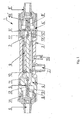
- fig. 1 shows a longitudinal section of an electro-pneumatic pulsator and fig.2 shows a schematic position of the valves and linear motor piston in a resting position.
- An electro-pneumatic pulsator 1 for generating a pneumatic wave for driving pneumatic ventricular assist devices comprises a body 2 with an internal mixing chamber 3. On each side of the body 2 there are pneumatic heads 4 and 4'. Between the head 4 and the mixing chamber 3 there is a regulating valve 5. Between the head 4' and the mixing chamber 3 there is a regulating valve 5'. On the other side the head 4 is equipped with an inlet pneumatic connecting piece 6. The head 4' on the other side is equipped with an inlet connecting piece 6'. The inlet connecting pieces 6 and 6' are used for connecting pneumatic supply and are advantageously located coaxially to the regulating valves 5, 5'.
- the mixing chamber 3 comprises an outlet pneumatic connecting piece 7 for transmitting a pneumatic wave to a ventricular assist device.
- the regulating valves 5 and 5' are located coaxially and are oppositely oriented and each regulating valve 5, 5' located in the assigned pneumatic head 4, 4' is supported by a spring 8, 8' which springs 8, 8' close the regulating valve 5, 5' in a resting position.
- the acting force of the springs, in particular springs 8, 8' of valves 5, 5' is adjustable.
- the double-acting linear motor 9 comprises a piston 10 for single-directional, double-sided work comprising a first end 11 and a second end 11'.
- the linear motor 9 is mounted on the body 2 by mounting means, for example screws.
- Electrical wiring not displayed in the drawing is connected to the motor 9, for example by means of an electrical connector not displayed in the drawing, located in the body 2 of the pulsator 1.
- the ends 11, 11' of the piston 10 may comprise sockets with cooperating elements of the valves 5, 5'.
- the regulating valves 5, 5' may be mushroom valves located in cone seats of the pneumatic heads 4, 4'. Each of said mushrooms 12, 12' of the valves 5, 5' is guided on a pin 13, 13' located in a barrel 14, 14' located in the axis of said mushroom 12, 12'.
- the pins 13, 13' project over the frontal surface of the mushroom 12, 12' and are a contact point of said mushroom with ends 11, 11' of the piston 10 of the linear motor 9, for example with the sockets 16, 16' located on ends 11, 11' of the piston 10.
- the body 2 of the pulsator 1 after closing the inlet pneumatic connecting pieces 6, 6' and the outlet connecting piece 7 is hermetically tight.
- the body 2 of the pulsator 1 may be optionally equipped with a connecting piece 15 for measuring pressure inside the mixing chamber 3.
- the linear motor 9 is located in the body 2 of the pulsator 1 between two mushroom valves 5,5'. In the resting position the valves 5, 5' are closed and the piston 10 of the motor 9 is in "zero" point, in equilibrium between the two valves 5, 5'. The movement of the piston 10 will result in opening of one of the valves.
- the degree of opening of each of the valves determines the flow field and is a function of the distance between the mushroom and the socket.
- the use of a linear motor allows to precisely control time and degree of opening of the valve. Owing to the use of separable fastening between the mushroom and the motor piston, the valves open alternately, which means that when the mushroom of the first valve is open, the mushroom of the second valve remains closed.
- the mixing chamber is the volume between the two valves, to which air may be introduced by the valve of the first head or the valve of the second head.
- the pulsator due to its hermeticity, may also be used in both closed and open pneumatic systems.
Claims (6)
- Le pulsateur électropneumatique (1), formant une onde pneumatique pour entraîner les chambres pneumatiques d'assistance cardiaque, comprenant un corps (2) avec une chambre de mélange interne (3), deux connecteurs d'entrée (6, 6') pneumatiques reliant la source d'alimentation pneumatique et deux soupapes régulatrices (5, 5') disposées coaxialement l'une par rapport à l'autre, la première soupape régulatrice (5) étant située entre la chambre de mélange (3) et le premier connecteur d'entrée (6) pneumatique, et la seconde soupape régulatrice (5) étant située entre la chambre de mélange (3) et le second connecteur d'entrée (6') pneumatique, ainsi qu'un connecteur de sortie (7) pneumatique de la chambre de mélange (3) pour amener l'onde pneumatique à la chambre d'assistance cardiaque, où entre lesdites soupapes régulatrices (5, 5') est localisé un moteur (9) ouvrant alternativement les soupapes régulatrices (5, 5'), lesdites soupapes régulatrices (5, 5') étant orientées de manière opposée et chaque soupape régulatrice (5, 5') étant située dans une tête pneumatique associée (4, 4'), caractérisé en ce que ce que le moteur (9) est un moteur linéaire à double effet, disposé entre les soupapes régulatrices (5, 5') et chaque soupape régulatrice (5, 5') est supportée par un élément à ressort (8, 8').
- Le pulsateur selon la revendication 1, caractérisé en ce que les soupapes régulatrices (5, 5') sont réalisées sous forme de soupapes en champignon incorporées dans les fentes coniques de têtes pneumatiques (4,4').
- Le pulsateur selon les revendications 1 ou 2, caractérisé en ce que chaque champignon (12, 12') des soupapes (5, 5') est guidé sur une épingle (13, 13') située dans un manchon (14, 4') localisé dans l'axe du champignon (12; 12').
- Le pulsateur selon la revendication 3, caractérisé en ce que l'épingle (13, 13') fait saillie au-dessus de la surface frontale du champignon (12, 12') de la soupape (5, 5') et constitue un élément de contact du champignon (12, 12') avec le piston (10) du moteur linéaire (9).
- Le pulsateur selon l'une des revendications 1 à 4, caiactérisé en ce que les deux connecteurs d'entrée pneumatiques (6, 6') sont disposés coaxialement par rapport aux soupapes régulatrice (5, 5').
- Le pulsateur selon l'une des revendications 1 à 5, caractérisé en ce que dans la position de repos, où les deux soupapes régulatrices (5, 5') sont fermés, la somme des distances (A) entre les éléments coopérants de la première soupape régulatrice (5) et la première extrémité qui lui est associée (11) du piston (10) du moteur linéaire (9), et des distances entre les éléments coopérants de la seconde soupape régulatrice (5') et la seconde extrémité qui lui est associée (11') du piston (10) du moteur linéaire (9) est inférieure au saut minimum du moteur linéaire (9).
Priority Applications (2)
| Application Number | Priority Date | Filing Date | Title |
|---|---|---|---|
| PL11179516T PL2564883T3 (pl) | 2011-08-31 | 2011-08-31 | Pulsator elektropneumatyczny |
| EP11179516.7A EP2564883B1 (fr) | 2011-08-31 | 2011-08-31 | Pulsateur électro-pneumatique |
Applications Claiming Priority (1)
| Application Number | Priority Date | Filing Date | Title |
|---|---|---|---|
| EP11179516.7A EP2564883B1 (fr) | 2011-08-31 | 2011-08-31 | Pulsateur électro-pneumatique |
Publications (2)
| Publication Number | Publication Date |
|---|---|
| EP2564883A1 EP2564883A1 (fr) | 2013-03-06 |
| EP2564883B1 true EP2564883B1 (fr) | 2014-05-07 |
Family
ID=44946950
Family Applications (1)
| Application Number | Title | Priority Date | Filing Date |
|---|---|---|---|
| EP11179516.7A Not-in-force EP2564883B1 (fr) | 2011-08-31 | 2011-08-31 | Pulsateur électro-pneumatique |
Country Status (2)
| Country | Link |
|---|---|
| EP (1) | EP2564883B1 (fr) |
| PL (1) | PL2564883T3 (fr) |
Families Citing this family (1)
| Publication number | Priority date | Publication date | Assignee | Title |
|---|---|---|---|---|
| EP3473279B1 (fr) * | 2017-10-20 | 2020-07-08 | PulseCath B.V. | Système de pompe à cathéter |
Family Cites Families (6)
| Publication number | Priority date | Publication date | Assignee | Title |
|---|---|---|---|---|
| US5217430A (en) * | 1988-03-30 | 1993-06-08 | Aisin Seiki K.K. | Apparatus for driving a medical appliance |
| US5300111A (en) * | 1992-02-03 | 1994-04-05 | Pyxis, Inc. | Total artificial heart |
| US5759148A (en) * | 1995-10-18 | 1998-06-02 | Sipin; Anatole J. | Controlled pneumatic driving system |
| PL181231B1 (pl) | 1996-10-11 | 2001-06-29 | Fundacja Rozwoju Kardiochirurg | Pulsator elektropneumatyczn |
| EP2246080B1 (fr) * | 2007-10-12 | 2016-02-10 | DEKA Products Limited Partnership | Système de circulation sanguine extracorporel |
| PL65284Y1 (pl) | 2008-10-06 | 2011-02-28 | Bronisław Kosowski | Układ napędowy sztucznego serca |
-
2011
- 2011-08-31 EP EP11179516.7A patent/EP2564883B1/fr not_active Not-in-force
- 2011-08-31 PL PL11179516T patent/PL2564883T3/pl unknown
Also Published As
| Publication number | Publication date |
|---|---|
| EP2564883A1 (fr) | 2013-03-06 |
| PL2564883T3 (pl) | 2014-09-30 |
Similar Documents
| Publication | Publication Date | Title |
|---|---|---|
| US11867165B2 (en) | Drive system for a positive displacement pump | |
| KR101864806B1 (ko) | 다이어프램 진공 펌프 | |
| US5415532A (en) | High effieciency balanced oscillating shuttle pump | |
| US8490504B2 (en) | Fatigue evaluation of prostheses by radial excitation of tubular structures | |
| JP2019177479A (ja) | 自給式ロボットグリッパシステム | |
| US20040261608A1 (en) | Multi-valve fluid operated cylinder positioning system | |
| JP5819982B2 (ja) | 液圧式硝子体切除プローブ | |
| EP2712599A1 (fr) | Pompage de dispositif de compression | |
| RU2013108847A (ru) | Поршневой насос с регулируемым буфером | |
| US9752566B2 (en) | Air mass control for diaphragm pumps | |
| EP2564883B1 (fr) | Pulsateur électro-pneumatique | |
| CA2834708A1 (fr) | Gel de couplage pour systemes de distribution de fluide electrocinetique | |
| CA2762200A1 (fr) | Mecanisme d'actionnement pour cur artificiel entraine par pneumatique | |
| EP2003056B1 (fr) | Système d'actionnement, hélicoptère l'utilisant et procédé de contrôle correspondant | |
| EP2538081A1 (fr) | Système, procédé et dispositif pour machine | |
| CN109185555B (zh) | 一种基于3d打印的软体机器人微型电动气阀 | |
| US10077763B2 (en) | Air operated pump |
Legal Events
| Date | Code | Title | Description |
|---|---|---|---|
| PUAI | Public reference made under article 153(3) epc to a published international application that has entered the european phase |
Free format text: ORIGINAL CODE: 0009012 |
|
| AK | Designated contracting states |
Kind code of ref document: A1 Designated state(s): AL AT BE BG CH CY CZ DE DK EE ES FI FR GB GR HR HU IE IS IT LI LT LU LV MC MK MT NL NO PL PT RO RS SE SI SK SM TR |
|
| AX | Request for extension of the european patent |
Extension state: BA ME |
|
| 17P | Request for examination filed |
Effective date: 20130827 |
|
| RBV | Designated contracting states (corrected) |
Designated state(s): AL AT BE BG CH CY CZ DE DK EE ES FI FR GB GR HR HU IE IS IT LI LT LU LV MC MK MT NL NO PL PT RO RS SE SI SK SM TR |
|
| GRAP | Despatch of communication of intention to grant a patent |
Free format text: ORIGINAL CODE: EPIDOSNIGR1 |
|
| INTG | Intention to grant announced |
Effective date: 20131219 |
|
| GRAS | Grant fee paid |
Free format text: ORIGINAL CODE: EPIDOSNIGR3 |
|
| GRAA | (expected) grant |
Free format text: ORIGINAL CODE: 0009210 |
|
| AK | Designated contracting states |
Kind code of ref document: B1 Designated state(s): AL AT BE BG CH CY CZ DE DK EE ES FI FR GB GR HR HU IE IS IT LI LT LU LV MC MK MT NL NO PL PT RO RS SE SI SK SM TR |
|
| REG | Reference to a national code |
Ref country code: GB Ref legal event code: FG4D |
|
| REG | Reference to a national code |
Ref country code: AT Ref legal event code: REF Ref document number: 666104 Country of ref document: AT Kind code of ref document: T Effective date: 20140515 |
|
| REG | Reference to a national code |
Ref country code: IE Ref legal event code: FG4D |
|
| REG | Reference to a national code |
Ref country code: DE Ref legal event code: R096 Ref document number: 602011006723 Country of ref document: DE Effective date: 20140618 |
|
| REG | Reference to a national code |
Ref country code: AT Ref legal event code: MK05 Ref document number: 666104 Country of ref document: AT Kind code of ref document: T Effective date: 20140507 |
|
| REG | Reference to a national code |
Ref country code: PL Ref legal event code: T3 |
|
| REG | Reference to a national code |
Ref country code: NL Ref legal event code: VDEP Effective date: 20140507 |
|
| REG | Reference to a national code |
Ref country code: LT Ref legal event code: MG4D |
|
| PG25 | Lapsed in a contracting state [announced via postgrant information from national office to epo] |
Ref country code: FI Free format text: LAPSE BECAUSE OF FAILURE TO SUBMIT A TRANSLATION OF THE DESCRIPTION OR TO PAY THE FEE WITHIN THE PRESCRIBED TIME-LIMIT Effective date: 20140507 Ref country code: LT Free format text: LAPSE BECAUSE OF FAILURE TO SUBMIT A TRANSLATION OF THE DESCRIPTION OR TO PAY THE FEE WITHIN THE PRESCRIBED TIME-LIMIT Effective date: 20140507 Ref country code: GR Free format text: LAPSE BECAUSE OF FAILURE TO SUBMIT A TRANSLATION OF THE DESCRIPTION OR TO PAY THE FEE WITHIN THE PRESCRIBED TIME-LIMIT Effective date: 20140808 Ref country code: CY Free format text: LAPSE BECAUSE OF FAILURE TO SUBMIT A TRANSLATION OF THE DESCRIPTION OR TO PAY THE FEE WITHIN THE PRESCRIBED TIME-LIMIT Effective date: 20140507 Ref country code: IS Free format text: LAPSE BECAUSE OF FAILURE TO SUBMIT A TRANSLATION OF THE DESCRIPTION OR TO PAY THE FEE WITHIN THE PRESCRIBED TIME-LIMIT Effective date: 20140907 Ref country code: NO Free format text: LAPSE BECAUSE OF FAILURE TO SUBMIT A TRANSLATION OF THE DESCRIPTION OR TO PAY THE FEE WITHIN THE PRESCRIBED TIME-LIMIT Effective date: 20140807 |
|
| PG25 | Lapsed in a contracting state [announced via postgrant information from national office to epo] |
Ref country code: RS Free format text: LAPSE BECAUSE OF FAILURE TO SUBMIT A TRANSLATION OF THE DESCRIPTION OR TO PAY THE FEE WITHIN THE PRESCRIBED TIME-LIMIT Effective date: 20140507 Ref country code: ES Free format text: LAPSE BECAUSE OF FAILURE TO SUBMIT A TRANSLATION OF THE DESCRIPTION OR TO PAY THE FEE WITHIN THE PRESCRIBED TIME-LIMIT Effective date: 20140507 Ref country code: HR Free format text: LAPSE BECAUSE OF FAILURE TO SUBMIT A TRANSLATION OF THE DESCRIPTION OR TO PAY THE FEE WITHIN THE PRESCRIBED TIME-LIMIT Effective date: 20140507 Ref country code: AT Free format text: LAPSE BECAUSE OF FAILURE TO SUBMIT A TRANSLATION OF THE DESCRIPTION OR TO PAY THE FEE WITHIN THE PRESCRIBED TIME-LIMIT Effective date: 20140507 Ref country code: LV Free format text: LAPSE BECAUSE OF FAILURE TO SUBMIT A TRANSLATION OF THE DESCRIPTION OR TO PAY THE FEE WITHIN THE PRESCRIBED TIME-LIMIT Effective date: 20140507 Ref country code: SE Free format text: LAPSE BECAUSE OF FAILURE TO SUBMIT A TRANSLATION OF THE DESCRIPTION OR TO PAY THE FEE WITHIN THE PRESCRIBED TIME-LIMIT Effective date: 20140507 |
|
| PG25 | Lapsed in a contracting state [announced via postgrant information from national office to epo] |
Ref country code: PT Free format text: LAPSE BECAUSE OF FAILURE TO SUBMIT A TRANSLATION OF THE DESCRIPTION OR TO PAY THE FEE WITHIN THE PRESCRIBED TIME-LIMIT Effective date: 20140908 |
|
| PG25 | Lapsed in a contracting state [announced via postgrant information from national office to epo] |
Ref country code: CZ Free format text: LAPSE BECAUSE OF FAILURE TO SUBMIT A TRANSLATION OF THE DESCRIPTION OR TO PAY THE FEE WITHIN THE PRESCRIBED TIME-LIMIT Effective date: 20140507 Ref country code: BE Free format text: LAPSE BECAUSE OF FAILURE TO SUBMIT A TRANSLATION OF THE DESCRIPTION OR TO PAY THE FEE WITHIN THE PRESCRIBED TIME-LIMIT Effective date: 20140507 Ref country code: SK Free format text: LAPSE BECAUSE OF FAILURE TO SUBMIT A TRANSLATION OF THE DESCRIPTION OR TO PAY THE FEE WITHIN THE PRESCRIBED TIME-LIMIT Effective date: 20140507 Ref country code: EE Free format text: LAPSE BECAUSE OF FAILURE TO SUBMIT A TRANSLATION OF THE DESCRIPTION OR TO PAY THE FEE WITHIN THE PRESCRIBED TIME-LIMIT Effective date: 20140507 Ref country code: RO Free format text: LAPSE BECAUSE OF FAILURE TO SUBMIT A TRANSLATION OF THE DESCRIPTION OR TO PAY THE FEE WITHIN THE PRESCRIBED TIME-LIMIT Effective date: 20140507 Ref country code: DK Free format text: LAPSE BECAUSE OF FAILURE TO SUBMIT A TRANSLATION OF THE DESCRIPTION OR TO PAY THE FEE WITHIN THE PRESCRIBED TIME-LIMIT Effective date: 20140507 |
|
| REG | Reference to a national code |
Ref country code: DE Ref legal event code: R097 Ref document number: 602011006723 Country of ref document: DE |
|
| PG25 | Lapsed in a contracting state [announced via postgrant information from national office to epo] |
Ref country code: NL Free format text: LAPSE BECAUSE OF FAILURE TO SUBMIT A TRANSLATION OF THE DESCRIPTION OR TO PAY THE FEE WITHIN THE PRESCRIBED TIME-LIMIT Effective date: 20140507 |
|
| REG | Reference to a national code |
Ref country code: DE Ref legal event code: R119 Ref document number: 602011006723 Country of ref document: DE |
|
| PLBE | No opposition filed within time limit |
Free format text: ORIGINAL CODE: 0009261 |
|
| STAA | Information on the status of an ep patent application or granted ep patent |
Free format text: STATUS: NO OPPOSITION FILED WITHIN TIME LIMIT |
|
| PG25 | Lapsed in a contracting state [announced via postgrant information from national office to epo] |
Ref country code: MC Free format text: LAPSE BECAUSE OF FAILURE TO SUBMIT A TRANSLATION OF THE DESCRIPTION OR TO PAY THE FEE WITHIN THE PRESCRIBED TIME-LIMIT Effective date: 20140507 Ref country code: LU Free format text: LAPSE BECAUSE OF FAILURE TO SUBMIT A TRANSLATION OF THE DESCRIPTION OR TO PAY THE FEE WITHIN THE PRESCRIBED TIME-LIMIT Effective date: 20140831 |
|
| REG | Reference to a national code |
Ref country code: CH Ref legal event code: PL |
|
| 26N | No opposition filed |
Effective date: 20150210 |
|
| PG25 | Lapsed in a contracting state [announced via postgrant information from national office to epo] |
Ref country code: LI Free format text: LAPSE BECAUSE OF NON-PAYMENT OF DUE FEES Effective date: 20140831 Ref country code: IT Free format text: LAPSE BECAUSE OF FAILURE TO SUBMIT A TRANSLATION OF THE DESCRIPTION OR TO PAY THE FEE WITHIN THE PRESCRIBED TIME-LIMIT Effective date: 20140507 Ref country code: BE Free format text: LAPSE BECAUSE OF FAILURE TO SUBMIT A TRANSLATION OF THE DESCRIPTION OR TO PAY THE FEE WITHIN THE PRESCRIBED TIME-LIMIT Effective date: 20140831 Ref country code: CH Free format text: LAPSE BECAUSE OF NON-PAYMENT OF DUE FEES Effective date: 20140831 |
|
| REG | Reference to a national code |
Ref country code: DE Ref legal event code: R119 Ref document number: 602011006723 Country of ref document: DE Effective date: 20150303 |
|
| REG | Reference to a national code |
Ref country code: FR Ref legal event code: ST Effective date: 20150430 |
|
| REG | Reference to a national code |
Ref country code: IE Ref legal event code: MM4A |
|
| PG25 | Lapsed in a contracting state [announced via postgrant information from national office to epo] |
Ref country code: DE Free format text: LAPSE BECAUSE OF NON-PAYMENT OF DUE FEES Effective date: 20150303 Ref country code: SI Free format text: LAPSE BECAUSE OF FAILURE TO SUBMIT A TRANSLATION OF THE DESCRIPTION OR TO PAY THE FEE WITHIN THE PRESCRIBED TIME-LIMIT Effective date: 20140507 |
|
| PG25 | Lapsed in a contracting state [announced via postgrant information from national office to epo] |
Ref country code: IE Free format text: LAPSE BECAUSE OF NON-PAYMENT OF DUE FEES Effective date: 20140831 Ref country code: FR Free format text: LAPSE BECAUSE OF NON-PAYMENT OF DUE FEES Effective date: 20140901 |
|
| GBPC | Gb: european patent ceased through non-payment of renewal fee |
Effective date: 20150831 |
|
| PG25 | Lapsed in a contracting state [announced via postgrant information from national office to epo] |
Ref country code: SM Free format text: LAPSE BECAUSE OF FAILURE TO SUBMIT A TRANSLATION OF THE DESCRIPTION OR TO PAY THE FEE WITHIN THE PRESCRIBED TIME-LIMIT Effective date: 20140507 |
|
| PG25 | Lapsed in a contracting state [announced via postgrant information from national office to epo] |
Ref country code: MT Free format text: LAPSE BECAUSE OF FAILURE TO SUBMIT A TRANSLATION OF THE DESCRIPTION OR TO PAY THE FEE WITHIN THE PRESCRIBED TIME-LIMIT Effective date: 20140507 Ref country code: BG Free format text: LAPSE BECAUSE OF FAILURE TO SUBMIT A TRANSLATION OF THE DESCRIPTION OR TO PAY THE FEE WITHIN THE PRESCRIBED TIME-LIMIT Effective date: 20140507 |
|
| PG25 | Lapsed in a contracting state [announced via postgrant information from national office to epo] |
Ref country code: HU Free format text: LAPSE BECAUSE OF FAILURE TO SUBMIT A TRANSLATION OF THE DESCRIPTION OR TO PAY THE FEE WITHIN THE PRESCRIBED TIME-LIMIT; INVALID AB INITIO Effective date: 20110831 Ref country code: TR Free format text: LAPSE BECAUSE OF FAILURE TO SUBMIT A TRANSLATION OF THE DESCRIPTION OR TO PAY THE FEE WITHIN THE PRESCRIBED TIME-LIMIT Effective date: 20140507 Ref country code: GB Free format text: LAPSE BECAUSE OF NON-PAYMENT OF DUE FEES Effective date: 20150831 |
|
| PG25 | Lapsed in a contracting state [announced via postgrant information from national office to epo] |
Ref country code: MK Free format text: LAPSE BECAUSE OF FAILURE TO SUBMIT A TRANSLATION OF THE DESCRIPTION OR TO PAY THE FEE WITHIN THE PRESCRIBED TIME-LIMIT Effective date: 20140507 |
|
| PG25 | Lapsed in a contracting state [announced via postgrant information from national office to epo] |
Ref country code: AL Free format text: LAPSE BECAUSE OF FAILURE TO SUBMIT A TRANSLATION OF THE DESCRIPTION OR TO PAY THE FEE WITHIN THE PRESCRIBED TIME-LIMIT Effective date: 20140507 |
|
| PGFP | Annual fee paid to national office [announced via postgrant information from national office to epo] |
Ref country code: PL Payment date: 20180828 Year of fee payment: 8 |
|
| PG25 | Lapsed in a contracting state [announced via postgrant information from national office to epo] |
Ref country code: PL Free format text: LAPSE BECAUSE OF NON-PAYMENT OF DUE FEES Effective date: 20190831 |