EP2564449B1 - Battery box for electric or hybrid vehicle and method for mounting said box on the vehicle - Google Patents
Battery box for electric or hybrid vehicle and method for mounting said box on the vehicle Download PDFInfo
- Publication number
- EP2564449B1 EP2564449B1 EP11714577.1A EP11714577A EP2564449B1 EP 2564449 B1 EP2564449 B1 EP 2564449B1 EP 11714577 A EP11714577 A EP 11714577A EP 2564449 B1 EP2564449 B1 EP 2564449B1
- Authority
- EP
- European Patent Office
- Prior art keywords
- battery box
- positioning
- vehicle
- bracket
- battery
- Prior art date
- Legal status (The legal status is an assumption and is not a legal conclusion. Google has not performed a legal analysis and makes no representation as to the accuracy of the status listed.)
- Not-in-force
Links
Images


Classifications
-
- B—PERFORMING OPERATIONS; TRANSPORTING
- B60—VEHICLES IN GENERAL
- B60K—ARRANGEMENT OR MOUNTING OF PROPULSION UNITS OR OF TRANSMISSIONS IN VEHICLES; ARRANGEMENT OR MOUNTING OF PLURAL DIVERSE PRIME-MOVERS IN VEHICLES; AUXILIARY DRIVES FOR VEHICLES; INSTRUMENTATION OR DASHBOARDS FOR VEHICLES; ARRANGEMENTS IN CONNECTION WITH COOLING, AIR INTAKE, GAS EXHAUST OR FUEL SUPPLY OF PROPULSION UNITS IN VEHICLES
- B60K1/00—Arrangement or mounting of electrical propulsion units
- B60K1/04—Arrangement or mounting of electrical propulsion units of the electric storage means for propulsion
-
- B—PERFORMING OPERATIONS; TRANSPORTING
- B23—MACHINE TOOLS; METAL-WORKING NOT OTHERWISE PROVIDED FOR
- B23P—METAL-WORKING NOT OTHERWISE PROVIDED FOR; COMBINED OPERATIONS; UNIVERSAL MACHINE TOOLS
- B23P11/00—Connecting or disconnecting metal parts or objects by metal-working techniques not otherwise provided for
-
- B—PERFORMING OPERATIONS; TRANSPORTING
- B60—VEHICLES IN GENERAL
- B60L—PROPULSION OF ELECTRICALLY-PROPELLED VEHICLES; SUPPLYING ELECTRIC POWER FOR AUXILIARY EQUIPMENT OF ELECTRICALLY-PROPELLED VEHICLES; ELECTRODYNAMIC BRAKE SYSTEMS FOR VEHICLES IN GENERAL; MAGNETIC SUSPENSION OR LEVITATION FOR VEHICLES; MONITORING OPERATING VARIABLES OF ELECTRICALLY-PROPELLED VEHICLES; ELECTRIC SAFETY DEVICES FOR ELECTRICALLY-PROPELLED VEHICLES
- B60L50/00—Electric propulsion with power supplied within the vehicle
- B60L50/50—Electric propulsion with power supplied within the vehicle using propulsion power supplied by batteries or fuel cells
- B60L50/60—Electric propulsion with power supplied within the vehicle using propulsion power supplied by batteries or fuel cells using power supplied by batteries
- B60L50/64—Constructional details of batteries specially adapted for electric vehicles
-
- B—PERFORMING OPERATIONS; TRANSPORTING
- B60—VEHICLES IN GENERAL
- B60L—PROPULSION OF ELECTRICALLY-PROPELLED VEHICLES; SUPPLYING ELECTRIC POWER FOR AUXILIARY EQUIPMENT OF ELECTRICALLY-PROPELLED VEHICLES; ELECTRODYNAMIC BRAKE SYSTEMS FOR VEHICLES IN GENERAL; MAGNETIC SUSPENSION OR LEVITATION FOR VEHICLES; MONITORING OPERATING VARIABLES OF ELECTRICALLY-PROPELLED VEHICLES; ELECTRIC SAFETY DEVICES FOR ELECTRICALLY-PROPELLED VEHICLES
- B60L50/00—Electric propulsion with power supplied within the vehicle
- B60L50/50—Electric propulsion with power supplied within the vehicle using propulsion power supplied by batteries or fuel cells
- B60L50/60—Electric propulsion with power supplied within the vehicle using propulsion power supplied by batteries or fuel cells using power supplied by batteries
- B60L50/66—Arrangements of batteries
-
- B—PERFORMING OPERATIONS; TRANSPORTING
- B60—VEHICLES IN GENERAL
- B60L—PROPULSION OF ELECTRICALLY-PROPELLED VEHICLES; SUPPLYING ELECTRIC POWER FOR AUXILIARY EQUIPMENT OF ELECTRICALLY-PROPELLED VEHICLES; ELECTRODYNAMIC BRAKE SYSTEMS FOR VEHICLES IN GENERAL; MAGNETIC SUSPENSION OR LEVITATION FOR VEHICLES; MONITORING OPERATING VARIABLES OF ELECTRICALLY-PROPELLED VEHICLES; ELECTRIC SAFETY DEVICES FOR ELECTRICALLY-PROPELLED VEHICLES
- B60L53/00—Methods of charging batteries, specially adapted for electric vehicles; Charging stations or on-board charging equipment therefor; Exchange of energy storage elements in electric vehicles
- B60L53/80—Exchanging energy storage elements, e.g. removable batteries
-
- H—ELECTRICITY
- H01—ELECTRIC ELEMENTS
- H01M—PROCESSES OR MEANS, e.g. BATTERIES, FOR THE DIRECT CONVERSION OF CHEMICAL ENERGY INTO ELECTRICAL ENERGY
- H01M50/00—Constructional details or processes of manufacture of the non-active parts of electrochemical cells other than fuel cells, e.g. hybrid cells
- H01M50/20—Mountings; Secondary casings or frames; Racks, modules or packs; Suspension devices; Shock absorbers; Transport or carrying devices; Holders
- H01M50/204—Racks, modules or packs for multiple batteries or multiple cells
-
- H—ELECTRICITY
- H01—ELECTRIC ELEMENTS
- H01M—PROCESSES OR MEANS, e.g. BATTERIES, FOR THE DIRECT CONVERSION OF CHEMICAL ENERGY INTO ELECTRICAL ENERGY
- H01M50/00—Constructional details or processes of manufacture of the non-active parts of electrochemical cells other than fuel cells, e.g. hybrid cells
- H01M50/20—Mountings; Secondary casings or frames; Racks, modules or packs; Suspension devices; Shock absorbers; Transport or carrying devices; Holders
- H01M50/249—Mountings; Secondary casings or frames; Racks, modules or packs; Suspension devices; Shock absorbers; Transport or carrying devices; Holders specially adapted for aircraft or vehicles, e.g. cars or trains
-
- B—PERFORMING OPERATIONS; TRANSPORTING
- B60—VEHICLES IN GENERAL
- B60K—ARRANGEMENT OR MOUNTING OF PROPULSION UNITS OR OF TRANSMISSIONS IN VEHICLES; ARRANGEMENT OR MOUNTING OF PLURAL DIVERSE PRIME-MOVERS IN VEHICLES; AUXILIARY DRIVES FOR VEHICLES; INSTRUMENTATION OR DASHBOARDS FOR VEHICLES; ARRANGEMENTS IN CONNECTION WITH COOLING, AIR INTAKE, GAS EXHAUST OR FUEL SUPPLY OF PROPULSION UNITS IN VEHICLES
- B60K1/00—Arrangement or mounting of electrical propulsion units
- B60K1/04—Arrangement or mounting of electrical propulsion units of the electric storage means for propulsion
- B60K2001/0405—Arrangement or mounting of electrical propulsion units of the electric storage means for propulsion characterised by their position
- B60K2001/0438—Arrangement under the floor
-
- B—PERFORMING OPERATIONS; TRANSPORTING
- B60—VEHICLES IN GENERAL
- B60K—ARRANGEMENT OR MOUNTING OF PROPULSION UNITS OR OF TRANSMISSIONS IN VEHICLES; ARRANGEMENT OR MOUNTING OF PLURAL DIVERSE PRIME-MOVERS IN VEHICLES; AUXILIARY DRIVES FOR VEHICLES; INSTRUMENTATION OR DASHBOARDS FOR VEHICLES; ARRANGEMENTS IN CONNECTION WITH COOLING, AIR INTAKE, GAS EXHAUST OR FUEL SUPPLY OF PROPULSION UNITS IN VEHICLES
- B60K1/00—Arrangement or mounting of electrical propulsion units
- B60K1/04—Arrangement or mounting of electrical propulsion units of the electric storage means for propulsion
- B60K2001/0455—Removal or replacement of the energy storages
- B60K2001/0472—Removal or replacement of the energy storages from below
-
- Y—GENERAL TAGGING OF NEW TECHNOLOGICAL DEVELOPMENTS; GENERAL TAGGING OF CROSS-SECTIONAL TECHNOLOGIES SPANNING OVER SEVERAL SECTIONS OF THE IPC; TECHNICAL SUBJECTS COVERED BY FORMER USPC CROSS-REFERENCE ART COLLECTIONS [XRACs] AND DIGESTS
- Y02—TECHNOLOGIES OR APPLICATIONS FOR MITIGATION OR ADAPTATION AGAINST CLIMATE CHANGE
- Y02E—REDUCTION OF GREENHOUSE GAS [GHG] EMISSIONS, RELATED TO ENERGY GENERATION, TRANSMISSION OR DISTRIBUTION
- Y02E60/00—Enabling technologies; Technologies with a potential or indirect contribution to GHG emissions mitigation
- Y02E60/10—Energy storage using batteries
-
- Y—GENERAL TAGGING OF NEW TECHNOLOGICAL DEVELOPMENTS; GENERAL TAGGING OF CROSS-SECTIONAL TECHNOLOGIES SPANNING OVER SEVERAL SECTIONS OF THE IPC; TECHNICAL SUBJECTS COVERED BY FORMER USPC CROSS-REFERENCE ART COLLECTIONS [XRACs] AND DIGESTS
- Y02—TECHNOLOGIES OR APPLICATIONS FOR MITIGATION OR ADAPTATION AGAINST CLIMATE CHANGE
- Y02T—CLIMATE CHANGE MITIGATION TECHNOLOGIES RELATED TO TRANSPORTATION
- Y02T10/00—Road transport of goods or passengers
- Y02T10/60—Other road transportation technologies with climate change mitigation effect
- Y02T10/70—Energy storage systems for electromobility, e.g. batteries
-
- Y—GENERAL TAGGING OF NEW TECHNOLOGICAL DEVELOPMENTS; GENERAL TAGGING OF CROSS-SECTIONAL TECHNOLOGIES SPANNING OVER SEVERAL SECTIONS OF THE IPC; TECHNICAL SUBJECTS COVERED BY FORMER USPC CROSS-REFERENCE ART COLLECTIONS [XRACs] AND DIGESTS
- Y02—TECHNOLOGIES OR APPLICATIONS FOR MITIGATION OR ADAPTATION AGAINST CLIMATE CHANGE
- Y02T—CLIMATE CHANGE MITIGATION TECHNOLOGIES RELATED TO TRANSPORTATION
- Y02T10/00—Road transport of goods or passengers
- Y02T10/60—Other road transportation technologies with climate change mitigation effect
- Y02T10/7072—Electromobility specific charging systems or methods for batteries, ultracapacitors, supercapacitors or double-layer capacitors
-
- Y—GENERAL TAGGING OF NEW TECHNOLOGICAL DEVELOPMENTS; GENERAL TAGGING OF CROSS-SECTIONAL TECHNOLOGIES SPANNING OVER SEVERAL SECTIONS OF THE IPC; TECHNICAL SUBJECTS COVERED BY FORMER USPC CROSS-REFERENCE ART COLLECTIONS [XRACs] AND DIGESTS
- Y02—TECHNOLOGIES OR APPLICATIONS FOR MITIGATION OR ADAPTATION AGAINST CLIMATE CHANGE
- Y02T—CLIMATE CHANGE MITIGATION TECHNOLOGIES RELATED TO TRANSPORTATION
- Y02T90/00—Enabling technologies or technologies with a potential or indirect contribution to GHG emissions mitigation
- Y02T90/10—Technologies relating to charging of electric vehicles
- Y02T90/12—Electric charging stations
-
- Y—GENERAL TAGGING OF NEW TECHNOLOGICAL DEVELOPMENTS; GENERAL TAGGING OF CROSS-SECTIONAL TECHNOLOGIES SPANNING OVER SEVERAL SECTIONS OF THE IPC; TECHNICAL SUBJECTS COVERED BY FORMER USPC CROSS-REFERENCE ART COLLECTIONS [XRACs] AND DIGESTS
- Y02—TECHNOLOGIES OR APPLICATIONS FOR MITIGATION OR ADAPTATION AGAINST CLIMATE CHANGE
- Y02T—CLIMATE CHANGE MITIGATION TECHNOLOGIES RELATED TO TRANSPORTATION
- Y02T90/00—Enabling technologies or technologies with a potential or indirect contribution to GHG emissions mitigation
- Y02T90/10—Technologies relating to charging of electric vehicles
- Y02T90/14—Plug-in electric vehicles
-
- Y—GENERAL TAGGING OF NEW TECHNOLOGICAL DEVELOPMENTS; GENERAL TAGGING OF CROSS-SECTIONAL TECHNOLOGIES SPANNING OVER SEVERAL SECTIONS OF THE IPC; TECHNICAL SUBJECTS COVERED BY FORMER USPC CROSS-REFERENCE ART COLLECTIONS [XRACs] AND DIGESTS
- Y10—TECHNICAL SUBJECTS COVERED BY FORMER USPC
- Y10T—TECHNICAL SUBJECTS COVERED BY FORMER US CLASSIFICATION
- Y10T29/00—Metal working
- Y10T29/49—Method of mechanical manufacture
- Y10T29/49826—Assembling or joining
Description
La présente invention concerne le domaine des véhicules à propulsion électrique ou hybride, notamment de véhicule automobile.The present invention relates to the field of vehicles with electric or hybrid propulsion, in particular of a motor vehicle.
Par « véhicule électrique automobile », on entend un véhicule tel que défini dans le règlement N°100 des Nations Unies concernant l'homologation des véhicules électriques à batterie."Electric vehicle" means a vehicle as defined in the United Nations Regulation No. 100 on the Approval of Battery Electric Vehicles.
La présente invention concerne plus particulièrement des coffres à batterie situés sous le plancher d'un véhicule électrique automobile.The present invention relates more particularly to battery boxes located under the floor of a motor vehicle.
Une batterie est formée avec un ou plusieurs ensembles accumulateurs permettant de produire de l'énergie électrique pour la motorisation du véhicule électrique ou hybride.A battery is formed with one or more accumulator assemblies for producing electrical energy for the motorization of the electric or hybrid vehicle.
Un coffre à batterie peut comprendre une chambre de réception de blocs d'éléments accumulateur d'énergie électrique reliés à un dispositif électrique ou électronique par un sectionneur afin de gérer la transmission d'énergie électrique au véhicule. Les blocs d'éléments accumulateurs d'énergie électrique sont mis en place dans le coffre à batterie, puis le coffre à batterie est monté sous le châssis du véhicule. Lorsqu'un élément accumulateur d'énergie ou tout un bloc est défaillant, le coffre à batterie doit être séparé du véhicule afin de réparer ou de remplacer l'élément défectueux. L'implantation du coffre à batterie sous le véhicule rend la manipulation du coffre peu aisée. En effet, il est difficile de positionner le coffre à batterie à l'aveuglette afin de le fixer au véhicule. On pourra se référer à cet égard au document
Dans un mode de réalisation, l'invention définie par les revendications concerne un coffre à batterie pour véhicule comprenant au moins une enveloppe externe délimitant une chambre de réception de la batterie et comprenant un support et un couvercle amovible placés l'un au-dessus de l'autre et reliés entre eux.In one embodiment, the invention defined by the claims relates to a vehicle battery box comprising at least one outer envelope delimiting a battery receiving chamber and comprising a support and a removable cover placed one above the other. the other and interconnected.
Le coffre à batterie comprend des pattes de positionnement et des pattes de fixation dudit coffre à batterie sur un véhicule, lesdites pattes de positionnement et de fixation étant montées sur le cadre externe.The battery box includes locating tabs and brackets for securing said battery box to a vehicle, said locating and securing tabs being mounted to the outer frame.
Ainsi, le coffre à batterie est aisément et rapidement positionné par les pattes de positionnement puis fixé par les pattes de fixation.Thus, the battery box is easily and quickly positioned by the positioning tabs and then fixed by the fixing lugs.
Deux pattes de positionnement peuvent être suffisantes. Avantageusement, chaque patte de positionnement comprend un passage de réception d'un plot de positionnement.Two positioning tabs may be sufficient. Advantageously, each positioning tab comprises a receiving passage of a positioning pin.
Chaque plot de positionnement comprend une extrémité filetée et une extrémité conique, l'extrémité conique étant adaptée pour s'insérer dans le passage de réception de la patte de positionnement.Each positioning pad comprises a threaded end and a conical end, the conical end being adapted to fit into the receiving passage of the positioning tab.
Avantageusement, chaque patte de positionnement comprend deux équerres en forme de L reliées entre elles, lesdites équerres étant fixées sur l'enveloppe externe du coffre à batterie.Advantageously, each positioning tab comprises two L-shaped brackets connected to each other, said brackets being fixed to the outer casing of the battery box.
Selon un autre mode de réalisation, le coffre à batterie comprend une deuxième enveloppe externe délimitant une seconde chambre de réception de batterie et comprenant un couvercle placé au-dessus du premier couvercle.According to another embodiment, the battery box comprises a second outer envelope delimiting a second battery receiving chamber and comprising a cover placed above the first cover.
Dans ce mode de réalisation, l'une des pattes de positionnement comprend avantageusement deux équerres supplémentaires reliées aux deux premières équerres et montées sur la seconde enveloppe externe.In this embodiment, one of the positioning tabs advantageously comprises two additional brackets connected to the two first brackets and mounted on the second outer envelope.
Le coffre à batterie peut comprendre un cloisonnement interne délimitant des compartiments dans ladite chambre de réception, lesdits compartiments étant adaptés pour réceptionner des blocs accumulateurs d'énergie.The battery box may include an internal partition defining compartments in said receiving chamber, said compartments being adapted to receive energy storage blocks.
Le coffre à batterie comporte en outre de préférence au moins un évidement extérieur en creux pour la réception d'un organe amovible d'un sectionneur relié à la batterie.The battery box preferably further comprises at least one hollow recess for receiving a removable member of a disconnector connected to the battery.
Selon un second aspect, l'invention concerne un procédé défini par les revendications, de montage d'un coffre à batterie sur un véhicule, ledit coffre à batterie comprenant au moins une enveloppe externe délimitant une chambre de réception de la batterie et comprenant un support et un couvercle amovible placés l'un au-dessus de l'autre et reliés entre eux. Selon le procédé de montage, on visse tout d'abord des plots de positionnement sur le véhicule, puis on met en place le coffre à batterie sur le véhicule, de sorte que les plots de positionnement soient insérés dans des pattes de positionnement prévues sur ledit coffre à batterie. On fixe ensuite le coffre à batterie sur le véhicule, par l'intermédiaire de pattes de fixation prévues sur le coffre à batterie.According to a second aspect, the invention relates to a method defined by the claims, of mounting a battery box on a vehicle, said battery box comprising at least one outer envelope delimiting a battery receiving chamber and comprising a support and a removable cover placed one above the other and interconnected. According to the mounting method, the positioning studs are first screwed onto the vehicle, then the battery box is placed on the vehicle, so that the positioning studs are inserted into positioning tabs provided on said vehicle. battery box. The battery box is then fixed to the vehicle by means of fixing lugs provided on the battery box.
Deux plots de positionnement peuvent par exemple être fixés sur le véhicule.Two positioning studs can for example be fixed on the vehicle.
Avantageusement, on abaisse le véhicule et/ou on surélève le coffre à batterie de manière à réaliser l'étape de mise en place.Advantageously, it lowers the vehicle and / or raises the battery box so as to achieve the implementation step.
Chaque plot de positionnement comprend une extrémité filetée et une extrémité conique apte à s'insérer dans un passage de réception prévu sur les pattes de positionnement.Each positioning pad comprises a threaded end and a conical end adapted to be inserted into a receiving passage provided on the positioning tabs.
En outre, on peut fixer les pattes de fixation sur le véhicule par le biais de visseries.In addition, one can fix the brackets on the vehicle through bolts.
Avant de manipuler le coffre à batterie, on sépare de préférence un organe amovible d'un sectionneur relié à la batterie, de manière à isoler le coffre à batterie d'un dispositif électronique de gestion dudit coffre à batterie.Before handling the battery box, a removable device is preferably separated from a disconnector connected to the battery so as to isolate the battery box from an electronic device for managing said battery box.
D'autres buts, caractéristiques et avantages de l'invention apparaîtront à la lecture de la description suivante, donnée uniquement à titre d'exemple non limitatif, et faite en référence aux dessins annexés sur lesquels :
- la
figure 1 représente une vue en perspective d'un premier mode de réalisation d'un coffre à batterie selon l'invention ; - la
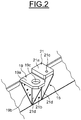
figure 2 représente une vue détaillée d'une patte de positionnement de lafigure 1 ; - la
figure 3 représente une vue en perspective d'un deuxième mode de réalisation d'un coffre à batterie selon un autre aspect de l'invention ; - la
figure 4 représente schématiquement le montage d'un coffre à batterie selon l'invention sur un véhicule ; - la
figure 5 représente une vue en perspective d'un sectionneur ; et - la
figure 6 représente un schéma électrique du coffre à batterie.
- the
figure 1 represents a perspective view of a first embodiment of a battery box according to the invention; - the
figure 2 represents a detailed view of a positioning tab of thefigure 1 ; - the
figure 3 is a perspective view of a second embodiment of a battery box according to another aspect of the invention; - the
figure 4 schematically shows the mounting of a battery box according to the invention on a vehicle; - the
figure 5 represents a perspective view of a disconnector; and - the
figure 6 represents a circuit diagram of the battery box.
Le coffre à batterie 1 représenté sur la
Le coffre à batterie 1 comprend une enveloppe externe 2, par exemple métallique, de forme générale parallélépipédique. L'enveloppe externe 2 délimite une chambre de réception 3 et comprend un support 4 et un couvercle amovible 5 reliés entre eux.The
Le support 4 se présente sous la forme d'une cuvette étanche obtenue par assemblage et/ou soudage de tôles d'épaisseur relativement mince. Le support 4 comprend un fond plat rectangulaire 6 et un cadre latéral 7.The
Ce cadre externe 7 présente un rebord périphérique 7a replié vers l'intérieur apte à coopérer avec une zone périphérique du couvercle 5.This
La chambre de réception 3 comprend un cloisonnement interne 3a délimitant des compartiments 8 dans lesquels sont disposés des blocs accumulateurs 9 renfermant chacun, dans des boîtiers, plusieurs éléments accumulateur d'énergie.The receiving chamber 3 comprises an
Tel qu'illustré sur la
Le coffre à batterie 1 peut comprendre un dispositif électrique ou électronique 11 de gestion des éléments accumulateurs d'énergie, disposé dans un compartiment spécifique 12. On notera que le compartiment spécifique 12 pourrait être intégré à l'enveloppe externe 2 du coffre à batterie 1.The
Comme illustré plus précisément sur les
Le coffre à batterie 1 tel que représenté sur la
A cet effet, deux pattes de positionnement 15 et 16 et deux pattes de fixation 17 et 18 sont situées sur l'enveloppe externe 2 du coffre à batterie 1 diagonalement opposées les unes aux autres. Chaque patte 15, 16, 17 et 18 est située à un coin du coffre à batterie 1 et peut être fixée sur le cadre latéral 7 de l'enveloppe externe 2 par le biais de visseries.For this purpose, two
Les pattes de positionnement 15, 16 et les pattes de fixation 17, 18 présentent des formes générales en « équerre ». On définit comme « équerre », toute pièce métallique à angle droit à section en forme de L destinée à fixer des assemblages entre eux.The
Comme on peut le voir le mieux sur la
L'équerre de fixation 21 comprend une embase 21a et une plaque de fixation 21b destinée à la fixation sur le cadre 7 de l'enveloppe 2. L'équerre de fixation 21 comprend des nervures 21d de part et d'autre de l'équerre de fixation 21. Ces nervures 21d permettent de rigidifier la patte de fixation 15. Les deux équerres 19, 21 sont reliées entre elles par une des nervures 21d.The
La patte de positionnement 16 présente une équerre de positionnement 20 (
Les embases 19a et 20a peuvent avoir une forme semi-circulaire ou une forme rectangulaire ou carrée. L'embase 21a de l'équerre de fixation 21 présente un taraudage 21c (
La plaque de fixation 19b est illustrée sur les
On notera que les embases 19a et 21a sont disposées sensiblement au même niveau, en étant légèrement décalées, l'embase 21a se situant au dessus du niveau de l'embase 19a. Les deux embases 19a et 21a sont situées légèrement au dessus du niveau du couvercle 5. Les embases 20a et 22a sont quant à elles situées légèrement au dessous du niveau du fond 6. L'embase 17b est située sensiblement au niveau du fond 6 tandis que l'embase correspondante de la patte de fixation 18 est sensiblement au niveau du couvercle 5. Cette disposition dans l'espace des différentes embases présente l'avantage d'équilibrer au mieux le coffre à batterie 1 lors des opérations de montage qui s'en trouvent facilitées.Note that the
La patte de fixation 17 comprend une équerre 17a, avec une embase 17b. Deux nervures 17d sont fixées de chaque coté de l'équerre 17a. L'embase 17b présente un taraudage apte à coopérer avec une tige filetée (non représentée). La patte de fixation 17 est fixée au cadre 7 à un de ses coins.The
La deuxième patte de fixation 18, fixée au coin diamétralement opposé du cadre 7 par rapport à la patte de fixation 17 se trouve en face de l'équerre de fixation 21 de la patte de positionnement 15.The
Ainsi le coffre à batterie 1 peut être fixé à un véhicule par quatre points de fixation définis respectivement par les équerres de fixation 21 et 22 et les pattes de fixation 17 et 18.Thus the
Les pattes de positionnement 15, 16 et les pattes de fixation 17, 18 sont de préférence réalisées en matériau métallique.The
On notera que les équerres de fixation 21 et 22 pourraient être indépendantes des équerres de positionnement 19 et 20. De manière générale, les pattes de positionnement 15, 16 et les pattes de fixation 17, 18 pourraient être situées à d'autres endroits sur l'enveloppe externe 3 du coffre à batterie 1.It will be noted that the
Le nombre de points de fixation du coffre à batterie 1 sur un véhicule pourrait également être supérieur à quatre.The number of attachment points of the
Tel qu'illustré sur la
Le coffre à batterie 1 tel qu'illustré à la
De la même manière que la chambre de réception 3 illustrée à la
Le coffre de batterie 1, tel que représenté sur la
A cet effet, en plus de la patte de positionnement 16 et de la patte de fixation 17, montées sur l'enveloppe externe 2, une patte de positionnement 26 est montée à la fois sur l'enveloppe externe 2 et sur l'enveloppe externe 2a. Les deux pattes de positionnement 16 et 26 sont sensiblement diagonalement opposées l'une à l'autre. Deux pattes de fixation supplémentaires 27 et 28 sont montées sur l'enveloppe externe 2 et une patte de fixation 29 est montée à la fois sur l'enveloppe externe 2 et sur l'enveloppe externe 2a. Les pattes de fixation 27 et 28 sont situées latéralement de part et d'autre du coffre à batterie 1, et les pattes de fixation 17 et 29 sont sensiblement diagonalement opposées l'une à l'autre.For this purpose, in addition to the
La patte de positionnement 26 comprend un ensemble de positionnement 30 et un ensemble de fixation 31. L'ensemble de positionnement 30 est composé de deux équerres 32, 33 reliées par une embase 30a commune. Les équerres 32 et 33 comprennent chacune une plaque de fixation fixées respectivement à chacune des enveloppes externes 2 et 2a du coffre à batterie 1. Dans l'exemple illustré, ces plaques de fixation ont une forme générale triangulaire ; on notera qu'elles pourraient être de forme rectangulaire. L'embase 30a commune aux deux équerres 32 et 33 comporte un passage 30b de forme générale cylindrique. On notera que la forme du passage 30b pourrait être différente, par exemple, conique.The
L'ensemble de fixation 31 est composé de deux équerres de fixation 34, 35 reliées par une embase commune. Les équerres 34 et 35 comprennent chacune une plaque de fixation fixées respectivement à chacune des enveloppes externes 2 et 2a du coffre à batterie 1. Dans l'exemple illustré, les plaques de fixation ont une forme générale rectangulaire ; on notera qu'elles pourraient être de forme triangulaire. L'embase 31a commune aux deux équerres 34 et 35 comporte un taraudage.The fixing
L'ensemble de fixation 31, tel qu'illustré à la
La deuxième patte de fixation 29 présente sensiblement la même structure que l'ensemble de fixation 31 de la patte de positionnement 26.The
Les troisième et quatrième pattes de fixation 27, 28 comprennent chacune deux plaques de fixation 27a, 28a de part et d'autre d'une embase 27c, 28c de manière à former deux équerres. Chaque patte de fixation 27, 28 est montée latéralement sur l'enveloppe externe 2 du coffre à batterie 1. Deux nervures 27d, 28d sont fixées de chaque coté des pattes de fixation 27, 28. Chaque embase 27c, 28c comporte un taraudage apte à coopérer avec une tige filetée (non représentée). On notera que les embases 30a et 31a sont situées sensiblement au niveau du couvercle 5 c'est-à-dire au niveau de la séparation entre l'enveloppe externe 2 et l'enveloppe externe 2a. Les embases 27c et 28c se situent sensiblement au milieu du cadre 7.The third and fourth fixing lugs 27, 28 each comprise two fixing
On notera que les quatre pattes de fixation 17, 27, 28 et 29 pourraient être identiques.It will be noted that the four fixing
Le montage d'un coffre à batterie 1 selon la
Le véhicule 36 est illustré à titre d'exemple non limitatif. Le procédé de montage pourrait être adapté à tout type de véhicule automobile. Le montage du coffre à batterie 1 sous le châssis du véhicule 36 comprend une étape de positionnement et une étape de fixation du coffre à batterie 1.The
Avant de manipuler le coffre à batterie 1, il est nécessaire de déconnecter le sectionneur 13 du dispositif électronique 11 situé dans le compartiment spécifique 12. Pour cela, il convient de séparer l'organe amovible 13b, par exemple une barrette de coupure, de l'embase 13a située sur l'enveloppe externe 3 du coffre à batterie 1.Before handling the
Afin de positionner le coffre à batterie 1, on utilise deux plots de positionnement 37. Chaque plot de positionnement 37 est de forme générale cylindrique et comprend une extrémité cylindrique filetée 37a et une extrémité opposée conique non filetée 37b.In order to position the
La première étape consiste à visser l'extrémité filetée 37a du plot de positionnement 37 dans un taraudage (non représenté) prévu sous le châssis du véhicule 36. A cet effet, on peut prévoir soit de surélever le véhicule 36 par un dispositif d'élévation standard, soit de positionner le véhicule 36 au dessus d'une fosse prévue sur le sol, de manière à accéder sous le châssis du véhicule 36.The first step consists of screwing the threaded
Une fois les plots de positionnement 37 vissés sur le véhicule 36, il convient de créer un mouvement relatif entre le coffre à batterie 1 et le véhicule 36. A cet effet, on peut soit abaisser le véhicule 36 lorsque celui-ci a été surélevé, soit surélever le coffre à batterie 1, soit abaisser le véhicule 36 et surélever le coffre à batterie 1, de manière à positionner les plots de positionnement 37 dans les passages 19c et 20c prévus respectivement sur les pattes de positionnement 15 et 16.Once the
Lorsque chaque extrémité conique 37b des deux plots de positionnement 37 est insérée dans les passages 19c et 20c, on continue le mouvement relatif entre le coffre à batterie 1 et le véhicule 36 de façon à positionner le coffre à batterie 1 dans un logement (non représenté) situé sous le châssis du véhicule 36.When each
Les passages 19c et 20c ont avantageusement un diamètre légèrement supérieur au diamètre des plots de positionnement 37.The
Lorsque le coffre à batterie 1 est correctement positionné sous le châssis du véhicule 36, il convient de fixer le coffre à batterie 1 au châssis du véhicule 36. A cet effet, on utilise les pattes de fixation 17, 18 ainsi que les équerres de fixation 21 et 22 des pattes de positionnement 15 et 16. La fixation se fait, par exemple, par vissage. On notera que tout autre moyen permettant la fixation du coffre 1 sur le véhicule 36 peut être envisagé, telle qu'une fixation au quart de tour, par verrous ou par crochets.When the
Une fois le coffre à batterie 1 positionné et fixé au véhicule 36, on accouple la barrette de coupure 13b avec l'embase 13a du sectionneur 13, de manière à reconnecter le dispositif électronique 11 aux blocs 9 d'éléments accumulateur d'énergie.Once the
Pour procéder au démontage du coffre à batterie 1 du véhicule 36, on agit de la manière inverse. Dans un premier temps, la barrette de coupure 13b est séparée de l'embase 13a du sectionneur 13. Ensuite on dévisse les vis de fixation des pattes de fixation 17, 18 et des pattes de positionnement 15 et 16.To disassemble the
Lors d'un changement de coffre à batterie 1, il n'est pas toujours nécessaire de dévisser les plots de positionnement 37. En effet, une fois les plots de positionnement 37 vissés au châssis du véhicule 36, ils peuvent n'être dévissés que pour les changer lorsqu'ils sont défectueux.During a change of
On notera que le procédé de montage et démontage d'un coffre à batterie n'est pas limité au coffre à batterie décrit ci-dessus et s'applique à tout type de coffre à batterie sur lequel on fixe des pattes de positionnement aptes à recevoir des plots de positionnement.Note that the method of assembly and disassembly of a battery box is not limited to the battery box described above and applies to any type of battery box on which is fixed positioning tabs adapted to receive positioning pads.
Grâce à l'invention qui vient d'être décrite, le coffre à batterie est aisément et rapidement positionné et fixé sur un véhicule automobile électrique ou hybride.Thanks to the invention that has just been described, the battery box is easily and quickly positioned and fixed on an electric or hybrid motor vehicle.
Claims (11)
- Vehicle battery box (1) comprising at least one outer casing (2) delimiting a chamber (3) receiving the battery (9) and comprising a support (4) and a removable cover (5) connected to each other, the box (1) comprising a first positioning lug (15), a second positioning lug (16) and lugs (17, 18) for fixing said battery box (1) to the vehicle, said positioning lugs (15, 16) and said fixing lugs (17, 18) being mounted on the outer casing (2), characterized in that each positioning lug (15, 16) comprises a positioning L-shaped bracket (19, 20) and a fixing L-shaped bracket (21,22) connected to the positioning bracket, said brackets (19, 20, 21, 22) being fixed to the outer casing (2) of the battery box (1), each positioning bracket (19, 20) comprises a base (19a, 20a) comprising a passage (19c, 20c) receiving a positioning stud (37) having a threaded end (37a) adapted to be screwed into a screwthread provided under the chassis of the vehicle and a conical end (37b) adapted to be inserted in the receiving passage (19c, 20c), and a fixing plate (19b) designed to be fixed on the casing (2) of the battery box, and each fixing bracket (21, 22) comprises a base (21a, 22a) and a fixing plate (21b, 22b) designed to be fixed on the casing (2) of the battery box (1), said bases (19a, 21a) of the fist positioning bracket (15) being disposed at substantially the same level, slightly above the level of the cover (5), and said bases (20a, 22a) of the second positioning bracket (16) being for their part are situated slightly below the level of the bottom 6.
- Battery box according to any one of Claims 1 to 4, comprising a second outer casing (2a) delimiting a second battery receiving chamber and comprising a cover (5a) placed over the first cover (5).
- Battery box according to Claim 2, wherein one positioning lugs (26) comprises two supplementary brackets (33, 35) connected to two first brackets (32, 34), said supplements brackets (33, 35) being mounted on the second outer casing (2a).
- Battery box according to any one of the preceding claims, comprising internal partitions (3a) delimiting compartments (8) in said receiving chamber (3), said compartments (8) being adapted to receive energy storage cell units (9).
- Battery box according to any one of the preceding claims, comprising at least one exterior recess (13c) for receiving a removable member (13b) of an isolator (13) connected to the battery.
- Method of mounting a battery box on a vehicle, said battery box (1) comprising at least one outer casing (2) delimiting a chamber (3) receiving the battery, characterized in that:- positioning studs (37) are screwed to the vehicle (36),- the battery box (1) is placed on the vehicle (36) so that the positioning studs (37) are inserted in positioning lugs (15, 16) provided on said battery box (1), each positioning lug (15, 16) comprises a positioning L-shaped bracket (19, 20) and a fixing L-shaped bracket (21,22) connected to the positioning bracket, said brackets (19, 20, 21, 22) being fixed to the outer casing (2) of the battery box (1), each positioning bracket (19, 20) comprises a base (19a, 20a) comprising a passage (19c, 20c) receiving a positioning stud (37) having a threaded end (37a) adapted to be screwed into a screwthread provided under the chassis of the vehicle and a conical end (37b) adapted to be inserted in the receiving passage (19c, 20c), and a fixing plate (19b) designed to be fixed on the casing (2) of the battery box, and each fixing bracket (21, 22) comprises a base (21a, 22a) and a fixing plate (21b, 22b) designed to be fixed on the casing (2) of the battery box (1), said bases (19a, 21a) of the fist positioning bracket (15) being disposed at substantially the same level, slightly above the level of the cover (5), and said bases (20a, 22a) of the second positioning bracket (16) being for their part are situated slightly below the level of the bottom 6, and- the battery box (1) is fixed to the vehicle (36) by means of fixing lugs (17, 18) provided on the battery box (1).
- Mounting method according Claim 6, wherein two positioning studs (37) are screwed to the vehicle (36).
- Mounting method according to either one of Claims 6 or 7, wherein the vehicle (36) is lowered and/or the battery box (1) is raised to carry out the positioning step.
- Mounting method according to any one of Claims 6 to 8, wherein, when positioning the battery box, the positioning lugs (15, 16) are guided by conical ends (37b) of the positioning studs (37).
- Mounting method according to any one of Claims 6 to 9, wherein the fixing lugs (17, 18) are fixed to the vehicle (36) by means of bolts.
- Mounting method according to any one of Claims 6 to 10, wherein, before manipulating the battery box (1), a removable member (13b) if separated from an isolator (13) connected to the battery to isolate the battery box (1) from an electronic device (11) for management of said battery box (1).
Applications Claiming Priority (2)
| Application Number | Priority Date | Filing Date | Title |
|---|---|---|---|
| FR1053290A FR2959604B1 (en) | 2010-04-28 | 2010-04-28 | BATTERY BOX FOR ELECTRIC OR HYBRID VEHICLE AND METHOD OF MOUNTING ON THE VEHICLE |
| PCT/EP2011/056141 WO2011134824A2 (en) | 2010-04-28 | 2011-04-18 | Battery box for electric or hybrid vehicle and method for mounting said box on the vehicle |
Publications (2)
| Publication Number | Publication Date |
|---|---|
| EP2564449A2 EP2564449A2 (en) | 2013-03-06 |
| EP2564449B1 true EP2564449B1 (en) | 2018-03-21 |
Family
ID=43102578
Family Applications (1)
| Application Number | Title | Priority Date | Filing Date |
|---|---|---|---|
| EP11714577.1A Not-in-force EP2564449B1 (en) | 2010-04-28 | 2011-04-18 | Battery box for electric or hybrid vehicle and method for mounting said box on the vehicle |
Country Status (5)
| Country | Link |
|---|---|
| US (1) | US9033084B2 (en) |
| EP (1) | EP2564449B1 (en) |
| CN (1) | CN102844906B (en) |
| FR (1) | FR2959604B1 (en) |
| WO (1) | WO2011134824A2 (en) |
Families Citing this family (45)
| Publication number | Priority date | Publication date | Assignee | Title |
|---|---|---|---|---|
| JP5656071B2 (en) * | 2010-12-28 | 2015-01-21 | スズキ株式会社 | Electric vehicle |
| DE102011112572A1 (en) | 2011-09-08 | 2013-03-14 | GM Global Technology Operations LLC (n. d. Gesetzen des Staates Delaware) | Replaceable battery module for an electric vehicle |
| FR2987000A1 (en) * | 2012-02-16 | 2013-08-23 | Peugeot Citroen Automobiles Sa | Support for battery tray of assembly module of electric car, has frame surrounding battery tray and comprising side section having segment relative to plate, where section forms acute angle with corresponding side of tray |
| CN103661305A (en) * | 2013-08-06 | 2014-03-26 | 湖北文理学院 | High-safety quick-changing battery box locking device |
| DE102014100334A1 (en) * | 2014-01-14 | 2015-07-16 | Dr. Ing. H.C. F. Porsche Aktiengesellschaft | Method and device for changing a battery of a hybrid or electric vehicle |
| CN104022242A (en) * | 2014-06-23 | 2014-09-03 | 南车戚墅堰机车有限公司 | Mounted storage battery tank for internal combustion locomotive |
| US10358169B2 (en) * | 2015-03-06 | 2019-07-23 | Ford Global Technologies, Llc | Coverless battery assembly for electrified vehicle |
| DE102015225188B4 (en) * | 2015-12-15 | 2020-10-08 | Bayerische Motoren Werke Aktiengesellschaft | Energy storage module |
| US10573863B2 (en) * | 2016-02-24 | 2020-02-25 | Phillips & Temro Industries Inc. | Battery and auxiliary power unit mounting system |
| CN105644338B (en) * | 2016-03-02 | 2018-03-20 | 合肥国轩高科动力能源有限公司 | A kind of dental inlay type lockable mechanism of electric automobile battery box |
| USD874394S1 (en) * | 2016-04-04 | 2020-02-04 | The Raymond Corporation | Battery enclosure |
| WO2018033880A2 (en) | 2016-08-17 | 2018-02-22 | Shape Corp. | Battery support and protection structure for a vehicle |
| GB2555826B (en) * | 2016-11-11 | 2019-11-20 | Jaguar Land Rover Ltd | Battery support arrangement |
| DE102016123553A1 (en) * | 2016-12-06 | 2018-06-07 | Dr. Ing. H.C. F. Porsche Aktiengesellschaft | Vehicle body for an electrically driven vehicle |
| WO2018127832A1 (en) | 2017-01-04 | 2018-07-12 | Shape Corp. | Vehicle battery tray structure with nodal modularity |
| JP6686948B2 (en) * | 2017-03-23 | 2020-04-22 | トヨタ自動車株式会社 | Vehicle substructure |
| DE102017206986A1 (en) * | 2017-04-26 | 2018-10-31 | Mahle International Gmbh | accumulator |
| WO2018213475A1 (en) | 2017-05-16 | 2018-11-22 | Shape Corp. | Polarized battery tray for a vehicle |
| WO2018213383A1 (en) | 2017-05-16 | 2018-11-22 | Shape Corp. | Vehicle battery tray with integrated battery retention and support features |
| WO2018213306A1 (en) | 2017-05-16 | 2018-11-22 | Shape Corp. | Vehicle battery tray having tub-based component |
| CN111108015A (en) | 2017-09-13 | 2020-05-05 | 形状集团 | Vehicle battery tray with tubular peripheral wall |
| CN111201155A (en) | 2017-10-04 | 2020-05-26 | 形状集团 | Battery tray bottom plate assembly for electric vehicle |
| EP3511184A1 (en) * | 2018-01-15 | 2019-07-17 | MAGNA STEYR Fahrzeugtechnik AG & Co KG | Motor vehicle with a support structure |
| WO2019169080A1 (en) | 2018-03-01 | 2019-09-06 | Shape Corp. | Cooling system integrated with vehicle battery tray |
| US10953926B2 (en) * | 2018-03-12 | 2021-03-23 | Ford Global Technologies, Llc | Protective cage assemblies for electrified vehicle battery packs |
| US11688910B2 (en) | 2018-03-15 | 2023-06-27 | Shape Corp. | Vehicle battery tray having tub-based component |
| CN110770060A (en) * | 2018-03-22 | 2020-02-07 | 深圳市大富科技股份有限公司 | Electric vehicle and chassis assembly, pressing block assembly and battery assembly thereof |
| CN108790760A (en) * | 2018-05-16 | 2018-11-13 | 浙江零跑科技有限公司 | A kind of Battery pack installation structure of electric vehicle |
| CN109094393A (en) * | 2018-07-24 | 2018-12-28 | 陈倩 | A kind of battery carrying device structure based on electric automobile chassis |
| JP2020035717A (en) * | 2018-08-31 | 2020-03-05 | 本田技研工業株式会社 | Battery pack and method for manufacturing battery pack |
| US11059361B2 (en) | 2018-09-04 | 2021-07-13 | Ford Global Technologies, Llc | High voltage battery pack support and isolation for electrified vehicles |
| US10618425B2 (en) * | 2018-09-10 | 2020-04-14 | Ford Global Technologies, Llc | High voltage battery pack mounting systems for electrified vehicles |
| CN109638192A (en) * | 2018-12-14 | 2019-04-16 | 蜂巢能源科技有限公司 | Mounting structure and lower case for battery pack |
| CN112086590A (en) * | 2019-05-27 | 2020-12-15 | 广州汽车集团股份有限公司 | Electric automobile battery, tightening mechanism and battery installation method |
| US11772504B2 (en) * | 2019-08-22 | 2023-10-03 | Ioan Sasu | Fast rechargeable battery assembly and recharging equipment |
| CN111640900A (en) * | 2020-07-24 | 2020-09-08 | 厦门海辰新能源科技有限公司 | Fixed knot constructs and battery box |
| DE102020209366A1 (en) | 2020-07-24 | 2022-01-27 | Mahle International Gmbh | Electrical battery module and motor vehicle |
| CN112864517B (en) * | 2020-12-31 | 2023-01-24 | 江苏安全技术职业学院 | New energy automobile battery box |
| CN113036304A (en) * | 2021-03-08 | 2021-06-25 | 顺加能科技有限公司 | Battery integration device for new energy vehicle and new energy vehicle |
| FR3120579A1 (en) * | 2021-03-12 | 2022-09-16 | Psa Automobiles Sa | MOTOR VEHICLE ELECTRIC BATTERY CHARGER SUPPORT |
| FR3120578A1 (en) * | 2021-03-12 | 2022-09-16 | Psa Automobiles Sa | MOTOR VEHICLE ELECTRIC BATTERY CHARGER SUPPORT |
| FR3120580B1 (en) * | 2021-03-12 | 2023-02-10 | Psa Automobiles Sa | MOTOR VEHICLE BATTERY CHARGER SUPPORT DEVICE |
| JPWO2022249409A1 (en) * | 2021-05-27 | 2022-12-01 | ||
| CN216529124U (en) * | 2021-11-18 | 2022-05-13 | 湖北亿纬动力有限公司 | Battery system |
| FR3140310A1 (en) * | 2022-10-04 | 2024-04-05 | Psa Automobiles Sa | ELECTRIC OR HYBRID VEHICLE BATTERY BOX COVER DEVICE WITH INTERMEDIATE SHIMS |
Citations (1)
| Publication number | Priority date | Publication date | Assignee | Title |
|---|---|---|---|---|
| US4365681A (en) * | 1980-12-22 | 1982-12-28 | General Motors Corporation | Battery support structure |
Family Cites Families (10)
| Publication number | Priority date | Publication date | Assignee | Title |
|---|---|---|---|---|
| US5392873A (en) * | 1992-01-22 | 1995-02-28 | Honda Giken Kogyo Kabushiki Kaisha | Structure for securing batteries used in an electric vehicle |
| JP3350189B2 (en) * | 1993-04-30 | 2002-11-25 | 本田技研工業株式会社 | Battery box device for electric vehicles |
| US5612606A (en) * | 1994-09-15 | 1997-03-18 | David C. Guimarin | Battery exchange system for electric vehicles |
| SE507909C2 (en) * | 1996-02-02 | 1998-07-27 | Reservatet I Hovaas Hb | Device for mounting and connecting battery packs in electric vehicles |
| US5639571A (en) * | 1996-06-24 | 1997-06-17 | General Motors Corporation | Battery pack |
| US6197444B1 (en) * | 1998-08-26 | 2001-03-06 | Toshiba International Corporation | Battery case |
| JP4507903B2 (en) * | 2004-05-28 | 2010-07-21 | トヨタ自動車株式会社 | Interlock device |
| JP4363350B2 (en) * | 2005-03-30 | 2009-11-11 | トヨタ自動車株式会社 | Secondary battery cooling structure |
| JP2007134138A (en) * | 2005-11-09 | 2007-05-31 | Nissan Motor Co Ltd | Battery pack |
| JP5151363B2 (en) * | 2007-09-28 | 2013-02-27 | 三菱自動車工業株式会社 | Battery case for electric vehicles |
-
2010
- 2010-04-28 FR FR1053290A patent/FR2959604B1/en not_active Expired - Fee Related
-
2011
- 2011-04-18 CN CN201180019803.6A patent/CN102844906B/en not_active Expired - Fee Related
- 2011-04-18 US US13/695,604 patent/US9033084B2/en not_active Expired - Fee Related
- 2011-04-18 WO PCT/EP2011/056141 patent/WO2011134824A2/en active Application Filing
- 2011-04-18 EP EP11714577.1A patent/EP2564449B1/en not_active Not-in-force
Patent Citations (1)
| Publication number | Priority date | Publication date | Assignee | Title |
|---|---|---|---|---|
| US4365681A (en) * | 1980-12-22 | 1982-12-28 | General Motors Corporation | Battery support structure |
Also Published As
| Publication number | Publication date |
|---|---|
| WO2011134824A3 (en) | 2011-12-29 |
| FR2959604A1 (en) | 2011-11-04 |
| US9033084B2 (en) | 2015-05-19 |
| EP2564449A2 (en) | 2013-03-06 |
| CN102844906B (en) | 2016-02-24 |
| US20130192913A1 (en) | 2013-08-01 |
| WO2011134824A2 (en) | 2011-11-03 |
| FR2959604B1 (en) | 2012-12-07 |
| CN102844906A (en) | 2012-12-26 |
Similar Documents
| Publication | Publication Date | Title |
|---|---|---|
| EP2564449B1 (en) | Battery box for electric or hybrid vehicle and method for mounting said box on the vehicle | |
| EP2145360B1 (en) | Module for an electric energy storage assembly | |
| FR2883665A1 (en) | POWER SUPPLY DEVICE FOR MOTOR VEHICLE | |
| FR2959603A1 (en) | RIGIDIFIED BATTERY BOX FOR AN ELECTRIC OR HYBRID VEHICLE | |
| FR2924857A1 (en) | ELECTRICAL SUPPLY DEVICE COMPRISING A RECEPTION UNIT FOR ULTRA CAPACITY STORAGE UNITS | |
| WO2011134828A1 (en) | Compartmented battery box for an electric or hybrid vehicle | |
| EP2299552B1 (en) | Box intended to receive a low-voltage electrical device associated with a medium-voltage switchgear cell | |
| EP3377351A1 (en) | Public transport electric land vehicle with optimised architecture | |
| EP2810286B1 (en) | Strut positioning, electric energy storage module using it, and module assembly process | |
| CA2871272A1 (en) | Energy storage module containing a plurality of energy storage elements and improved means of thermal dissipation and method of assembly | |
| EP2721911A1 (en) | Printed circuit for interconnecting and measuring battery cells in a battery | |
| FR2988915A3 (en) | Module structure for housing lithium-ion battery cells in battery module in e.g. electric vehicle, has case arranged to form spacing between adjacent walls perpendicular to basic wall, where thickness of basic wall is equal to that of cells | |
| FR2968460A1 (en) | ENERGY STORER FLASK | |
| EP3314682B1 (en) | Electric energy storage module | |
| EP4028273B1 (en) | Power supply assembly for a motor vehicle | |
| FR3127637A1 (en) | Protection device for prismatic electrochemical accumulator | |
| EP1166376B1 (en) | Box for set of electric storage batteries | |
| FR3081085A1 (en) | ELECTRICAL SAFETY AND CABLE CONNECTION BOX (S) COMPRISING A PYROTECHNIC DEVICE AND FUSES | |
| WO2020201536A1 (en) | Capacitive block comprising a spacer | |
| EP3667688B1 (en) | Electrical assembly comprising a capacitive element | |
| WO2023099566A1 (en) | Electric battery with a vertical configuration | |
| WO2024088936A1 (en) | Power supply assembly of an electric motor vehicle | |
| FR2832856A1 (en) | Container for batteries, comprises base and lid dimensioned to suit number of batteries preferably without liquid electrolyte, interconnections and electronic means to balance currents and voltages | |
| EP0020277A1 (en) | Accumulator battery and electric household apparatus that may be equipped with at least one such battery | |
| FR3051605A1 (en) | ELECTRICAL BATTERY HIGH VOLTAGE SECURED |
Legal Events
| Date | Code | Title | Description |
|---|---|---|---|
| PUAI | Public reference made under article 153(3) epc to a published international application that has entered the european phase |
Free format text: ORIGINAL CODE: 0009012 |
|
| 17P | Request for examination filed |
Effective date: 20121011 |
|
| AK | Designated contracting states |
Kind code of ref document: A2 Designated state(s): AL AT BE BG CH CY CZ DE DK EE ES FI FR GB GR HR HU IE IS IT LI LT LU LV MC MK MT NL NO PL PT RO RS SE SI SK SM TR |
|
| DAX | Request for extension of the european patent (deleted) | ||
| 17Q | First examination report despatched |
Effective date: 20170131 |
|
| RAP1 | Party data changed (applicant data changed or rights of an application transferred) |
Owner name: COMPAGNIE GENERALE DES ETABLISSEMENTS MICHELIN |
|
| RAP1 | Party data changed (applicant data changed or rights of an application transferred) |
Owner name: COMPAGNIE GENERALE DES ETABLISSEMENTS MICHELIN |
|
| GRAP | Despatch of communication of intention to grant a patent |
Free format text: ORIGINAL CODE: EPIDOSNIGR1 |
|
| RIC1 | Information provided on ipc code assigned before grant |
Ipc: B60L 11/18 20060101ALI20171030BHEP Ipc: B60K 1/04 20060101ALI20171030BHEP Ipc: H01M 2/10 20060101AFI20171030BHEP |
|
| INTG | Intention to grant announced |
Effective date: 20171122 |
|
| GRAS | Grant fee paid |
Free format text: ORIGINAL CODE: EPIDOSNIGR3 |
|
| GRAA | (expected) grant |
Free format text: ORIGINAL CODE: 0009210 |
|
| AK | Designated contracting states |
Kind code of ref document: B1 Designated state(s): AL AT BE BG CH CY CZ DE DK EE ES FI FR GB GR HR HU IE IS IT LI LT LU LV MC MK MT NL NO PL PT RO RS SE SI SK SM TR |
|
| REG | Reference to a national code |
Ref country code: GB Ref legal event code: FG4D Free format text: NOT ENGLISH |
|
| REG | Reference to a national code |
Ref country code: CH Ref legal event code: EP |
|
| REG | Reference to a national code |
Ref country code: AT Ref legal event code: REF Ref document number: 981982 Country of ref document: AT Kind code of ref document: T Effective date: 20180415 |
|
| REG | Reference to a national code |
Ref country code: IE Ref legal event code: FG4D Free format text: LANGUAGE OF EP DOCUMENT: FRENCH |
|
| REG | Reference to a national code |
Ref country code: DE Ref legal event code: R096 Ref document number: 602011046662 Country of ref document: DE |
|
| REG | Reference to a national code |
Ref country code: FR Ref legal event code: PLFP Year of fee payment: 8 |
|
| REG | Reference to a national code |
Ref country code: NL Ref legal event code: MP Effective date: 20180321 |
|
| PG25 | Lapsed in a contracting state [announced via postgrant information from national office to epo] |
Ref country code: FI Free format text: LAPSE BECAUSE OF FAILURE TO SUBMIT A TRANSLATION OF THE DESCRIPTION OR TO PAY THE FEE WITHIN THE PRESCRIBED TIME-LIMIT Effective date: 20180321 Ref country code: HR Free format text: LAPSE BECAUSE OF FAILURE TO SUBMIT A TRANSLATION OF THE DESCRIPTION OR TO PAY THE FEE WITHIN THE PRESCRIBED TIME-LIMIT Effective date: 20180321 Ref country code: NO Free format text: LAPSE BECAUSE OF FAILURE TO SUBMIT A TRANSLATION OF THE DESCRIPTION OR TO PAY THE FEE WITHIN THE PRESCRIBED TIME-LIMIT Effective date: 20180621 Ref country code: CY Free format text: LAPSE BECAUSE OF FAILURE TO SUBMIT A TRANSLATION OF THE DESCRIPTION OR TO PAY THE FEE WITHIN THE PRESCRIBED TIME-LIMIT Effective date: 20180321 Ref country code: LT Free format text: LAPSE BECAUSE OF FAILURE TO SUBMIT A TRANSLATION OF THE DESCRIPTION OR TO PAY THE FEE WITHIN THE PRESCRIBED TIME-LIMIT Effective date: 20180321 |
|
| PGFP | Annual fee paid to national office [announced via postgrant information from national office to epo] |
Ref country code: DE Payment date: 20180420 Year of fee payment: 8 |
|
| REG | Reference to a national code |
Ref country code: LT Ref legal event code: MG4D |
|
| REG | Reference to a national code |
Ref country code: AT Ref legal event code: MK05 Ref document number: 981982 Country of ref document: AT Kind code of ref document: T Effective date: 20180321 |
|
| PG25 | Lapsed in a contracting state [announced via postgrant information from national office to epo] |
Ref country code: BG Free format text: LAPSE BECAUSE OF FAILURE TO SUBMIT A TRANSLATION OF THE DESCRIPTION OR TO PAY THE FEE WITHIN THE PRESCRIBED TIME-LIMIT Effective date: 20180621 Ref country code: RS Free format text: LAPSE BECAUSE OF FAILURE TO SUBMIT A TRANSLATION OF THE DESCRIPTION OR TO PAY THE FEE WITHIN THE PRESCRIBED TIME-LIMIT Effective date: 20180321 Ref country code: SE Free format text: LAPSE BECAUSE OF FAILURE TO SUBMIT A TRANSLATION OF THE DESCRIPTION OR TO PAY THE FEE WITHIN THE PRESCRIBED TIME-LIMIT Effective date: 20180321 Ref country code: LV Free format text: LAPSE BECAUSE OF FAILURE TO SUBMIT A TRANSLATION OF THE DESCRIPTION OR TO PAY THE FEE WITHIN THE PRESCRIBED TIME-LIMIT Effective date: 20180321 Ref country code: GR Free format text: LAPSE BECAUSE OF FAILURE TO SUBMIT A TRANSLATION OF THE DESCRIPTION OR TO PAY THE FEE WITHIN THE PRESCRIBED TIME-LIMIT Effective date: 20180622 |
|
| PGFP | Annual fee paid to national office [announced via postgrant information from national office to epo] |
Ref country code: FR Payment date: 20180420 Year of fee payment: 8 |
|
| PG25 | Lapsed in a contracting state [announced via postgrant information from national office to epo] |
Ref country code: MT Free format text: LAPSE BECAUSE OF FAILURE TO SUBMIT A TRANSLATION OF THE DESCRIPTION OR TO PAY THE FEE WITHIN THE PRESCRIBED TIME-LIMIT Effective date: 20180321 |
|
| PG25 | Lapsed in a contracting state [announced via postgrant information from national office to epo] |
Ref country code: IT Free format text: LAPSE BECAUSE OF FAILURE TO SUBMIT A TRANSLATION OF THE DESCRIPTION OR TO PAY THE FEE WITHIN THE PRESCRIBED TIME-LIMIT Effective date: 20180321 Ref country code: EE Free format text: LAPSE BECAUSE OF FAILURE TO SUBMIT A TRANSLATION OF THE DESCRIPTION OR TO PAY THE FEE WITHIN THE PRESCRIBED TIME-LIMIT Effective date: 20180321 Ref country code: NL Free format text: LAPSE BECAUSE OF FAILURE TO SUBMIT A TRANSLATION OF THE DESCRIPTION OR TO PAY THE FEE WITHIN THE PRESCRIBED TIME-LIMIT Effective date: 20180321 Ref country code: RO Free format text: LAPSE BECAUSE OF FAILURE TO SUBMIT A TRANSLATION OF THE DESCRIPTION OR TO PAY THE FEE WITHIN THE PRESCRIBED TIME-LIMIT Effective date: 20180321 Ref country code: ES Free format text: LAPSE BECAUSE OF FAILURE TO SUBMIT A TRANSLATION OF THE DESCRIPTION OR TO PAY THE FEE WITHIN THE PRESCRIBED TIME-LIMIT Effective date: 20180321 Ref country code: PL Free format text: LAPSE BECAUSE OF FAILURE TO SUBMIT A TRANSLATION OF THE DESCRIPTION OR TO PAY THE FEE WITHIN THE PRESCRIBED TIME-LIMIT Effective date: 20180321 Ref country code: AL Free format text: LAPSE BECAUSE OF FAILURE TO SUBMIT A TRANSLATION OF THE DESCRIPTION OR TO PAY THE FEE WITHIN THE PRESCRIBED TIME-LIMIT Effective date: 20180321 |
|
| RAP2 | Party data changed (patent owner data changed or rights of a patent transferred) |
Owner name: COMPAGNIE GENERALE DES ETABLISSEMENTS MICHELIN |
|
| PG25 | Lapsed in a contracting state [announced via postgrant information from national office to epo] |
Ref country code: AT Free format text: LAPSE BECAUSE OF FAILURE TO SUBMIT A TRANSLATION OF THE DESCRIPTION OR TO PAY THE FEE WITHIN THE PRESCRIBED TIME-LIMIT Effective date: 20180321 Ref country code: SK Free format text: LAPSE BECAUSE OF FAILURE TO SUBMIT A TRANSLATION OF THE DESCRIPTION OR TO PAY THE FEE WITHIN THE PRESCRIBED TIME-LIMIT Effective date: 20180321 Ref country code: SM Free format text: LAPSE BECAUSE OF FAILURE TO SUBMIT A TRANSLATION OF THE DESCRIPTION OR TO PAY THE FEE WITHIN THE PRESCRIBED TIME-LIMIT Effective date: 20180321 Ref country code: CZ Free format text: LAPSE BECAUSE OF FAILURE TO SUBMIT A TRANSLATION OF THE DESCRIPTION OR TO PAY THE FEE WITHIN THE PRESCRIBED TIME-LIMIT Effective date: 20180321 |
|
| REG | Reference to a national code |
Ref country code: CH Ref legal event code: PL |
|
| REG | Reference to a national code |
Ref country code: BE Ref legal event code: MM Effective date: 20180430 |
|
| PG25 | Lapsed in a contracting state [announced via postgrant information from national office to epo] |
Ref country code: PT Free format text: LAPSE BECAUSE OF FAILURE TO SUBMIT A TRANSLATION OF THE DESCRIPTION OR TO PAY THE FEE WITHIN THE PRESCRIBED TIME-LIMIT Effective date: 20180723 |
|
| REG | Reference to a national code |
Ref country code: DE Ref legal event code: R097 Ref document number: 602011046662 Country of ref document: DE |
|
| REG | Reference to a national code |
Ref country code: IE Ref legal event code: MM4A |
|
| PLBE | No opposition filed within time limit |
Free format text: ORIGINAL CODE: 0009261 |
|
| STAA | Information on the status of an ep patent application or granted ep patent |
Free format text: STATUS: NO OPPOSITION FILED WITHIN TIME LIMIT |
|
| PG25 | Lapsed in a contracting state [announced via postgrant information from national office to epo] |
Ref country code: MC Free format text: LAPSE BECAUSE OF FAILURE TO SUBMIT A TRANSLATION OF THE DESCRIPTION OR TO PAY THE FEE WITHIN THE PRESCRIBED TIME-LIMIT Effective date: 20180321 Ref country code: LU Free format text: LAPSE BECAUSE OF NON-PAYMENT OF DUE FEES Effective date: 20180418 Ref country code: DK Free format text: LAPSE BECAUSE OF FAILURE TO SUBMIT A TRANSLATION OF THE DESCRIPTION OR TO PAY THE FEE WITHIN THE PRESCRIBED TIME-LIMIT Effective date: 20180321 |
|
| 26N | No opposition filed |
Effective date: 20190102 |
|
| GBPC | Gb: european patent ceased through non-payment of renewal fee |
Effective date: 20180621 |
|
| PG25 | Lapsed in a contracting state [announced via postgrant information from national office to epo] |
Ref country code: LI Free format text: LAPSE BECAUSE OF NON-PAYMENT OF DUE FEES Effective date: 20180430 Ref country code: CH Free format text: LAPSE BECAUSE OF NON-PAYMENT OF DUE FEES Effective date: 20180430 Ref country code: BE Free format text: LAPSE BECAUSE OF NON-PAYMENT OF DUE FEES Effective date: 20180430 |
|
| PG25 | Lapsed in a contracting state [announced via postgrant information from national office to epo] |
Ref country code: GB Free format text: LAPSE BECAUSE OF NON-PAYMENT OF DUE FEES Effective date: 20180621 Ref country code: IE Free format text: LAPSE BECAUSE OF NON-PAYMENT OF DUE FEES Effective date: 20180418 |
|
| PG25 | Lapsed in a contracting state [announced via postgrant information from national office to epo] |
Ref country code: SI Free format text: LAPSE BECAUSE OF FAILURE TO SUBMIT A TRANSLATION OF THE DESCRIPTION OR TO PAY THE FEE WITHIN THE PRESCRIBED TIME-LIMIT Effective date: 20180321 |
|
| REG | Reference to a national code |
Ref country code: DE Ref legal event code: R119 Ref document number: 602011046662 Country of ref document: DE |
|
| PG25 | Lapsed in a contracting state [announced via postgrant information from national office to epo] |
Ref country code: DE Free format text: LAPSE BECAUSE OF NON-PAYMENT OF DUE FEES Effective date: 20191101 |
|
| PG25 | Lapsed in a contracting state [announced via postgrant information from national office to epo] |
Ref country code: FR Free format text: LAPSE BECAUSE OF NON-PAYMENT OF DUE FEES Effective date: 20190430 |
|
| PG25 | Lapsed in a contracting state [announced via postgrant information from national office to epo] |
Ref country code: TR Free format text: LAPSE BECAUSE OF FAILURE TO SUBMIT A TRANSLATION OF THE DESCRIPTION OR TO PAY THE FEE WITHIN THE PRESCRIBED TIME-LIMIT Effective date: 20180321 |
|
| PG25 | Lapsed in a contracting state [announced via postgrant information from national office to epo] |
Ref country code: HU Free format text: LAPSE BECAUSE OF FAILURE TO SUBMIT A TRANSLATION OF THE DESCRIPTION OR TO PAY THE FEE WITHIN THE PRESCRIBED TIME-LIMIT; INVALID AB INITIO Effective date: 20110418 |
|
| PG25 | Lapsed in a contracting state [announced via postgrant information from national office to epo] |
Ref country code: MK Free format text: LAPSE BECAUSE OF NON-PAYMENT OF DUE FEES Effective date: 20180321 |
|
| PG25 | Lapsed in a contracting state [announced via postgrant information from national office to epo] |
Ref country code: IS Free format text: LAPSE BECAUSE OF FAILURE TO SUBMIT A TRANSLATION OF THE DESCRIPTION OR TO PAY THE FEE WITHIN THE PRESCRIBED TIME-LIMIT Effective date: 20180721 |