EP2564094B1 - Vacuumregelventil für vakuumdrainagesystem - Google Patents
Vacuumregelventil für vakuumdrainagesystem Download PDFInfo
- Publication number
- EP2564094B1 EP2564094B1 EP11718866.4A EP11718866A EP2564094B1 EP 2564094 B1 EP2564094 B1 EP 2564094B1 EP 11718866 A EP11718866 A EP 11718866A EP 2564094 B1 EP2564094 B1 EP 2564094B1
- Authority
- EP
- European Patent Office
- Prior art keywords
- valve
- aperture
- movable member
- vacuum
- open area
- Prior art date
- Legal status (The legal status is an assumption and is not a legal conclusion. Google has not performed a legal analysis and makes no representation as to the accuracy of the status listed.)
- Active
Links
Images







Classifications
-
- F—MECHANICAL ENGINEERING; LIGHTING; HEATING; WEAPONS; BLASTING
- F16—ENGINEERING ELEMENTS AND UNITS; GENERAL MEASURES FOR PRODUCING AND MAINTAINING EFFECTIVE FUNCTIONING OF MACHINES OR INSTALLATIONS; THERMAL INSULATION IN GENERAL
- F16K—VALVES; TAPS; COCKS; ACTUATING-FLOATS; DEVICES FOR VENTING OR AERATING
- F16K3/00—Gate valves or sliding valves, i.e. cut-off apparatus with closing members having a sliding movement along the seat for opening and closing
- F16K3/02—Gate valves or sliding valves, i.e. cut-off apparatus with closing members having a sliding movement along the seat for opening and closing with flat sealing faces; Packings therefor
- F16K3/16—Gate valves or sliding valves, i.e. cut-off apparatus with closing members having a sliding movement along the seat for opening and closing with flat sealing faces; Packings therefor with special arrangements for separating the sealing faces or for pressing them together
-
- F—MECHANICAL ENGINEERING; LIGHTING; HEATING; WEAPONS; BLASTING
- F16—ENGINEERING ELEMENTS AND UNITS; GENERAL MEASURES FOR PRODUCING AND MAINTAINING EFFECTIVE FUNCTIONING OF MACHINES OR INSTALLATIONS; THERMAL INSULATION IN GENERAL
- F16K—VALVES; TAPS; COCKS; ACTUATING-FLOATS; DEVICES FOR VENTING OR AERATING
- F16K3/00—Gate valves or sliding valves, i.e. cut-off apparatus with closing members having a sliding movement along the seat for opening and closing
- F16K3/30—Details
- F16K3/34—Arrangements for modifying the way in which the rate of flow varies during the actuation of the valve
-
- F—MECHANICAL ENGINEERING; LIGHTING; HEATING; WEAPONS; BLASTING
- F16—ENGINEERING ELEMENTS AND UNITS; GENERAL MEASURES FOR PRODUCING AND MAINTAINING EFFECTIVE FUNCTIONING OF MACHINES OR INSTALLATIONS; THERMAL INSULATION IN GENERAL
- F16K—VALVES; TAPS; COCKS; ACTUATING-FLOATS; DEVICES FOR VENTING OR AERATING
- F16K5/00—Plug valves; Taps or cocks comprising only cut-off apparatus having at least one of the sealing faces shaped as a more or less complete surface of a solid of revolution, the opening and closing movement being predominantly rotary
- F16K5/08—Details
- F16K5/12—Arrangements for modifying the way in which the rate of flow varies during the actuation of the valve
-
- F—MECHANICAL ENGINEERING; LIGHTING; HEATING; WEAPONS; BLASTING
- F16—ENGINEERING ELEMENTS AND UNITS; GENERAL MEASURES FOR PRODUCING AND MAINTAINING EFFECTIVE FUNCTIONING OF MACHINES OR INSTALLATIONS; THERMAL INSULATION IN GENERAL
- F16K—VALVES; TAPS; COCKS; ACTUATING-FLOATS; DEVICES FOR VENTING OR AERATING
- F16K51/00—Other details not peculiar to particular types of valves or cut-off apparatus
- F16K51/02—Other details not peculiar to particular types of valves or cut-off apparatus specially adapted for high-vacuum installations
Definitions
- the invention relates to vacuum valves used to control the amount of negative pressure applied to a suction device in filtration operations, and particularly in papermaking machines.
- the invention particularly concerns a vacuum control valve that includes an adjustable aperture, such that the rate of change of its open area increases non-linearly in relation to the adjustment, while providing substantially linearly variable vacuum pressure.
- vacuum As used herein, the terms “vacuum”, “suction” and “negative pressure” have equivalent meanings and refer to an amount of air pressure developed in a confined space (e.g. piping, suction chamber, etc.) that is lower than ambient atmospheric air pressure.
- a confined space e.g. piping, suction chamber, etc.
- the invention is applicable to various types of filtration operation, but is particularly suitable for filtration in papermaking processes.
- the invention is described below primarily in relation to papermaking processes, it should be understood that the principles of the invention are not limited thereto, and can be applied to other filtration processes having similar requirements to papermaking processes.
- a very dilute slurry comprising about 1% papermaking solids in about 99% water (referred to as the "stock") is jetted at high speed and precision from a headbox onto an endless rotating belt called a forming fabric.
- the stock jet is aimed so that it lands on the forming fabric as the fabric passes in sliding contact over a forming element.
- Water from the stock drains through the forming fabric, leaving behind an embryonic mat of papermaking fibers and solids.
- the forming fabric and mat thereon pass over one or more drainage, agitation and suction devices which serve to both drain water and randomize the fiber distribution so as to provide a fibrous web.
- This web is transferred at the end of the forming section to a downstream press section where a further portion of the water is removed by mechanical means; the wet sheet is subsequently transferred to a dryer section of the papermaking machine where the remainder of the water in the web is removed by evaporative means.
- Controlled sources of vacuum are used in the forming and press sections of the papermaking machine to assist in removal of water from the web and to help control agitation of the stock. Due to the highly fluid nature of the stock in the forming section, precise control of the vacuum pressure applied to the forming fabric and embryonic web through the drainage and agitation devices is very important to the properties of the finished sheet. Other factors which raise the requirement for precise control in the press section of the papermaking machine are noted below.
- suction assisted drainage devices There are two general categories of suction assisted drainage devices presently used in papermaking processes: a) so-called low vacuum units, which supply from 0 to 60" (0 to 1500mm) of water vacuum to the forming fabric and web, and b) high vacuum units, which supply a higher vacuum level to the fabrics and web than low vacuum units. It has been found that valves presently in use in both of these types of suction assisted drainage devices do not provide acceptably consistent vacuum control outside the middle portion of their operating ranges.
- the problem of reliably controlling the vacuum pressure applied to the forming fabric in particular is further complicated as a mat of papermaking fibers is built up during the sheet formation process.
- the amount of fiber and fillers present on a forming fabric during the papermaking process will be dependent on the paper grade being manufactured.
- Relatively "heavier” grades i.e., products having relatively higher basis weights
- linerboard or cardboard will comprise greater amounts of fiber than comparatively "lighter” paper grades (i.e., those having comparatively lower basis weights), such as newsprint or towel, or fine papers.
- the heavier paper grades will form a thicker mat, which will provide greater resistance to air flow in comparison to a mat formed for a lighter grade application.
- the present invention therefore addresses the problem of valve size and design selection for use in connection with a suction assisted drainage device, and is particularly directed at the unique operating conditions and environments in which these vacuum devices are located in papermaking processes.
- the present invention is particularly concerned with a valve apparatus which is used to control the amount of vacuum applied to the suction assisted drainage elements so that the applied vacuum varies linearly as the valve is opened or closed in response to adjustment from a very low to a very high level of vacuum pressure.
- the valve is designed to provide a nonlinear continuously increasing rate of change in open area which provides a linear vacuum response that is directly proportional to the valve aperture position over up to at least about 90% of its operating range.
- valve aperture, or open area, of the valves of the invention allows for a linear change in the fluid flow rate (vacuum) in response to gradual linear adjustments of the valve from fully closed to fully open.
- This allows a single valve to be used for both high and low flow environments with more effective control of vacuum under both conditions. With a single valve for all positions in a papermaking vacuum system, changes in operating conditions do not require a change in valve size, thus significantly reducing the cost of spares.
- the valves of the invention provide a relatively linear change in the amount of vacuum pressure applied to the papermaking process in response to their adjustment; depending on the vacuum range being controlled, this change is directly proportional to the amount of open area provided to the vacuum source as the valve is opened or closed.
- the single valves of the invention can be provided as rotary sleeve type valves, in which the flow rate is regulated by adjusting the operational area of an aperture in the rotary sleeve presented to a valve body outlet, or can be provided as other types of movable valve, for example by providing the aperture in a movable member such that the operational area presented to the valve body outlet is adjusted by moving the member in a selected direction in relation to that outlet.
- EP 1744 086 A1 and WO 01/03162 disclose prior art valves according to the preamble of claim 1.
- valve aperture is configured such that in response to linear adjustment in the movable member of the valve to increase the open area, the rate of change of open area increases in a nonlinear manner, but provides a linear change in the flow rate through the aperture.
- the vacuum control aperture is shaped so as to provide a smooth, linear vacuum response to the amount of open area presented to the vacuum source and the amount of vacuum applied to the suction box through the valve. It has further been found to be particularly advantageous if the vacuum control aperture is shaped such that the rate of change in the amount of open area of the vacuum control opening presented to the vacuum drainage system to which it is connected at any point of the movement of the movable member, for example by rotation of a valve sleeve from fully closed to fully open, is determinable by a polynomial equation of at least the second degree. This configuration provides for a relatively slow increase in open area in the initial adjustment from a fully closed position to a partly open position, and at the same time a rapid increase in the open area as the adjustment brings the valve near to the fully open position.
- the invention therefore seeks to provide a valve for use in a vacuum drainage system, comprising the features of claim 1.
- the at least one aperture has a configuration such that during movement of the movable member in operation, a linear increase in the distance of travel provides a substantially linear increase in fluid flow through the effective operational area of the at least one aperture.
- the interior chamber comprises a substantially cylindrical interior
- the movable member is a rotatable sleeve secured within the substantially cylindrical interior and having a substantially cylindrical outer wall
- the outlet aperture is provided to the substantially cylindrical outer wall
- the movement of the sleeve through the distance of travel comprises rotation about an axis.
- the movable member is a slidable plate member.
- the valve comprises a single aperture.
- such single aperture has a configuration which is substantially trilateral, and more preferably includes at least one curved side.
- the aperture configuration is defined by substantially linear first and second edges and a third edge connected to and having a curvature towards each of the first and second edges, and in this aspect preferably the first edge is substantially parallel to the axis and the second edge is substantially perpendicular to the first edge; more preferably the first edge and the second edge are of substantially equal length.
- the curvature is selected from partial parabolic, arcuate, and a curve defined by a plurality of mutually connected linear segments.
- the curvature is defined according to an equation including at least one exponential factor, preferably according to a polynomial equation of at least a third degree, more preferably of a fourth degree.
- the aperture configuration comprises a plurality of wall connection members defining a plurality of sub-apertures, preferably having a configuration selected from at least one of slots and perforations.
- the exterior wall of the valve body further comprises a vent operatively connectable to a source of ambient atmospheric air; and the movable member further comprises a movable member inlet operably alignable with the vent.
- a movable member inlet has a quadrilateral configuration, and where the movable member is a rotatable sleeve, preferably the movable member inlet has a trapezoidal configuration, wherein two parallel sides are oriented substantially parallel to the direction of rotation of the movable member.
- valve 100 comprises a valve body 112, with an outlet flange 110 for connection to a vacuum source (not shown) and an inlet flange 113 for connection to the appropriate location in the equipment (not shown) in a papermaking process.
- Optional vent 111 provides access for ambient atmospheric air.
- the valves of the invention can be provided without such vents, depending on the intended end use, or if provided, the vent may be selectively blocked or otherwise stopped to prevent or restrict access of ambient air.
- Valve sleeve 105 is operationally secured to actuator 200 (see Figure 2 ), protectively located beneath valve cover 102, by drive flange 106, so that when valve cover 102 is secured over valve body 112, valve sleeve 105 is selectively rotatable within valve body 112, the rotation being controlled by actuator 200.
- the wall of sleeve 105 is provided with an outlet aperture 107, which is configured according to the invention, and located so as to be operationally brought into and out of alignment with the outlet at flange 110 and thereby connection with the vacuum source, allowing for a flow path in the direction of arrow 250 ( Figure 2 ).
- valve sleeve 105 can correspondingly be provided with an inlet aperture 108, configured and located so as to be operationally brought into and out of alignment with vent 111, on rotation of valve sleeve 105, to selectively allow or restrict the passage of ambient air through vent 111 into valve sleeve 105, through a flow path in the direction of arrow 350 ( Figure 3 ).
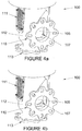
- valve sleeve outlet aperture 107 within valve body 112, as valve sleeve 105 is rotated to cause outlet aperture 107 to move from a closed position in Fig. 4a to a fully open position in Fig. 4d .
- vent 111 the locations of inlet aperture 108 and outlet aperture 107 in the wall of valve sleeve 105 are spaced apart such that on rotation of valve sleeve 105 to close inlet aperture 108 and close the ambient air intake, and open outlet aperture 107 to connect to the vacuum source, inlet aperture 108 is preferably completely closed before the opening of outlet aperture 107 commences.
- the outlet aperture 107 and the inlet aperture 108 can be located on valve sleeve 105 such that both can be simultaneously, to a minor degree, open to flow.
- Figure 5 shows valve 100 with flange 110 removed so that outlet aperture 107 is visible in the fully open position, similar to the position in Figure 4d .
- FIG 6 shows valve sleeve 105 including outlet aperture 107 and inlet aperture 108.
- valve bottom 115 When fully assembled, valve bottom 115 would be located above and proximate to flange 113. Opening 114 provides for operational connection of actuator 200 ( Figure 2 ) to sleeve 105 via drive flange 106 ( Figure 1 ) to allow transmission of rotational force.
- Figure 7 is a graph showing the amount of open area of the valve outlet aperture 107 in an embodiment of the invention, as a function of its rotation from fully closed to fully open.
- the curve shows the amount of open area of the valve sleeve outlet aperture 107 that must be exposed to vacuum pressure in order to provide a substantially linear response in applied vacuum as a function of valve sleeve rotation and the increasing rate of change in open area.
- Inspection of the graph of Figure 7 shows that, as the valve sleeve 105 is rotated so that its position changes from fully closed at position (0) to fully open at position (1), the open area of the valve outlet aperture, expressed as a percentage of the total available aperture area, changes from 0 to 100% along the curve.
- 0% rotation (Valve Rotation Position 0.0) provides zero open area of the valve outlet aperture 107.
- the open area of the valve outlet aperture is 0.7%
- the valve aperture presents 3% open area to the vacuum drainage system
- the valve aperture presents 6% open area, thus conforming to the desirability of a relatively slow increase in open area in the first stages of movement from the closed position.
- the valve aperture presents respectively 34%, 48%, 69% open area to the vacuum drainage system, providing the desirable sharp increase in open area in the positions approaching the fully open (100%) position.
- this increasing rate of change is preferably determinable by a polynomial equation of at least the second degree. More particularly preferred features, including suitable polynomial equations and numeric values, are discussed above.
- valves comprising rotatable sleeves and having apertures with open areas which vary in the general manner indicated in Table 1 can provide a generally linearly varying vacuum pressure to the vacuum drainage system to which they are connected, as a function of the rotation of valve sleeve 105.
- a mat of fibers is formed on the forming fabric, and this mat is dewatered in part by the suction force applied to the underside of the fabric by the vacuum dewatering units.
- the paper product formed on the mat provides a high filtration resistance (i.e., the resistance to the passage of air through the mat due to applied suction is relatively high, e.g.
- the ratio of the open area of the valve A valve to the open area of the vacuum drainage system piping A pipe is preferably low when the valve is first opened, so as to provide the desired linear vacuum response as the valve is opened.
- the ratio A valve /A pipe increase more rapidly than for the higher resistant mat when the valve is first opened.
- the outlet aperture 107 shown in Figure 6 has been found to be an effective shape for use in embodiments of the present invention having rotary sleeve valves.
- a valve according to the invention was made, the sleeve 105 being formed from a continuous PTFE (polytrifluoroethylene, or Teflon®) tube with an outside diameter of 7.0 inches (17.78cm), an inside diameter of 5.5 inches (13.97cm), and a height of 9.875 inches (25.083cm).
- PTFE polytrifluoroethylene, or Teflon®
- the trilateral outlet aperture provided in the tube had two substantially equal straight sides, one parallel and the other perpendicular to the axis of rotation of the sleeve; each straight side was 6.6 inches (16.764cm) in length and these two sides were connected to each other by a curve to form a trilateral opening having an open area which increased according to the invention, i.e. with an increasing rate of change as the aperture moved from the closed position towards the open position.
- the sleeve 105 was provided with an inlet aperture 108; this aperture is trapezoidal in shape having an overall length of 5.75 inches (14.61cm), one end being 1.938 inches (4.92cm) wide, the other being 2.50 inches (6.35cm) wide.
- valve sleeve 105 was installed in a valve body 112 as part of valve 100 substantially as shown in Figures 1 to 3 and vacuum applied through piping attached to flange 110 which passed through valve 100 to a papermaking process via further piping attached to flange connection 113. Rotation of valve sleeve 105 via drive assembly 200 produced a variance in vacuum pressure applied to the papermaking process that was substantially linear in accordance with the objectives of the invention.
- Figure 8 is a graph showing the relative change in the open area of the valve body outlet as a function of valve sleeve position according to a second embodiment of the invention.
- two sides of the trilateral aperture are curved and the apex of the trilateral aperture is oriented towards the direction of rotation of the valve sleeve.
- the open area will in this case be twice that of the portion shown above the x axis.
- the apertures of the invention can be of numerous shapes, not necessarily symmetrical, provided that they result in the appropriate increased rate of change of open area in relation to the distance of movement of the movable member.
- Table 2 Valve Open Area Changing Symmetrically in Two Directions Valve Position Open Area (Side A) Open Area (Side B) Total Open Area (Side A + Side B) 0.0 0.0 0.0 0.0 0.0 0.1 0.35 0.35 0.7 0.2 1.5 1.5 3 0.3 3 3 6 0.4 5 5 10 0.5 8 8 16 0.6 12 12 24 0.7 17 17 34 0.8 24 24 48 0.9 34 34 69 1.0 50 50 100
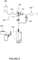
- FIG 9 shows valve 100 of the present invention as located in a typical papermaking vacuum system.
- the valve 100 is operably connected by outlet flange 110 to vacuum source 400, and by inlet flange 113 to an air/water separator device 402 and thus to the papermaking drainage unit 403.
- Vacuum pressure information is transmitted via line 404 to a vacuum sensor in valve 100 and vacuum control information is transmitted via shielded cordset line 405 to and from controller 406, which regulates actuator 200 ( Figure 2 ) in the valve 100, so as to rotate sleeve 105 ( Figure 2 ) and adjust vacuum pressure in the system according to need.
- Line 401 provides a by-pass in the event that vacuum control via valve 100 is not required, or when the valve must be removed for service.
- FIGs 10 to 12 show respectively a valve 360 according to a second embodiment of the invention provided with a movable valve member such as slide member 305 ( Figure 11 ), and three schematic illustrations of the valve in operation.
- a planar valve slide member 305 replaces the rotary sleeve member used in the embodiment of Figures 1 to 6 .
- valve 360 comprises a valve body 312 provided with valve outlet 317 for connection to a vacuum source and valve inlet 318 for connection to the appropriate location in the equipment (not shown) in a papermaking process.
- Slide member 305 is operationally secured to actuator 300 so that slide member 305 can be selectively positioned within valve body 312.
- Slide member 305 is provided with inlet apertures 308a and 308b configured and located so as to be operationally brought into and out of alignment with a vent 311in valve body 312 on movement of the slide member 305 to selectively allow or restrict the passage of ambient air through the vent and into valve body 312.
- the slide member 305 is further provided with an outlet aperture 307 which is configured according to the invention so as to provide the required rate of change in open area and located so as to be operationally brought into and out of alignment with the valve outlet 317 and thereby connection with the vacuum source, allowing for a flow of negative pressure from the vacuum source.
- FIGS 12a to 12c these cross-sectional figures show the progressive opening of outlet aperture 307 and corresponding closing of inlet apertures 308a and 308b as the slide member 305 is moved from a fully closed position in Figure 12a to a fully open position in Figure 12c .
- the locations of inlet apertures 308a and 308b, and outlet aperture 307, are spaced apart such that, upon sliding movement of slide member 305 to close inlet apertures 308a and 308b, and to open outlet aperture 307 to connect to the vacuum source (as shown in Figures 12a and 12b ) the inlet apertures 308a and 308b are preferably completely closed before the opening of outlet aperture 307 commences.
- Figure 12a shows the valve body 312 of the vacuum valve 360 (see Figure 10 ) with the inlet apertures 308a, 308b in the fully open, or bleed, position, and the outlet aperture 307 in the fully closed position;
- Figure 12b shows the vacuum valve 360 with the outlet aperture 307 in a partially open position and the inlet apertures 308a, 308b in the fully closed position;
- Figure 12c shows the vacuum valve 360 with the outlet aperture 307 in the fully open position and the inlet apertures 308a, 308b in the fully closed position.
- outlet aperture 307 is presented as a trilateral aperture having two opposed curved sides.
- the shape of outlet aperture 307 is designed such that the open area presented to the valve outlet 317 at each position provides the desired rate of change in open area, as discussed further above, and as exemplified in Table 2.
- the shape of outlet aperture 307 may be generally triangular, such as is shown in Figures 5 and 6 , or it may comprise a plurality of slots, drilled holes or other suitable perforations, in each case located in relation to each other in a manner such that they present the appropriate rate of change in open area, and thus provide the advantageous linear change in vacuum pressure as a function of opening or closing the valve.
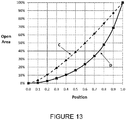
- Figure 13 is a graph depicting the percentage open area of a valve according to the present invention, in comparison to a ball type prior art valve such as commonly used in a papermaking process.
- the percentage open area of the prior art valve is shown on the Y-axis as a function of valve position for various values along the X-axis, and identified by line C.
- the line identified as D provides corresponding information for a valve in an embodiment of the present invention.
- the open area C of the prior art valve changes substantially linearly with respect to changes in position between fully closed and fully open, going from approximately 5% open at position 0.1, to about 10% open at position 0.2, to about 20% fully open at position 0.3, up to 90% open at position 0.9.
- this generally linear change in open area in response to position change in the prior art valve C does not provide a directly proportional change in vacuum pressure, and results in significantly reduced efficiency when the valve is in a position approaching fully open.
- FIG 14 this is a graph providing a comparison between the rate of change in open area as a function of valve position for a prior art valve, and a valve in accordance with the present invention.
- the prior art valve of Figure 14 is of the same general type as the prior art valve identified by line C in Figure 13 .
- the rate of change in open area for the prior art valve, between the fully closed and fully open positions, is identified by line E in Figure 14 , and it can be seen that the rate of change increases significantly in the early stages starting from the fully closed position, slows significantly in the intermediate stages, and approaches a constant level in the later stages approaching the fully open position, i.e. as line E approaches the horizontal.
Landscapes
- Engineering & Computer Science (AREA)
- General Engineering & Computer Science (AREA)
- Mechanical Engineering (AREA)
- Sliding Valves (AREA)
- Details Of Valves (AREA)
Claims (11)
- Ventil (100) zur Verwendung in einem Vakuumdrainagesystem, wobei das Ventil Folgendes umfasst:(i) ein Ventilgehäuse (102), das Folgendes aufweist:(a) eine Außenwand, die einen Einlass (113), der wirksam mit einem Ausgang aus einer Saugeinrichtung verbunden werden kann, und einen Auslass (110), der wirksam mit einer Vakuumquelle (400) verbunden werden kann, umfasst, und(b) eine innere Kammer,(ii) ein bewegliches Element (105), das beweglich innerhalb der inneren Kammer befestigt ist und wenigstens eine Auslassöffnung (107) des beweglichen Elements umfasst, um selektiv eine offene Betriebsfläche bereitzustellen, die dafür aufgebaut und angeordnet ist, einen Fluidstrom durch dieselbe zu ermöglichen, unddadurch gekennzeichnet, dass die Änderungsgeschwindigkeit der wirksamen Betriebsfläche gemäß einer Polynomgleichung y = ax4 + bx3 + cx2 + dx + e zunimmt, wobei(a) das dafür angeordnet ist, derart mit dem Ventilgehäuseauslass (110) zusammenzuwirken, dass eine Bewegung des beweglichen Elements (105) durch eine Bewegungsstrecke durch ausgewählte einer Vielzahl von Positionen zwischen einer Position mit vollständig geschlossener Öffnung und einer Position mit vollständig offener Öffnung wenigstens einen Abschnitt der wenigstens einen Öffnung dem Ventilgehäuseauslass (110) bietet, um die wirksame offene Betriebsfläche der Öffnung, die dem Ventilgehäuseauslass (110) geboten wird, einzustellen und um im Betrieb eine entsprechende Durchflussmenge durch die wenigstens eine Öffnung und den Ventilgehäuseauslass (110) zu regulieren, und(b) das eine derartige Konfiguration aufweist, dass während einer Bewegung des beweglichen Elements (105), um die wirksame Betriebsfläche der wenigstens einen Öffnung zu steigern, eine Änderungsgeschwindigkeit der wirksamen Betriebsfläche nichtlinear im Verhältnis zu einer linearen Zunahme bei der Bewegungsstrecke zunimmt,
y die Änderungsgeschwindigkeit der wirksamen Betriebsfläche ist,
x die Bewegungsstrecke des beweglichen Elements ist, ausgedrückt als eine Dezimalzahl, die von einer vollständig geschlossenen Öffnungsposition bei 0,0 bis zu einer vollständig offenen Öffnungsposition bei 1,0 reicht,


- Ventil nach Anspruch 1, wobei die wenigstens eine Öffnung eine derartige Konfiguration aufweist, dass während einer Bewegung des beweglichen Elements im Betrieb eine lineare Zunahme bei der Bewegungsstrecke eine im Wesentlichen lineare Zunahme beim Fluidstrom durch die wirksame Betriebsfläche der wenigstens einen Öffnung gewährleistet.
- Ventil nach Anspruch 1 oder 2, wobei die innere Kammer ein im Wesentlichen zylindrisches Inneres umfasst, das bewegliche Element eine drehbare Hülse ist, die innerhalb des im Wesentlichen zylindrischen Inneren befestigt ist und eine im Wesentlichen zylindrische Außenwand aufweist, die Auslassöffnung an der im Wesentlichen zylindrischen Außenwand bereitgestellt wird und die Bewegung der Hülse durch die Bewegungsstrecke eine Drehung um eine Achse umfasst.
- Ventil nach Anspruch 1 oder 2, wobei das bewegliche Element ein verschiebbares Plattenelement ist.
- Ventil nach einem der Ansprüche 1 bis 4, das eine einzige Öffnung umfasst.
- Ventil nach Anspruch 5, wobei die Öffnung eine Konfiguration aufweist, die im Wesentlichen dreiseitig ist und definiert wird durch im Wesentlichen lineare erste und zweite Kanten und eine dritte Kante, die mit sowohl der ersten als auch der zweiten Kante verbunden ist und eine Krümmung zu denselben hin aufweist, wobei die erste Kante im Wesentlichen parallel zu der Achse ist und die zweite Kante im Wesentlichen senkrecht zu der ersten Kante ist, wobei die erste Kante und die zweite Kante im Wesentlichen von gleicher Länge sind und die Krümmung ausgewählt ist von teilweise parabolisch, bogenförmig und einer Krümmung, die durch eine Vielzahl von wechselseitig verbundenen linearen Segmenten definiert wird.
- Ventil nach Anspruch 6, wobei die Krümmung definiert wird durch eine Polynomgleichung, die ausgewählt ist von einer Polynomgleichung dritten Grades und einer Polynomgleichung vierten Grades, wobei y = fx4 + gx3 + hx2 + jx + k, wobei
y die Krümmung ist und
x die Bewegungsstrecke des beweglichen Elements ist, ausgedrückt als eine Dezimalzahl, die von einer vollständig geschlossenen Öffnungsposition bei 0,0 bis zu einer vollständig offenen Öffnungsposition bei 1,0 reicht. - Ventil nach Anspruch 7, wobei die Polynomgleichung eine vierten Grades ist, wobei y = fx4 + gx3 + hx2 + jx + k und f = 1,18, g = - 0,39, h = - 0,16, j = 0,37 und k=0.
- Ventil nach Anspruch 1, wobei die Außenwand des Ventilgehäuses ferner eine Lüftungsöffnung (111) umfasst, die mit einer Quelle umgebender Atmosphärenluft wirksam verbunden werden kann, und das bewegliche Element ferner einen Einlass (108) des beweglichen Elements umfasst, der wirksam mit der Lüftungsöffnung (111) ausgerichtet werden kann.
- Ventil nach Anspruch 9, wobei der Einlass des beweglichen Elements eine vierseitige Konfiguration aufweist.
- Ventil nach Anspruch 10, wobei das bewegliche Element eine drehbare Hülse ist und das bewegliche Element eine trapezförmige Konfiguration aufweist, wobei zwei parallele Seiten im Wesentlichen parallel zu der Drehrichtung des beweglichen Elements ausgerichtet sind.
Priority Applications (1)
| Application Number | Priority Date | Filing Date | Title |
|---|---|---|---|
| PL11718866T PL2564094T3 (pl) | 2010-04-30 | 2011-04-29 | Próżniowy zawór regulacyjny do próżniowego układu odwadniającego |
Applications Claiming Priority (2)
| Application Number | Priority Date | Filing Date | Title |
|---|---|---|---|
| US32978310P | 2010-04-30 | 2010-04-30 | |
| PCT/US2011/034448 WO2011137287A1 (en) | 2010-04-30 | 2011-04-29 | Vacuum control valve for vacuum drainage system |
Publications (2)
| Publication Number | Publication Date |
|---|---|
| EP2564094A1 EP2564094A1 (de) | 2013-03-06 |
| EP2564094B1 true EP2564094B1 (de) | 2018-08-08 |
Family
ID=44262474
Family Applications (1)
| Application Number | Title | Priority Date | Filing Date |
|---|---|---|---|
| EP11718866.4A Active EP2564094B1 (de) | 2010-04-30 | 2011-04-29 | Vacuumregelventil für vakuumdrainagesystem |
Country Status (5)
| Country | Link |
|---|---|
| US (1) | US9404588B2 (de) |
| EP (1) | EP2564094B1 (de) |
| CN (1) | CN102947630B (de) |
| PL (1) | PL2564094T3 (de) |
| WO (1) | WO2011137287A1 (de) |
Families Citing this family (3)
| Publication number | Priority date | Publication date | Assignee | Title |
|---|---|---|---|---|
| US10316982B2 (en) * | 2014-07-10 | 2019-06-11 | Borgwarner Inc. | Curved shunt for solenoid curve shaping |
| US10166036B2 (en) * | 2014-10-16 | 2019-01-01 | Gyrus Acmi, Inc. | Variable suction control |
| US10559451B2 (en) * | 2017-02-15 | 2020-02-11 | Applied Materials, Inc. | Apparatus with concentric pumping for multiple pressure regimes |
Family Cites Families (25)
| Publication number | Priority date | Publication date | Assignee | Title |
|---|---|---|---|---|
| US2995359A (en) * | 1958-08-18 | 1961-08-08 | Harris Intertype Corp | Sheet feeder |
| US3409270A (en) * | 1965-10-04 | 1968-11-05 | Eldon E. Hulsey | Variable orifice plug-type valve |
| US3355220A (en) * | 1966-03-17 | 1967-11-28 | Brown Warren Durand | Concrete valve structure |
| US3557821A (en) * | 1969-08-01 | 1971-01-26 | Pace Inc | By-pass valve |
| US3896194A (en) * | 1974-06-06 | 1975-07-22 | Frank T Martin | Carburetor idle control means |
| US3998227A (en) * | 1974-09-13 | 1976-12-21 | Medical Development Corporation | Regulator structure and system |
| US4918768A (en) * | 1987-11-18 | 1990-04-24 | Jacuzzi Whirlpool Bath | Air valve for spas and baths |
| FI81895C (fi) * | 1988-12-30 | 1990-12-10 | Neles Oy | Reglerventil. |
| DE4137811C2 (de) * | 1991-11-16 | 1994-01-20 | Westfalia Separator Ag | Meßgerät zur Messung des Luftdurchflusses in Melkanlagen |
| US5174320A (en) * | 1992-01-03 | 1992-12-29 | Halliburton Company | Bulk cement metering device |
| US5242150A (en) * | 1992-09-30 | 1993-09-07 | The United States Of America As Represented By The Secretary Of The Navy | Rotary hydraulic servo or throttle valve |
| WO1994009207A2 (en) * | 1992-10-14 | 1994-04-28 | Valmet Paper Machinery Inc. | Twin-wire former with simultaneous drainage suction boxes |
| US5338166A (en) * | 1993-02-16 | 1994-08-16 | Pioneering Concepts Incorporated | Evacuation pump system for both rigid and flexible containers |
| US6109591A (en) * | 1996-10-25 | 2000-08-29 | Tuttle; James D. | Wide range proportional flow control valve |
| US5895028A (en) * | 1997-09-23 | 1999-04-20 | Uop Llc | Single disc slide valve with center biased flow |
| DE19744190C2 (de) * | 1997-09-30 | 2000-08-03 | Schmalz J Gmbh | Unterdruckhandhabungsgerät |
| CN1223350A (zh) * | 1998-01-09 | 1999-07-21 | 格瑞斯伍德控制公司 | 用于节流球阀的插头 |
| JP2000346217A (ja) * | 1999-06-07 | 2000-12-15 | Toyota Autom Loom Works Ltd | 逆止弁 |
| TW418296B (en) * | 1999-06-30 | 2001-01-11 | Koninkl Philips Electronics Nv | A low-pressure apparatus for carrying out steps in the manufacture of a device, a method of manufacturing a device making use of such an apparatus, and a pressure control valve |
| ATE354695T1 (de) * | 2001-05-15 | 2007-03-15 | Voith Patent Gmbh | Maschine zur herstellung einer faserstoffbahn aus einer faserstoffsuspension, verfahren zur überwachung eines entwässerungselements einer papiermaschine und papiermaschine mit einem system zur überwachung eines entwässerungselements |
| US6843264B2 (en) * | 2002-12-18 | 2005-01-18 | Taiwan Semiconductor Manufacturing Co., Ltd. | Multi-phase pressure control valve for process chamber |
| KR100577561B1 (ko) * | 2004-01-12 | 2006-05-08 | 삼성전자주식회사 | 반도체 제조 설비의 배기압력 제어장치 |
| ITPR20050036A1 (it) * | 2005-07-15 | 2007-01-16 | Immergas Spa | Dispositivo regolatore della portata di un liquido circolante in una caldaia. |
| WO2007136517A2 (en) * | 2006-05-15 | 2007-11-29 | Hollis Thomas J | Digital rotary control valve |
| US8734736B2 (en) * | 2009-10-06 | 2014-05-27 | Lester F. Ludwig | Valve-manifold laboratory glassware for chemical laboratory automation and other application |
-
2011
- 2011-04-29 US US13/643,400 patent/US9404588B2/en active Active
- 2011-04-29 EP EP11718866.4A patent/EP2564094B1/de active Active
- 2011-04-29 CN CN201180026661.6A patent/CN102947630B/zh active Active
- 2011-04-29 WO PCT/US2011/034448 patent/WO2011137287A1/en not_active Ceased
- 2011-04-29 PL PL11718866T patent/PL2564094T3/pl unknown
Non-Patent Citations (1)
| Title |
|---|
| None * |
Also Published As
| Publication number | Publication date |
|---|---|
| CN102947630A (zh) | 2013-02-27 |
| US20140183390A1 (en) | 2014-07-03 |
| US9404588B2 (en) | 2016-08-02 |
| WO2011137287A1 (en) | 2011-11-03 |
| CN102947630B (zh) | 2015-01-21 |
| EP2564094A1 (de) | 2013-03-06 |
| PL2564094T3 (pl) | 2019-02-28 |
Similar Documents
| Publication | Publication Date | Title |
|---|---|---|
| CA1335088C (en) | Method and apparatus for treating fiber suspension | |
| GB2064613A (en) | Felt dewatering system | |
| US9404588B2 (en) | Vacuum control valve for vacuum drainage system | |
| CN108286492A (zh) | 斜轴结构的流体静力的轴向柱塞马达 | |
| GB2197935A (en) | Vacuum controller | |
| US4151859A (en) | Throttle shaft for the controlled discharge of dammed-up water | |
| US5082530A (en) | Method and device in headbox of paper, board or pulp drying machine | |
| DE10257447B4 (de) | Verdrängungssteuerungsvorrichtung zum Steuern einer Ausstoßmenge eines Kühlmittels | |
| CA2116268A1 (en) | Device and method for changing the flow resistance of a fluid flow control device | |
| DE3508736C2 (de) | ||
| US20110197976A1 (en) | Standpipe direct float valve | |
| JPH09508679A (ja) | セルフローディング式ロールの位置制御装置 | |
| CA2185747C (en) | Apparatus for a paper-making machine for delivering liquid from a first level to a second, higher level | |
| US4877059A (en) | Valve | |
| FI97306B (fi) | Paperi- tai kartonkikoneen kaksoisviiraformeri | |
| US4980027A (en) | Vari-flow headbox with large and small flow inlet systems | |
| EP3339648B1 (de) | Flüssigkeitspumpe mit einer luftansaugpumpe und, zwischen den zwei pumpen, einem durch schwimmer betätigten ventil | |
| KR101124475B1 (ko) | 유량조절밸브 | |
| EP3423627B1 (de) | Rundsiebpapiermaschine | |
| EP4625090A1 (de) | Turbinenfunktion in einem steuerventil | |
| WO1991001408A1 (en) | Improved system and method for forming and dewatering a web on a fourdrinier fabric | |
| EP1843234B2 (de) | Druckbegrenzungsventil, vozugsweise zur Regelung des Druckes im Kurbelgehäuse eines Verbrennungsmotors | |
| US6736937B2 (en) | Method and apparatus for controlling the operation of the short circulation of a paper, paperboard or the like production machine | |
| JP2001003339A (ja) | 定流量越流堰 | |
| EP0646743B1 (de) | Druckmittelbetätigtes Membranventil |
Legal Events
| Date | Code | Title | Description |
|---|---|---|---|
| PUAI | Public reference made under article 153(3) epc to a published international application that has entered the european phase |
Free format text: ORIGINAL CODE: 0009012 |
|
| 17P | Request for examination filed |
Effective date: 20121122 |
|
| AK | Designated contracting states |
Kind code of ref document: A1 Designated state(s): AL AT BE BG CH CY CZ DE DK EE ES FI FR GB GR HR HU IE IS IT LI LT LU LV MC MK MT NL NO PL PT RO RS SE SI SK SM TR |
|
| RIN1 | Information on inventor provided before grant (corrected) |
Inventor name: RONNING, JAMES Inventor name: MENDRALA, GEORGE C. Inventor name: SHANDS, JAY A. Inventor name: MCPHERSON, DOUGLAS R. |
|
| DAX | Request for extension of the european patent (deleted) | ||
| RAP1 | Party data changed (applicant data changed or rights of an application transferred) |
Owner name: PAPERCHINE INC. |
|
| STAA | Information on the status of an ep patent application or granted ep patent |
Free format text: STATUS: EXAMINATION IS IN PROGRESS |
|
| 17Q | First examination report despatched |
Effective date: 20161124 |
|
| RAP1 | Party data changed (applicant data changed or rights of an application transferred) |
Owner name: PAPERCHINE INC. |
|
| GRAP | Despatch of communication of intention to grant a patent |
Free format text: ORIGINAL CODE: EPIDOSNIGR1 |
|
| STAA | Information on the status of an ep patent application or granted ep patent |
Free format text: STATUS: GRANT OF PATENT IS INTENDED |
|
| INTG | Intention to grant announced |
Effective date: 20180220 |
|
| GRAS | Grant fee paid |
Free format text: ORIGINAL CODE: EPIDOSNIGR3 |
|
| GRAA | (expected) grant |
Free format text: ORIGINAL CODE: 0009210 |
|
| STAA | Information on the status of an ep patent application or granted ep patent |
Free format text: STATUS: THE PATENT HAS BEEN GRANTED |
|
| AK | Designated contracting states |
Kind code of ref document: B1 Designated state(s): AL AT BE BG CH CY CZ DE DK EE ES FI FR GB GR HR HU IE IS IT LI LT LU LV MC MK MT NL NO PL PT RO RS SE SI SK SM TR |
|
| RAP1 | Party data changed (applicant data changed or rights of an application transferred) |
Owner name: ANDRITZ INC. |
|
| REG | Reference to a national code |
Ref country code: GB Ref legal event code: FG4D |
|
| REG | Reference to a national code |
Ref country code: CH Ref legal event code: EP Ref country code: AT Ref legal event code: REF Ref document number: 1027395 Country of ref document: AT Kind code of ref document: T Effective date: 20180815 |
|
| REG | Reference to a national code |
Ref country code: IE Ref legal event code: FG4D |
|
| REG | Reference to a national code |
Ref country code: DE Ref legal event code: R096 Ref document number: 602011050792 Country of ref document: DE |
|
| REG | Reference to a national code |
Ref country code: SE Ref legal event code: TRGR |
|
| REG | Reference to a national code |
Ref country code: NL Ref legal event code: MP Effective date: 20180808 |
|
| REG | Reference to a national code |
Ref country code: LT Ref legal event code: MG4D |
|
| PG25 | Lapsed in a contracting state [announced via postgrant information from national office to epo] |
Ref country code: LT Free format text: LAPSE BECAUSE OF FAILURE TO SUBMIT A TRANSLATION OF THE DESCRIPTION OR TO PAY THE FEE WITHIN THE PRESCRIBED TIME-LIMIT Effective date: 20180808 Ref country code: IS Free format text: LAPSE BECAUSE OF FAILURE TO SUBMIT A TRANSLATION OF THE DESCRIPTION OR TO PAY THE FEE WITHIN THE PRESCRIBED TIME-LIMIT Effective date: 20181208 Ref country code: NO Free format text: LAPSE BECAUSE OF FAILURE TO SUBMIT A TRANSLATION OF THE DESCRIPTION OR TO PAY THE FEE WITHIN THE PRESCRIBED TIME-LIMIT Effective date: 20181108 Ref country code: GR Free format text: LAPSE BECAUSE OF FAILURE TO SUBMIT A TRANSLATION OF THE DESCRIPTION OR TO PAY THE FEE WITHIN THE PRESCRIBED TIME-LIMIT Effective date: 20181109 Ref country code: RS Free format text: LAPSE BECAUSE OF FAILURE TO SUBMIT A TRANSLATION OF THE DESCRIPTION OR TO PAY THE FEE WITHIN THE PRESCRIBED TIME-LIMIT Effective date: 20180808 Ref country code: BG Free format text: LAPSE BECAUSE OF FAILURE TO SUBMIT A TRANSLATION OF THE DESCRIPTION OR TO PAY THE FEE WITHIN THE PRESCRIBED TIME-LIMIT Effective date: 20181108 Ref country code: NL Free format text: LAPSE BECAUSE OF FAILURE TO SUBMIT A TRANSLATION OF THE DESCRIPTION OR TO PAY THE FEE WITHIN THE PRESCRIBED TIME-LIMIT Effective date: 20180808 |
|
| PG25 | Lapsed in a contracting state [announced via postgrant information from national office to epo] |
Ref country code: HR Free format text: LAPSE BECAUSE OF FAILURE TO SUBMIT A TRANSLATION OF THE DESCRIPTION OR TO PAY THE FEE WITHIN THE PRESCRIBED TIME-LIMIT Effective date: 20180808 Ref country code: AL Free format text: LAPSE BECAUSE OF FAILURE TO SUBMIT A TRANSLATION OF THE DESCRIPTION OR TO PAY THE FEE WITHIN THE PRESCRIBED TIME-LIMIT Effective date: 20180808 Ref country code: LV Free format text: LAPSE BECAUSE OF FAILURE TO SUBMIT A TRANSLATION OF THE DESCRIPTION OR TO PAY THE FEE WITHIN THE PRESCRIBED TIME-LIMIT Effective date: 20180808 |
|
| PG25 | Lapsed in a contracting state [announced via postgrant information from national office to epo] |
Ref country code: CZ Free format text: LAPSE BECAUSE OF FAILURE TO SUBMIT A TRANSLATION OF THE DESCRIPTION OR TO PAY THE FEE WITHIN THE PRESCRIBED TIME-LIMIT Effective date: 20180808 Ref country code: RO Free format text: LAPSE BECAUSE OF FAILURE TO SUBMIT A TRANSLATION OF THE DESCRIPTION OR TO PAY THE FEE WITHIN THE PRESCRIBED TIME-LIMIT Effective date: 20180808 Ref country code: ES Free format text: LAPSE BECAUSE OF FAILURE TO SUBMIT A TRANSLATION OF THE DESCRIPTION OR TO PAY THE FEE WITHIN THE PRESCRIBED TIME-LIMIT Effective date: 20180808 Ref country code: EE Free format text: LAPSE BECAUSE OF FAILURE TO SUBMIT A TRANSLATION OF THE DESCRIPTION OR TO PAY THE FEE WITHIN THE PRESCRIBED TIME-LIMIT Effective date: 20180808 |
|
| REG | Reference to a national code |
Ref country code: DE Ref legal event code: R097 Ref document number: 602011050792 Country of ref document: DE |
|
| PG25 | Lapsed in a contracting state [announced via postgrant information from national office to epo] |
Ref country code: DK Free format text: LAPSE BECAUSE OF FAILURE TO SUBMIT A TRANSLATION OF THE DESCRIPTION OR TO PAY THE FEE WITHIN THE PRESCRIBED TIME-LIMIT Effective date: 20180808 Ref country code: SM Free format text: LAPSE BECAUSE OF FAILURE TO SUBMIT A TRANSLATION OF THE DESCRIPTION OR TO PAY THE FEE WITHIN THE PRESCRIBED TIME-LIMIT Effective date: 20180808 Ref country code: SK Free format text: LAPSE BECAUSE OF FAILURE TO SUBMIT A TRANSLATION OF THE DESCRIPTION OR TO PAY THE FEE WITHIN THE PRESCRIBED TIME-LIMIT Effective date: 20180808 |
|
| PLBE | No opposition filed within time limit |
Free format text: ORIGINAL CODE: 0009261 |
|
| STAA | Information on the status of an ep patent application or granted ep patent |
Free format text: STATUS: NO OPPOSITION FILED WITHIN TIME LIMIT |
|
| 26N | No opposition filed |
Effective date: 20190509 |
|
| PG25 | Lapsed in a contracting state [announced via postgrant information from national office to epo] |
Ref country code: SI Free format text: LAPSE BECAUSE OF FAILURE TO SUBMIT A TRANSLATION OF THE DESCRIPTION OR TO PAY THE FEE WITHIN THE PRESCRIBED TIME-LIMIT Effective date: 20180808 |
|
| REG | Reference to a national code |
Ref country code: CH Ref legal event code: PL |
|
| REG | Reference to a national code |
Ref country code: AT Ref legal event code: UEP Ref document number: 1027395 Country of ref document: AT Kind code of ref document: T Effective date: 20180808 |
|
| GBPC | Gb: european patent ceased through non-payment of renewal fee |
Effective date: 20190429 |
|
| PG25 | Lapsed in a contracting state [announced via postgrant information from national office to epo] |
Ref country code: LU Free format text: LAPSE BECAUSE OF NON-PAYMENT OF DUE FEES Effective date: 20190429 Ref country code: MC Free format text: LAPSE BECAUSE OF FAILURE TO SUBMIT A TRANSLATION OF THE DESCRIPTION OR TO PAY THE FEE WITHIN THE PRESCRIBED TIME-LIMIT Effective date: 20180808 |
|
| PG25 | Lapsed in a contracting state [announced via postgrant information from national office to epo] |
Ref country code: GB Free format text: LAPSE BECAUSE OF NON-PAYMENT OF DUE FEES Effective date: 20190429 Ref country code: LI Free format text: LAPSE BECAUSE OF NON-PAYMENT OF DUE FEES Effective date: 20190430 Ref country code: CH Free format text: LAPSE BECAUSE OF NON-PAYMENT OF DUE FEES Effective date: 20190430 |
|
| PG25 | Lapsed in a contracting state [announced via postgrant information from national office to epo] |
Ref country code: FR Free format text: LAPSE BECAUSE OF NON-PAYMENT OF DUE FEES Effective date: 20190430 |
|
| PG25 | Lapsed in a contracting state [announced via postgrant information from national office to epo] |
Ref country code: TR Free format text: LAPSE BECAUSE OF FAILURE TO SUBMIT A TRANSLATION OF THE DESCRIPTION OR TO PAY THE FEE WITHIN THE PRESCRIBED TIME-LIMIT Effective date: 20180808 |
|
| PG25 | Lapsed in a contracting state [announced via postgrant information from national office to epo] |
Ref country code: IE Free format text: LAPSE BECAUSE OF NON-PAYMENT OF DUE FEES Effective date: 20190429 |
|
| PG25 | Lapsed in a contracting state [announced via postgrant information from national office to epo] |
Ref country code: PT Free format text: LAPSE BECAUSE OF FAILURE TO SUBMIT A TRANSLATION OF THE DESCRIPTION OR TO PAY THE FEE WITHIN THE PRESCRIBED TIME-LIMIT Effective date: 20181208 |
|
| PG25 | Lapsed in a contracting state [announced via postgrant information from national office to epo] |
Ref country code: CY Free format text: LAPSE BECAUSE OF FAILURE TO SUBMIT A TRANSLATION OF THE DESCRIPTION OR TO PAY THE FEE WITHIN THE PRESCRIBED TIME-LIMIT Effective date: 20180808 |
|
| PG25 | Lapsed in a contracting state [announced via postgrant information from national office to epo] |
Ref country code: HU Free format text: LAPSE BECAUSE OF FAILURE TO SUBMIT A TRANSLATION OF THE DESCRIPTION OR TO PAY THE FEE WITHIN THE PRESCRIBED TIME-LIMIT; INVALID AB INITIO Effective date: 20110429 Ref country code: MT Free format text: LAPSE BECAUSE OF FAILURE TO SUBMIT A TRANSLATION OF THE DESCRIPTION OR TO PAY THE FEE WITHIN THE PRESCRIBED TIME-LIMIT Effective date: 20180808 |
|
| PG25 | Lapsed in a contracting state [announced via postgrant information from national office to epo] |
Ref country code: MK Free format text: LAPSE BECAUSE OF FAILURE TO SUBMIT A TRANSLATION OF THE DESCRIPTION OR TO PAY THE FEE WITHIN THE PRESCRIBED TIME-LIMIT Effective date: 20180808 |
|
| PGFP | Annual fee paid to national office [announced via postgrant information from national office to epo] |
Ref country code: FI Payment date: 20250424 Year of fee payment: 15 |
|
| PGFP | Annual fee paid to national office [announced via postgrant information from national office to epo] |
Ref country code: PL Payment date: 20250418 Year of fee payment: 15 Ref country code: DE Payment date: 20250422 Year of fee payment: 15 |
|
| PGFP | Annual fee paid to national office [announced via postgrant information from national office to epo] |
Ref country code: BE Payment date: 20250418 Year of fee payment: 15 Ref country code: IT Payment date: 20250424 Year of fee payment: 15 |
|
| PGFP | Annual fee paid to national office [announced via postgrant information from national office to epo] |
Ref country code: AT Payment date: 20250423 Year of fee payment: 15 |
|
| PGFP | Annual fee paid to national office [announced via postgrant information from national office to epo] |
Ref country code: SE Payment date: 20250429 Year of fee payment: 15 |