EP2563696B1 - Layer gripping device and handling device - Google Patents
Layer gripping device and handling device Download PDFInfo
- Publication number
- EP2563696B1 EP2563696B1 EP11718973.8A EP11718973A EP2563696B1 EP 2563696 B1 EP2563696 B1 EP 2563696B1 EP 11718973 A EP11718973 A EP 11718973A EP 2563696 B1 EP2563696 B1 EP 2563696B1
- Authority
- EP
- European Patent Office
- Prior art keywords
- layer
- hood
- goods
- suction
- suction cup
- Prior art date
- Legal status (The legal status is an assumption and is not a legal conclusion. Google has not performed a legal analysis and makes no representation as to the accuracy of the status listed.)
- Not-in-force
Links
- 239000000969 carrier Substances 0.000 claims description 14
- 238000000034 method Methods 0.000 claims description 7
- 239000004033 plastic Substances 0.000 claims description 7
- 229920003023 plastic Polymers 0.000 claims description 7
- 238000000605 extraction Methods 0.000 claims description 3
- 238000009434 installation Methods 0.000 claims 25
- 239000004744 fabric Substances 0.000 description 49
- 239000000047 product Substances 0.000 description 10
- 230000032258 transport Effects 0.000 description 10
- 230000008901 benefit Effects 0.000 description 9
- 229920000139 polyethylene terephthalate Polymers 0.000 description 6
- 239000005020 polyethylene terephthalate Substances 0.000 description 6
- 239000000463 material Substances 0.000 description 4
- 238000012986 modification Methods 0.000 description 4
- 230000004048 modification Effects 0.000 description 4
- 230000001105 regulatory effect Effects 0.000 description 4
- 238000003860 storage Methods 0.000 description 4
- 238000012546 transfer Methods 0.000 description 4
- 241000196324 Embryophyta Species 0.000 description 3
- 230000015572 biosynthetic process Effects 0.000 description 3
- 230000003139 buffering effect Effects 0.000 description 3
- 238000013461 design Methods 0.000 description 3
- 239000011521 glass Substances 0.000 description 3
- 238000005259 measurement Methods 0.000 description 3
- 239000002184 metal Substances 0.000 description 3
- -1 polyethylene terephthalate Polymers 0.000 description 3
- 238000000926 separation method Methods 0.000 description 3
- 239000011111 cardboard Substances 0.000 description 2
- 238000006243 chemical reaction Methods 0.000 description 2
- 238000005516 engineering process Methods 0.000 description 2
- 230000002349 favourable effect Effects 0.000 description 2
- 238000007726 management method Methods 0.000 description 2
- 238000004519 manufacturing process Methods 0.000 description 2
- 210000003739 neck Anatomy 0.000 description 2
- 238000004806 packaging method and process Methods 0.000 description 2
- 230000002093 peripheral effect Effects 0.000 description 2
- 230000008569 process Effects 0.000 description 2
- 238000007789 sealing Methods 0.000 description 2
- 238000012549 training Methods 0.000 description 2
- 239000004698 Polyethylene Substances 0.000 description 1
- 241000722921 Tulipa gesneriana Species 0.000 description 1
- 230000009471 action Effects 0.000 description 1
- 230000006978 adaptation Effects 0.000 description 1
- 230000002411 adverse Effects 0.000 description 1
- 230000009286 beneficial effect Effects 0.000 description 1
- 238000009530 blood pressure measurement Methods 0.000 description 1
- 238000000071 blow moulding Methods 0.000 description 1
- 239000002800 charge carrier Substances 0.000 description 1
- 238000004891 communication Methods 0.000 description 1
- 239000002131 composite material Substances 0.000 description 1
- 238000000151 deposition Methods 0.000 description 1
- 238000001514 detection method Methods 0.000 description 1
- 230000000694 effects Effects 0.000 description 1
- 238000007667 floating Methods 0.000 description 1
- 239000012530 fluid Substances 0.000 description 1
- 239000011159 matrix material Substances 0.000 description 1
- 238000005192 partition Methods 0.000 description 1
- 230000005043 peripheral vision Effects 0.000 description 1
- 229920000573 polyethylene Polymers 0.000 description 1
- 238000003825 pressing Methods 0.000 description 1
- 230000037452 priming Effects 0.000 description 1
- 238000012545 processing Methods 0.000 description 1
- 238000004064 recycling Methods 0.000 description 1
- 230000009467 reduction Effects 0.000 description 1
- 230000000717 retained effect Effects 0.000 description 1
- 239000007787 solid Substances 0.000 description 1
- 125000006850 spacer group Chemical group 0.000 description 1
- 239000006228 supernatant Substances 0.000 description 1
- 239000013589 supplement Substances 0.000 description 1
- 230000003319 supportive effect Effects 0.000 description 1
Images


Classifications
-
- B—PERFORMING OPERATIONS; TRANSPORTING
- B65—CONVEYING; PACKING; STORING; HANDLING THIN OR FILAMENTARY MATERIAL
- B65G—TRANSPORT OR STORAGE DEVICES, e.g. CONVEYORS FOR LOADING OR TIPPING, SHOP CONVEYOR SYSTEMS OR PNEUMATIC TUBE CONVEYORS
- B65G59/00—De-stacking of articles
- B65G59/02—De-stacking from the top of the stack
- B65G59/04—De-stacking from the top of the stack by suction or magnetic devices
-
- B—PERFORMING OPERATIONS; TRANSPORTING
- B65—CONVEYING; PACKING; STORING; HANDLING THIN OR FILAMENTARY MATERIAL
- B65G—TRANSPORT OR STORAGE DEVICES, e.g. CONVEYORS FOR LOADING OR TIPPING, SHOP CONVEYOR SYSTEMS OR PNEUMATIC TUBE CONVEYORS
- B65G47/00—Article or material-handling devices associated with conveyors; Methods employing such devices
- B65G47/74—Feeding, transfer, or discharging devices of particular kinds or types
- B65G47/90—Devices for picking-up and depositing articles or materials
- B65G47/91—Devices for picking-up and depositing articles or materials incorporating pneumatic, e.g. suction, grippers
-
- B—PERFORMING OPERATIONS; TRANSPORTING
- B65—CONVEYING; PACKING; STORING; HANDLING THIN OR FILAMENTARY MATERIAL
- B65G—TRANSPORT OR STORAGE DEVICES, e.g. CONVEYORS FOR LOADING OR TIPPING, SHOP CONVEYOR SYSTEMS OR PNEUMATIC TUBE CONVEYORS
- B65G59/00—De-stacking of articles
- B65G59/005—De-stacking of articles by using insertions or spacers between the stacked layers
Definitions
- the invention relates to a sheet gripping device and a handling device for goods, in particular bottles, having the features in the preambles of the independent claims.
- Such a layer gripping device is from the US 2008/0193272 A1 known. It has a suction cup with a hood with deformable or pivotable side walls, which can be applied tightly and possibly with clamping force laterally to a goods location.
- the hood opening is smaller than a floor or intermediate layer, which protrudes on the outside over the hood edges.
- a sealing contact of the lower hood edge is made with the protruding bottom or intermediate layer, which is sucked by the negative pressure to the hood edge and applied outside.
- a lid is lowered and placed on the goods. The air from the largely tight hood can be sucked to generate a vacuum in a manner not described.
- the clamping hood and the outside of the hood sucked bottom or intermediate layer form a closed tight vacuum chamber for the transport of goods.
- the US 2010 / 0034633A1 shows a similar sheet gripping device with a vacuum hood, which has movable and tightly pressable to a fabric layer side walls and a perforated top plate on the fabric layer and which is connected to an external suction device. About the top plate, the air is sucked out of the hood interior, in which case a laterally projecting bottom or Liner is sucked in the hood edge to form a closed dense vacuum chamber for a product layer. In the top plate raised and lowered individual sucker are arranged to grab and transport individual floor or intermediate layers without goods. The vacuum hood can thereby have an additional function as a depositor for floor or intermediate layers on a palletizer.
- hoodless ply grippers with individual suction heads, e.g. Suction tulips, for the individual goods within a series of goods or goods.
- a handling device is from the WO 99/55604 A1 known. It has a plurality of movable carriers for receiving one bottle layer each.
- the bottles are placed in rows by a converter with a mechanical row gripper on the carrier and stand on the bottom of the carrier. Through several rows, the bottle layer is formed.
- the carrier can be stored temporarily.
- the bottle layer can be palletized and packed on a palletizer.
- the palletizer in this case has a layer gripper with the aforementioned suction or clamping heads for single recording or continuous recording of the bottles.
- EP0 084479 A1 describes a generic layer gripping device.
- the invention solves this problem with the features in the independent claims.
- the claimed layer gripping device has advantages for the secure detection, transporting and handling of goods, in particular goods, with negative pressure to the environment.
- the hood of the suction cup has excess over the fabric and a bottom or intermediate layer and / or a cover layer and can suck it together through the hood opening and lift up to the bottle or goods system on a hood-headboard or a stop.
- the hood edge projecting downwards can function as a guiding and centering device when the layer is dispensed. By sucking a height adjustment can take place, for different levels of goods, the same suction cup can be used.
- the hood guides the fabric layer and the intermediate bottom or the intermediate layer laterally and stabilizes them.
- a positioning or centering device and, if necessary, a sensor system can be arranged inside the hood, wherein the latter has the internal pressure of the hood, e.g. measures in the layer receiving space and a control or regulation of the suction device or the vacuum generator allows.
- the claimed layer gripping device has a wide range of use and can grip, transport or handle a fabric layer common with one or more layer covers on the top and / or bottom, in particular with a top layer or with a bottom layer or liner or with a top layer and with a Ground layer or intermediate layer. This can simplify and speed up a palletizing or depalletizing process.
- the fabric layer can be sucked together with a top layer and / or with a bottom layer or intermediate layer in the hood interior and recorded with the suction cup.
- the claimed layer gripping device can be used as a palletizer and / or as a depalletizer. It can also act as a sliding device, which in particular in connection with a Depaletti für Has advantages.
- depalletizing the intermediate layers can be gripped together with the goods and removed from the pallet stack.
- a sliding device can then be carried out a separation of the fabric layer of the intermediate layer, wherein the suction cup can have the additional function of a ply slide.
- depalletizing can be faster, easier and safer, separating and reusing liners.
- the intermediate layers can be converted in a cycle and used for palletizing and depalletizing. You can also be returned to the aforementioned carrier.
- the layer gripping device makes the handling technology of goods, in particular bottles, more flexible in a bottle treatment plant and can be used in multifunctional handling devices.
- the rapid and reliable handling of bottle layers in particular palletizing and depalletizing, in conjunction with a converter and a feeder, permits palletizing for delivery purposes, but also for buffering purposes and also depalletizing for the introduction or return of supplied or buffered bottles into the treatment circuit.
- the use of carriers and their conveyors is advantageous.
- the layer gripping technique with suction of a bottom layer or intermediate layer together with the material layer parked thereon has advantages for the safe handling of the goods. Particular advantages arise for bottles, in particular for empty plastic bottles, which consist for example of polyethylene terephthalate, polyethylene or the like and which have a limited mechanical stability.
- the fabric layer and in particular the bottle layer can be gently between the bottom or intermediate layer and a suction cup of the layer gripping device, in particular a local Headstock, clamped and held. Through a suction cup, a substantially equal pressure can be generated inside hollow bottles and in the external environment, which prevents deformations of the bottles.
- the arrangement of a releasable intermediate floor in a carrier and the parking of a fabric layer, especially a bottle layer, on this shelf in the carrier has the advantage that the fabric can be handled and handled quickly, gently and accurately with a suction cup, the false floor is taken and serves to support the goods position down inside the suction cup.
- the intermediate floor can then form an intermediate layer in the pallet stack in case of palletizing.
- a carrier facilitates the guiding and picking of the goods or bottles and can also serve for storage purposes. Storage or buffering of goods or bottles can alternatively be done by palletizing and stowing multiple pallets.
- the suction and the generation of negative pressure in a layer receiving space in the hood for sucking and holding the fabric layer, etc. can be done in various ways. This can be done from above and additionally or alternatively from the side through a suction opening in the lateral hood wall. For this purpose, a lateral external or internal bypass is provided according to the invention.
- the soabsaugung is particularly favorable when there is a ply cover on the fabric, both of which can be safely sucked in and held.
- the side extraction but also has advantages for the management of goods in the warehouse. It secures the layer network and avoids an uncontrolled jump up of individual goods, especially bottles, in the goods situation.
- the invention relates to a layer grasping device (23) for handling goods (3), in particular bottles.
- the invention further relates to a handling device (2) for goods (3).
- the invention relates to the respectively associated handling methods and to a handling device (2) equipped system (1).
- the goods (3) form the Lagengut and can be of any kind, number and size. They are preferably bottles or other hollow bodies. These can be empty or filled bottles.
- the bottles may also be made of any suitable material, e.g. Glass, plastic or composite materials.
- empty plastic bottles are handled, e.g. of polyethylene terephthalate (hereinafter abbreviated to PET) and have a thin, mechanically labile wall.
- PET bottles are e.g. for single use and are recycled.
- the PET bottles (3) may have a thicker wall and be provided as returnable bottles for multiple use.
- the goods (3) may be other, in particular parallelepipedic, e.g. Boxes, cans or the like. From cardboard, metal or the like. Be.
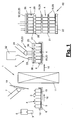
- FIG. 1 shows a schematic representation of a handling device (2) in a system (1).
- the plant (1) can be, for example, a bottle treatment plant in which new plastic bottles (3), in particular PET bottles, are produced and packaged.
- the empty bottles can also be filled and labeled with fluids, eg drinks.
- the bottle treatment plant (1) on the input side to a bottle maker, which is not shown for clarity.
- the bottles are transported via a suitable conveying means, eg an air conveyor, to a schematically indicated converter (6) which grips the bottles (3) individually or in rows and converts them to a carrier (8) of the handling device (2).
- the bottle maker, the converter (6) and the carrier (8) can, for example, according to the WO 99/55604 A1 or even the WO 00/69760 A1 be educated.
- the converter (6) may alternatively be an unpacker.
- the layer gripping device (23) described below may alternatively be designed as a row gripper and used as a converter (6).
- the carrier (8) has e.g. a trough shape and consists of a support bottom (9) and a side wall (10) on a plurality of carrier sides, wherein the side wall (10) is preferably arranged circumferentially.
- the carrier (8) can be arranged a conveyor (16) for its transport. If necessary, the carriers (8) can circulate in the system (1) or be reversibly moved.
- Part of the system (1) and possibly the handling device (2) can also be a bearing (11) for a plurality of carriers (8).
- the carriers (8) can circulate within the system (1) or the handling device (2).
- the bearing (11) can serve as a buffer point for the short-term inclusion of multiple carriers or trays (8). It can also be designed as a shelf storage or the like. With higher capacity. in the Bearing (11), which may be present several times, empty and / or filled bottles (3) can be stored.
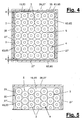
- FIGS. 4 and 5 show in a plan view different layer patterns.
- the rows of bottles are arranged in a regular matrix with straight rows in several rows along and across each other.
- the rows of bottles are mutually gaped and vernestet, with one bottle (3) in each of the two bottles (3) formed in the other row gusset dips.
- gaps (5) can arise between the bottles (3).
- These intermediate spaces (5) may be advantageous for the handling of the bottle layer (4) described below with a layer grasping device (23) and may be at least partially retained.
- guide means possibly entrained, e.g. a grid or the like are used for the bottles (3) in the intermediate spaces (5), but these are preferably not completely filled.
- the bottles (3) may be densely packed in the ply (4), the interspaces (5) being reduced in size.
- a movable and from the support (8) releasable intermediate bottom (19) may be arranged which rests flat or in places on the support base (9) and on which the fabric layer (4) is arranged.
- the area size of the intermediate bottom (19) essentially corresponds to the area size of the goods or bottle layer (4) and can be completed with the projected envelope edge of the bottle layer (4).
- the intermediate bottom (19) can also be slightly larger be and at one or more edges, preferably circumferentially, project laterally beyond the bottle layer (4).
- the handling device (2) has at least one layer grasping device (23) with which a bottle layer (4) is gripped and handled. This handling can be done in different ways.
- the layer gripping device (23) is designed and used as a palletizer (12).
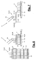
- FIGS. 6 and 7 show a variant in which the layer gripping device (23) as Depalettierer (13) and possibly as a sliding device (14) is formed and used.
- the filled carriers (8) are unloaded with the palletizer (12) or the layer gripping device (23), the goods layer (4) together with the intermediate bottom (19) being gripped and palletized.
- a pallet stack (21) of a plurality of stacked goods or bottle layers (4) together with shelves (19) is formed on a pallet base (22).
- the pallet stack (21) is also referred to in short form as a pallet.
- the intermediate floors (19) form the usual pallets (21) intermediate layers (20).
- an intermediate bottom (19) which is also referred to as a bottom layer and which rests on the pallet base (22).
- the floor or intermediate layers (20) may have a uniform design and size. Subsequently, they are uniformly addressed as intermediate layers (20).
- the handling device (2) can have an insert (7) which can be placed in a suitable position, e.g. on the converter (6), is arranged and in the empty carrier (8) inserts an intermediate bottom (19).
- the shelves (19) or intermediate layers (20) may consist of any suitable material and may have any suitable shape. In the illustrated embodiment, they are formed as a flat plate in a rectangular shape and can be made of cardboard, plastic, metal or the like. Alternatively, they may have contoured surfaces, e.g. recessed receptacles for the bottoms and necks of bottles (3) or other parts of other goods (3).
- the intermediate floors (19) or intermediate layers (20) may alternatively or additionally have edge-side folds for position guidance. You can also have a substantially U- or H-shaped cross-section.
- the intermediate floors (19) or intermediate layers (20) can be largely rigid and wear the fabric layer (4) and support.
- the layer gripping device (23) has in each case a layer gripper (25) and a manipulator (24) for guiding it in the various exemplary embodiments.
- the manipulator (24) can have a plurality of rotary and / or translatory axes in any number and arrangement. It can be designed, for example, as a gantry robot with a plurality of linear axes or as an articulated-arm robot with a plurality of rotary axes.
- a support arm of the manipulator (24) is shown in each case schematically, which at the free end has a rigid or rotatable about at least one axis of rotation hand, which is suitably fixed or detachably connected to the sheet gripper (25).
- the layer gripper (25) is designed as a suction cup.
- the suction bell (25) engages in the various embodiments in each case the goods layer (4) together with the intermediate bottom (19) under the action of a vacuum formed in the interior of the suction bell (25).
- a suction device (32) is provided for its production. It has e.g. a possibly external and stationary vacuum generator, which is connected by means of flexible lines with a connection (33) on the suction bell (25) and which sucks the air located in the bell interior air.
- the vacuum generator (32) can also be arranged on the suction cup (25) and moved along.
- hood which may have a dome in the head area and in the lower region, for example, a circumferentially closed lateral hood wall (27), which leaves a hood opening (28) down.
- the hood wall (27) is formed by a plurality of side walls (27 ').
- the side walls (27 ') are dimensionally stable and consist of a suitably suitable material, for example plastic or metal.
- the dimensional stability can be so great that the side walls (27 ') do not deform or at least do not significantly deform by the negative pressure formed in the hood or bell interior and bulge inwards in contact with the fabric layer (4).
- the side walls (27 ') may be wholly or partially rigid and connected to a frame-like hood wall (27). Alternatively, they can be movable relative to one another, in particular displaceable and / or pivotable, in order to be able to adjust to different hood formats, in particular area sizes and shapes of the hood opening (28) with corresponding setting and control means.
- the side walls (27 ') are preferably airtight and prevent or at least minimize access of outside air through the wall into the hood interior. But it can alternatively also lateral openings, eg in a corner area, be present. In the simple embodiment shown, the side walls (27 ') are rigid and interconnected. They form at the bottom of a same height encircling hood edge (29).
- the suction bell (25) also has an internal and in the hood (26) arranged transversely lying head plate (31) which engages over the fabric layer (4).
- a layer receiving space (44) with the fabric layer (4) is formed below the top plate (31).
- the side hood wall (26) surrounds the layer receiving space (44).
- the suction cup (25) has an exhaust (39), which can be designed differently.
- a suction chamber (43) is formed above the top plate (31) .
- the suction (39) evacuates the layer receiving space (44) and generates here a negative pressure with which the fabric layer (4) and the intermediate bottom (19) or the intermediate layer (20) are sucked in and lifted.
- the head plate (31) can be permeable to air.
- the top plate (31) is e.g. formed as a grid or as a perforated plate with suction openings (40) and can flow the sucked air flow from the layer receiving space (44) to the suction chamber (43) and further to the terminal (33).
- the suction openings (40) can be the same size. Their size may alternatively vary as a whole or locally to realize different suction effects, which may also be locally different.
- the top plate (31) is in the embodiment of Figure 2,3 and 10.11 rigidly arranged in the hood (26). It covers the fabric layer (4) and the layer receiving space (44) and can reach up to the lateral hood wall (27).
- the head plate (31) arranged vertically adjustable and can be raised and lowered in the hood interior with a corresponding adjusting device (not shown), which has a controlled drive. This flexibility is indicated by arrows in FIG. 9 symbolizes.
- the suction cup (25) engages the fabric layer (4) together with an underlying movable bottom (19,20) with a negative pressure generated by suction, which is lower than the external ambient pressure.
- the fabric layer or bottle layer (4) between the sucked bottom (19,20) and the top plate (31) is held and clamped.
- the suction cup (25) holds the bottom (19,20) with negative pressure, with this also a clamping force for the bottle layer (4) can be created.
- the intermediate bottom (19) or the intermediate layer (20) together with the fabric layer (4) is sucked into the hood interior and raised, wherein the goods or bottle layer (4) abuts on the top plate on the top plate (31).
- the hood opening (28) is larger in this embodiment in its opening area than the area size of the fabric layer (4) and also larger than the area size of the intermediate bottom (19) and the intermediate layer (20).
- Between the hood edge (29) or the side walls (27 ') and the edges of the intermediate bottom (19,20) may be a free space (30) through which air is sucked from the outside, if necessary.
- This gap (30) can be kept so small be that the leakage air does not adversely affect the negative pressure or suction pressure in the hood interior.
- the vacuum generator (32) can be designed for a correspondingly large air flow. In this case, the intake airflows large volume and the pressure difference to the ambient pressure and the power consumption and the size of the vacuum generator (32) may be correspondingly low.
- the side walls (27 ') in the illustrated embodiment of FIGS. 2 and 3 smaller than the opening width of the carrier (8), so that the side walls (27 ') between the fabric layer (4) and the bottom (19) and the lateral support walls (10) can dip.
- Such a training is recommended if the lateral support walls (10) have a significant height.
- the hood (26) can also be placed on the support walls (10) with the insides of the side walls (27 ') and the side support walls (10) substantially in alignment.
- a centering aid can be supportive.
- FIG. 3 shows this intake position.
- the fabric layer (4) has in the layer receiving space on all sides a lateral distance from the hood wall (27), which forms a free space.
- a positioning or centering device (35) can be arranged, for example, on one or more side walls (27 ') and arranged with a suitable 'movable and eg strip-shaped actuator (63,64) laterally against one or more, in particular opposite Pressing edges of the fabric layer (4) and the fabric layer (4) within the hood (26) positioned, eg centered.
- FIG. 4 shows such a centering arrangement.
- the two lateral adjusting or centering elements (63) are extended and laterally guide the fabric layer (4).
- a hood (26) can also be adapted to different formats of product layers (4).
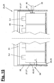
- FIG. 15 illustrates various embodiments of a positioning or centering device (35) in the broken half-section through a suction cup (25) or hood (26).
- the positioning or centering device (35) may consist, for example, according to the left half of the picture of one or more expandable control elements (63), which are designed for example as inflatable tubes.
- FIG. 15 shows the expanded working position with solid lines and the unpressurised or unloaded rest position in dashed form, wherein the distance (a) is shown.
- An expansion and / or increase in volume of variable-shape control elements (63) is also possible in other ways, for example by magnetic forces or electrostatic forces with changeable polarity.
- a continuous or interrupted bar can be arranged with a magnetic or electrostatic polarity and cooperate with an actuator (65), for example, as a generator of an electric or magnetic field with changeable polarity and optionally adjustable field strength or force, eg as a controllable electromagnet, can be formed and the force acting on the bar repulsive forces and possibly attracting forces generated.
- an actuator for example, as a generator of an electric or magnetic field with changeable polarity and optionally adjustable field strength or force, eg as a controllable electromagnet, can be formed and the force acting on the bar repulsive forces and possibly attracting forces generated.
- the positioning or centering device (35) may alternatively have inwardly movable strip-shaped adjusting elements (64) with a suitable mechanical actuator (65).
- the right half of FIG. 15 shows this arrangement.
- the adjusting elements (64) can be, for example, rigid or at least locally deformable clamping bars or the like.
- An actuator (65) may be formed, for example, as a cylinder, as an electric spindle, rack or scissor drive or the like.
- the positioning or centering device (35), in particular its (e) actuator (s) (65) can be controlled or regulated.
- Control is e.g. over the way and / or over the force, in particular the reaction force generated by the fabric layer (4) upon contact, possible.
- a measured value acquisition of a suitable control variable is e.g. by means of a pressure measurement, force measurement, distance or distance measurement, current or charge measurement or the like. Possible.
- a sensor (34) can be arranged in the hood interior or layer receiving space (44), which measures the pressure prevailing in the hood interior and which can be in communication with a control of the suction device (32).
- the controller may have a regulation for the vacuum generator (32), so that the hood internal pressure can be set to default values and optionally regulated.
- the hood internal pressure can be controlled or regulated to different values.
- the hood internal pressure is compared with the ambient pressure in a predetermined course, e.g. in a ramp, reduced, so that the suction and lifting of the bottle layer (4) and the bottom (19,20) takes place in a smooth movement.
- sucking air is sucked not only from the interior of the empty bottles (3), but also from the spaces (5), wherein on the bottles (3) inside and outside substantially the same pressure is applied and the bottle walls retain their shape.
- the inner pressure of the hood (26) can be gradually increased again, the fabric layer (4) and the bottom (19,20) turn in a smooth movement be lowered.
- the soft movements prevent negative mechanical influences on the fabric layer (4) and the bottles (3), which thereby retain their predetermined position and prevented from falling over or other undesirable changes in position.
- the centering device (35) can be loosened or possibly also deactivated.
- the suction cup (25) can transport the sucked product layer (4) and deliver it again at any point. During transport, the centering device (35) can be activated.
- a delivery of the goods or bottle layer (4) can eg FIG. 1 take place at a palletizing station (60).
- the hood edge (29) projects downwards a little above the sucked bottom (19,20).
- This supernatant can be used as a centering and also serves when slipping over the pallet base (22) or on an already palletized layer (4) as a limitation for sucked air leakage.
- the intermediate bottom (19) or the intermediate layer (20) can be placed directly on the bottom goods or bottle layer (4) in the stack (21). be put on.
- the floor (19, 20) can be kept floating at some distance above the already palletized fabric layer (4) by means of the suction bell (25), the vacuum in the hood (26) subsequently being gradually reduced, whereby the floor (19, FIG. 20) and the goods or bottle layer (4) is lowered until it rests on the palletizing stack (21).
- the suction cup (25) can be lifted from the settled goods or bottle layer (4) and moved to the loading point for receiving a new product layer (4).
- Figure 8,9 show a variant of Saugglöcke (25), in the hood opening is greater than the base of the goods or bottle layer (4) and can overlap this laterally.
- the intermediate bottom (19) or the intermediate layer (20) in the surface is larger than the hood opening (28), so that here again inserted between the side support walls (10) Habe (26) with its lower hood edge (29 ) gets up on the laterally over the layer (4) protruding bottom edge regions.
- negative pressure in the hood (26) of the bottom (19,20) against the hood edge (29) is pressed and held.
- the top plate (31) is lowered in this case.
- the lowering can be done so far until the top plate (31) rests on the top layer, here the bottle necks. In this position, the top plate (31) is fixed.
- the negative pressure applied holds the fabric layer (4), which is held by the bottom sucked on the bottom (19,20) down and clamped upwards from the top plate (31).
- a positioning and centering device (35) and a sensor (34) in the hood (26) may be arranged.
- the floor (19, 20) may be placed in the aforementioned manner on a ground, e.g. the top of the top pallet layer, be placed directly. It can alternatively be kept at a small vertical distance and lowered by gradual reduction of the hood vacuum together with the position (4).
- FIGS. 6 and 7 show a Depalettierer (13), with a pallet stack (21) is dismantled and unloaded.
- the suction cup (25) may have the same configuration as in the embodiments described above and is put over the top layer (4) for depalletizing, wherein it can overlap the intermediate layer (20) or can stand up on the intermediate layer (20).
- FIG. 6 shows an embodiment of the above-described design of FIGS. 2 and 3 equivalent.
- the layer gripping device (23) sucks the goods or bottle layer (4) together with the intermediate layer (20) and transports them, while maintaining the suction pressure or negative pressure, up to a stationary or non-stationary delivery point, e.g. may be formed on a conveyor (17). These are e.g. around an intermittent conveyor, e.g. a belt conveyor.
- the goods or bottle layer (4) is deposited in the manner described above together with the intermediate layer (20) on the conveyor (17) and can then be transported on.
- FIGS. 6 and 7 illustrate a further variant in which the layer gripping device (23) is also designed as a sliding device (14), which allows separation of the goods or bottle layer (4) of the intermediate layer (20) at the delivery point.
- a holding device (18) is arranged at the delivery point, which is arranged below the conveyor (17), for example.
- the holding device (18) acts on the intermediate layer (20) and hold on to it.
- the holding device (18) can be designed for this purpose in any suitable manner, for example as a suction device.
- the suction cup (25) can have an additional function as a layer slide (15). If it is released after pressure equalization from the settled position (4), it can according to FIG. 7 moved behind the layer (4) and lowered again, wherein in a subsequent forward movement, the layer (4) through the rigid side walls (27 ') of the hood (26) from the detained bottom (19,20) deported and discharged, for example a subsequent further conveyor (17) for removing the layer (4).
- a separation of the layer (4) into individual rows or individual bottles or goods (3) take place.
- the empty intermediate floor (19) or the intermediate layer (20) can be disposed of in a suitable manner, for example, it is again taken up with the suction cup (25) and transported away. It can be dispensed on a stack or the like. It can alternatively be put back in a standing support (8).
- the suction cup (25) engages in each case a complete goods or bottle layer (4), wherein also the intermediate bottom (19) or the intermediate layer (20) receives a complete bottle position.
- the layer size may correspond to the receiving surface of a carrier (8) or a pallet stack (21).
- the above-described layer (4) may be a partial layer.
- the area size of a partial layer corresponds to the size of a pallet layer, wherein the carrier (8) has an oversize and can accommodate two or more such partial layers side by side. Accordingly, each partial layer also has its own intermediate bottom (19) or its intermediate layer (20).
- the carrier size is smaller than a pallet layer and insofar forms a partial position.
- Several such partial layers can be assembled side by side to form a pallet and palletized.
- depalletizing works in the same way.
- the floor size is adapted to the partial layer size.
- the term used in the embodiments of the product layer (4) also refers to such partial layers.
- mixed containers are produced in the pallet.
- This is e.g. for display pallets of advantage, which should present in each of their piled layers (4) one or more goods, especially bottles (3) of different varieties, such as different drinks, for sale and direct removal for customers.
- Such display pallets form at the point of sale, e.g. in a supermarket, the sales pile and replace a shelf.
- Such mixed containers in the pallet layers are also referred to as Rainbow containers.
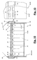
- FIGS. 12 and 13 show a variant of the layer gripping device (23) and the layer gripper or the suction cup (25) and the suction (39).
- This variant is eg able to receive a layer cover (37) in addition to the goods or bottle layer (4) and the optionally existing intermediate bottom (19, 20) and to form a gripping device (36) for this purpose.
- the hood opening (28) is also larger than the layer cover (37).
- the layer cover (37) may consist, for example, of an intermediate layer (20) and a cover (38) arranged thereon and lies on the fabric layer (4).
- the lid (38) may be formed as a top frame and as a narrow peripheral frame, which can serve to support a Stapelumreifung and the outside flush with the pallet contour. In the middle of the top frame (38) has a large opening, which may optionally be arranged stiffening struts.
- the shown layer gripping device (23) can also be used without such or other layer cover (37). It can also be used with a layer cover (37) and without a bottom or intermediate layer (19,20).
- the suction bell (25) can be formed as in the embodiments described above and be provided with a top plate (31) which has one or more suction openings (40) at least in the interior for the passage of air from the layer receiving space (44) into the suction chamber (43). having.
- the connection (33) for the vacuum generator (32) can also be arranged here on the dome or on the suction chamber (43) of the hood (26).
- the size adjustments of the hood opening (28) on the size of the layer (4) and the intermediate bottom (19) can be the same as in the variants of Figure 2,3 and 8.9 be.
- the suction (39) of the gripping device (36) or sheet gripping device (23) in FIGS. 12 and 13 a suction opening (41) in the lateral hood wall (27), which is located in the region of the layer receiving space (44) and opens here and can be acted upon from the outside with negative pressure.
- the suction opening (41) can be present multiple times and can be located on one or more side walls (27 '). Air can also be sucked out of the layer receiving space (44) via the suction opening (s) (41) and the layer receiving space (44) evacuated.
- the suction channel (46) starts from the suction opening or openings (41), leading out of the hood interior, out past a wall area (48) of the hood wall (27) and then to the suction space (43) with a mouth (47) ) connected.
- the suction channel (46) is formed, for example, by a convex cap (45) placed on the outside, which covers the wall openings (41, 47) and is connected, for example screwed, to the hood wall (27).
- the lateral bypass (42) on the hood (26) may be disposed on one or more side walls (27 '). In particular, it can surround the hood (26) in an annular manner.
- the suction opening (s) (41) and the mouth openings (47) can lie one above the other and be distanced from the web-like wall area (48). They can each lie in at least one row at a distance in Hauben peripheral vision in a row and can in particular have an elongated shape.
- a lying on the bottle layer (4) layer cover (37) comes when priming the fabric layer (4) into abutment with the here preferably stationary top plate (31) and covers the suction openings (40) down from.
- the one or more suction openings (41) lie at such a distance below the cover plate (31) that they are free when the sheet cover (37) is sucked in.
- the negative pressure prevailing in the suction chamber (43) acts on the bypass (42) further in the layer receiving space (44) and sucks the air located here, whereby the bottle layer (4) and possibly the intermediate bottom (19,20) sucked and in the contact position held on the sheet cover (37).
- the cover plate (31) is located in the height of the wall region (48) and can be fixed here if necessary.
- the top plate (31) solid and impermeable to air, wherein the layer receiving space (44) is evacuated via the bypass (42).
- Another variant provides, instead of or in addition to the top plate (31) a in FIG. 12 dashed lines indicated edge-like abutment stop (49) on the inside of the hood wall (27) to provide against which the ply cover (37) sets.
- the suction (39) shown by arranging a connection (33) on the suction opening (s) (41) in the hood wall (27) and thereby replacing a bypass (42) or possibly to complete.
- the suction opening (s) (41) can be connected to the existing or to an additional vacuum generator (32).
- in such a side suction (39) via one or more suction opening (s) (41) of the suction chamber (43) omitted.
- the bypass (42) may vary and may be disposed within the hood (26), for example.
- a bypass (not shown) can be formed, for example, in the edge region of an air-permeable top plate (31) reaching up to the hood wall (27).
- the top plate (31) may be larger than the suitably centered ply cover (37) on one or more sides, thereby forming one or more peripheral suction areas or suction gaps, where air is blown out of the ply space (44) adjacent the ply cover (37) ) can be sucked.
- the suction openings (40) in the cover plate (31) may be larger than in their inner region.
- An interrupted or otherwise air-permeable stop (49) can also form edge-side suction regions or suction gaps on the hood wall (27).
- FIG. 14 shows a variant of the bottle treatment plant (1) and the handling device (2) of FIG. 1 ,
- the handling device (2) here has a palletizer (12) and / or depalletizer (13), which is designed as a palletizing robot (58).
- the manipulator (24) is designed as a linear robot with multiple linear axes and carries the layer gripping device (23).
- the conveyors (16) are formed in the embodiment shown as reversing conveyors and extend with their preferably linear movement or conveyor track (52) transversely to the longitudinal axis of the palletizing robot (58) and its portal.
- the conveyor (16) can be single-storey or multi-storey, wherein trays (8) are arranged on several floors above one another and movable.
- the conveyor (16) may be structurally designed as a shuttle car.
- each tray conveyor (16) is here associated with a transfer robot (56), which in each case has a gantry robot with several linear axes and a multiaxially movable row gripper (57).
- the one or more Umsetzroboter (56) each extend over one or more conveyor tracks (52) of the tray conveyor (16) in the area of Umsetzroboters (56) have a working and positioning for a carrier (8).
- an insert (7) is arranged, which is designed as a loading robot (54) and which can also operate one or more tray conveyors (16), which have corresponding supply positions for a tray (8) in the robot working area.
- the infeed robot (54) is likewise embodied as a gantry robot with linear axes and has a multiaxially movable gripping tool (55) with which intermediate shelves (19) and / or intermediate layers or cover layers (20) are gripped by a provision and brought to the trays (8) can be.
- the inlay robot (54) can also pick up lids or top frames (38) from a stack and bring them to the carriers (8) and the product layers (4) there.
- the bottles (4) are fed by a conveyor (50) in one or more rows of the handling device (2).
- the transfer robot (56) takes over one or more rows with its row gripper (57) and places them on a provided support (8) into which the deposit robot (54) previously laid an intermediate floor (19).
- the carrier (8) moves into the ready position on the palletizing robot (58), which with its layer gripping device (23) picks up the goods or bottle layer (4) with the intermediate bottom (19) and to the palletizing station (60) transported and there the palette (21) builds.
- the empty carrier (8) moves back to the delivery position on the infeed robot (54) and picks up a new intermediate layer (19), after which it is moved to the ready position on the transfer robot (56) and loaded again with a bottle layer (4).
- the cycle then starts again.
- the tray first moves back to the depositing robot (54), which has a cover layer (20) and possibly a lid or lid Top Frame (38) hangs up. Only then is the tray (8) transported to the palletizing robot (58) and removed from this added to the completion of the pallet stack (21).
- the palletizing robot (58) can operate a plurality of tray conveyors (16) or trays (8) and several palletizing places (60), so that the processing times can be overlapped. If a tray (8) is being loaded with a bottle layer (4), the palletizing robot (58) can unload a meanwhile available other carrier (8) and form a pallet stack (21). A corresponding function results for the converter (6) and the insert (7).
- the pallet shelves (22) are provided by a pallet feeder (59) and brought to the palletizing places (60). This is followed by a conveyor (51) for the pallets (21). This can accommodate several loaded pallets (21) and can also have several possibly interconnected conveyor strands. An intermediate store or buffer (53) for palletized bottles (3) or other goods can hereby be formed on the conveyor (51).
- the handling device (2) can also be used as a depalletizer (13) in the manner described above, with which the returned pallets (21) are depalletized again, the bottles (3) being converted in rows by the converter onto the conveyor device (50).
- the pallet store (53) can be the tray warehouse (11) of FIG. 1 replace or may supplement such a tray warehouse (11) if necessary.
- a buffering or storage function is useful when a bottle maker located in plant 1, eg a blow molding machine (not shown), has a higher production capacity than a filling device (not shown) or has other process times.
- handling device (2) can also otherwise produced bottles (3), eg glass or new glass, supplied in palletized form and depalletized for subsequent filling and separated.
- bottles (3) eg glass or new glass
- an unpacking device (62) can be connected to the pallet conveyor (51).
- filled bottles can be palletized with the handling device (2) shown and stored or transported away after passing through a schematically indicated packaging device (61).
- the suction cup (25) may include other means, e.g. Sealing lips or the like. It can also be changeable to adapt to different shapes and sizes of the product layers (4). It can alternatively be adjustable in itself. For this purpose, for example, in the hood (26) partitions or the like. Be arranged to form smaller hood areas for partial layers. The hood areas can also be sealed off from one another by suction technology and can be individually controlled or regulated.
- the layer gripping device (23) can in a modification of FIG. 1 for unloading the carriers (8) and for delivering the layers (4) to a conveyor or a stationary delivery point. It forms an unloading device. Alternatively, it can also be used for loading carriers (8) with goods or bottle layers (4).
- the layer gripping device (23) can be used to any charge carriers, in particular boxes, lattice boxes, etc. with goods layers (4) together with intermediate layers (20) and possibly a layer cover (37), eg also a box or Box lid, to load and unload.
- a layer cover eg also a box or Box lid
- several product layers (4) can be stacked on top of each other.
- a carrier (8) may have one or more movable side walls (10) facilitating unloading and delivery of the suction cup (25).
- the carrier (8) can in the arrangement of Figure 2,3 and 8.9 for an external air access to the hood edge (29) and under the intermediate floor (19,20) are taken care of.
- the support bottom (9) can also be designed such that outside air can flow in under the intermediate bottom (19, 20) during lifting, for example by the support base (9) having a raised base, spacer ribs, knobs or the like.
- the suction cup (25) can also be held with a small distance above the support bottom (9). It can also have height-adjustable and, for example, telescopic side walls (27 ').
- hood adaptation to different heights of the fabric layer (4).
- hood edge (29) may be arranged a flexible element which deforms during suction to the intermediate bottom (19,20) out and closes the free space (3) and largely seals.
- the handling device (2) shown with the multi-axis converter (6) for row-wise gripping and defined transfer of bottles (3) on the carrier (8) and back has special advantages for the safe handling and management of the bottles (3).
- a carrier transport between a palletizer / depalletizer (12,13), a converter (6) and a depositor (7) the operation can be optimized.
- the layer gripping device (23) can also be used in conjunction with a conventional palletizer or depalletizer without a carrier.
- the goods, in particular bottles (3) can in the usual way be pushed over a row conveyor on a prepared intermediate layer (20) or brought in some other way, wherein gradually the layer (4) is formed.
- a conventional palletizing the use of the gripping device (36) according to the invention of FIGS. 12 and 13 for the common inclusion of a fabric layer (4) with intermediate layer (20) and layer cover (37) of advantage.
- a layer gripper or a suction cup (25) in the execution of FIGS. 2 and 3 in which the hood opening (28) is larger than the goods layer (4) and the intermediate layer (20), wherein the intermediate layer (20) is also imbibed into the hood interior or layer receiving space (44).
- the layer gripper (23) may be designed and arranged independently in their training as a palletizer (12) or as depalletizer (13) or as a sliding device (15) and also as a loader / unloader. It does not have to be part of the handling device (2) or the system (1) described at the beginning.
- the formation of the layer gripping device (23) has an independent inventive meaning.
- the layer gripping device (23) can grasp, transport and handle fabric layers (4) even without bottom or intermediate layer (20).
- the lateral hood wall (27) can also have a shortened height and does not have to extend to the bottom of the fabric layer (4).
- the layer gripping device (23) can also be used for the independent transport of an intermediate layer or bottom layer (20) and / or a layer cover (37) without a fabric layer (4). In this way, for palletizing a bottom layer (20) on the pallet base (22) placed first and then a sheet cover (37) gripped and immediately followed by a product layer (4) without bottom or intermediate layer (20) are picked and palletized. The same applies to depalletizing. On shelves (19) or intermediate layers (20) in carriers (8) and on an insert (7) for this can be dispensed with.
- the positioning or centering device (35) has independent inventive meaning and can also in other layer gripping means (23) with hood undersize compared to a bottom or intermediate layer (20) according to the embodiment of FIGS. 8 and 9 be used.
- the positioning or centering device (35) can also be used in conventional sheet gripping devices with suction cup, for example according to the US documents mentioned above.
- the handling device (2) with supports (8) and a layer gripping means (23) according to the embodiment of FIGS. 8 and 9 with the bottom or intermediate layer (19, 20) which can be sucked onto the hood edge (28), has independent inventive significance.
- a height-adjustable head plate (31) may be present.
Description
Die Erfindung betrifft eine Lagengreifeinrichtung und eine Handhabungseinrichtung für Waren, insbesondere Flaschen, mit den Merkmalen in den Oberbegriffen der selbstständigen Ansprüche.The invention relates to a sheet gripping device and a handling device for goods, in particular bottles, having the features in the preambles of the independent claims.
Eine solche Lagengreifeinrichtung ist aus der
Die
Aus der Praxis kennt man auch haubenlose Lagengreifer mit einzelnen Saugköpfen, z.B. Saugtulpen, für die einzelnen Waren innerhalb einer Warenreihe oder Warenlage.Also known in practice are hoodless ply grippers with individual suction heads, e.g. Suction tulips, for the individual goods within a series of goods or goods.
Eine Handhabungseinrichtung ist aus der
Es ist Aufgabe der vorliegenden Erfindung, eine bessere Lagengreifertechnik und ggf. eine bessere Handhabung für Warenlagen aufzuzeigen.It is an object of the present invention to provide a better layer gripper technique and possibly better handling for product layers.
Die Erfindung löst diese Aufgabe mit den Merkmalen in den selbstständigen Ansprüchen.
Die beanspruchte Lagengreifeinrichtung hat Vorteile für das sichere Erfassen, Transportieren und Handhaben von Waren, insbesondere Warenlagen, mit Unterdruck gegenüber der Umgebung.The invention solves this problem with the features in the independent claims.
The claimed layer gripping device has advantages for the secure detection, transporting and handling of goods, in particular goods, with negative pressure to the environment.
Die Haube der Saugglocke hat Übermaß gegenüber der Warenlage und einer Boden- oder Zwischenlage und/oder einer Decklage und kann sie zusammen durch die Haubenöffnung ansaugen und bis zur Flaschen-oder Warenanlage an einer haubeninternen Kopfplatte oder einem Anschlag anheben. Der dabei nach unten vorstehende Haubenrand kann bei der Lagenabgabe als Führungs- und Zentriermittel funktionieren. Durch das Einsaugen kann eine Höhenanpassung stattfinden, wobei für unterschiedlich hohe Waren die gleiche Saugglocke eingesetzt werden kann.The hood of the suction cup has excess over the fabric and a bottom or intermediate layer and / or a cover layer and can suck it together through the hood opening and lift up to the bottle or goods system on a hood-headboard or a stop. The hood edge projecting downwards can function as a guiding and centering device when the layer is dispensed. By sucking a height adjustment can take place, for different levels of goods, the same suction cup can be used.
Die Haube führt die Warenlage und den Zwischenboden bzw. die Zwischenlage seitlich und stabilisiert diese. Hierfür können haubenintern eine Positionier- oder Zentriereinrichtung und ggf. eine Sensorik angeordnet sein, wobei letztere den Innendruck der Haube, z.B. im Lagenaufnahmeraum misst und eine Steuerung bzw. Regelung der Saugeinrichtung bzw. des Unterdruckerzeugers ermöglicht.The hood guides the fabric layer and the intermediate bottom or the intermediate layer laterally and stabilizes them. For this purpose, a positioning or centering device and, if necessary, a sensor system can be arranged inside the hood, wherein the latter has the internal pressure of the hood, e.g. measures in the layer receiving space and a control or regulation of the suction device or the vacuum generator allows.
Die beanspruchte Lagengreifeinrichtung hat einen weiten Einsatzbereich und kann eine Warenlage gemeinsame mit einer oder mit mehreren Lagenabdeckungen an der Oberseite und/oder der Unterseite greifen, transportieren oder handhaben, insbesondere mit einer Decklage oder mit einer Bodenlage bzw. Zwischenlage oder mit einer Decklage und mit einer Bodenlage bzw. Zwischenlage. Dies kann einen Palettier- oder Depalettierprozess vereinfachen und beschleunigen. Die Warenlage kann zusammen mit einer Decklage und/oder mit einer Bodenlage bzw. Zwischenlage in den Haubeninnenraum gesaugt und mit der Saugglocke aufgenommen werden.The claimed layer gripping device has a wide range of use and can grip, transport or handle a fabric layer common with one or more layer covers on the top and / or bottom, in particular with a top layer or with a bottom layer or liner or with a top layer and with a Ground layer or intermediate layer. This can simplify and speed up a palletizing or depalletizing process. The fabric layer can be sucked together with a top layer and / or with a bottom layer or intermediate layer in the hood interior and recorded with the suction cup.
Die beanspruchte Lagengreifeinrichtung kann als Palettierer und/oder als Depalettierer eingesetzt werden. Sie kann ferner als Schiebeeinrichtung fungieren, was insbesondere in Verbindung mit einer Depalettierung Vorteile hat. Beim Depalettieren können die Zwischenlagen mitsamt der Warenlage gegriffen und vom Palettenstapel abgenommen werden. Mithilfe einer Schiebeeinrichtung kann anschließend eine Trennung der Warenlage von der Zwischenlage erfolgen, wobei die Saugglocke die Zusatzfunktion eines Lagenschiebers haben kann. Mit dieser Technik kann das Depalettieren schneller, einfacher und sicherer erfolgen, wobei Zwischenlagen separiert und wiederverwendet werden können. Die Zwischenlagen können in einem Kreislauf wandeln und zum Palettieren sowie Depalettieren benutzt werden. Sie können auch in die eingangs genannten Träger rückgeführt werden.The claimed layer gripping device can be used as a palletizer and / or as a depalletizer. It can also act as a sliding device, which in particular in connection with a Depalettierung Has advantages. When depalletizing the intermediate layers can be gripped together with the goods and removed from the pallet stack. By means of a sliding device can then be carried out a separation of the fabric layer of the intermediate layer, wherein the suction cup can have the additional function of a ply slide. With this technique, depalletizing can be faster, easier and safer, separating and reusing liners. The intermediate layers can be converted in a cycle and used for palletizing and depalletizing. You can also be returned to the aforementioned carrier.
Die Lagengreifeinrichtung flexibilisiert die Handhabungstechnik von Waren, insbesondere Flaschen in einer Flaschenbehandlungsanlage und kann bei multifunktionalen Handhabungseinrichtungen eingesetzt werden. Das schnelle und zuverlässige Handhaben von Flaschenlagen, insbesondere Palettieren und Depalettieren erlaubt in Verbindung mit einem Umsetzer und einem Einleger das Palettieren zu Lieferzwecken, aber auch zu Pufferzwecken und auch das Depalettieren zum Einschleusen oder Rückschleusen von zugeführten oder gepufferten Flaschen in den Behandlungskreislauf. Hierfür ist auch die Nutzung von Trägern und deren Fördervorrichtungen vorteilhaft.The layer gripping device makes the handling technology of goods, in particular bottles, more flexible in a bottle treatment plant and can be used in multifunctional handling devices. The rapid and reliable handling of bottle layers, in particular palletizing and depalletizing, in conjunction with a converter and a feeder, permits palletizing for delivery purposes, but also for buffering purposes and also depalletizing for the introduction or return of supplied or buffered bottles into the treatment circuit. For this purpose, the use of carriers and their conveyors is advantageous.
Die Lagengreiftechnik mit Ansaugen einer Bodenlage oder Zwischenlage mitsamt der darauf abgestellten Warenlage hat Vorteile für die sichere Handhabung der Waren. Besondere Vorteile ergeben sich für Flaschen, insbesondere für leere Kunststoffflaschen, die z.B. aus Polyethylenterephthalat, Polyethylen oder dgl. bestehen und die eine begrenzte mechanische Stabilität aufweisen. Die Warenlage und insbesondere die Flaschenlage kann schonend zwischen der Boden- oder Zwischenlage und einer Saugglocke der Lagengreifeinrichtung, insbesondere einer dortigen Kopfplatte, eingespannt und gehalten werden. Durch eine Saugglocke kann ein weitgehend gleicher Druck im Inneren von hohlen Flaschen und in der äußeren Umgebung erzeugt werden, der Deformationen der Flaschen verhindert.The layer gripping technique with suction of a bottom layer or intermediate layer together with the material layer parked thereon has advantages for the safe handling of the goods. Particular advantages arise for bottles, in particular for empty plastic bottles, which consist for example of polyethylene terephthalate, polyethylene or the like and which have a limited mechanical stability. The fabric layer and in particular the bottle layer can be gently between the bottom or intermediate layer and a suction cup of the layer gripping device, in particular a local Headstock, clamped and held. Through a suction cup, a substantially equal pressure can be generated inside hollow bottles and in the external environment, which prevents deformations of the bottles.
Die Anordnung eines lösbaren Zwischenbodens in einem Träger und das Abstellen einer Warenlage, insbesondere einer Flaschenlage, auf diesem Zwischenboden im Träger hat den Vorteil, dass die Warenlage mit einer Saugglocke schnell, schonend und exakt gegriffen und gehandhabt werden kann, wobei der Zwischenboden mitgenommen wird und zum Abstützen der Warenlage nach unten innerhalb der Saugglocke dient. Der Zwischenboden kann im Falle einer Palettierung dann gleich auch eine Zwischenlage im Palettenstapel bilden. Ein Träger erleichtert das Führen und Kommissionieren der Waren bzw. Flaschen und kann auch zu Lagerzwecken dienen. Eine Lagerung oder Pufferung von Waren bzw. Flaschen kann alternativ über ein Palettieren und Stauen mehrerer Paletten erfolgen.The arrangement of a releasable intermediate floor in a carrier and the parking of a fabric layer, especially a bottle layer, on this shelf in the carrier has the advantage that the fabric can be handled and handled quickly, gently and accurately with a suction cup, the false floor is taken and serves to support the goods position down inside the suction cup. The intermediate floor can then form an intermediate layer in the pallet stack in case of palletizing. A carrier facilitates the guiding and picking of the goods or bottles and can also serve for storage purposes. Storage or buffering of goods or bottles can alternatively be done by palletizing and stowing multiple pallets.
Die Absaugung und die Erzeugung von Unterdruck in einem Lagenaufnahmeraum in der Haube zum Ansaugen und Halten der Warenlage etc. kann auf verschiedene Weise erfolgen. Dies kann von oben und zusätzlich oder alternativ von der Seite durch eine Saugöffnung in der seitlichen Haubenwand geschehen. Hierfür ist erfindungsgemäß ein seitlicher externer oder interner Bypass vorgesehen. Die Seitenabsaugung ist insbesondere günstig, wenn sich auf der Warenlage eine Lagenabdeckung befindet, wobei beide sicher eingesaugt und gehalten werden können. Die Seitenabsaugung hat aber auch Vorteile für die Führung der Waren in der Warenlage. Sie sichert den Lagenverbund und vermeidet ein unkontrolliertes Hochspringen einzelner Waren, insbesondere Flaschen, in der Warenlage.The suction and the generation of negative pressure in a layer receiving space in the hood for sucking and holding the fabric layer, etc. can be done in various ways. This can be done from above and additionally or alternatively from the side through a suction opening in the lateral hood wall. For this purpose, a lateral external or internal bypass is provided according to the invention. The Seitenabsaugung is particularly favorable when there is a ply cover on the fabric, both of which can be safely sucked in and held. The side extraction but also has advantages for the management of goods in the warehouse. It secures the layer network and avoids an uncontrolled jump up of individual goods, especially bottles, in the goods situation.
In den Unteransprüchen sind weitere vorteilhafte Ausgestaltungen der Erfindung angegeben.In the subclaims further advantageous embodiments of the invention are given.
Die Erfindung ist in den Zeichnungen beispielhaft und schematisch dargestellt. Im Einzelnen zeigen:
- Figur 1:
- eine Schemadarstellung einer Handhabungseinrichtung in einer Flaschenbehandlungsanlage,
Figur 2 und 3:- eine schematische Querschnittsdarstellung durch eine Saugglocke in verschiedenen Betriebsstellungen,
Figur 4 und 5:- schematische und teilweise abgebrochene Längsschnitte durch eine Saugglocke mit Draufsicht auf die Warenlage in verschiedenen Warenpositionen,
- Figur 6 und 7:
- eine schematische Seitenansicht einer Lagengreifeinrichtung in der Funktion als Depalettierer und als Schiebeeinrichtung in verschiedenen Betriebsstellungen,
Figur 8 und 9:- eine Variante der Saugglocke zu
Figur 2 , Figur 10 und 11:- eine Saugglocke in teilweise aufgebrochener perspektivischer Ansicht und Seitenansicht,
- Figur 12:
- eine Variante eine Lagengreifeinrichtung in geschnittener Seitenansicht
- Figur 13:
- eine geklappte und abgebrochene Ansicht zu
Figur 12 , - Figur 14:
- eine Variante einer Handhabungseinrichtung in einer Flaschenbehandlungsanlage und
- Figur 15:
- eine Positionier- und Zentriereinrichtung.
- FIG. 1:
- a schematic representation of a handling device in a bottle treatment plant,
- FIGS. 2 and 3:
- a schematic cross-sectional view through a suction cup in different operating positions,
- FIGS. 4 and 5:
- schematic and partially broken longitudinal sections through a suction cup with a plan view of the goods in different goods positions,
- FIGS. 6 and 7:
- a schematic side view of a layer gripping device in the function of a depalletizer and as a sliding device in different operating positions,
- FIGS. 8 and 9:
- a variant of the suction cup too
FIG. 2 . - FIGS. 10 and 11:
- a suction cup in a partially broken perspective view and side view,
- FIG. 12:
- a variant of a layer gripping device in a sectional side view
- FIG. 13:
- a folded and broken view too
FIG. 12 . - FIG. 14:
- a variant of a handling device in a bottle treatment plant and
- FIG. 15:
- a positioning and centering device.
Die Erfindung betrifft eine Lagengreifeinrichtung (23) zum Handhaben von Waren (3), insbesondere Flaschen. Die Erfindung betrifft ferner eine Handhabungseinrichtung (2) für Waren (3). Außerdem betrifft die Erfindung die jeweils zugehörigen Handhabungsverfahren sowie eine mit einer Handhabungseinrichtung (2) ausgerüstete Anlage (1).The invention relates to a layer grasping device (23) for handling goods (3), in particular bottles. The invention further relates to a handling device (2) for goods (3). In addition, the invention relates to the respectively associated handling methods and to a handling device (2) equipped system (1).
Die Waren (3) bilden das Lagengut und können von beliebiger Art, Zahl und Größe sein. Es handelt sich vorzugsweise um Flaschen oder um andere Hohlkörper. Dies können leere oder gefüllte Flaschen sein. Die Flaschen können auch aus einem beliebig geeigneten Material, z.B. Glas, Kunststoff oder Verbundmaterialien bestehen. Im gezeigten und bevorzugten Ausführungsbeispiel werden leere Kunststoffflaschen gehandhabt, die z.B. aus Polyethylenterephthalat (nachfolgend abgekürzt PET) bestehen und die eine dünne, mechanisch labile Wandung haben. Derartige PET-Flaschen sind z.B. zur Einmalverwendung vorgesehen und werden recycelt. In einer anderen Variante können die PET-Flaschen (3) eine dickere Wandung haben und als Pfandflaschen für eine Mehrfachverwendung vorgesehen sein. In weiterer Abwandlung können die Waren (3) andere, insbesondere quaderförmige Behälter, z.B. Schachteln, Dosen oder dgl. aus Karton, Metall oder dgl. sein.The goods (3) form the Lagengut and can be of any kind, number and size. They are preferably bottles or other hollow bodies. These can be empty or filled bottles. The bottles may also be made of any suitable material, e.g. Glass, plastic or composite materials. In the illustrated and preferred embodiment, empty plastic bottles are handled, e.g. of polyethylene terephthalate (hereinafter abbreviated to PET) and have a thin, mechanically labile wall. Such PET bottles are e.g. for single use and are recycled. In another variant, the PET bottles (3) may have a thicker wall and be provided as returnable bottles for multiple use. In a further modification, the goods (3) may be other, in particular parallelepipedic, e.g. Boxes, cans or the like. From cardboard, metal or the like. Be.
In weiterer Abwandlung ist es möglich, der Flaschenbehandlungsanlage (1) anderweitig hergestellte neue Flaschen (3) oder ggf. Altflaschen im Wiederverwertungskreislauf zuzuführen.In a further modification, it is possible to supply the bottle treatment plant (1) with other new bottles (3) or otherwise used bottles in the recycling loop.
In der Variante von
Der Träger (8) hat z.B. eine Wannenform und besteht aus einem Trägerboden (9) und einer Seitenwand (10) an mehreren Trägerseiten, wobei die Seitenwand (10) vorzugsweise umlaufend angeordnet ist.The carrier (8) has e.g. a trough shape and consists of a support bottom (9) and a side wall (10) on a plurality of carrier sides, wherein the side wall (10) is preferably arranged circumferentially.
Für den Träger (8) kann eine Fördereinrichtung (16) zu dessen Transport angeordnet sein. Die Träger (8) können ggf. in der Anlage (1) im Umlauf zirkulieren oder reversierend bewegt werden. Bestandteil der Anlage (1) und ggf. der Handhabungseinrichtung (2) kann ferner ein Lager (11) für mehrere Träger (8) sein. Die Träger (8) können innerhalb der Anlage (1) bzw. der Handhabungseinrichtung (2) im Kreislauf zirkulieren. Das Lager (11) kann als Pufferstelle zur kurzzeitigen Aufnahme mehrerer Träger oder Trays (8) dienen. Es kann auch als Regallager oder dgl. mit höherer Aufnahmekapazität ausgebildet sein. Im Lager (11), das ggf. mehrfach vorhanden ist, können leere und/oder befüllte Flaschen (3) gelagert werden.For the carrier (8) can be arranged a conveyor (16) for its transport. If necessary, the carriers (8) can circulate in the system (1) or be reversibly moved. Part of the system (1) and possibly the handling device (2) can also be a bearing (11) for a plurality of carriers (8). The carriers (8) can circulate within the system (1) or the handling device (2). The bearing (11) can serve as a buffer point for the short-term inclusion of multiple carriers or trays (8). It can also be designed as a shelf storage or the like. With higher capacity. in the Bearing (11), which may be present several times, empty and / or filled bottles (3) can be stored.
Der Umsetzer (6) bildet auf dem Träger (8) eine Warenlage oder Flaschenlage (4), indem die Flaschen (3) einzeln oder reihenweise nebeneinander gestellt werden.
In beiden Lagenmustern können zwischen den Flaschen (3) Zwischenräume (5) entstehen. Diese Zwischenräume (5) können für die nachfolgend beschriebene Handhabung der Flaschenlage (4) mit einer Lagengreifeinrichtung (23) von Vorteil sein und können zumindest teilweise beibehalten werden. Unter Umständen können ggf. mitgeführte Führungsmittel, z.B. ein Gitter oder dgl. für die Flaschen (3) in die Zwischenräume (5) eingesetzt werden, wobei diese aber vorzugsweise nicht vollständig ausgefüllt werden. Alternativ können die Flaschen (3) in der Lage (4) dicht gepackt sein, wobei die Zwischenräume (5) verkleinert sind.In both layer patterns, gaps (5) can arise between the bottles (3). These intermediate spaces (5) may be advantageous for the handling of the bottle layer (4) described below with a layer grasping device (23) and may be at least partially retained. In some circumstances, guide means possibly entrained, e.g. a grid or the like are used for the bottles (3) in the intermediate spaces (5), but these are preferably not completely filled. Alternatively, the bottles (3) may be densely packed in the ply (4), the interspaces (5) being reduced in size.
Wie
Die Handhabungseinrichtung (2) weist mindestens eine Lagengreifeinrichtung (23) auf, mit der eine Flaschenlage (4) gegriffen und gehandhabt wird. Diese Handhabung kann auf unterschiedliche Weise geschehen. In der Ausführung von
In der Ausführungsform von
Bei dieser Ausführung ist die separate Zufuhr von Zwischenlagen (20) zum Palettierplatz entbehrlich. Die Handhabungseinrichtung (2) kann einen Einleger (7) aufweisen, der an geeigneter Stelle, z.B. am Umsetzer (6), angeordnet ist und der in die leeren Träger (8) einen Zwischenboden (19) einlegt.In this embodiment, the separate supply of intermediate layers (20) to the palletizing is unnecessary. The handling device (2) can have an insert (7) which can be placed in a suitable position, e.g. on the converter (6), is arranged and in the empty carrier (8) inserts an intermediate bottom (19).
Die Zwischenböden (19) oder Zwischenlagen (20) können aus einem beliebig geeigneten Material bestehen und können eine beliebig geeignete Formgebung haben. Im gezeigten Ausführungsbeispiel sind sie als ebene Platten in Rechteckform ausgebildet und können aus Karton, Kunststoff, Metall oder dgl. bestehen. Alternativ können sie konturierte Oberflächen besitzen, die z.B. vertiefte Aufnahmen für die Böden und Hälse von Flaschen (3) oder von anderen Teilen anderer Waren (3) aufweisen. Die Zwischenböden (19) oder Zwischenlagen (20) können alternativ oder zusätzlich randseitige Abkantungen zur Lagenführung aufweisen. Sie können ferner einen im wesentliche U- oder H- förmigen Querschnitt aufweisen. Die Zwischenböden (19) oder Zwischenlagen (20) können weitgehend biegesteif sein und die Warenlage (4) tragen und abstützen.The shelves (19) or intermediate layers (20) may consist of any suitable material and may have any suitable shape. In the illustrated embodiment, they are formed as a flat plate in a rectangular shape and can be made of cardboard, plastic, metal or the like. Alternatively, they may have contoured surfaces, e.g. recessed receptacles for the bottoms and necks of bottles (3) or other parts of other goods (3). The intermediate floors (19) or intermediate layers (20) may alternatively or additionally have edge-side folds for position guidance. You can also have a substantially U- or H-shaped cross-section. The intermediate floors (19) or intermediate layers (20) can be largely rigid and wear the fabric layer (4) and support.
Die Lagengreifeinrichtung (23) weist in den verschiedenen Ausführungsbeispielen jeweils einen Lagengreifer (25) und einen Manipulator (24) zu dessen Führung auf. Der Manipulator (24) kann mehrere rotatorische und/oder translatorische Achsen in beliebiger Zahl und Anordnung aufweisen. Er kann z.B. als Portalroboter mit mehreren Linearachsen oder als Gelenkarmroboter mit mehreren rotatorischen Achsen ausgebildet sein. In den Zeichnungen ist jeweils schematisch ein Tragarm des Manipulators (24) dargestellt, der am freien Ende eine starre oder um mindestens eine Rotationsachse drehbewegliche Hand aufweist, die in geeigneter Weise fest oder lösbar mit dem Lagengreifer (25) verbunden ist.The layer gripping device (23) has in each case a layer gripper (25) and a manipulator (24) for guiding it in the various exemplary embodiments. The manipulator (24) can have a plurality of rotary and / or translatory axes in any number and arrangement. It can be designed, for example, as a gantry robot with a plurality of linear axes or as an articulated-arm robot with a plurality of rotary axes. In the drawings, a support arm of the manipulator (24) is shown in each case schematically, which at the free end has a rigid or rotatable about at least one axis of rotation hand, which is suitably fixed or detachably connected to the sheet gripper (25).
Der Lagengreifer (25) ist als Saugglocke ausgebildet. Die Saugglocke (25) greift in den verschiedenen Ausführungsbeispielen jeweils die Warenlage (4) mitsamt dem Zwischenboden (19) unter Einwirkung eines im Innenraum der Saugglocke (25) gebildeten Unterdrucks. Für dessen Erzeugung ist eine Saugeinrichtung (32) vorgesehen. Sie weist z.B. einen ggf. externen und stationären Unterdruckerzeuger auf, der mittels flexibler Leitungen mit einem Anschluss (33) an der Saugglocke (25) verbunden ist und der die im Glockeninnenraum befindliche Luft absaugt. Der Unterdruckerzeuger (32) kann auch an der Saugglocke (25) angeordnet sein und mitbewegt werden.The layer gripper (25) is designed as a suction cup. The suction bell (25) engages in the various embodiments in each case the goods layer (4) together with the intermediate bottom (19) under the action of a vacuum formed in the interior of the suction bell (25). For its production, a suction device (32) is provided. It has e.g. a possibly external and stationary vacuum generator, which is connected by means of flexible lines with a connection (33) on the suction bell (25) and which sucks the air located in the bell interior air. The vacuum generator (32) can also be arranged on the suction cup (25) and moved along.
Wie
Die Seitenwände (27') sind formstabil und bestehen aus einem entsprechend geeigneten Material, z.B. Kunststoff oder Metall. Die Formstabilität kann so groß sein, dass die Seitenwände (27') sich nicht oder zumindest nicht wesentlich durch den im Hauben- oder Glockeninnenraum gebildeten Unterdruck verformen und nach innen in Kontakt zur Warenlage (4) hin wölben. Die Seitenwände (27') können insgesamt oder bereichsweise starr sein und miteinander zu einer rahmenartigen Haubenwandung (27) verbunden sein. Sie können alternativ relativ zueinander beweglich, insbesondere verschiebbar und/oder schwenkbar sein, um sich auf unterschiedliche Haubenformate, insbesondere Flächengrößen und Formen der Haubenöffnung (28) mit entsprechenden Stell- und Steuermitteln einstellen zu lassen. Die Seitenwände (27') sind vorzugsweise luftdicht und verhindern oder zumindest minimieren einen Zutritt von Außenluft durch die Wand in den Haubeninnenraum. Es können aber alternativ auch seitliche Öffnungen, z.B. in einem Eckbereich, vorhanden sein. In der gezeigten einfachen Ausführungsform sind die Seitenwände (27') starr ausgebildet und miteinander verbunden. Sie bilden an der Unterseite einen in gleicher Höhe umlaufenden Haubenrand (29).The side walls (27 ') are dimensionally stable and consist of a suitably suitable material, for example plastic or metal. The dimensional stability can be so great that the side walls (27 ') do not deform or at least do not significantly deform by the negative pressure formed in the hood or bell interior and bulge inwards in contact with the fabric layer (4). The side walls (27 ') may be wholly or partially rigid and connected to a frame-like hood wall (27). Alternatively, they can be movable relative to one another, in particular displaceable and / or pivotable, in order to be able to adjust to different hood formats, in particular area sizes and shapes of the hood opening (28) with corresponding setting and control means. The side walls (27 ') are preferably airtight and prevent or at least minimize access of outside air through the wall into the hood interior. But it can alternatively also lateral openings, eg in a corner area, be present. In the simple embodiment shown, the side walls (27 ') are rigid and interconnected. They form at the bottom of a same height encircling hood edge (29).
Die Saugglocke (25) weist ferner eine interne und in der Haube (26) quer liegend angeordnete Kopfplatte (31) auf, welche die Warenlage (4) übergreift. In der Haube (26) wird unterhalb der Kopfplatte (31) ein Lagenaufnahmeraum (44) mit der Warenlage (4) gebildet. Die seitliche Haubenwand (26) umgibt den Lagenaufnahmeraum (44). Die Saugglocke (25) weist eine Absaugung (39) auf, die unterschiedlich ausgebildet sein kann. In der gezeigten Ausführungsform wird z.B. oberhalb der Kopfplatte (31) ein Saugraum (43) gebildet. Die Absaugung (39) evakuiert den Lagenaufnahmeraum (44) und erzeugt hier einen Unterdruck, mit dem die Warenlage (4) und der Zwischenboden (19) bzw. die Zwischenlage (20) angesaugt und angehoben werden.The suction bell (25) also has an internal and in the hood (26) arranged transversely lying head plate (31) which engages over the fabric layer (4). In the hood (26) a layer receiving space (44) with the fabric layer (4) is formed below the top plate (31). The side hood wall (26) surrounds the layer receiving space (44). The suction cup (25) has an exhaust (39), which can be designed differently. In the embodiment shown, e.g. above the top plate (31) a suction chamber (43) is formed. The suction (39) evacuates the layer receiving space (44) and generates here a negative pressure with which the fabric layer (4) and the intermediate bottom (19) or the intermediate layer (20) are sucked in and lifted.
Die Kopfplatte (31) kann luftdurchlässig sein. Im gezeigten Ausführungsbeispiel ist die Kopfplatte (31) z.B. als Gitter oder als Lochplatte mit Saugöffnungen (40) ausgebildet und lässt die angesaugte Luftströmung vom Lagenaufnahmeraum (44) zum Saugraum (43) und weiter zum Anschluss (33) durchströmen. Die Saugöffnungen (40) können gleich groß sein. Ihre Größe kann alternativ im Ganzen oder lokal variieren, um unterschiedliche Saugeffekte zu realisieren, die ggf. auch örtlich unterschiedlich sein können.The head plate (31) can be permeable to air. In the embodiment shown, the top plate (31) is e.g. formed as a grid or as a perforated plate with suction openings (40) and can flow the sucked air flow from the layer receiving space (44) to the suction chamber (43) and further to the terminal (33). The suction openings (40) can be the same size. Their size may alternatively vary as a whole or locally to realize different suction effects, which may also be locally different.
Die Kopfplatte (31) ist in der Ausführungsform von
Wie
Für die Saugglocke (25) und deren Greiffunktion gibt es verschiedene Gestaltungsmöglichkeiten, wobei insbesondere
In der Ausführungsform von
Am Außenumfang sind die Seitenwände (27') im gezeigten Ausführungsbeispiel von
Durch den im Haubeninnenraum bzw. Lagenaufnahmeraum (44) aufgebauten Unterdruck werden die Flaschenlage (4) und der Zwischenboden (19) bzw. die Zwischenlage (20) angesaugt und im Haubeninnenraum angehoben.
Die Warenlage (4) hat im Lagenaufnahmeraum an allen Seiten einen seitlichen Abstand von der Haubenwand (27), der einen Freiraum bildet. In der Haube (26), insbesondere im Bereich des Lagenaufnahmeraums (44) und im Freiraum, kann eine Positionier- oder Zentriereinrichtung (35) angeordnet sein, die z.B. an ein oder mehreren Seitenwänden (27') angeordnet ist und die mit einem geeigneten,' beweglichen und z.B. leistenförmigen Stellelement (63,64) seitlich gegen einen oder mehrere, insbesondere gegenüberliegende Ränder der Warenlage (4) drückt und die Warenlage (4) innerhalb der Haube (26) positioniert, z.B. zentriert.
Die Positionier- oder Zentriereinrichtung (35) kann alternativ nach innen bewegliche leistenförmige Stellelemente (64) mit einem geeigneten mechanischen Stellantrieb (65) aufweisen. Die rechte Bildhälfte von
Die Positionier- oder Zentriereinrichtung (35), insbesondere ihr(e) Stellantrieb(e) (65) kann steuerbar oder regelbar sein. Eine Steuerung oder Regelung ist z.B. über den Weg und/oder über die Kraft, insbesondere die von der Warenlage (4) bei Kontakt erzeugte Reaktionskraft, möglich. Eine Messwerterfassung einer geeigneten Steuer- oder Regelgröße ist z.B. mittels einer Druckmessung, Kraftmessung, Abstands- oder Wegmessung, Strom- oder Ladungsmessung oder dgl. möglich.The positioning or centering device (35), in particular its (e) actuator (s) (65) can be controlled or regulated. Control is e.g. over the way and / or over the force, in particular the reaction force generated by the fabric layer (4) upon contact, possible. A measured value acquisition of a suitable control variable is e.g. by means of a pressure measurement, force measurement, distance or distance measurement, current or charge measurement or the like. Possible.
Im Haubeninnenraum oder Lagenaufnahmeraum (44) kann ferner ein Sensor (34) angeordnet sein, der den im Haubeninnenraum herrschenden Druck misst und der mit einer Steuerung der Saugeinrichtung (32) in Verbindung stehen kann. Die Steuerung kann eine Regelung für den Unterdruckerzeuger (32) aufweisen, sodass der Haubeninnendruck auf Vorgabewerte einstellbar und ggf. regelbar ist. Der Haubeninnendruck kann dabei auf unterschiedliche Werte gesteuert oder geregelt werden.Furthermore, a sensor (34) can be arranged in the hood interior or layer receiving space (44), which measures the pressure prevailing in the hood interior and which can be in communication with a control of the suction device (32). The controller may have a regulation for the vacuum generator (32), so that the hood internal pressure can be set to default values and optionally regulated. The hood internal pressure can be controlled or regulated to different values.
Beim Ansaugen der Warenlage (4) und dem Boden (19,20) wird der Haubeninnendruck gegenüber dem Umgebungsdruck in einem vorgegebenen Verlauf, z.B. in einer Rampe, gemindert, sodass das Ansaugen und Anheben der Flaschenlage (4) und des Bodens (19,20) in einer weichen Bewegung erfolgt. Beim Ansaugen wird Luft nicht nur aus dem Innenraum der leeren Flaschen (3), sondern auch aus den Zwischenräumen (5) angesaugt, wobei an den Flaschen (3) innenseitig und außenseitig im wesentlichen der gleiche Druck anliegt und die Flaschenwände ihre Form behalten.When sucking the fabric layer (4) and the bottom (19,20), the hood internal pressure is compared with the ambient pressure in a predetermined course, e.g. in a ramp, reduced, so that the suction and lifting of the bottle layer (4) and the bottom (19,20) takes place in a smooth movement. When sucking air is sucked not only from the interior of the empty bottles (3), but also from the spaces (5), wherein on the bottles (3) inside and outside substantially the same pressure is applied and the bottle walls retain their shape.
Zum Absenken und zur Abgabe der Warenlage (4) und des Bodens (19,20) kann der Innendruck der Haube (26) allmählich wieder erhöht werden, wobei die Warenlage (4) und der Boden (19,20) wiederum in einer weichen Bewegung abgesenkt werden. Die weichen Bewegungen verhindern negative mechanische Einflüsse auf die Warenlage (4) und die Flaschen (3), die dadurch ihre vorgegebene Lage behalten und am Umfallen oder an sonstigen unerwünschten Lageänderungen gehindert werden. Zum Heben und Senken kann die Zentriereinrichtung (35) gelockert oder ggf. auch deaktiviert werden. Die Saugglocke (25) kann die angesaugte Warenlage (4) transportieren und an beliebiger Stelle wieder abgeben. Während des Transports kann die Zentriereinrichtung (35) aktiviert sein.To lower and release the fabric layer (4) and the bottom (19,20), the inner pressure of the hood (26) can be gradually increased again, the fabric layer (4) and the bottom (19,20) turn in a smooth movement be lowered. The soft movements prevent negative mechanical influences on the fabric layer (4) and the bottles (3), which thereby retain their predetermined position and prevented from falling over or other undesirable changes in position. For lifting and lowering the centering device (35) can be loosened or possibly also deactivated. The suction cup (25) can transport the sucked product layer (4) and deliver it again at any point. During transport, the centering device (35) can be activated.
Eine Abgabe der Waren- oder Flaschenlage (4) kann z.B. bei
Zum Absetzen kann der Boden (19,20) in der vorerwähnten Weise auf einem Untergrund, z.B. der Oberseite der obersten Palettenlage, direkt aufgesetzt werden. Er kann alternativ mit geringem Höhenabstand gehalten und durch allmählichen Abbau des Haubenunterdrucks mitsamt der Lage (4) abgesenkt werden.For settling, the floor (19, 20) may be placed in the aforementioned manner on a ground, e.g. the top of the top pallet layer, be placed directly. It can alternatively be kept at a small vertical distance and lowered by gradual reduction of the hood vacuum together with the position (4).
Die Lagengreifeinrichtung (23) saugt die Waren- oder Flaschenlage (4) mitsamt der Zwischenlage (20) an und transportiert sie unter Aufrechterhaltung des Saugdrucks oder Unterdrucks bis zu einer stationären oder instationären Abgabestelle, die z.B. an einer Fördereinrichtung (17) gebildet sein kann. Hierbei handelt es sich z.B. um einen intermittierend arbeitenden Förderer, z.B. einen Bandförderer. Die Waren- oder Flaschenlage (4) wird in der vorbeschriebenen Weise mitsamt der Zwischenlage (20) auf der Fördereinrichtung (17) abgesetzt und kann dann weitertransportiert werden.The layer gripping device (23) sucks the goods or bottle layer (4) together with the intermediate layer (20) and transports them, while maintaining the suction pressure or negative pressure, up to a stationary or non-stationary delivery point, e.g. may be formed on a conveyor (17). These are e.g. around an intermittent conveyor, e.g. a belt conveyor. The goods or bottle layer (4) is deposited in the manner described above together with the intermediate layer (20) on the conveyor (17) and can then be transported on.
Die Saugglocke (25) kann eine Zusatzfunktion als Lagenschieber (15) haben. Wenn sie nach Druckausgleich von der abgesetzten Lage (4) gelöst wird, kann sie gemäß
In den gezeigten Ausführungsbeispielen greift die Saugglocke (25) jeweils eine komplette Waren- oder Flaschenlage (4), wobei auch der Zwischenboden (19) bzw. die Zwischenlage (20) eine komplette Flaschenlage aufnimmt. Die Lagengröße kann dabei der Aufnahmefläche eines Trägers (8) bzw. eines Palettenstapels (21) entsprechen. In einer abgewandelten Ausführungsform kann die vorbeschriebene Lage (4) eine Teillage sein. In diesem Fall entspricht z.B. die Flächengröße einer Teillage der Größe einer Palettenlage, wobei der Träger (8) eine Übergröße hat und zwei oder mehr solcher Teillagen nebeneinander aufnehmen kann. Dementsprechend hat jede Teillage auch ihren eigenen Zwischenboden (19) bzw. ihre Zwischenlage (20). Darüber hinaus ist eine weitere Abwandlung mit umgekehrten Größenverhältnissen möglich, wobei die Trägergröße kleiner als eine Palettenlage und insoweit eine Teillage bildet. Mehrere solcher Teillagen können nebeneinander zu einer Palettenlage zusammengesetzt und palettiert werden. Desgleichen funktioniert auch ein Depalettieren in entsprechender Weise. Auch in diesem Fall ist die Bodengröße an die Teillagengröße angepasst. Daneben kann es weitere Konfigurationen von Teillagenbildung geben. Der in den Ausführungsbeispielen benutzte Begriff der Warenlage (4) bezieht sich auch auf solche Teillagen.In the illustrated embodiments, the suction cup (25) engages in each case a complete goods or bottle layer (4), wherein also the intermediate bottom (19) or the intermediate layer (20) receives a complete bottle position. The layer size may correspond to the receiving surface of a carrier (8) or a pallet stack (21). In a modified embodiment, the above-described layer (4) may be a partial layer. In this case, for example, the area size of a partial layer corresponds to the size of a pallet layer, wherein the carrier (8) has an oversize and can accommodate two or more such partial layers side by side. Accordingly, each partial layer also has its own intermediate bottom (19) or its intermediate layer (20). In addition, a further modification with inverse size ratios is possible, wherein the carrier size is smaller than a pallet layer and insofar forms a partial position. Several such partial layers can be assembled side by side to form a pallet and palletized. Similarly, depalletizing works in the same way. Also in this case the floor size is adapted to the partial layer size. In addition, there may be other configurations of partial sheet formation. The term used in the embodiments of the product layer (4) also refers to such partial layers.
Mit einer Teillagenbildung können z.B. gemischte Gebinde in der Palette hergestellt werden. Dies ist z.B. für Displaypaletten von Vorteil, die in jeder ihrer aufgestapelten Lagen (4) ein oder mehrere Waren, insbesondere Flaschen (3) von unterschiedlichen Sorten, beispielsweise unterschiedlichen Getränken, zum Verkauf und zur direkten Entnahme für Kunden präsentieren sollen. Derartige Displaypaletten bilden an der Verkaufsstelle, z.B. in einem Supermarkt, den Verkaufsstapel und ersetzen ein Regal. Derartige Mischgebinde in den Palettenlagen werden auch als Rainbow-Gebinde bezeichnet.With a partial sheet formation, e.g. mixed containers are produced in the pallet. This is e.g. for display pallets of advantage, which should present in each of their piled layers (4) one or more goods, especially bottles (3) of different varieties, such as different drinks, for sale and direct removal for customers. Such display pallets form at the point of sale, e.g. in a supermarket, the sales pile and replace a shelf. Such mixed containers in the pallet layers are also referred to as Rainbow containers.
Die gezeigte Lagengreifeinrichtung (23) kann auch ohne eine solche oder andere Lagenabdeckung (37) benutzt werden. Sie kann ferner mit einer Lagenabdeckung (37) und ohne einen Boden- oder Zwischenlage (19,20) eingesetzt werden.The shown layer gripping device (23) can also be used without such or other layer cover (37). It can also be used with a layer cover (37) and without a bottom or intermediate layer (19,20).
Die Saugglocke (25) kann wie in den vorbeschriebenen Ausführungsbeispielen ausgebildet und mit einer Kopfplatte (31) versehen sein, welche eine oder mehrere Saugöffnungen (40) zumindest im Innenbereich für den Durchtritt von Luft aus dem Lagenaufnahmeraum (44) in den Saugraum (43) aufweist. Der Anschluss (33) für den Unterdruckerzeuger (32) kann auch hier am Dom bzw. am Saugraum (43) der Haube (26) angeordnet sein. Auch die Größenabstimmungen der Haubenöffnung (28) auf die Größe der Lage (4) und des Zwischenbodens (19) können die gleichen wie in den Varianten von
Im Unterschied zu den vorbeschriebenen Ausführungsbeispielen hat die Absaugung (39) der Greifeinrichtung (36) bzw. Lagengreifeinrichtung (23) in
Zu diesem Zweck ist in der Ausführungsform von
Der seitliche Bypass (42) an der Haube (26) kann an einer oder an mehreren Seitenwänden (27') angeordnet sein. Er kann insbesondere ringartig die Haube (26) umgeben. Die Saugöffnung(en) (41) und die Mündungsöffnungen (47) können übereinander liegen und vom stegartigen Wandbereich (48) distanziert sein. Sie können jeweils in mindestens einer Reihe mit Abstand in Haubenumfangsichtung hintereinander liegen und können insbesondere eine längliche Form haben.The lateral bypass (42) on the hood (26) may be disposed on one or more side walls (27 '). In particular, it can surround the hood (26) in an annular manner. The suction opening (s) (41) and the mouth openings (47) can lie one above the other and be distanced from the web-like wall area (48). They can each lie in at least one row at a distance in Hauben peripheral vision in a row and can in particular have an elongated shape.
Eine auf der Flaschenlage (4) liegende Lagenabdeckung (37) kommt beim Ansaugen der Warenlage (4) in Anschlag mit der hier vorzugsweise stationären Kopfplatte (31) und deckt deren Saugöffnungen (40) nach unten ab. Die ein oder mehreren Saugöffnungen (41) liegen mit einem solchen Abstand unterhalb der Deckplatte (31), dass sie bei angesaugter Lagenabdeckung (37) frei sind. Der im Saugraum (43) herrschende Unterdruck wirkt über den Bypass (42) weiter im Lagenaufnahmeraum (44) und saugt die hier befindliche Luft ab, wodurch die Flaschenlage (4) und ggf. der Zwischenboden (19,20) angesaugt und in der Anlagestellung an der Lagenabdeckung (37) gehalten werden. Die Deckplatte (31) befindet sich in Höhe des Wandbereichs (48) und kann hier ggf. fixiert sein.A lying on the bottle layer (4) layer cover (37) comes when priming the fabric layer (4) into abutment with the here preferably stationary top plate (31) and covers the suction openings (40) down from. The one or more suction openings (41) lie at such a distance below the cover plate (31) that they are free when the sheet cover (37) is sucked in. The negative pressure prevailing in the suction chamber (43) acts on the bypass (42) further in the layer receiving space (44) and sucks the air located here, whereby the bottle layer (4) and possibly the intermediate bottom (19,20) sucked and in the contact position held on the sheet cover (37). The cover plate (31) is located in the height of the wall region (48) and can be fixed here if necessary.
In Abwandung der gezeigten Ausführungsform ist es möglich, die Kopfplatte (31) massiv und luftundurchlässig auszubilden, wobei über den Bypass (42) der Lagenaufnahmeraum (44) evakuiert wird. Eine weitere Variante sieht vor, statt oder zusätzlich zu der Kopfplatte (31) einen in
Ferner kann der Bypass (42) variieren und kann z.B. innerhalb der Haube (26) angeordnet sein. Ein solcher Bypass (nicht dargestellt) kann z.B. im Randbereich einer luftpermeablen und bis zur Haubenwand (27) reichenden Kopfplatte (31) gebildet werden. Die Kopfplatte (31) kann an einer oder mehreren Seiten größer als die in geeigneter Weise zentrierte Lagenabdeckung (37) sein, wodurch ein oder mehrere randseitige Saugbereiche bzw. Saugspalte gebildet werden, an denen neben der Lagenabdeckung (37) Luft aus dem Lagenaufnahmeraum (44) gesaugt werden kann. An diesen zwischen einer oder mehreren Seitenwänden (27') und der Lagenabdeckung (37) gebildeten Rand-Saugbereichen können die Saugöffnungen (40) in der Deckplatte (31) größer als in deren Innenbereich sein. Auch ein unterbrochener oder auf andere Weise luftdurchlässiger Anschlag (49) kann randseitige Saugbereiche bzw. Saugspalte an der Haubenwand (27) bilden. Außerdem können die seitlichen Abstände der Warenlage (4) zu ein oder mehreren Seitenwänden (27') größer als in den gezeigten Ausführungsformen sein, wobei die Positionier- oder Zentriereinrichtung (35) entsprechend angepasst ist.Further, the bypass (42) may vary and may be disposed within the hood (26), for example. Such a bypass (not shown) can be formed, for example, in the edge region of an air-permeable top plate (31) reaching up to the hood wall (27). The top plate (31) may be larger than the suitably centered ply cover (37) on one or more sides, thereby forming one or more peripheral suction areas or suction gaps, where air is blown out of the ply space (44) adjacent the ply cover (37) ) can be sucked. At these edge suction regions formed between one or more side walls (27 ') and the ply cover (37), the suction openings (40) in the cover plate (31) may be larger than in their inner region. An interrupted or otherwise air-permeable stop (49) can also form edge-side suction regions or suction gaps on the hood wall (27). In addition, the lateral distances of the fabric layer (4) to one or more side walls (27 ') greater than in the shown Be embodiments, wherein the positioning or centering device (35) is adjusted accordingly.
Neben dem Palettierroboter (58) sind eine, zwei oder mehr Umsetzer (6) angeordnet, die hier als Umsetzroboter (56) ausgebildet sind. Jedem Tray-Förder (16) ist hier ein Umsetzroboter (56) zugeordnet, der jeweils einen Portalroboter mit mehreren Linearachsen und einen mehrachsig beweglichen Reihengreifer (57) aufweist. Der oder die Umsetzroboter (56) erstrecken sich jeweils über eine oder mehrere Förderbahnen (52) der Tray-Förderer (16), die im Bereich des Umsetzroboters (56) eine Arbeits- und Positionierstelle für einen Träger (8) haben.In addition to the palletizing robot (58), one, two or more converters (6) are arranged, which are designed here as conversion robots (56). Each tray conveyor (16) is here associated with a transfer robot (56), which in each case has a gantry robot with several linear axes and a multiaxially movable row gripper (57). The one or more Umsetzroboter (56) each extend over one or more conveyor tracks (52) of the tray conveyor (16) in the area of Umsetzroboters (56) have a working and positioning for a carrier (8).
Neben dem Umsetzer (6) ist ein Einleger (7) angeordnet, der als Einlegeroboter (54) ausgebildet ist und der ebenfalls eine oder mehrere Tray-Förderer (16) bedienen kann, die im Roboterarbeitsbereich entsprechende Bereitstellpositionen für einen Tray (8) haben. Der Einlegeroboter (54) ist ebenfalls als Portalroboter mit Linearachsen ausgebildet und besitzt ein mehrachsig verfahrbares Greifwerkzeug (55), mit dem Zwischenböden (19) und/oder Zwischenlagen bzw. Decklagen (20) von einer Bereitstellung gegriffen und zu den Trays (8) gebracht werden können. Desgleichen kann der Einlegeroboter (54) auch Deckel oder Top Frames (38) von einem Stapel aufnehmen und zu den Trägern (8) und den dortigen Warenlagen (4) bringen.In addition to the converter (6) an insert (7) is arranged, which is designed as a loading robot (54) and which can also operate one or more tray conveyors (16), which have corresponding supply positions for a tray (8) in the robot working area. The infeed robot (54) is likewise embodied as a gantry robot with linear axes and has a multiaxially movable gripping tool (55) with which intermediate shelves (19) and / or intermediate layers or cover layers (20) are gripped by a provision and brought to the trays (8) can be. Likewise, the inlay robot (54) can also pick up lids or top frames (38) from a stack and bring them to the carriers (8) and the product layers (4) there.
Die Flaschen (4) werden von einer Fördereinrichtung (50) in einer oder mehreren Reihen der Handhabungseinrichtung (2) zugeführt. Der Umsetzroboter (56) übernimmt mit seinem Reihengreifer (57) eine oder mehrere Reihen und setzt sie auf einen bereit gestellten Träger (8), in den vorher der Einlegeroboter (54) einen Zwischenboden (19) gelegt hat. Sobald die fertige Lage (4) gebildet ist, fährt der Träger (8) in die Bereitstellungsposition am Palettierroboter (58), der mit seiner Lagengreifeinrichtung (23) die Waren- oder Flaschenlage (4) mit dem Zwischenboden (19) aufnimmt und zum Palettierplatz (60) transportiert und dort die Palette (21) aufbaut. Der leere Träger (8) fährt zurück zur Bereitstellungsposition am Einlegeroboter (54) und nimmt dort eine neue Zwischenlage (19) auf, wonach er zur Bereitstellposition am Umsetzroboter (56) bewegt und erneut mit einer Flaschenlage (4) beladen wird. Der Zyklus startet dann erneut. Wenn die letzte Flaschenlage (4) im Palettenstapel (21) gebildet wird, fährt der Tray (8) nach Aufnahme der Flaschenlage (4) erst noch einmal zurück zum Einlegeroboter (54), der eine Decklage (20) und ggf. einen Deckel bzw. Top Frame (38) auflegt. Erst danach wird der Tray (8) zum Palettierroboter (58) transportiert und von diesem zur Fertigstellung des Palettenstapels (21) aufgenommen.The bottles (4) are fed by a conveyor (50) in one or more rows of the handling device (2). The transfer robot (56) takes over one or more rows with its row gripper (57) and places them on a provided support (8) into which the deposit robot (54) previously laid an intermediate floor (19). As soon as the finished layer (4) is formed, the carrier (8) moves into the ready position on the palletizing robot (58), which with its layer gripping device (23) picks up the goods or bottle layer (4) with the intermediate bottom (19) and to the palletizing station (60) transported and there the palette (21) builds. The empty carrier (8) moves back to the delivery position on the infeed robot (54) and picks up a new intermediate layer (19), after which it is moved to the ready position on the transfer robot (56) and loaded again with a bottle layer (4). The cycle then starts again. When the last bottle layer (4) is formed in the pallet stack (21), after receiving the bottle layer (4), the tray first moves back to the depositing robot (54), which has a cover layer (20) and possibly a lid or lid Top Frame (38) hangs up. Only then is the tray (8) transported to the palletizing robot (58) and removed from this added to the completion of the pallet stack (21).
Der Palettierroboter (58) kann mehrere Trayförderer (16) bzw. Trays (8) und mehrere Palettierplätze (60) bedienen, sodass die Prozesszeiten überschnitten werden können. Wenn ein Tray (8) gerade mit einer Flaschenlage (4) beladen wird, kann der Palettierroboter (58) einen inzwischen bereitstehenden anderen Träger (8) entladen und einen Palettenstapel (21) bilden. Eine entsprechende Funktion ergibt sich für den Umsetzer (6) und den Einleger (7).The palletizing robot (58) can operate a plurality of tray conveyors (16) or trays (8) and several palletizing places (60), so that the processing times can be overlapped. If a tray (8) is being loaded with a bottle layer (4), the palletizing robot (58) can unload a meanwhile available other carrier (8) and form a pallet stack (21). A corresponding function results for the converter (6) and the insert (7).
Die Palettenböden (22) werden von einer Palettenzuführung (59) bereit gestellt und zu den Palettierplätzen (60) gebracht. Hier schließt sich eine Fördereinrichtung (51) für die Paletten (21) an. Diese kann mehrere beladene Paletten (21) aufnehmen und kann auch mehrere ggf. untereinander verbundene Förderstränge haben. Auf der Fördereinrichtung (51) kann hierdurch ein Zwischenlager oder Puffer (53) für palettierte Flaschen (3) oder andere Waren gebildet werden.The pallet shelves (22) are provided by a pallet feeder (59) and brought to the palletizing places (60). This is followed by a conveyor (51) for the pallets (21). This can accommodate several loaded pallets (21) and can also have several possibly interconnected conveyor strands. An intermediate store or buffer (53) for palletized bottles (3) or other goods can hereby be formed on the conveyor (51).
Die Handhabungseinrichtung (2) kann in der vorbeschriebenen Weise auch als Depalettierer (13) eingesetzt werden, mit dem zurückgebrachte Paletten (21) wieder depalettiert werden, wobei die Flaschen (3) vom Umsetzer auf die Fördereinrichtung (50) reihenweise umgesetzt werden.The handling device (2) can also be used as a depalletizer (13) in the manner described above, with which the returned pallets (21) are depalletized again, the bottles (3) being converted in rows by the converter onto the conveyor device (50).
In der Ausführungsform von
Mit der in
Abwandlungen der gezeigten und beschriebenen Ausführungsformen sind in verschiedener Weise möglich. Die Saugglocke (25) kann weitere Einrichtungen aufweisen, z.B. Dichtlippen oder dgl. Sie kann ferner zur Anpassung an unterschiedliche Formen und Größen der Warenlagen (4) wechselbar sein. Sie kann alternativ in sich verstellbar sein. Hierfür können beispielsweise in der Haube (26) Trennwände oder dgl. zur Bildung kleinerer Haubenbereiche für Teillagen angeordnet sein. Die Haubenbereiche können auch saugtechnisch voneinander abgeschottet und einzeln steuerbar bzw. regelbar sein.Variations of the embodiments shown and described are possible in various ways. The suction cup (25) may include other means, e.g. Sealing lips or the like. It can also be changeable to adapt to different shapes and sizes of the product layers (4). It can alternatively be adjustable in itself. For this purpose, for example, in the hood (26) partitions or the like. Be arranged to form smaller hood areas for partial layers. The hood areas can also be sealed off from one another by suction technology and can be individually controlled or regulated.
Die Lagengreifeinrichtung (23) kann in Abwandlung von
Die Lagengreifeinrichtung (23) kann benutzt werden, um beliebige Ladungsträger, insbesondere Kisten, Gitterboxen etc. mit Warenlagen (4) nebst Zwischenlagen (20) und ggf. einer Lagenabdeckung (37), z.B. auch einem Kisten- oder Boxdeckel, zu be- und entladen. Hierbei können auch mehrere Warenlagen (4) übereinander gestapelt werden.The layer gripping device (23) can be used to any charge carriers, in particular boxes, lattice boxes, etc. with goods layers (4) together with intermediate layers (20) and possibly a layer cover (37), eg also a box or Box lid, to load and unload. In this case, several product layers (4) can be stacked on top of each other.
In weiterer Variation zu
Die gezeigte Handhabungseinrichtung (2) mit dem mehrachsigen Umsetzer (6) zum reihenweisen Greifen und definierten Umsetzen von Flaschen (3) auf Träger (8) und zurück hat besondere Vorteile für die sichere Handhabung und Führung der Flaschen (3). Außerdem kann durch einen Trägertransport zwischen einem Palettierer/Depalettierer (12,13), einem Umsetzer (6) und einem Einleger (7) der Funktionsablauf optimiert werden.The handling device (2) shown with the multi-axis converter (6) for row-wise gripping and defined transfer of bottles (3) on the carrier (8) and back has special advantages for the safe handling and management of the bottles (3). In addition, by a carrier transport between a palletizer / depalletizer (12,13), a converter (6) and a depositor (7), the operation can be optimized.
Alternativ kann die Lagengreifeinrichtung (23), auch in Verbindung mit einem konventionellen Palettierer oder Depalettierer ohne Träger eingesetzt werden. Die Waren, insbesondere Flaschen (3), können dabei in üblicher Weise über einen Reihenförderer auf eine bereitgelegte Zwischenlage (20) geschoben oder in anderer Weise gebracht werden, wobei nach und nach die Lage (4) gebildet wird. Bei einer solchen konventionellen Palettiertechnik ist der Einsatz der erfindungsgemäßen Greifeinrichtung (36) von
Die Lagengreifeinrichtung (23) kann in ihrer Ausbildung als Palettierer (12) oder als Depalettierer (13) oder als Schiebeeinrichtung (15) und auch als Lader/Entlader eigenständig konzipiert und angeordnet sein. Sie muss nicht Bestandteil der eingangs beschriebenen Handhabungseinrichtung (2) oder der Anlage (1) sein. Die Ausbildung der Lagengreifeinrichtung (23) hat insofern eine eigenständige erfinderische Bedeutung.The layer gripper (23) may be designed and arranged independently in their training as a palletizer (12) or as depalletizer (13) or as a sliding device (15) and also as a loader / unloader. It does not have to be part of the handling device (2) or the system (1) described at the beginning. The formation of the layer gripping device (23) has an independent inventive meaning.
Die Lagengreifeinrichtung (23) kann alternativ zu den gezeigten Ausführungsformen Warenlagen (4) auch ohne Boden- öder Zwischenlage (20) greifen, transportieren und handhaben. Die seitliche Haubenwand (27) kann ferner eine verkürzte Höhe aufweisen und muss nicht bis zur Unterseite der Warenlage (4) reichen. Die Lagengreifeinrichtung (23) kann ferner zum eigenständigen Transport von einer Zwischenlage oder Bodenlage (20) und/oder einer Lagenabdeckung (37) ohne Warenlage (4) benutzt werden. Hierdurch kann zum Palettieren zuerst eine Bodenlage (20) auf dem Palettenboden (22) aufgelegt und danach eine Lagenabdeckung (37) gegriffen sowie direkt anschließend eine Warenlage (4) ohne Boden- oder Zwischenlage (20) aufgenommen und palettiert werden. Entsprechendes gilt für das Depalettieren. Auf Zwischenböden (19) oder Zwischenlagen (20) in Trägern (8) und auf einen Einleger (7) hierfür kann verzichtet werden.As an alternative to the embodiments shown, the layer gripping device (23) can grasp, transport and handle fabric layers (4) even without bottom or intermediate layer (20). The lateral hood wall (27) can also have a shortened height and does not have to extend to the bottom of the fabric layer (4). The layer gripping device (23) can also be used for the independent transport of an intermediate layer or bottom layer (20) and / or a layer cover (37) without a fabric layer (4). In this way, for palletizing a bottom layer (20) on the pallet base (22) placed first and then a sheet cover (37) gripped and immediately followed by a product layer (4) without bottom or intermediate layer (20) are picked and palletized. The same applies to depalletizing. On shelves (19) or intermediate layers (20) in carriers (8) and on an insert (7) for this can be dispensed with.
Die Positionier- oder Zentriereinrichtung (35) hat eigenständige erfinderische Bedeutung und kann auch bei anderen Lagengreifeinrichtungen (23) mit Haubenuntermaß gegenüber einer Boden- oder Zwischenlage (20) gemäß des Ausführungsbeispiel von
Ansonsten können die Merkmale der Ausführungsbeispiele beliebig miteinander kombiniert und auch untereinander vertauscht werden. Z.B. kann auch bei der Variante von
- 11
- Anlage, FlaschenbehandlungsanlagePlant, bottle treatment plant
- 22
- Handhabungseinrichtunghandling device
- 33
- Ware, Lagengut, FlascheGoods, documents, bottle
- 44
- Warenlage, FlaschenlageGoods situation, bottle position
- 55
- Zwischenraumgap
- 66
- Umsetzerconverter
- 77
- Einleger, RoboterDepositor, robot
- 88th
- Träger, TrayCarrier, tray
- 99
- Boden, TrägerbodenFloor, support floor
- 1010
- Seitenwand, TrägerwandSidewall, support wall
- 1111
- Lager, PufferWarehouse, buffer
- 1212
- Palettiererpalletizer
- 1313
- DepalettiererDepalletizer
- 1414
- Schiebeeinrichtungshifter
- 1515
- Lagenschieberlayer pusher
- 1616
- Fördereinrichtung für TrägerConveyor for carriers
- 1717
- FördereinrichtungConveyor
- 1818
- Halteeinrichtung, SaugeinrichtungHolding device, suction device
- 1919
- Zwischenbodenfalse floor
- 2020
- Zwischenlage, DecklageLiner, top layer
- 2121
- Palette, PalettenstapelPallet, pallet stack
- 2222
- Palettenbodenpallet base
- 2323
- LagengreifeinrichtungLocation gripper
- 2424
- Manipulatormanipulator
- 2525
- Saugglocke, Lagengreifer,Suction cup, layer gripper,
- 2626
- HaubeHood
- 2727
- Haubenwandhood wall
- 27'27 '
- SeitenwandSide wall
- 2828
- Haubenöffnunghood opening
- 2929
- Haubenrandhood edge
- 3030
- Freiraumfree space
- 3131
- Kopfplatteheadstock
- 3232
- Unterdruckerzeuger, SaugeinrichtungVacuum generator, suction device
- 3333
- Anschlussconnection
- 3434
- Sensorsensor
- 3535
- Positioniereinrichtung, ZentriereinrichtungPositioning device, centering device
- 3636
- Greifeinrichtunggripper
- 3737
- LagenabdeckungLocation coverage
- 3838
- Deckel, Top FrameLid, top frame
- 3939
- Absaugung, SaugstelleSuction, suction point
- 4040
- Saugöffnung im Innenbereich der KopfplatteSuction opening in the interior of the top plate
- 4141
- Wandöffnung, Saugöffnung in HaubenwandWall opening, suction opening in hood wall
- 4242
- Bypassbypass
- 4343
- Saugraumsuction
- 4444
- Lagenaufnahmeraum, LagenraumLayer reception room, layer room
- 4545
- Kappecap
- 4646
- Saugkanalsuction
- 4747
- Wandöffnung, MündungWall opening, mouth
- 4848
- Wandbereichwall area
- 4949
- Anschlagattack
- 5050
- Fördereinrichtung für FlaschenConveying device for bottles
- 5151
- Fördereinrichtung für PalettenConveyor for pallets
- 5252
- Förderbahnconveyor track
- 5353
- Lagercamp
- 5454
- Einlegeroboterloading robot
- 5555
- Greifwerkzeuggripping tool
- 5656
- UmsetzroboterUmsetzroboter
- 5757
- Reihengreiferrow gripper
- 5858
- Palettierroboterpalletizing
- 5959
- Palettenzuführungpallet feed
- 6060
- Palettierplatzpalletizing
- 6161
- Verpackungseinrichtungpackaging device
- 6262
- Entpackungseinrichtungunpacker
- 6363
- Stellelement, expansionsfähig, SchlauchControl element, expandable, hose
- 6464
- Stellelement, ausfahrbar, KlemmbalkenControl element, retractable, clamping bar
- 6565
- Stellantrieb, ZylinderActuator, cylinder
- aa
- Abstanddistance
Claims (14)
- Layer-acquiring installation for goods layers (4) of goods (3) which are in each case placed beside one another, in particular for bottles, having a suction cup (25) which is fittable over a goods layer (4) and which has an open hood (26) having a hood opening (28) and an extraction by suction (39), wherein the hood (26) has a layer-receptacle space (44), a dimensionally stable hood wall (27) which laterally surrounds the layer-receptacle space (44), and a hood opening (28) which is disposed on the lower hood side and which is larger than the goods layer (4), characterized in that the hood opening (28) is larger than a floor or intermediate layer (20) and/or a layer cover (37) which are/is located below and/or above the goods layer (4), wherein the suction cup (25) on the lateral hood wall (27) has a bypass (42) which connects the layer-receptacle space (44) below a head plate (31) or a stop (49) of the suction cup (25) to a suction space (43) located thereabove.
- Layer-acquiring installation according to Claim 1, characterized in that the layer-acquiring installation (23) is configured as a gripping installation (36) for a goods layer (4) including a floor or intermediate layer (20) and/or a layer cover (37), wherein the goods layer (4) and the floor or intermediate layer (20) and/or the layer cover (37) are sucked into the hood (26) when negative pressure is applied in the hood (26).
- Layer-acquiring installation according to Claim 1 or 2, characterized in that the layer-acquiring installation (23) has a conjointly movable and regulatable negative-pressure generator (32) which is connected to the hood (26), in particular is disposed on the suction cup (25), and which for determining the hood pressure is connected to a sensor (34) in the hood (26).
- Layer-acquiring installation according to one of the preceding claims, characterized in that the suction cup (25) has an air-permeable head plate (31) which is internal to the hood and engages across the received goods layer (4), and/or has an air-permeable stop (49) which is internal to the hood and which engages in the manner of a frame across the goods layer (4).
- Layer-acquiring installation according to one of the preceding claims, characterized in that a head plate (31) which is internal to the hood is disposed in a height-adjustable manner.
- Layer-acquiring installation according to one of the preceding claims, characterized in that the lateral hood wall (27) has a plurality of rigid or movable, in particular adjustable side walls (27').
- Layer-acquiring installation according to one of the preceding claims, characterized in that a positioning or centring installation (35) is disposed in the hood (26).
- Layer-acquiring installation according to Claim 7, characterized in that the positioning or centring installation (35) has one or a plurality of movable actuator elements (63, 64) which are placeable toward a received goods layer (4) and have an actuating drive (65), wherein the movable actuator elements (63, 64) are disposed on the internal side of one or a plurality of lateral walls (27), in particular in a mutually opposite manner.
- Layer-acquiring installation according to one of Claims 7 and 8, characterized in that the positioning or centring installation (35) is configured so as to be controllable or regulatable, in particular in terms of travel and/or force.
- Layer-acquiring installation according to one of the preceding claims, characterized in that the layer-acquiring installation (23) has a manipulator (24) which is movable along multiple axes and is configured as a palletizer (12) and/or as a de-palletizer (13).
- Layer-acquiring installation according to one of the preceding claims, characterized in that the layer-acquiring installation (23) is configured for empty bottles (3), in particular for plastic bottles, or for ashlar-shaped containers.
- Handling installation for goods (3), in particular for bottles, having one or a plurality of movable carriers (8) for receiving a goods layer (4), characterized in that the handling installation (2) has a layer-acquiring installation (23) according to at least one of Claims 1 to 11.
- Handling installation according to Claim 12, characterized in that a releasable intermediate base (19) is disposed in the carrier (8) below the goods layer (4), wherein the layer-acquiring installation (23) by way of negative pressure grips the goods layer (4) including the intermediate base (19), the intermediate base (19) being provided as an intermediate layer (20) in the pallet stack (21).
- Method for handling goods layers (4) of goods (3), in particular bottles, which are in each case placed beside one another, using a layer-acquiring installation (23) having a suction cup (25) which has an open hood (26) and an extraction by suction (39), which suction cup by way of a hood opening (28) is fitted over a goods layer (4) and by way of negative pressure holds the goods layer (4), wherein the hood (26) has a layer-receptacle space (44), a dimensionally stable hood wall (27) which laterally surrounds the layer-receptacle space (44), and a hood opening (28) which is disposed on the lower hood side and which is larger than the goods layer (4), characterized in that the hood opening (28) is larger than a floor or intermediate layer (20) and/or a layer cover (37) which are/is located below and/or above the goods layer (4), wherein the goods layer (4) and the floor or intermediate layer (20) and/or the layer cover (37) are sucked into the hood (26) when negative pressure is applied in the hood (26), and wherein the suction cup (25) on the lateral hood wall (27) has a bypass (42) which connects the layer-receptacle space (44) below a head plate (31) or a stop (49) of the suction cup (25) to a suction space (43) located thereabove.
Applications Claiming Priority (3)
| Application Number | Priority Date | Filing Date | Title |
|---|---|---|---|
| DE202010005319 | 2010-04-28 | ||
| DE201020008173 DE202010008173U1 (en) | 2010-04-28 | 2010-07-28 | handling device |
| PCT/EP2011/056752 WO2011135031A1 (en) | 2010-04-28 | 2011-04-28 | Layer gripping device and handling device |
Publications (2)
| Publication Number | Publication Date |
|---|---|
| EP2563696A1 EP2563696A1 (en) | 2013-03-06 |
| EP2563696B1 true EP2563696B1 (en) | 2016-10-05 |
Family
ID=44310370
Family Applications (1)
| Application Number | Title | Priority Date | Filing Date |
|---|---|---|---|
| EP11718973.8A Not-in-force EP2563696B1 (en) | 2010-04-28 | 2011-04-28 | Layer gripping device and handling device |
Country Status (3)
| Country | Link |
|---|---|
| EP (1) | EP2563696B1 (en) |
| DE (1) | DE202010008173U1 (en) |
| WO (1) | WO2011135031A1 (en) |
Cited By (1)
| Publication number | Priority date | Publication date | Assignee | Title |
|---|---|---|---|---|
| DE102021125893A1 (en) | 2021-10-06 | 2023-04-06 | Krones Aktiengesellschaft | Device for depalletizing layers of containers, use of a device for depalletizing layers of containers and method for depalletizing layers of containers |
Families Citing this family (5)
| Publication number | Priority date | Publication date | Assignee | Title |
|---|---|---|---|---|
| FR2983462B1 (en) * | 2011-12-06 | 2015-08-07 | Packetis | HANDLING A COMPACT ASSEMBLY OF A PLURALITY OF OBJECTS SUCH AS CARDBOARD PRODUCTS SUCH AS FLANS OR BOXES FOLDED ON THEM. |
| DE102016107384B4 (en) | 2016-04-21 | 2019-11-21 | Martinmechanic Friedrich Martin Gmbh & Co. Kg | Unstacking device for unstacking transport pallets in layers with stacking layers separated by or without intermediate layers |
| IT201700101371A1 (en) * | 2017-09-11 | 2019-03-11 | Ocme Srl | ORGAN OF TAKING A LAYER OF PRODUCTS. |
| DE102021132816A1 (en) | 2021-12-13 | 2023-06-15 | Krones Aktiengesellschaft | Device for handling layers of empty cans and method for handling layers of empty cans |
| WO2023238008A1 (en) * | 2022-06-08 | 2023-12-14 | Flexlink Systems S.P.A. | Device for picking up products stacked on pallets and method for picking up products stacked on pallets |
Family Cites Families (20)
| Publication number | Priority date | Publication date | Assignee | Title |
|---|---|---|---|---|
| GB1164766A (en) * | 1968-04-01 | 1969-09-24 | Alvey Conveyor Mfg Company | Pallet loading and unloading apparatus |
| FR2166242B1 (en) * | 1972-01-03 | 1976-01-16 | Applic Procedes Electriq Fr | |
| DE2330204A1 (en) * | 1973-06-14 | 1975-01-09 | Thermak Gmbh & Co Kg | Fibre boards suction transporter - has suction devices on underside of reservoir exhausted by fans |
| DE2338574A1 (en) | 1973-07-30 | 1975-02-20 | Allg Strassenbaubedarfs Gmbh | Conveying and storage installation for moulded concrete sections - using air suction and air pressure to top and bottom of section |
| DE3009361A1 (en) | 1980-03-12 | 1981-09-24 | Nütro Patentverwertungs- u. Maschinen-Handels-Gesellschaft mbH, 8500 Nürnberg | Palleting hollow containers in shaft over pallet conveyor - involves using movable shaft sides and grippers for containers and interleaving boards |
| FR2519619B1 (en) * | 1982-01-11 | 1986-02-21 | Carnaud Emballage Sa | SUCTION GRIPPING METHOD AND DEVICE |
| IT1176164B (en) * | 1984-05-22 | 1987-08-18 | Bini & C Srl | PROCEDURE AND EQUIPMENT FOR LIFTING AND TRANSPORTING OBJECTS PLACED ON TRAY OR SIMILAR SUPPORTS |
| FR2579190B1 (en) * | 1985-03-21 | 1988-10-14 | Thibault Jacques | DEVICE FOR LIFTING LOADS IN LAYERS FORMED FROM OBJECTS INDEPENDENT FROM ONE ANOTHER AND ARRANGED SIDE BY SIDE |
| EP0269566B1 (en) * | 1986-11-10 | 1990-06-13 | Haas-Laser Systems AG | Conveyor device for flat perforated articles |
| US4753564A (en) * | 1987-01-23 | 1988-06-28 | Goldco Industries, Inc. | Apparatus and method for effecting movement of selected tiers of stacked articles using pressure differentials |
| US5727832A (en) * | 1995-12-12 | 1998-03-17 | Abb Flexible Automation, Inc. | End effector for transferring articles |
| US5733100A (en) * | 1996-10-09 | 1998-03-31 | Plastipak Packaging, Inc. | Cylindrical object palletizer |
| US6688839B1 (en) | 1998-04-23 | 2004-02-10 | Certus Maschinenbau Gmbh | Device for processing bottles |
| DE29908766U1 (en) | 1999-05-18 | 2000-09-28 | Certus Maschbau Gmbh | Device for treating bottles |
| DE20021874U1 (en) | 2000-12-29 | 2002-07-04 | Krones Ag | Device for stacking and depalletizing pallets with articles |
| US7481472B2 (en) * | 2005-03-15 | 2009-01-27 | Sage Automation, Inc. | Layer picking end effector system, apparatus and method |
| DE102006053694A1 (en) * | 2006-11-13 | 2008-05-15 | Müller, Hermann | Device for palletizing and depalletizing goods with a palletizing gripper |
| US20080193272A1 (en) | 2007-02-08 | 2008-08-14 | Sage Automation, Inc. | Process for depalletizing goods |
| DE102008020486B4 (en) | 2008-04-23 | 2018-08-09 | Krones Aktiengesellschaft | Device and method for palletizing piece goods compilations |
| US9469490B2 (en) | 2008-08-06 | 2016-10-18 | Dyco, Inc. | Apparatus and method of palletizing loose-piece articles |
-
2010
- 2010-07-28 DE DE201020008173 patent/DE202010008173U1/en not_active Expired - Lifetime
-
2011
- 2011-04-28 WO PCT/EP2011/056752 patent/WO2011135031A1/en active Application Filing
- 2011-04-28 EP EP11718973.8A patent/EP2563696B1/en not_active Not-in-force
Cited By (1)
| Publication number | Priority date | Publication date | Assignee | Title |
|---|---|---|---|---|
| DE102021125893A1 (en) | 2021-10-06 | 2023-04-06 | Krones Aktiengesellschaft | Device for depalletizing layers of containers, use of a device for depalletizing layers of containers and method for depalletizing layers of containers |
Also Published As
| Publication number | Publication date |
|---|---|
| WO2011135031A1 (en) | 2011-11-03 |
| DE202010008173U1 (en) | 2011-11-14 |
| EP2563696A1 (en) | 2013-03-06 |
Similar Documents
| Publication | Publication Date | Title |
|---|---|---|
| EP2330060B1 (en) | Method and device for automatically commissioning of products | |
| AT522558B1 (en) | Depalletizing arrangement with a device for depalletizing stackable general cargo containers and method for depalletizing stackable general cargo containers | |
| EP2563696B1 (en) | Layer gripping device and handling device | |
| EP2144831B1 (en) | Method for loading and unloading a pallet and corresponding palletizer | |
| EP3110731B1 (en) | Stacking method | |
| DE102007016727B4 (en) | Method for multilayer stacking a carrier | |
| US20220002077A1 (en) | Automated storage and retrieval system | |
| EP2125587B1 (en) | Apparatus and method for transferring part loads | |
| WO2015036119A1 (en) | Device for loading a load carrier such as a pallet or similar | |
| DE102008046325A1 (en) | Method and device for the unmanned, fully automated picking of articles in order loading equipment | |
| EP2762428B1 (en) | Method and device for palletising goods, items and/or layers of containers | |
| DE202012104254U1 (en) | Umstapeleinrichtung | |
| WO2022243420A1 (en) | Stacking apparatus and stacking method | |
| DE202013103400U1 (en) | handling device | |
| EP1620338B1 (en) | Method and device for handling rod-shaped objects | |
| DE102011088849A1 (en) | Method for palletizing layers of e.g. cargos in storage yard, involves conveying intermediate layer towards storage yard, and synchronizing horizontal and vertical movement components in opposite and same directions, respectively | |
| DE202008010273U1 (en) | Container and packaging device | |
| DE202022102911U1 (en) | Stacking facility | |
| EP4282794A1 (en) | Stacking device and stacking method | |
| DE202023105487U1 (en) | Gripper head with several suction grippers and lifting arrangement with such a gripper head | |
| DE102020112865A1 (en) | Establishment, system and procedure for the storage and order picking of objects | |
| WO1994006682A1 (en) | Process and device for packaging objects |
Legal Events
| Date | Code | Title | Description |
|---|---|---|---|
| PUAI | Public reference made under article 153(3) epc to a published international application that has entered the european phase |
Free format text: ORIGINAL CODE: 0009012 |
|
| 17P | Request for examination filed |
Effective date: 20121128 |
|
| AK | Designated contracting states |
Kind code of ref document: A1 Designated state(s): AL AT BE BG CH CY CZ DE DK EE ES FI FR GB GR HR HU IE IS IT LI LT LU LV MC MK MT NL NO PL PT RO RS SE SI SK SM TR |
|
| DAX | Request for extension of the european patent (deleted) | ||
| 17Q | First examination report despatched |
Effective date: 20140313 |
|
| GRAP | Despatch of communication of intention to grant a patent |
Free format text: ORIGINAL CODE: EPIDOSNIGR1 |
|
| INTG | Intention to grant announced |
Effective date: 20160512 |
|
| GRAS | Grant fee paid |
Free format text: ORIGINAL CODE: EPIDOSNIGR3 |
|
| GRAA | (expected) grant |
Free format text: ORIGINAL CODE: 0009210 |
|
| AK | Designated contracting states |
Kind code of ref document: B1 Designated state(s): AL AT BE BG CH CY CZ DE DK EE ES FI FR GB GR HR HU IE IS IT LI LT LU LV MC MK MT NL NO PL PT RO RS SE SI SK SM TR |
|
| REG | Reference to a national code |
Ref country code: GB Ref legal event code: FG4D Free format text: NOT ENGLISH |
|
| REG | Reference to a national code |
Ref country code: CH Ref legal event code: EP |
|
| REG | Reference to a national code |
Ref country code: AT Ref legal event code: REF Ref document number: 834441 Country of ref document: AT Kind code of ref document: T Effective date: 20161015 |
|
| REG | Reference to a national code |
Ref country code: IE Ref legal event code: FG4D Free format text: LANGUAGE OF EP DOCUMENT: GERMAN |
|
| REG | Reference to a national code |
Ref country code: DE Ref legal event code: R096 Ref document number: 502011010836 Country of ref document: DE |
|
| REG | Reference to a national code |
Ref country code: NL Ref legal event code: MP Effective date: 20161005 |
|
| REG | Reference to a national code |
Ref country code: LT Ref legal event code: MG4D |
|
| PG25 | Lapsed in a contracting state [announced via postgrant information from national office to epo] |
Ref country code: LV Free format text: LAPSE BECAUSE OF FAILURE TO SUBMIT A TRANSLATION OF THE DESCRIPTION OR TO PAY THE FEE WITHIN THE PRESCRIBED TIME-LIMIT Effective date: 20161005 |
|
| REG | Reference to a national code |
Ref country code: FR Ref legal event code: PLFP Year of fee payment: 7 |
|
| PG25 | Lapsed in a contracting state [announced via postgrant information from national office to epo] |
Ref country code: SE Free format text: LAPSE BECAUSE OF FAILURE TO SUBMIT A TRANSLATION OF THE DESCRIPTION OR TO PAY THE FEE WITHIN THE PRESCRIBED TIME-LIMIT Effective date: 20161005 Ref country code: GR Free format text: LAPSE BECAUSE OF FAILURE TO SUBMIT A TRANSLATION OF THE DESCRIPTION OR TO PAY THE FEE WITHIN THE PRESCRIBED TIME-LIMIT Effective date: 20170106 Ref country code: NO Free format text: LAPSE BECAUSE OF FAILURE TO SUBMIT A TRANSLATION OF THE DESCRIPTION OR TO PAY THE FEE WITHIN THE PRESCRIBED TIME-LIMIT Effective date: 20170105 Ref country code: LT Free format text: LAPSE BECAUSE OF FAILURE TO SUBMIT A TRANSLATION OF THE DESCRIPTION OR TO PAY THE FEE WITHIN THE PRESCRIBED TIME-LIMIT Effective date: 20161005 |
|
| PG25 | Lapsed in a contracting state [announced via postgrant information from national office to epo] |
Ref country code: PT Free format text: LAPSE BECAUSE OF FAILURE TO SUBMIT A TRANSLATION OF THE DESCRIPTION OR TO PAY THE FEE WITHIN THE PRESCRIBED TIME-LIMIT Effective date: 20170206 Ref country code: IS Free format text: LAPSE BECAUSE OF FAILURE TO SUBMIT A TRANSLATION OF THE DESCRIPTION OR TO PAY THE FEE WITHIN THE PRESCRIBED TIME-LIMIT Effective date: 20170205 Ref country code: RS Free format text: LAPSE BECAUSE OF FAILURE TO SUBMIT A TRANSLATION OF THE DESCRIPTION OR TO PAY THE FEE WITHIN THE PRESCRIBED TIME-LIMIT Effective date: 20161005 Ref country code: NL Free format text: LAPSE BECAUSE OF FAILURE TO SUBMIT A TRANSLATION OF THE DESCRIPTION OR TO PAY THE FEE WITHIN THE PRESCRIBED TIME-LIMIT Effective date: 20161005 Ref country code: ES Free format text: LAPSE BECAUSE OF FAILURE TO SUBMIT A TRANSLATION OF THE DESCRIPTION OR TO PAY THE FEE WITHIN THE PRESCRIBED TIME-LIMIT Effective date: 20161005 Ref country code: PL Free format text: LAPSE BECAUSE OF FAILURE TO SUBMIT A TRANSLATION OF THE DESCRIPTION OR TO PAY THE FEE WITHIN THE PRESCRIBED TIME-LIMIT Effective date: 20161005 Ref country code: FI Free format text: LAPSE BECAUSE OF FAILURE TO SUBMIT A TRANSLATION OF THE DESCRIPTION OR TO PAY THE FEE WITHIN THE PRESCRIBED TIME-LIMIT Effective date: 20161005 Ref country code: HR Free format text: LAPSE BECAUSE OF FAILURE TO SUBMIT A TRANSLATION OF THE DESCRIPTION OR TO PAY THE FEE WITHIN THE PRESCRIBED TIME-LIMIT Effective date: 20161005 |
|
| REG | Reference to a national code |
Ref country code: DE Ref legal event code: R097 Ref document number: 502011010836 Country of ref document: DE |
|
| PG25 | Lapsed in a contracting state [announced via postgrant information from national office to epo] |
Ref country code: CZ Free format text: LAPSE BECAUSE OF FAILURE TO SUBMIT A TRANSLATION OF THE DESCRIPTION OR TO PAY THE FEE WITHIN THE PRESCRIBED TIME-LIMIT Effective date: 20161005 Ref country code: EE Free format text: LAPSE BECAUSE OF FAILURE TO SUBMIT A TRANSLATION OF THE DESCRIPTION OR TO PAY THE FEE WITHIN THE PRESCRIBED TIME-LIMIT Effective date: 20161005 Ref country code: DK Free format text: LAPSE BECAUSE OF FAILURE TO SUBMIT A TRANSLATION OF THE DESCRIPTION OR TO PAY THE FEE WITHIN THE PRESCRIBED TIME-LIMIT Effective date: 20161005 Ref country code: SK Free format text: LAPSE BECAUSE OF FAILURE TO SUBMIT A TRANSLATION OF THE DESCRIPTION OR TO PAY THE FEE WITHIN THE PRESCRIBED TIME-LIMIT Effective date: 20161005 Ref country code: RO Free format text: LAPSE BECAUSE OF FAILURE TO SUBMIT A TRANSLATION OF THE DESCRIPTION OR TO PAY THE FEE WITHIN THE PRESCRIBED TIME-LIMIT Effective date: 20161005 |
|
| PLBE | No opposition filed within time limit |
Free format text: ORIGINAL CODE: 0009261 |
|
| STAA | Information on the status of an ep patent application or granted ep patent |
Free format text: STATUS: NO OPPOSITION FILED WITHIN TIME LIMIT |
|
| PG25 | Lapsed in a contracting state [announced via postgrant information from national office to epo] |
Ref country code: IT Free format text: LAPSE BECAUSE OF FAILURE TO SUBMIT A TRANSLATION OF THE DESCRIPTION OR TO PAY THE FEE WITHIN THE PRESCRIBED TIME-LIMIT Effective date: 20161005 Ref country code: SM Free format text: LAPSE BECAUSE OF FAILURE TO SUBMIT A TRANSLATION OF THE DESCRIPTION OR TO PAY THE FEE WITHIN THE PRESCRIBED TIME-LIMIT Effective date: 20161005 Ref country code: BG Free format text: LAPSE BECAUSE OF FAILURE TO SUBMIT A TRANSLATION OF THE DESCRIPTION OR TO PAY THE FEE WITHIN THE PRESCRIBED TIME-LIMIT Effective date: 20170105 |
|
| 26N | No opposition filed |
Effective date: 20170706 |
|
| PG25 | Lapsed in a contracting state [announced via postgrant information from national office to epo] |
Ref country code: SI Free format text: LAPSE BECAUSE OF FAILURE TO SUBMIT A TRANSLATION OF THE DESCRIPTION OR TO PAY THE FEE WITHIN THE PRESCRIBED TIME-LIMIT Effective date: 20161005 |
|
| REG | Reference to a national code |
Ref country code: CH Ref legal event code: PL |
|
| REG | Reference to a national code |
Ref country code: IE Ref legal event code: MM4A |
|
| PG25 | Lapsed in a contracting state [announced via postgrant information from national office to epo] |
Ref country code: MC Free format text: LAPSE BECAUSE OF FAILURE TO SUBMIT A TRANSLATION OF THE DESCRIPTION OR TO PAY THE FEE WITHIN THE PRESCRIBED TIME-LIMIT Effective date: 20161005 |
|
| PG25 | Lapsed in a contracting state [announced via postgrant information from national office to epo] |
Ref country code: LI Free format text: LAPSE BECAUSE OF NON-PAYMENT OF DUE FEES Effective date: 20170430 Ref country code: LU Free format text: LAPSE BECAUSE OF NON-PAYMENT OF DUE FEES Effective date: 20170428 Ref country code: CH Free format text: LAPSE BECAUSE OF NON-PAYMENT OF DUE FEES Effective date: 20170430 |
|
| REG | Reference to a national code |
Ref country code: BE Ref legal event code: MM Effective date: 20170430 |
|
| REG | Reference to a national code |
Ref country code: FR Ref legal event code: PLFP Year of fee payment: 8 |
|
| PG25 | Lapsed in a contracting state [announced via postgrant information from national office to epo] |
Ref country code: IE Free format text: LAPSE BECAUSE OF NON-PAYMENT OF DUE FEES Effective date: 20170428 |
|
| PG25 | Lapsed in a contracting state [announced via postgrant information from national office to epo] |
Ref country code: BE Free format text: LAPSE BECAUSE OF NON-PAYMENT OF DUE FEES Effective date: 20170430 |
|
| REG | Reference to a national code |
Ref country code: AT Ref legal event code: MM01 Ref document number: 834441 Country of ref document: AT Kind code of ref document: T Effective date: 20170428 |
|
| PG25 | Lapsed in a contracting state [announced via postgrant information from national office to epo] |
Ref country code: AT Free format text: LAPSE BECAUSE OF NON-PAYMENT OF DUE FEES Effective date: 20170428 |
|
| PG25 | Lapsed in a contracting state [announced via postgrant information from national office to epo] |
Ref country code: MT Free format text: LAPSE BECAUSE OF FAILURE TO SUBMIT A TRANSLATION OF THE DESCRIPTION OR TO PAY THE FEE WITHIN THE PRESCRIBED TIME-LIMIT Effective date: 20161005 |
|
| PG25 | Lapsed in a contracting state [announced via postgrant information from national office to epo] |
Ref country code: HU Free format text: LAPSE BECAUSE OF FAILURE TO SUBMIT A TRANSLATION OF THE DESCRIPTION OR TO PAY THE FEE WITHIN THE PRESCRIBED TIME-LIMIT; INVALID AB INITIO Effective date: 20110428 |
|
| PG25 | Lapsed in a contracting state [announced via postgrant information from national office to epo] |
Ref country code: CY Free format text: LAPSE BECAUSE OF NON-PAYMENT OF DUE FEES Effective date: 20161005 |
|
| PG25 | Lapsed in a contracting state [announced via postgrant information from national office to epo] |
Ref country code: MK Free format text: LAPSE BECAUSE OF FAILURE TO SUBMIT A TRANSLATION OF THE DESCRIPTION OR TO PAY THE FEE WITHIN THE PRESCRIBED TIME-LIMIT Effective date: 20161005 |
|
| PG25 | Lapsed in a contracting state [announced via postgrant information from national office to epo] |
Ref country code: TR Free format text: LAPSE BECAUSE OF FAILURE TO SUBMIT A TRANSLATION OF THE DESCRIPTION OR TO PAY THE FEE WITHIN THE PRESCRIBED TIME-LIMIT Effective date: 20161005 |
|
| PG25 | Lapsed in a contracting state [announced via postgrant information from national office to epo] |
Ref country code: AL Free format text: LAPSE BECAUSE OF FAILURE TO SUBMIT A TRANSLATION OF THE DESCRIPTION OR TO PAY THE FEE WITHIN THE PRESCRIBED TIME-LIMIT Effective date: 20161005 |
|
| PGFP | Annual fee paid to national office [announced via postgrant information from national office to epo] |
Ref country code: GB Payment date: 20220425 Year of fee payment: 12 Ref country code: FR Payment date: 20220421 Year of fee payment: 12 Ref country code: DE Payment date: 20220516 Year of fee payment: 12 |
|
| REG | Reference to a national code |
Ref country code: DE Ref legal event code: R119 Ref document number: 502011010836 Country of ref document: DE |
|
| GBPC | Gb: european patent ceased through non-payment of renewal fee |
Effective date: 20230428 |
|
| PG25 | Lapsed in a contracting state [announced via postgrant information from national office to epo] |
Ref country code: GB Free format text: LAPSE BECAUSE OF NON-PAYMENT OF DUE FEES Effective date: 20230428 |
|
| PG25 | Lapsed in a contracting state [announced via postgrant information from national office to epo] |
Ref country code: GB Free format text: LAPSE BECAUSE OF NON-PAYMENT OF DUE FEES Effective date: 20230428 Ref country code: FR Free format text: LAPSE BECAUSE OF NON-PAYMENT OF DUE FEES Effective date: 20230430 Ref country code: DE Free format text: LAPSE BECAUSE OF NON-PAYMENT OF DUE FEES Effective date: 20231103 |