EP2562686A1 - Verfahren zum Bestimmen einer Objektklasse eines Objekts, von dem aus Licht zu einem Fahrzeug ausgesandt und/oder reflektiert wird - Google Patents
Verfahren zum Bestimmen einer Objektklasse eines Objekts, von dem aus Licht zu einem Fahrzeug ausgesandt und/oder reflektiert wird Download PDFInfo
- Publication number
- EP2562686A1 EP2562686A1 EP12174547A EP12174547A EP2562686A1 EP 2562686 A1 EP2562686 A1 EP 2562686A1 EP 12174547 A EP12174547 A EP 12174547A EP 12174547 A EP12174547 A EP 12174547A EP 2562686 A1 EP2562686 A1 EP 2562686A1
- Authority
- EP
- European Patent Office
- Prior art keywords
- vehicle
- image
- brightness value
- determining
- light
- Prior art date
- Legal status (The legal status is an assumption and is not a legal conclusion. Google has not performed a legal analysis and makes no representation as to the accuracy of the status listed.)
- Withdrawn
Links
Images


Classifications
-
- G—PHYSICS
- G06—COMPUTING; CALCULATING OR COUNTING
- G06V—IMAGE OR VIDEO RECOGNITION OR UNDERSTANDING
- G06V20/00—Scenes; Scene-specific elements
- G06V20/50—Context or environment of the image
- G06V20/56—Context or environment of the image exterior to a vehicle by using sensors mounted on the vehicle
- G06V20/58—Recognition of moving objects or obstacles, e.g. vehicles or pedestrians; Recognition of traffic objects, e.g. traffic signs, traffic lights or roads
- G06V20/584—Recognition of moving objects or obstacles, e.g. vehicles or pedestrians; Recognition of traffic objects, e.g. traffic signs, traffic lights or roads of vehicle lights or traffic lights
-
- B—PERFORMING OPERATIONS; TRANSPORTING
- B60—VEHICLES IN GENERAL
- B60Q—ARRANGEMENT OF SIGNALLING OR LIGHTING DEVICES, THE MOUNTING OR SUPPORTING THEREOF OR CIRCUITS THEREFOR, FOR VEHICLES IN GENERAL
- B60Q1/00—Arrangement of optical signalling or lighting devices, the mounting or supporting thereof or circuits therefor
- B60Q1/02—Arrangement of optical signalling or lighting devices, the mounting or supporting thereof or circuits therefor the devices being primarily intended to illuminate the way ahead or to illuminate other areas of way or environments
- B60Q1/04—Arrangement of optical signalling or lighting devices, the mounting or supporting thereof or circuits therefor the devices being primarily intended to illuminate the way ahead or to illuminate other areas of way or environments the devices being headlights
- B60Q1/14—Arrangement of optical signalling or lighting devices, the mounting or supporting thereof or circuits therefor the devices being primarily intended to illuminate the way ahead or to illuminate other areas of way or environments the devices being headlights having dimming means
- B60Q1/1415—Dimming circuits
- B60Q1/1423—Automatic dimming circuits, i.e. switching between high beam and low beam due to change of ambient light or light level in road traffic
- B60Q1/143—Automatic dimming circuits, i.e. switching between high beam and low beam due to change of ambient light or light level in road traffic combined with another condition, e.g. using vehicle recognition from camera images or activation of wipers
Definitions
- the present invention relates to a method for determining an object class of an object from which light is emitted and / or reflected to a vehicle, to a method for controlling a light emission of a headlamp of a vehicle, to a device that is designed to perform the steps of one of these methods, as well as a computer program product with program code for performing one of these methods when the program is run on a device.
- a high-beam assistant can detect other vehicles and automatically switch from high beam to low beam if another vehicle is dazzled. It happens that the high beam assistant falsely switches to low beam, although no other vehicles can be seen. Such a misdetection can occur when reflections of the own high beam are misinterpreted as a foreign vehicle.
- a distinction of reflections and light sources is z. B. in monocamera system based on the course of motion, the position in the image or the light intensity performed. However, this can often lead to misdetection because, due to the movement of the ego vehicle (i.e., the vehicle carrying out the evaluation of reflections described herein), the trajectory of reflection objects in the image closely resembles that of another vehicle at long range. The same applies to the position in the picture or the light intensity in the picture.
- the DE 10 2009 042 476 A1 discloses a method for determining conditions in the environment of a motor vehicle by means of a stereo camera.
- the present invention provides a method of determining an object class of an object from which light is emitted and / or reflected to a vehicle, a method of controlling a light emission of a headlamp of a vehicle, a device that is formed to perform the steps of any of these methods, as well as a computer program product having program code for performing one of these methods when executing the program on a device, according to the independent and independent claims.
- Advantageous embodiments emerge from the respective subclaims and the following description.
- the present invention provides a method for determining an object class of an object from which light is emitted and / or reflected to a vehicle, the method comprising the steps of:
- Determining the object class of the object based on a comparison using the first brightness value and the second brightness value.
- the object may be disposed in an environment of the vehicle.
- the object may be a headlight of another vehicle or a foreign vehicle, a reflector element of a guide post, a glass pane of a building or vehicle, a traffic sign or the like.
- the object class can represent a property of the object, and based on the property, a classification of the object is possible.
- the property of the object underlying the object class may have an optical property of the object.
- the light may be generated by the object and emitted light or light reflected from the object from another light source, such as a headlight of the vehicle or other vehicle, a street lamp or the like.
- the vehicle may be a motor vehicle, in particular a road-bound motor vehicle, for example a passenger car, lorry, a vehicle for passenger transport or another commercial vehicle.
- the first vehicle camera and the second vehicle camera are spatially separated from each other attached to the vehicle.
- the first vehicle camera and the second vehicle camera may be part of a stereo camera unit or configured as independent cameras, which are coupled together to represent a stereo camera function.
- the first vehicle camera and the second vehicle camera may have their own or jointly usable image processing electronics.
- the first image position may correspond to at least one position of at least one pixel of the first image.
- the second image position may correspond to at least one position of at least one pixel of the second image.
- the first brightness value may represent a brightness of at least one pixel of the first image.
- the second brightness value may represent a brightness of at least one pixel of the second image.
- they can be combined in a suitable manner. For example, in the comparison, a difference, a sum, a difference, a product, a quotient, etc. of the first brightness value and the second brightness value may be formed.
- a result of the comparison may be related to an object class.
- the present invention further provides a method for controlling a light emission of at least one headlight of a vehicle, the method comprising the following steps:
- the at least one headlight may be, for example, a headlight of the vehicle.
- the light emission of the headlamp can be variable in stages or continuously.
- the light emission of the headlamp can be changed or maintained with respect to the emission characteristics of the headlamp when the at least one headlamp is controlled using the control information.
- the emission characteristic may relate to a brightness, an illumination angle, a width or size of the lane area to be illuminated in front of the vehicle, a luminous level, a lighting pattern, a connection or disconnection of light sources and / or the like that characterize a light emission by the headlamps.
- a device can be understood to mean an electrical device or control device which processes sensor signals and outputs control signals in dependence thereon.
- the device may have an interface, which may be formed in hardware and / or software.
- the interfaces can be part of a so-called system ASIC, for example, which contains a wide variety of functions of the device.
- the interfaces are their own integrated circuits or at least partially consist of discrete components.
- the interfaces may be software modules that are present, for example, on a microcontroller in addition to other software modules.
- Also of advantage is a computer program product with program code stored on a machine-readable medium such as a semiconductor memory, a hard disk memory or an optical memory and used for performing any of the methods of any of the above-described embodiments when the program is executed on a device.
- a machine-readable medium such as a semiconductor memory, a hard disk memory or an optical memory
- the invention is based on the finding that an object class of an object in the environment of a vehicle can advantageously be determined by using brightness values of image positions in two images recorded by means of two cameras.
- an object class of an object in the environment of a vehicle can advantageously be determined by using brightness values of image positions in two images recorded by means of two cameras.
- objects or light objects in the vehicle environment are observed from different angles, for example, in the images, a light intensity in reflection, for example, caused by guide posts, more dependent on the angle of view than light sources, caused for example by headlights.
- One advantage of the present invention is that in this case images of a stereo camera unit or a stereo system, which is often already installed as standard in vehicles, can be used in order to minimize misdetections with regard to an object class.
- an object can be classified with greater accuracy and reliability, while cost and space requirements can be kept low.
- different vehicle functions may also be more reliable Input variables are supplied or advantageous applications are possible.
- the correctly determined object class can prevent false fading.
- a high-beam assistant erroneously switches, for example, to the low beam, although no other vehicles are in the image or in the surroundings of the vehicle, but only light reflections are received.
- the object is classified into the object class of the reflective objects if a value of a combination of the first brightness value with the second brightness value is greater than a threshold value.
- a threshold value can correspond to a value of a difference in brightness above which an object is detected or evaluated as a reflective object.
- the threshold may be suitably chosen to allow meaningful object classification.
- the threshold value can take into account a tolerance range with regard to the brightness values.
- the tolerance range can be, for example, 1%, 2%, 3%, 5% or 10% of one of the brightness values.
- the object is classified into the object class of the self-luminous objects if a value of a combination of the first brightness value with the second brightness value is smaller than a threshold value.
- a comparison result formed from the first brightness value and the second brightness value For example, a difference amount or the like representing a value of a brightness difference representing a presence of a self-luminous object.
- the threshold value can correspond to a value of a brightness difference, below which a self-luminous object is present.
- the threshold may be suitably chosen to allow meaningful object classification.
- the threshold value can take into account a tolerance range with regard to the brightness values. as already mentioned, for example, above.
- Such an embodiment also offers the advantage that an accuracy in the object classification is increased and thus a correct object classification is made possible.
- a step of recognizing the first image position based on a comparison of parameters of a plurality of pixels in a first image area in the first image and recognizing the second image position based on a comparison of parameters of a plurality of pixels in a second image area in the second image may be provided.
- at least one pixel whose brightness value represents a maximum, relative maximum or the like in the image can be recognized as the image position.
- Such an embodiment offers the advantage that the images can thus be analyzed to recognize image positions suitable for object classification. For example, it is also possible to filter out image positions which represent undesired areas of the surroundings of the vehicle. For example, street lamps can be excluded from object classification.
- a step of checking may be provided as to whether the first and second image positions represent an identical position associated with the object in an environment of the vehicle.
- the first image position in an image grid, coordinate system or the like in the first image need not be located at the same location as the second position in the second image.
- the associated image positions corresponding to the same object in the vicinity of the vehicle can be determined.
- a step of determining the first brightness value using the first image and the second brightness value using the second image may be provided. It can also be the first brightness value represent an average of brightnesses of multiple pixels of the first image.
- the second brightness value may also represent an average of brightnesses of a plurality of pixels of the second image.
- the light emission of the at least one headlight in the step of driving, may be changed from a first radiation characteristic to a second radiation characteristic when the control information gives an indication of an object classified as self-luminous or certain.
- the light emission of the at least one headlight in the first emission characteristic can be maintained if the control information gives an indication of an object intended to be reflective.
- the control information can be regarded as a control signal.
- the first emission characteristic may for example correspond to a high beam or be similar.
- the second emission characteristic may for example correspond to a low beam or be similar.
- an embodiment includes a "and / or" link between a first feature / step and a second feature / step, this may be read such that the embodiment according to one embodiment includes both the first feature / the first feature and the second feature / the second step and according to another embodiment, either only the first feature / step or only the second feature / step.
- Fig. 1 shows a schematic representation of a vehicle 100 with a control device according to an embodiment of the present invention.
- the vehicle 100 has a first vehicle camera 105A, a second vehicle camera 105B, a control device 110 with a read-in device 120, a determination device 130, a generation device 140 and a drive device 150, a drive device 160 and two headlights 170.
- the first vehicle camera 105A and the second vehicle camera 105B are connected to the control device 110 via a communication interface, for example in each case via at least one signal line.
- the drive device 160 is connected to the control device 110 via a communication interface, for example via at least one signal line.
- the control device 110 is connected between the vehicle cameras 105A and 105B and the driving device 160.
- the headlights 170 are connected to the drive device 160 via a communication interface, for example via at least one Signal line connected.
- the driving device 160 is connected between the control device 110 and the headlights 170. Even if it is in Fig. 1 is not shown, the drive device 160 may also be part of the control device 110 or the control device 110 may also be part of the drive device 160. Further, the vehicle cameras 105A and 150B may be part of a stereo camera unit incorporated in FIG Fig. 1 not shown.
- the first vehicle camera 105A may include image processing electronics.
- the second vehicle camera 105B may also include image processing electronics.
- the vehicle cameras 105A and 105B may have common image processing electronics (not shown).
- the vehicle cameras 105A and 105B are designed to take in each case an image of an environment of the vehicle 100, for example in the direction of travel in front of the vehicle, and output it to the control device 110 in the form of image information or an image signal.
- the control device 110 is configured to receive the image information or the image signal from the first vehicle camera 105A and the image information or the image signal from the second vehicle camera 105B.
- the image information or image signals may represent a first brightness value at a first image position in the first image captured by the first vehicle camera 105A and a second brightness value at a second image position in the second image captured by the second vehicle camera 105B.
- the first and the second image position represent an identical position associated with the object in an environment of the vehicle 100.
- the brightness values and / or the image positions may also be determined or detected by means of suitable devices (not shown) of the control device 110.
- the control device 110 has the read-in device 120, the determination device 130, the generation device 140 and the drive device 150.
- the control device 110 is configured to perform a determination of an object class of an object from which light is emitted and / or reflected to a vehicle 100, as well as a control of a light emission of the headlights 170 of the vehicle 100.
- the read-in device 120 is configured to receive the image information or the image signals from the vehicle cameras 105A and 105B.
- the The reading device 120 is configured to read the first brightness value at the first image position in the first image captured by the first vehicle camera 105A and the second brightness value at the second image position in the second image captured by the second vehicle camera 105B.
- the first and second image positions represent an identical position in the surroundings of the vehicle 100 associated with the object.
- the read-in device 120 can output information about the read-in brightness values to the determination device 130.
- the determining device 130 is designed to receive the information about the read-in brightness values from the read-in device 120.
- the determining device 130 is configured to determine an object class of the object based on a comparison of the first brightness value and the second brightness value. If the brightness values deviate from each other by more than a predetermined amount, the determination device 130 can classify the object into the object class of the reflecting objects. If the brightness values deviate from one another by less than the predefined measure, the determination device 130 can classify the object into the object class of the self-luminous objects.
- the determination device 130 is designed to output information about the specific object class to the generation device 140.
- the generation device 140 is designed to receive the information about the determined object class from the determination device 130.
- the generation device 140 is also designed to generate control information for controlling the light emission of the at least one headlight based on the determined object class.
- the generator 140 is configured to output the control information to the driver 150.
- the driver 150 is configured to receive the control information from the generator 140.
- the drive device 150 is designed to control the headlights 170 using the control information in order to control the light emission of the at least one headlight.
- the drive device 150 can also be designed to output drive information to the drive device 160.
- the driver 160 is configured to receive the drive information from the driver 150 of the controller 110.
- the drive device 160 is also designed to generate a drive signal for controlling the headlights 170.
- the drive device 160 may take into account the drive information from the control device 110 when generating the drive signal.
- the drive signal may thus include the drive information.
- the drive signal may also contain or be based on further control information of other vehicle units.
- the drive device 160 is designed to output the drive signal to the headlights 170.
- the headlights 170 may receive the drive signal from the driver 160.
- the drive information which is taken into account in the drive signal, can cause the light emission to be adapted to a specific object class of an object in the environment of the vehicle 100.
- FIG. 12 shows a flow chart of a method 200 for determining an object class of an object from which light is emitted and / or reflected to a vehicle according to an embodiment of the present invention.
- the method 200 has a step of reading 210 a first brightness value at a first image position in a first image recorded by a first vehicle camera and a second brightness value at a second image position in a second image captured by a second vehicle camera.
- the first and second image positions represent an identical position assigned to the object in an environment of the vehicle.
- the method 200 further includes a step of determining 220 the object class of the object based on a comparison using the first brightness value and the second brightness value.
- the method 200 may be used in conjunction with a device such as the controller Fig. 1 , be carried out advantageously.
- the controller may include means of the controller Fig. 1 be configured to perform the steps of the method 200.
- FIG. 12 shows a flowchart of a method 300 for controlling a light emission of at least one headlight of a vehicle, according to FIG Embodiment of the present invention.
- the method 300 comprises a step 330 of generating control information for controlling the light emission of the at least one headlight based on, for example, the method according to the method described in FIG Fig. 2 illustrated embodiment on certain object class.
- the method 300 further includes a step of driving 340 the at least one headlamp using the control information to control the light emission of the at least one headlamp.
- Method 300 may be used in conjunction with method 300 may be used in conjunction with a device such as the controller Fig. 1 , be carried out advantageously.
- the controller may include means of the controller Fig. 1 be configured to perform the steps of the method 300.
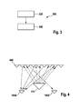
- Fig. 4 shows a representation of an object at a time during object classification according to an embodiment of the present invention. Shown are a first vehicle camera 105A, a second vehicle camera 105B, a headlight 170, and an object 480.
- the first vehicle camera 105A, the second vehicle camera 105B, and the headlight 170 may be part of a vehicle such as the vehicle Fig. 1 be.
- the first vehicle camera 105A and the second vehicle camera 105B may be part of a stereo camera or a stereo camera unit.
- the headlight 170 may thus be a vehicle headlight and, in particular, a front headlight.
- the object 480 may be, for example, a reflector on a guide post.
- the headlight 170 illuminates the object 480.
- light rays of light emitted by the headlight 170 are incident on a reflecting surface of the object 480.
- the light beams of the emitted light are shown as arrows with arrowheads facing the object 480 Fig. 4 shown.
- the reflective surface of the object 480 is in Fig. 4 shown in a cross section and has a serrated profile with tapered projections on. However, the reflective surface of the object 480 could also have a different cross-sectional profile.
- the reflective surface of the object 480 reflects the light emitted by the headlight 170. Part of the light is reflected to the first vehicle camera 105A and the second vehicle camera 105B.
- the first vehicle camera 105A and the first receive second vehicle camera 105B Due to the cross-sectional profile and the angle of incidence of the light at the reflecting surface of the object, the first vehicle camera 105A and the first receive second vehicle camera 105B a different amount of light, light intensity, brightness, etc. of the reflected light. Light rays of the reflected light are shown as arrows with arrowheads pointing to the vehicle cameras 105A and 105B in FIG Fig. 4 shown. On the basis of the received light quantities, light intensities, brightnesses, etc. of the reflected light, for example, the method Fig. 2 and optionally additionally the method Fig. 3 or further applications are advantageously carried out.
- the properties of the reflector 480 are used to classify it as reflective. Due to the structure of the reflector 480 on the baffle, a different amount of reflected light reaches the individual cameras 105A and 105B of the stereo system. This difference can now be determined and used to determine if it is the reflection of a lead post or not. In the present case in Fig. 4 can the process off Fig. 2 determine that the object class of the object, ie the reflector, is reflective. If it was not a reflection but a light source, z. B. front lights of another vehicle, so the light arriving in the two cameras 105A and 105B within a tolerance range would be equally strong and thus there is no sufficiently large, pointing to an object from the object class for reflecting objects difference.
- FIG. 12 shows a flowchart of an algorithm 500 for determining an object class of an object from which light is emitted and / or reflected to a vehicle according to an embodiment of the present invention.
- a first step 510 bright image areas or bright spots are detected in a first image.
- a further step 520 (which may be carried out parallel to the first step 510) bright image areas or bright spots are detected in a second image.
- a further step 530 associated image areas or spots in the first image and the second image are determined.
- a first brightness value or a first brightness H1 is determined in an image area or spot in the first image.
- a second brightness value or a second brightness H2 is determined in an image area or spot in the second image.
- the z based on a comparison the first brightness H1 and the second brightness H2 made a threshold decision, the z.
- the algorithm 500 may be used in conjunction with a device such as the controller Fig. 1 , or in conjunction with a method such as the method Fig. 2 , be carried out advantageously.
- the algorithm 500 may include at least one input to a method, such as the method of FIG Fig. 3 , provide.
Applications Claiming Priority (1)
| Application Number | Priority Date | Filing Date | Title |
|---|---|---|---|
| DE102011081428A DE102011081428A1 (de) | 2011-08-23 | 2011-08-23 | Verfahren zum Bestimmen einer Objektklasse eines Objekts, von dem aus Licht zu einem Fahrzeug ausgesandt und/oder reflektiert wird |
Publications (1)
| Publication Number | Publication Date |
|---|---|
| EP2562686A1 true EP2562686A1 (de) | 2013-02-27 |
Family
ID=46581736
Family Applications (1)
| Application Number | Title | Priority Date | Filing Date |
|---|---|---|---|
| EP12174547A Withdrawn EP2562686A1 (de) | 2011-08-23 | 2012-07-02 | Verfahren zum Bestimmen einer Objektklasse eines Objekts, von dem aus Licht zu einem Fahrzeug ausgesandt und/oder reflektiert wird |
Country Status (4)
| Country | Link |
|---|---|
| US (1) | US8712637B2 (zh) |
| EP (1) | EP2562686A1 (zh) |
| CN (1) | CN102955937B (zh) |
| DE (1) | DE102011081428A1 (zh) |
Cited By (1)
| Publication number | Priority date | Publication date | Assignee | Title |
|---|---|---|---|---|
| CN109996377A (zh) * | 2017-12-29 | 2019-07-09 | 杭州海康威视数字技术股份有限公司 | 一种路灯控制方法、装置及电子设备 |
Families Citing this family (26)
| Publication number | Priority date | Publication date | Assignee | Title |
|---|---|---|---|---|
| US8282222B2 (en) | 2007-10-10 | 2012-10-09 | Gerard Dirk Smits | Image projector with reflected light tracking |
| DE102011081380A1 (de) | 2011-08-23 | 2013-02-28 | Robert Bosch Gmbh | Verfahren zur Steuerung einer Lichtaussendung eines Scheinwerfers eines Fahrzeugs |
| DE102011081425A1 (de) * | 2011-08-23 | 2013-02-28 | Robert Bosch Gmbh | Verfahren und Vorrichtung zur Klassifizierung eines sich in einem Vorfeld eines Fahrzeugs befindlichen Lichtobjekts |
| DE102012221356A1 (de) * | 2012-06-20 | 2013-12-24 | Robert Bosch Gmbh | Sensor und Verfahren zur Erfassung von Licht und Verfahren und Vorrichtung zur Ermittlung einer Farbinformation |
| DE102013226760A1 (de) * | 2013-12-19 | 2015-06-25 | Robert Bosch Gmbh | Verfahren und Vorrichtung zur Erkennung von Objektreflexionen |
| WO2015149027A1 (en) | 2014-03-28 | 2015-10-01 | Gerard Dirk Smits | Smart head-mounted projection system |
| US20150286878A1 (en) * | 2014-04-08 | 2015-10-08 | Bendix Commercial Vehicle Systems Llc | Generating an Image of the Surroundings of an Articulated Vehicle |
| US9377533B2 (en) | 2014-08-11 | 2016-06-28 | Gerard Dirk Smits | Three-dimensional triangulation and time-of-flight based tracking systems and methods |
| DE102014221883A1 (de) * | 2014-10-28 | 2016-04-28 | Robert Bosch Gmbh | Verfahren und Steuergerät zum Einstellen einer Charakteristik einer Lichtaussendung zumindest eines Scheinwerfers eines Fahrzeugs |
| US10043282B2 (en) | 2015-04-13 | 2018-08-07 | Gerard Dirk Smits | Machine vision for ego-motion, segmenting, and classifying objects |
| US9753126B2 (en) | 2015-12-18 | 2017-09-05 | Gerard Dirk Smits | Real time position sensing of objects |
| US9813673B2 (en) | 2016-01-20 | 2017-11-07 | Gerard Dirk Smits | Holographic video capture and telepresence system |
| DE102016206361A1 (de) | 2016-04-15 | 2017-10-19 | Robert Bosch Gmbh | Kameraeinrichtung für den Außenbereich eines Gebäudes |
| DE102016115705B4 (de) * | 2016-08-24 | 2018-07-12 | Dr. Ing. H.C. F. Porsche Aktiengesellschaft | Verfahren für die Erfassung von Objekten in der Umgebung eines Fahrzeugs |
| JP6752667B2 (ja) * | 2016-09-27 | 2020-09-09 | キヤノン株式会社 | 画像処理装置と画像処理方法およびプログラム |
| WO2018106360A2 (en) | 2016-10-31 | 2018-06-14 | Gerard Dirk Smits | Fast scanning lidar with dynamic voxel probing |
| CN109963744B (zh) * | 2016-11-24 | 2022-07-15 | 麦克赛尔株式会社 | 照明装置 |
| US10261183B2 (en) | 2016-12-27 | 2019-04-16 | Gerard Dirk Smits | Systems and methods for machine perception |
| GB2558661B (en) | 2017-01-16 | 2019-06-12 | Jaguar Land Rover Ltd | Vehicle lighting system |
| EP3622333A4 (en) | 2017-05-10 | 2021-06-23 | Gerard Dirk Smits | SCAN MIRROR METHODS AND SYSTEMS |
| WO2019079750A1 (en) | 2017-10-19 | 2019-04-25 | Gerard Dirk Smits | METHODS AND SYSTEMS FOR NAVIGATING A VEHICLE EQUIPPED WITH A NEW MILITARY MARKER SYSTEM |
| US10379220B1 (en) | 2018-01-29 | 2019-08-13 | Gerard Dirk Smits | Hyper-resolved, high bandwidth scanned LIDAR systems |
| DE102018007831A1 (de) | 2018-10-04 | 2019-03-28 | Daimler Ag | Verfahren zur Erkennung von Lichtsignalanlagen |
| WO2021174227A1 (en) | 2020-02-27 | 2021-09-02 | Gerard Dirk Smits | High resolution scanning of remote objects with fast sweeping laser beams and signal recovery by twitchy pixel array |
| CN114454809A (zh) * | 2020-10-31 | 2022-05-10 | 华为技术有限公司 | 一种智能灯光切换方法、系统及相关设备 |
| DE102020007773A1 (de) | 2020-12-18 | 2021-03-04 | Daimler Ag | Verfahren zum Betreiben wenigstens eines Fahrzeugscheinwerfers und Fahrzeug |
Citations (3)
| Publication number | Priority date | Publication date | Assignee | Title |
|---|---|---|---|---|
| WO2006063675A1 (de) * | 2004-12-16 | 2006-06-22 | Daimlerchrysler Ag | Verfahren zum betreiben einer leuchteinrichtung und vorrichtung zum betreiben einer leuchteinrichtung |
| DE102006004770A1 (de) * | 2005-11-09 | 2007-05-10 | Daimlerchrysler Ag | Verfahren zur bildgestützten Erkennung von Fahrzeugen im Umfeld eines Sraßenfahrzeugs |
| DE102009042476A1 (de) | 2008-09-25 | 2010-04-01 | Volkswagen Ag | Bestimmung von Zuständen in der Umgebung eines Kraftfahrzeugs mittels einer Stereokamera |
Family Cites Families (20)
| Publication number | Priority date | Publication date | Assignee | Title |
|---|---|---|---|---|
| US7596242B2 (en) * | 1995-06-07 | 2009-09-29 | Automotive Technologies International, Inc. | Image processing for vehicular applications |
| US5488700A (en) * | 1993-07-30 | 1996-01-30 | Xerox Corporation | Image rendering system with local, adaptive estimation of incident diffuse energy |
| US8538636B2 (en) * | 1995-06-07 | 2013-09-17 | American Vehicular Sciences, LLC | System and method for controlling vehicle headlights |
| US7738678B2 (en) * | 1995-06-07 | 2010-06-15 | Automotive Technologies International, Inc. | Light modulation techniques for imaging objects in or around a vehicle |
| MXPA05001880A (es) * | 2002-08-21 | 2005-06-03 | Gentex Corp | Metodos de adquisicion y procesamiento de imagen para control automatico de iluminacion exterior vehicular. |
| JP3861781B2 (ja) * | 2002-09-17 | 2006-12-20 | 日産自動車株式会社 | 前方車両追跡システムおよび前方車両追跡方法 |
| JP2004198211A (ja) * | 2002-12-18 | 2004-07-15 | Aisin Seiki Co Ltd | 移動体周辺監視装置 |
| CN100420592C (zh) * | 2003-02-21 | 2008-09-24 | 金泰克斯公司 | 自动汽车外部灯光控制系统 |
| DE10327115B3 (de) * | 2003-06-13 | 2004-11-11 | Rehau Ag + Co. | Fußgängerschutzsystem für Kraftfahrzeuge |
| DE102006016073A1 (de) * | 2005-08-24 | 2007-03-22 | Dr.Ing.H.C. F. Porsche Ag | Verfahren zur Steuerung der Leuchtweite eines Kraftfahrzeuges |
| CN101044507B (zh) * | 2005-09-01 | 2010-08-18 | 松下电器产业株式会社 | 图像处理方法以及图像处理装置 |
| GB0520829D0 (en) * | 2005-10-13 | 2005-11-23 | Univ Cambridge Tech | Image processing methods and apparatus |
| EP1964412B1 (en) * | 2005-12-21 | 2019-02-20 | Telecom Italia S.p.A. | Method for determining dense disparity fields in stereo vision |
| DE102006055904A1 (de) * | 2006-11-27 | 2008-05-29 | Adc Automotive Distance Control Systems Gmbh | Erkennung und Kategorisierung von Lichtpunkten mit einer Kamera in einer Fahrzeugumgebung |
| US8332142B2 (en) * | 2006-12-26 | 2012-12-11 | Rohm Co., Ltd. | Position display apparatus |
| DE102006062061B4 (de) * | 2006-12-29 | 2010-06-10 | Fraunhofer-Gesellschaft zur Förderung der angewandten Forschung e.V. | Vorrichtung, Verfahren und Computerprogramm zum Bestimmen einer Position basierend auf einem Kamerabild von einer Kamera |
| FR2919406B1 (fr) * | 2007-07-23 | 2009-10-23 | Commissariat Energie Atomique | Procede et dispositif de reconnaissance de position ou de mouvement d'un dispositif ou d'un etre vivant. |
| DE102008048309A1 (de) * | 2008-09-22 | 2010-04-01 | Volkswagen Ag | Verfahren und Vorrichtung zum Detektieren von Fahrzeugen bei Dunkelheit |
| DE102011081398B4 (de) * | 2011-08-23 | 2018-09-13 | Robert Bosch Gmbh | Verfahren und Vorrichtung zum Unterscheiden eines selbstleuchtenden Objekts von einem reflektierenden Objekt |
| DE102011081425A1 (de) * | 2011-08-23 | 2013-02-28 | Robert Bosch Gmbh | Verfahren und Vorrichtung zur Klassifizierung eines sich in einem Vorfeld eines Fahrzeugs befindlichen Lichtobjekts |
-
2011
- 2011-08-23 DE DE102011081428A patent/DE102011081428A1/de active Pending
-
2012
- 2012-07-02 EP EP12174547A patent/EP2562686A1/de not_active Withdrawn
- 2012-08-22 CN CN201210300113.4A patent/CN102955937B/zh active Active
- 2012-08-22 US US13/591,796 patent/US8712637B2/en not_active Expired - Fee Related
Patent Citations (3)
| Publication number | Priority date | Publication date | Assignee | Title |
|---|---|---|---|---|
| WO2006063675A1 (de) * | 2004-12-16 | 2006-06-22 | Daimlerchrysler Ag | Verfahren zum betreiben einer leuchteinrichtung und vorrichtung zum betreiben einer leuchteinrichtung |
| DE102006004770A1 (de) * | 2005-11-09 | 2007-05-10 | Daimlerchrysler Ag | Verfahren zur bildgestützten Erkennung von Fahrzeugen im Umfeld eines Sraßenfahrzeugs |
| DE102009042476A1 (de) | 2008-09-25 | 2010-04-01 | Volkswagen Ag | Bestimmung von Zuständen in der Umgebung eines Kraftfahrzeugs mittels einer Stereokamera |
Cited By (2)
| Publication number | Priority date | Publication date | Assignee | Title |
|---|---|---|---|---|
| CN109996377A (zh) * | 2017-12-29 | 2019-07-09 | 杭州海康威视数字技术股份有限公司 | 一种路灯控制方法、装置及电子设备 |
| CN109996377B (zh) * | 2017-12-29 | 2021-08-13 | 杭州海康威视数字技术股份有限公司 | 一种路灯控制方法、装置及电子设备 |
Also Published As
| Publication number | Publication date |
|---|---|
| DE102011081428A1 (de) | 2013-02-28 |
| US8712637B2 (en) | 2014-04-29 |
| CN102955937A (zh) | 2013-03-06 |
| CN102955937B (zh) | 2018-06-29 |
| US20130079983A1 (en) | 2013-03-28 |
Similar Documents
| Publication | Publication Date | Title |
|---|---|---|
| EP2562686A1 (de) | Verfahren zum Bestimmen einer Objektklasse eines Objekts, von dem aus Licht zu einem Fahrzeug ausgesandt und/oder reflektiert wird | |
| DE102011077038A1 (de) | Verfahren und Vorrichtung zur Erkennung von Objekten in einem Umfeld eines Fahrzeugs | |
| EP2748032B1 (de) | Verfahren und vorrichtung zur ansteuerung eines scheinwerfers eines fahrzeugs | |
| DE102014212162A1 (de) | Frontscheinwerfersteuerungsvorrichtung | |
| DE102010029149A1 (de) | Verfahren und Steuergerät zum Plausibilisieren eines Leuchtweite-Testwerts eines Lichtkegels eines Fahrzeugscheinwerfers | |
| DE112017006833T5 (de) | Fahrzeugbeleuchtungssystem | |
| DE102011081392A1 (de) | Verfahren zur Bestimmung einer Leuchtweite zumindest eines Scheinwerfers und Verfahren zur Kalibrierung einer Lichtaussendung zumindest eines Scheinwerfers eines Fahrzeugs | |
| WO2013190055A1 (de) | Verfahren zur automatischen anpassung einer fahrzeugbeleuchtung an eine umgebung des fahrzeugs, beleuchtungsvorrichtung und fahrzeug mit beleuchtung | |
| DE102008059630A1 (de) | Verfahren zur Erkennung von Fahrzeuglichtern und Retroreflektoren mit einem Kamerasystem | |
| DE102011081398B4 (de) | Verfahren und Vorrichtung zum Unterscheiden eines selbstleuchtenden Objekts von einem reflektierenden Objekt | |
| DE102011081432A1 (de) | Verfahren und Steuergerät zum Anpassen einer Leuchtstärke zumindest eines Scheinwerfers eines Fahrzeugs | |
| EP2562044A2 (de) | Verfahren zur Steuerung einer Lichtaussendung eines Scheinwerfers eines Fahrzeugs | |
| DE10156649B4 (de) | Verfahren und Einrichtung zur automatischen Erfassung leuchtender Objekte im Straßenverkehr | |
| DE102015218500A1 (de) | Beleuchtung und kamerabasierte Detektion von Regentropfen auf einer Scheibe | |
| DE102006004770B4 (de) | Verfahren zur bildgestützten Erkennung von Fahrzeugen im Umfeld eines Sraßenfahrzeugs | |
| EP2562685B1 (de) | Verfahren und Vorrichtung zur Klassifizierung eines sich in einem Vorfeld eines Fahrzeugs befindlichen Lichtobjekts | |
| EP2131308B1 (de) | Verfahren und Vorrichtung zum Klassifizieren eines in mindestens einem Bild einer Abbildung eines Bereichs vor einem Fahrzeug detektierten Objekts | |
| DE102017204836A1 (de) | Verfahren und Vorrichtung zum Erfassen von Objekten in der Umgebung eines Fahrzeuges | |
| DE102013213649A1 (de) | Verfahren zur Bildverarbeitung in einem Kraftfahrzeug | |
| DE102016014708A1 (de) | Verfahren zur Steuerung der Frontlichtverteilung eines Fahrzeuges | |
| DE102009040006A1 (de) | Scheinwerferanordnung für Fahrzeuge und Verfahren zum Betreiben einer Scheinwerferanordnung für Fahrzeuge | |
| DE102017000878A1 (de) | Beleuchtungsvorrichtung für ein Fahrzeug und Verfahren zur Ansteuerung einer solchen Beleuchtungsvorrichtung | |
| DE102016004289A1 (de) | Verfahren und Vorrichtung zur Steuerung einer Fahrzeugbeleuchtung und Fahrzeug mit einer solchen Vorrichtung | |
| DE102016009507A1 (de) | Erkennung von Lichtsignalen | |
| DE102013002320A1 (de) | Verfahren und Vorrichtung zur Unterstützung eines Fahrzeugführers nach einer Blendung im Straßenverkehr |
Legal Events
| Date | Code | Title | Description |
|---|---|---|---|
| PUAI | Public reference made under article 153(3) epc to a published international application that has entered the european phase |
Free format text: ORIGINAL CODE: 0009012 |
|
| AK | Designated contracting states |
Kind code of ref document: A1 Designated state(s): AL AT BE BG CH CY CZ DE DK EE ES FI FR GB GR HR HU IE IS IT LI LT LU LV MC MK MT NL NO PL PT RO RS SE SI SK SM TR |
|
| AX | Request for extension of the european patent |
Extension state: BA ME |
|
| 17P | Request for examination filed |
Effective date: 20130827 |
|
| RBV | Designated contracting states (corrected) |
Designated state(s): AL AT BE BG CH CY CZ DE DK EE ES FI FR GB GR HR HU IE IS IT LI LT LU LV MC MK MT NL NO PL PT RO RS SE SI SK SM TR |
|
| 17Q | First examination report despatched |
Effective date: 20160713 |
|
| STAA | Information on the status of an ep patent application or granted ep patent |
Free format text: STATUS: THE APPLICATION IS DEEMED TO BE WITHDRAWN |
|
| 18D | Application deemed to be withdrawn |
Effective date: 20161124 |