EP2562508A1 - Heat exchanger and method for assembling heat exchanger - Google Patents
Heat exchanger and method for assembling heat exchanger Download PDFInfo
- Publication number
- EP2562508A1 EP2562508A1 EP11771872A EP11771872A EP2562508A1 EP 2562508 A1 EP2562508 A1 EP 2562508A1 EP 11771872 A EP11771872 A EP 11771872A EP 11771872 A EP11771872 A EP 11771872A EP 2562508 A1 EP2562508 A1 EP 2562508A1
- Authority
- EP
- European Patent Office
- Prior art keywords
- flat tubes
- slits
- pair
- header tanks
- heat exchanger
- Prior art date
- Legal status (The legal status is an assumption and is not a legal conclusion. Google has not performed a legal analysis and makes no representation as to the accuracy of the status listed.)
- Withdrawn
Links
- 238000000034 method Methods 0.000 title claims description 45
- 238000004891 communication Methods 0.000 claims abstract description 12
- 230000008569 process Effects 0.000 claims description 24
- 238000003780 insertion Methods 0.000 description 17
- 230000037431 insertion Effects 0.000 description 17
- 238000005219 brazing Methods 0.000 description 9
- 230000009471 action Effects 0.000 description 7
- 239000002826 coolant Substances 0.000 description 6
- 238000005192 partition Methods 0.000 description 5
- 238000012545 processing Methods 0.000 description 5
- XAGFODPZIPBFFR-UHFFFAOYSA-N aluminium Chemical compound [Al] XAGFODPZIPBFFR-UHFFFAOYSA-N 0.000 description 2
- 229910052782 aluminium Inorganic materials 0.000 description 2
- 230000008901 benefit Effects 0.000 description 2
- FFBHFFJDDLITSX-UHFFFAOYSA-N benzyl N-[2-hydroxy-4-(3-oxomorpholin-4-yl)phenyl]carbamate Chemical compound OC1=C(NC(=O)OCC2=CC=CC=C2)C=CC(=C1)N1CCOCC1=O FFBHFFJDDLITSX-UHFFFAOYSA-N 0.000 description 2
- 230000000694 effects Effects 0.000 description 2
- 239000000945 filler Substances 0.000 description 2
- 239000000463 material Substances 0.000 description 2
- 238000012986 modification Methods 0.000 description 1
- 230000004048 modification Effects 0.000 description 1
- 230000007306 turnover Effects 0.000 description 1
Images





Classifications
-
- F—MECHANICAL ENGINEERING; LIGHTING; HEATING; WEAPONS; BLASTING
- F28—HEAT EXCHANGE IN GENERAL
- F28F—DETAILS OF HEAT-EXCHANGE AND HEAT-TRANSFER APPARATUS, OF GENERAL APPLICATION
- F28F9/00—Casings; Header boxes; Auxiliary supports for elements; Auxiliary members within casings
- F28F9/02—Header boxes; End plates
- F28F9/0202—Header boxes having their inner space divided by partitions
- F28F9/0204—Header boxes having their inner space divided by partitions for elongated header box, e.g. with transversal and longitudinal partitions
- F28F9/0214—Header boxes having their inner space divided by partitions for elongated header box, e.g. with transversal and longitudinal partitions having only longitudinal partitions
- F28F9/0217—Header boxes having their inner space divided by partitions for elongated header box, e.g. with transversal and longitudinal partitions having only longitudinal partitions the partitions being separate elements attached to header boxes
-
- F—MECHANICAL ENGINEERING; LIGHTING; HEATING; WEAPONS; BLASTING
- F28—HEAT EXCHANGE IN GENERAL
- F28D—HEAT-EXCHANGE APPARATUS, NOT PROVIDED FOR IN ANOTHER SUBCLASS, IN WHICH THE HEAT-EXCHANGE MEDIA DO NOT COME INTO DIRECT CONTACT
- F28D1/00—Heat-exchange apparatus having stationary conduit assemblies for one heat-exchange medium only, the media being in contact with different sides of the conduit wall, in which the other heat-exchange medium is a large body of fluid, e.g. domestic or motor car radiators
- F28D1/02—Heat-exchange apparatus having stationary conduit assemblies for one heat-exchange medium only, the media being in contact with different sides of the conduit wall, in which the other heat-exchange medium is a large body of fluid, e.g. domestic or motor car radiators with heat-exchange conduits immersed in the body of fluid
- F28D1/04—Heat-exchange apparatus having stationary conduit assemblies for one heat-exchange medium only, the media being in contact with different sides of the conduit wall, in which the other heat-exchange medium is a large body of fluid, e.g. domestic or motor car radiators with heat-exchange conduits immersed in the body of fluid with tubular conduits
- F28D1/053—Heat-exchange apparatus having stationary conduit assemblies for one heat-exchange medium only, the media being in contact with different sides of the conduit wall, in which the other heat-exchange medium is a large body of fluid, e.g. domestic or motor car radiators with heat-exchange conduits immersed in the body of fluid with tubular conduits the conduits being straight
- F28D1/0535—Heat-exchange apparatus having stationary conduit assemblies for one heat-exchange medium only, the media being in contact with different sides of the conduit wall, in which the other heat-exchange medium is a large body of fluid, e.g. domestic or motor car radiators with heat-exchange conduits immersed in the body of fluid with tubular conduits the conduits being straight the conduits having a non-circular cross-section
- F28D1/05366—Assemblies of conduits connected to common headers, e.g. core type radiators
- F28D1/05391—Assemblies of conduits connected to common headers, e.g. core type radiators with multiple rows of conduits or with multi-channel conduits combined with a particular flow pattern, e.g. multi-row multi-stage radiators
-
- F—MECHANICAL ENGINEERING; LIGHTING; HEATING; WEAPONS; BLASTING
- F28—HEAT EXCHANGE IN GENERAL
- F28F—DETAILS OF HEAT-EXCHANGE AND HEAT-TRANSFER APPARATUS, OF GENERAL APPLICATION
- F28F9/00—Casings; Header boxes; Auxiliary supports for elements; Auxiliary members within casings
- F28F9/02—Header boxes; End plates
- F28F9/0219—Arrangements for sealing end plates into casing or header box; Header box sub-elements
- F28F9/0224—Header boxes formed by sealing end plates into covers
-
- Y—GENERAL TAGGING OF NEW TECHNOLOGICAL DEVELOPMENTS; GENERAL TAGGING OF CROSS-SECTIONAL TECHNOLOGIES SPANNING OVER SEVERAL SECTIONS OF THE IPC; TECHNICAL SUBJECTS COVERED BY FORMER USPC CROSS-REFERENCE ART COLLECTIONS [XRACs] AND DIGESTS
- Y10—TECHNICAL SUBJECTS COVERED BY FORMER USPC
- Y10T—TECHNICAL SUBJECTS COVERED BY FORMER US CLASSIFICATION
- Y10T29/00—Metal working
- Y10T29/49—Method of mechanical manufacture
- Y10T29/4935—Heat exchanger or boiler making
Definitions
- the present invention relates to a heat exchanger that includes a pair of header tanks and a plurality of flat tubes that communicate with the header tanks, and more particularly, to an assembly structure and an assembly method of header tanks and flat tubes.
- Patent Document 1 As a heat exchanger according to the related art, as disclosed in Patent Document 1, there is a heat exchanger which includes a pair of header tanks that extend in parallel, and a plurality of flat tubes that communicate with the pair of header tanks and are lined up in two parallel rows.
- the end portions of the flat tubes are inserted into slits for flat tube insertion of the header tanks.
- the clearances of the insertion portions are narrow, and thus insertion is not easy. Therefore, end processing is performed on the end portion of the flat tube to form a tapered shape by squeezing or the like in order to ensure insertability into the slits on the header tank side.
- productivity is poor and automation is difficult.
- the end portion in the tapered shape is inserted, there is no abutting portion, resulting in a problem in management of insertion dimensions.
- the squeezing process reduces the flow path area and has a considerable effect on heat exchange performance.
- the two rows of the flat tubes are inserted in the longitudinal direction thereof to be positioned between the pair of header tanks, when the flat tubes are to be mounted between the pair of header tanks in units of one row, mounting of the second row after mounting of the first row is difficult. Therefore, the two rows of the flat tubes have to be inserted concurrently.
- the concurrent insertion of the two rows requires accuracy of insertion direction and position, and has poor productivity.
- the present invention has been made taking the foregoing circumstances into consideration, and an object thereof is to easily assemble header tanks and flat tubes without performing end processing on the flat tubes.
- communication portions of a header tank which communicate with flat tubes include a first slit which is formed over a region that retreats, from a center portion side in a width direction of a facing surface of the header tank which faces the other header tank that forms a pair, in a direction opposite to a facing direction from the center portion on one end portion side in the width direction, and a second slit which is formed over a region that retreats, from the center portion side in the width direction of the facing surface, in a direction opposite to the facing direction from the center portion on the other end portion side in the width direction.
- end portions of the flat tubes are able to be inserted from the side surface side of the header tanks into the first and second slits of the header tanks, and the flat tubes abut, in the width direction thereof, on first abutting portions of end portions on the center portion side of the facing surface of the first and second slits.
- the retreating region may be a side surface of the header tank or may be a connection portion between the facing surface and the side surface of the header tank.
- the connection portion may form a rounded portion or may form an inclined portion having a chamfered shape.
- End portions on the retreating region side of the first and second slits may be provided at right angles from the end portions on the center portion side of the facing surface, and the flat tubes may abut, in the longitudinal direction thereof, on second abutting portions of end portions on the retreating region side of the first and second slits.
- a step may be provided in the end portions on the retreating region side of the first and second slits on which the flat tubes abut in the longitudinal direction thereof, third abutting portions on which the flat tubes abut in the width direction may be formed, and a height of the step may be lower than a height of the facing surface.
- end portions on the retreating region side of the first and second slits may be provided to be parallel to the end portions on the center portion side of the facing surface, and the flat tubes, in the longitudinal direction thereof, may passes through the first and second slits and abut on fourth abutting portions in the header tanks.
- the front end and rear end in a slit hole direction of the end portions on the retreating region side of the first and second slits where it is assumed that:
- the first assembly method includes: a first process of arranging flat tubes in a first row so that end portions in a width direction thereof are on an upper side; a second process of fitting first slits on one side surface side of a pair of header tanks with both end portions of the flat tubes in the first row from above; and a third process of fitting flat tubes in a second row into second slits on the other side surface side of the pair of header tanks from above.
- the second assembly method includes: a first process of arranging a pair of header tanks so that one side surface side of the pair of header tanks are on an upper side; a second process of fitting both end portions of flat tubes in a first row into first slits on the one side surface side of the pair of header tanks; a third process of turning over the pair of header tanks and the flat tubes in the first row which fit with each other; and a fourth process of fitting flat tubes in a second row into second slits on the other side surface side of the pair of header tanks from above.
- the upper ends of the pair of header tanks may be opened to the outside before fitting the flat tubes in the second row into the second slits of the pair of header tanks, and may be closed after the fitting.
- An aspect of the present invention provides the assembly structure in which since the end portions of the flat tubes are inserted into the slits from the side surface side of the header tanks, the rounded portions of the end portions in the width direction of the flat tubes serve as guides. Therefore, insertability is ensured without performing special end processing.
- the flat tubes by causing the flat tubes to have a configuration in which various abutting portions are provided, the insertion positions may be stabilized. Therefore, assembly becomes easy, and maintaining the positioning condition becomes easier.
- An aspect of the present invention provides the first and second assembly methods in which there is an advantage that the flat tubes are able to be inserted from the side surfaces of the header tanks, and thus the pair of the header tanks and the flat tubes in the two rows may be efficiently assembled.
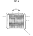
- Fig. 1 is a schematic perspective view of a heat exchanger according to an embodiment of the present invention.
- the heat exchanger of this embodiment includes a pair of header tanks 1 and 2 that extend in parallel, a plurality of flat tubes 3 (flat tubes 3A in a first row and flat tubes 3B in a second row) that communicate with the pair of header tanks 1 and 2 and are lined up in two parallel rows, and fins 4 provided between the flat tubes 3 and 3 in each of the rows.
- An arrow in the figure represents the flow direction of the air for heat exchange.
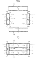
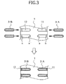
- Figs. 2 and 3 are a plan view and a side view respectively illustrating a first embodiment of an assembly structure of the header tanks 1 and 2 and the flat tubes 3.
- the header tanks 1 and 2 are cylindrical bodies (here, in this embodiment, constituted by divided bodies) made of aluminum, which have substantially rectangular cross-sections as illustrated in Fig. 2 .
- a partition wall 5 that halves the internal space thereof along the extending direction, and accordingly the internal space is partitioned into a first passage 6 and a second passage 7.
- an inlet pipe (not illustrated) of a cooling medium is connected to the first passage 6 thereof and an outlet pipe (not illustrated) of the cooling medium is connected to the second passage 7 thereof.
- a communication hole 8 is provided in the partition wall 5 thereof, and thus the first passage 6 and the second passage 7 of the header tank 2 communicate with each other. Therefore, regarding the header tank 2, the partition wall 5 itself may be omitted.
- the flat tube 3 is a tube made of aluminum, which has a flat cross-section as illustrated in Fig. 3 , both end portions in the width direction (the left and right direction of Fig. 3 ) of which are rounded portions.
- the plurality of flat tubes 3 are lined up in the extending direction of the header tanks 1 and 2 so that the flat surfaces thereof face each other. Therefore, the flat surfaces are parallel to the flow direction of the air for heat exchange which passes through the space between the header tanks 1 and 2.
- the rows of the flat tubes 3 are two rows so that the flat tubes 3A in the first row cause the first passage 6 of the header tank 1 and the first passage 6 of the header tank 2 to communicate with each other and the flat tubes 3B in the second row cause the second passage 7 of the header tank 1 and the second passage 7 of the header tank 2 to communicate with each other.
- the communication portions are joined through brazing.
- the fins 4 are, for example, corrugated fins, and are arranged by being joined between the flat surfaces of the flat tubes 3 through brazing.
- the cooling medium flows from the first passage 6 of the header tank 1 through the flat tubes 3A in the first row, flows to the first passage 6 of the header tank 2, flows from the second passage 7 of the header tank 2 which communicates with the first passage 6 of the header tank 2 through the flat tubes 3B in the second row, and flows to the second passage 7 of the header tank 1. Therefore, the flows of the cooling medium in the flat tubes 3A in the first row and the flat tubes 3B in the second row are in reverse directions and thus become a so-called counterflow.
- heat exchange is made with the air for heat exchange that passes through the space between the header tanks 1 and 2 via the corrugated fins 4.
- the communication portions on the header tank 1 side that communicate with the flat tubes 3 are a first slit 11 formed, in an angular portion (rounded portion) between a facing surface 1 a that faces the other header tank 2 that forms the pair and one side surface 1 b that continues to the facing surface 1 a, over both the surfaces 1 a and 1 b, and a second slit 12 formed, in an angular portion (rounded portion) between the facing surface 1 a and the other side surface 1 c that continues to the facing surface 1 a, over both the surfaces 1 a and 1 c.
- end portions a and a' on the facing surface 1 a side of the first and second slits 11 and 12 are rounded portions.
- End portions b and c on the side surfaces 1 b and 1 c side of the first and second slits 11 and 12 are not provided with rounded portions.
- the communication portions on the header tank 1 side that communicate with the flat tubes 3 are the first slit 11 formed over a region (the side surface 1 b, or a connection portion between the facing surface 1 a and the side surface 1 b) that retreats, from the center portion side in the width direction of the facing surface 1 a that faces the other header tank 2 that forms the pair, in a direction opposite to the facing direction from the center portion on the one end portion side in the width direction, and the second slit 12 formed over a region (the side surface 1 c, or a connection portion between the facing surface 1 a and the side surface 1 c) that retreats, from the center portion side in the width direction of the facing surface 1 a, in a direction opposite to the facing direction from the center portion on the other end portion side in the width direction.
- connection portions between the facing surface 1 a and the side surfaces 1 b and 1 c form rounded portions.
- the retreating distances of the end portions b and c on the retreating region side of the first and second slits 11 and 12 from the facing surface 1 a are greater than the plate thickness of the header tank 1 (a part of the facing surface 1 a thereof).
- the end portions b and c on the retreating region side of the first and second slits 11 and 12 are provided at right angles from the end portions a and a' on the facing surface 1 a side.
- the communication portions on the header tank 2 side that communicate with the flat tubes 3 are similar to the above communication portions.
- the end portion of the flat tube 3A in the first row is inserted into the first slit 11, and the end portion of the flat tube 3B in the second row is inserted into the second slit 12.
- the end portion of the flat tube 3A in the first row is able to be inserted from the one side surface 1 b of the header tank 1 into the first slit 11 of the header tank 1
- the end portion of the flat tube 3B in the second row is able to be inserted from the one other side surface 1c of the header tank 1 into the second slit 12 of the header tank 1.
- the end portion of the flat tube 3A in the first row abuts, in the width direction thereof, on the end portion (rounded portion) a on the facing surface 1 a side of the first slit 11, and abuts, in the longitudinal direction thereof, on the end portion b on the side surface 1 b side of the first slit 11.
- the end portion of the flat tube 3B in the second row abuts, in the width direction thereof, on the end portion (rounded portion) a' on the facing surface 1 a side of the second slit 12, and abuts, in the longitudinal direction thereof, on the end portion c on the side surface 1c side of the second slit 12.
- the end portions a and a' constitute first abutting portions and the end portions b and c constitute second abutting portions.
- the relationship between the end portions of the flat tubes 3A and 3B in the first and second rows and the first and second slits 11 and 12 of the header tank 2 is similar to that described above.
- the end portions of the flat tubes 3A in the first row are inserted into the first slits 11 of the header tanks 1 and 2 from the side (the side surface 1 b side) of the header tanks 1 and 2, the end portions (the rounded portions) in the width direction of the flat tubes 3A are caused to abut on the end portion (rounded portion) a on the facing surface 1 a side of the first slit 11, and the end portions (end surfaces) in the longitudinal direction of the flat tubes 3A are caused to abut on the end portion (right-angled portion) b on the side surface 1 b side of the first slit 11.
- the end portions of the flat tubes 3B in the second row are inserted into the second slits 12 of the header tanks 1 and 2 from the side (the side surface 1 c side) of the header tanks 1 and 2, the end portions (the rounded portions) in the width direction of the flat tubes 3B are caused to abut on the end portion (rounded portion) a' on the facing surface 1 a side of the second slit 12, and the end portions (end surfaces) in the longitudinal direction of the flat tubes 3B are caused to abut on the end portion (right-angled portion) c on the side surface 1 c side of the second slit 12.
- the end portions of the flat tubes 3A and 3B are inserted into the slits 11 and 12 from the side surface side of the header tanks 1 and 2, the rounded portions of the end portions in the width direction of the flat tubes 3A and 3B serve as guides. Therefore, insertability is ensured without performing special end processing.
- the flat tubes 3A and 3B are caused to abut in the width direction and the longitudinal direction, the insertion positions are stabilized. Therefore, assembly becomes easy. After the header tanks 1 and 2, and the flat tubes 3A and 3B are assembled as described above, the peripheries of the insertion portions are joined through brazing.
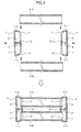
- Figs. 4 and 5 are respectively a plan view and a side view illustrating a second embodiment of the assembly structure of the header tanks 1 and 2 and the flat tubes 3.
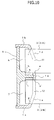
- Fig. 6 is an enlarged view of the main parts of the second embodiment of the assembly structure.
- like elements which are the same as those of the first embodiment ( Figs. 2 and 3 ) are denoted by like reference signs to simplify description, and different elements are mainly described with reference to Fig. 6 .
- the communication portions of the header tank 1 side that communicate with the flat tubes 3 are the first slit 11 formed over a region (the side surface 1 b, or a connection portion between the facing surface 1 a and the side surface 1 b) that retreats, from the center portion side in the width direction of the facing surface 1 a that faces the other header tank 2 that forms the pair, in the direction opposite to the facing direction from the center portion on the one end portion side in the width direction, and the second slit 12 formed over a region (the side surface 1 c, or a connection portion between the facing surface 1 a and the side surface 1 c) that retreats, from the center portion side in the width direction of the facing surface 1 a, in the direction opposite to the facing direction from the center portion on the other end portion side in the width direction.
- the connection portions between the facing surface 1 a and the side surfaces 1 b and 1c form rounded portions.
- a step is provided close to the outside of each of the end portions b and c on the side surfaces 1 b and 1 c side of the first and second slits 11 and 12, on which the flat tubes 3A and 3B abut in the longitudinal direction thereof, and third abutting portions d and e on which the flat tubes 3A and 3B abut in the width direction are formed.
- a height h1 (the height of the protrusion from the second abutting portions b and c) of the step (stepped wall) is less than a height h2 of the facing surface 1 a in the same direction.
- the flat tube 3A abuts, in the width direction, on the first abutting portion of the end portion a on the facing surface 1 a side of the first slit 11, abuts, in the longitudinal direction, on the second abutting portion of the end portion b on the side surface 1 b side of the first slit 11, and as the characteristics of the second embodiment, abuts on the third abutting portion d on the opposite side in the width direction.
- the flat tube 3A is caused to abut on the first abutting portion a and the third abutting portion d, in other words, is inserted therebetween, and thus the position in the width direction thereof is restricted.
- the flat tube 3A is caused to abut on the second abutting portions b and c in the longitudinal direction, and thus the insertion length thereof is restricted.
- the insertion operation includes two actions. However, insertion of the flat tube 3A from the side of the header tank 1 is enabled.
- the flat tube 3A is inserted from the side of the header tank 1 into the first slit 11 of the header tank 1, abuts on the first abutting portion a (in this state, is inserted in the longitudinal direction by h2-h1), and is thereafter press-fit in the longitudinal direction (further, by h1) of the flat tube 3A so as to cause the end portion of the flat tube 3A to abut on the second abutting portion b while being guided by the first abutting portion a and the third abutting portion d.
- both sides in the width direction may be restricted by the first abutting portions a and a' and the third abutting portions d and e though the insertion operation includes two actions. Therefore, maintaining the positioning condition becomes easier.
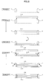
- Fig. 7 illustrates a first specific assembly method.
- Process 1 the plurality of the flat tubes 3A in the first row are arranged using tools and the like so that the end portions in the width direction are on the upper side.
- Process 2 the first slits 11 on one side of the pair of the header tanks 1 and 2 are fitted with both end portions of the flat tubes 3A in the first row from above.
- one action is performed, and in the structure of the second embodiment, two actions are performed.
- the plurality of the flat tubes 3B in the second row are fitted into the second slit 12 on the other side of the pair of the header tanks 1 and 2 from above.
- the flat tubes 3B in the second row are then fitted into the second slits 12 on the upper side of the header tanks 1 and 2, and after the fitting, the upper ends of the pair of the header tanks 1 and 2 are closed. Accordingly, assembly is completed and thereafter joining is performed through brazing.
- Fig. 8 illustrates a second specific assembly method.
- the pair of the header tanks 1 and 2 are arranged using tools and the like so that the one side surfaces thereof are on the upper side.
- both end portions of the plurality of the flat tubes 3A in the first row are fitted into the first slits 11 on the one side surfaces (side surfaces on the upper side) of the pair of the header tanks 1 and 2.
- one action is performed, and in the structure of the second embodiment, two actions are performed.
- Process 3 the pair of the header tanks 1 and 2 and the flat tubes 3A in the first row, which fit with each other, are turned over.
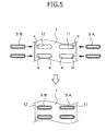
- Process 4 the plurality of the flat tubes 3B in the second row are fitted from above into the second slits 12 on the other side surfaces (side surfaces which are on the upper side after the turnover) of the pair of the header tanks 1 and 2. Even at this time, initially, the upper ends of the pair of the header tanks 1 and 2 are slightly widened to the outside, the flat tubes 3B in the second row are then fitted into the second slits 12 on the upper side of the header tanks 1 and 2, and after the fitting, the upper ends of the pair of the header tanks 1 and 2 are closed. Accordingly, assembly is completed and thereafter joining is performed through brazing.
- the flat tubes 3A and 3B are able to be inserted from the side surfaces of the header tanks 1 and 2, and thus the pair of the header tanks 1 and 2 and the flat tubes 3A and 3B in the two rows are able to be efficiently assembled.
- the flat tubes 3A in the first row and the flat tubes 3B in the second row do not need to be inserted concurrently, and thus automation of assembly becomes easy.
- Fig. 9 is a plan view illustrating a third embodiment of the assembly structure of the header tank 1 (or 2) and the flat tubes 3.
- Fig. 10 is a plan view of the assembled state of the third embodiment
- Fig. 11 is a plan view illustrating the dimensional relationship in the third embodiment
- Fig. 12 is a view taken along an arrow X of Fig. 11 .
- like elements which are the same as those of the first embodiment Figs. 2 and 3
- like reference signs to simplify description, and different elements are mainly described.
- the communication portions of the header tank 1 side that communicate with the flat tubes 3 (3A and 3B) are the first slit 11 formed over a region (a connection portion between the facing surface 1 a and the side surface 1 b) that retreats, from the center portion side in the width direction of the facing surface 1 a that faces the other header tank 2 that forms the pair, in the direction opposite to the facing direction from the center portion on the one end portion side in the width direction, and the second slit 12 formed over a region (a connection portion between the facing surface 1 a and the side surface 1 c) that retreats, from the center portion side in the width direction of the facing surface 1 a, in the direction opposite to the facing direction from the center portion on the other end portion side in the width direction.
- the connection portions between the facing surface 1 a and the side surfaces 1 b and 1 c form inclined portions 1 d and 1 e having chamfered shapes.
- end portions f and g on the retreating region (inclined portions 1d and 1 e) side of the first and second slits 11 and 12 are provided in parallel to the end portions a and a' on the center portion side of the facing surface.
- the flat tubes 3 passes through the first and second slits 11 and 12 in the longitudinal direction and are caused to abut on fourth abutting portions h and i in the header tank 1.
- the fourth abutting portions h and i are formed at the root portion of the partition wall 5.
- the flat tube 3A is inserted from the side of the header tank 1 into the first slit 11 of the header tank 1, abuts on the first abutting portion a (in this state, is inserted in the longitudinal direction by D2 described later), and is thereafter press-fit in the longitudinal direction of the flat tube 3A to be inserted into a long hole (between a and f) of the first slit 11, thereby causing the end portion of the flat tube 3A to abut on the fourth abutting portion h. Insertion of the flat tube 3B is similar to the above.
- both sides in the width direction of the flat tubes 3 (3A and 3B) are able to be restricted by the long holes of the first and second slits 11 and 12, and thus maintaining the positioning condition becomes easier.
- D2 ⁇ D1 preferably, D2>D1
- the brazing filler material may be prevented from getting into the flat tubes 3 (3A and 3B) during brazing. When the brazing filler material gets into the tubes, the flow of the cooling medium is impeded.
- assembly may be similarly performed using the first specific assembly method or the second specific assembly method described above.
Landscapes
- Engineering & Computer Science (AREA)
- Physics & Mathematics (AREA)
- Thermal Sciences (AREA)
- Mechanical Engineering (AREA)
- General Engineering & Computer Science (AREA)
- Heat-Exchange Devices With Radiators And Conduit Assemblies (AREA)
- Details Of Heat-Exchange And Heat-Transfer (AREA)
Abstract
Assembly of a header tank 1 and flat tubes 3A in a heat exchanger is simplified. A communication portion of the header tank 1 side which communicates with the flat tube 3A is a slit 11 formed over a region (a side surface 1 b, or a connection portion between a facing surface 1 a and the side surface 1 b) that retreats from a center portion side in a width direction of the facing surface 1a, from the facing surface 1 a on one end portion side in the width direction. An end portion of the flat tube 3A is able to be inserted from the side surface side of the header tank 1 into the slit 11 of the header tank 1. The flat tube 3A is caused to abut, in the width direction thereof, on a first abutting portion a of an end portion on the facing surface 1a side of the slit 11, and abut, in the longitudinal direction, on a second abutting portion b of an end portion on the side surface 1 b side of the slit 11.
Description
- The present invention relates to a heat exchanger that includes a pair of header tanks and a plurality of flat tubes that communicate with the header tanks, and more particularly, to an assembly structure and an assembly method of header tanks and flat tubes.
- As a heat exchanger according to the related art, as disclosed in
Patent Document 1, there is a heat exchanger which includes a pair of header tanks that extend in parallel, and a plurality of flat tubes that communicate with the pair of header tanks and are lined up in two parallel rows. -
- [Patent Document 1] Japanese Laid-Open Patent Publication No.
2003-075024 - However, in an assembly structure of the header tanks and the flat tubes in the heat exchanger according to the related art, the end portions of the flat tubes are inserted into slits for flat tube insertion of the header tanks. However, the clearances of the insertion portions are narrow, and thus insertion is not easy.
Therefore, end processing is performed on the end portion of the flat tube to form a tapered shape by squeezing or the like in order to ensure insertability into the slits on the header tank side. However, due to the end processing, productivity is poor and automation is difficult. In addition, when the end portion in the tapered shape is inserted, there is no abutting portion, resulting in a problem in management of insertion dimensions. In addition, the squeezing process reduces the flow path area and has a considerable effect on heat exchange performance. - In addition, in a case in which the two rows of the flat tubes are inserted in the longitudinal direction thereof to be positioned between the pair of header tanks, when the flat tubes are to be mounted between the pair of header tanks in units of one row, mounting of the second row after mounting of the first row is difficult. Therefore, the two rows of the flat tubes have to be inserted concurrently. However, the concurrent insertion of the two rows requires accuracy of insertion direction and position, and has poor productivity.
- The present invention has been made taking the foregoing circumstances into consideration, and an object thereof is to easily assemble header tanks and flat tubes without performing end processing on the flat tubes.
- In order to accomplish the object, in an assembly structure according to an embodiment of the present invention, communication portions of a header tank which communicate with flat tubes include a first slit which is formed over a region that retreats, from a center portion side in a width direction of a facing surface of the header tank which faces the other header tank that forms a pair, in a direction opposite to a facing direction from the center portion on one end portion side in the width direction, and a second slit which is formed over a region that retreats, from the center portion side in the width direction of the facing surface, in a direction opposite to the facing direction from the center portion on the other end portion side in the width direction. In addition, end portions of the flat tubes are able to be inserted from the side surface side of the header tanks into the first and second slits of the header tanks, and the flat tubes abut, in the width direction thereof, on first abutting portions of end portions on the center portion side of the facing surface of the first and second slits.
The retreating region may be a side surface of the header tank or may be a connection portion between the facing surface and the side surface of the header tank. In addition, the connection portion may form a rounded portion or may form an inclined portion having a chamfered shape. - End portions on the retreating region side of the first and second slits may be provided at right angles from the end portions on the center portion side of the facing surface, and the flat tubes may abut, in the longitudinal direction thereof, on second abutting portions of end portions on the retreating region side of the first and second slits.
Moreover, a step may be provided in the end portions on the retreating region side of the first and second slits on which the flat tubes abut in the longitudinal direction thereof, third abutting portions on which the flat tubes abut in the width direction may be formed, and a height of the step may be lower than a height of the facing surface. - Otherwise, end portions on the retreating region side of the first and second slits may be provided to be parallel to the end portions on the center portion side of the facing surface, and the flat tubes, in the longitudinal direction thereof, may passes through the first and second slits and abut on fourth abutting portions in the header tanks.
Here, regarding the front end and rear end in a slit hole direction of the end portions on the retreating region side of the first and second slits, where it is assumed that: - a plate thickness of the flat tube is D1;
- a distance in a retreating direction from the facing surface of the flat tube to the front end is D2; and
- a distance from the rear end to the end portion of the flat tube is D3,

preferably,
may be set. - As a method for assembling the heat exchanger having the structure described above, the following first and second assembly methods are proposed.
The first assembly method includes: a first process of arranging flat tubes in a first row so that end portions in a width direction thereof are on an upper side; a second process of fitting first slits on one side surface side of a pair of header tanks with both end portions of the flat tubes in the first row from above; and a third process of fitting flat tubes in a second row into second slits on the other side surface side of the pair of header tanks from above. - The second assembly method includes: a first process of arranging a pair of header tanks so that one side surface side of the pair of header tanks are on an upper side; a second process of fitting both end portions of flat tubes in a first row into first slits on the one side surface side of the pair of header tanks; a third process of turning over the pair of header tanks and the flat tubes in the first row which fit with each other; and a fourth process of fitting flat tubes in a second row into second slits on the other side surface side of the pair of header tanks from above.
- Here, in the third process of the first assembly method or in the fourth process of the second assembly method, the upper ends of the pair of header tanks may be opened to the outside before fitting the flat tubes in the second row into the second slits of the pair of header tanks, and may be closed after the fitting.
- An aspect of the present invention provides the assembly structure in which since the end portions of the flat tubes are inserted into the slits from the side surface side of the header tanks, the rounded portions of the end portions in the width direction of the flat tubes serve as guides. Therefore, insertability is ensured without performing special end processing.
In addition, by causing the flat tubes to have a configuration in which various abutting portions are provided, the insertion positions may be stabilized. Therefore, assembly becomes easy, and maintaining the positioning condition becomes easier. - An aspect of the present invention provides the first and second assembly methods in which there is an advantage that the flat tubes are able to be inserted from the side surfaces of the header tanks, and thus the pair of the header tanks and the flat tubes in the two rows may be efficiently assembled.
-
-
Fig. 1 is a schematic perspective view of a heat exchanger according to an embodiment of the present invention; -
Fig. 2 is a plan view illustrating a first embodiment of an assembly structure of header tanks and flat tubes; -
Fig. 3 is a side view of the first embodiment of the assembly structure; -
Fig. 4 is a plan view illustrating a second embodiment of the assembly structure of the header tanks and the flat tubes; -
Fig. 5 is a side view of the second embodiment of the assembly structure; -
Fig. 6 is an enlarged view of the main parts of the second embodiment of the assembly structure; -
Fig. 7 is a view illustrating a first specific assembly method; -
Fig. 8 is a view illustrating a second specific assembly method; -
Fig. 9 is a plan view illustrating a third embodiment of the assembly structure of the header tanks and the flat tubes; -
Fig. 10 is a plan view of the assembled state of the third embodiment of the assembly structure; -
Fig. 11 is a plan view illustrating the dimensional relationship in the third embodiment of the assembly structure; and -
Fig. 12 is a view taken along an arrow X ofFig. 11 . - Hereinafter, embodiments of the present invention will be described in detail.
Fig. 1 is a schematic perspective view of a heat exchanger according to an embodiment of the present invention.
The heat exchanger of this embodiment includes a pair ofheader tanks flat tubes 3A in a first row andflat tubes 3B in a second row) that communicate with the pair ofheader tanks fins 4 provided between theflat tubes -
Figs. 2 and3 are a plan view and a side view respectively illustrating a first embodiment of an assembly structure of theheader tanks flat tubes 3.
Theheader tanks Fig. 2 . In addition, in each of theheader tanks partition wall 5 that halves the internal space thereof along the extending direction, and accordingly the internal space is partitioned into afirst passage 6 and asecond passage 7. - Here, of the pair of
header tanks header tank 1, an inlet pipe (not illustrated) of a cooling medium is connected to thefirst passage 6 thereof and an outlet pipe (not illustrated) of the cooling medium is connected to thesecond passage 7 thereof.
In theother header tank 2, acommunication hole 8 is provided in thepartition wall 5 thereof, and thus thefirst passage 6 and thesecond passage 7 of theheader tank 2 communicate with each other. Therefore, regarding theheader tank 2, thepartition wall 5 itself may be omitted. - The
flat tube 3 is a tube made of aluminum, which has a flat cross-section as illustrated inFig. 3 , both end portions in the width direction (the left and right direction ofFig. 3 ) of which are rounded portions. In addition, the plurality offlat tubes 3 are lined up in the extending direction of theheader tanks header tanks - In addition, the rows of the
flat tubes 3 are two rows so that theflat tubes 3A in the first row cause thefirst passage 6 of theheader tank 1 and thefirst passage 6 of theheader tank 2 to communicate with each other and theflat tubes 3B in the second row cause thesecond passage 7 of theheader tank 1 and thesecond passage 7 of theheader tank 2 to communicate with each other. Here, the communication portions are joined through brazing.
The fins 4 (Fig. 1 ) are, for example, corrugated fins, and are arranged by being joined between the flat surfaces of theflat tubes 3 through brazing. - Here, the cooling medium flows from the
first passage 6 of theheader tank 1 through theflat tubes 3A in the first row, flows to thefirst passage 6 of theheader tank 2, flows from thesecond passage 7 of theheader tank 2 which communicates with thefirst passage 6 of theheader tank 2 through theflat tubes 3B in the second row, and flows to thesecond passage 7 of theheader tank 1. Therefore, the flows of the cooling medium in theflat tubes 3A in the first row and theflat tubes 3B in the second row are in reverse directions and thus become a so-called counterflow. In addition, when the cooling medium flows through theflat tubes header tanks corrugated fins 4. - Next, the assembly structure of the
header tanks flat tubes 3 in the heat exchanger of this embodiment will be described.
The communication portions on theheader tank 1 side that communicate with theflat tubes 3 are afirst slit 11 formed, in an angular portion (rounded portion) between a facing surface 1 a that faces theother header tank 2 that forms the pair and oneside surface 1 b that continues to the facing surface 1 a, over both thesurfaces 1 a and 1 b, and asecond slit 12 formed, in an angular portion (rounded portion) between the facing surface 1 a and the other side surface 1 c that continues to the facing surface 1 a, over both the surfaces 1 a and 1 c. In addition, end portions a and a' on the facing surface 1 a side of the first andsecond slits second slits - In other words, the communication portions on the
header tank 1 side that communicate with theflat tubes 3 are thefirst slit 11 formed over a region (theside surface 1 b, or a connection portion between the facing surface 1 a and theside surface 1 b) that retreats, from the center portion side in the width direction of the facing surface 1 a that faces theother header tank 2 that forms the pair, in a direction opposite to the facing direction from the center portion on the one end portion side in the width direction, and thesecond slit 12 formed over a region (the side surface 1 c, or a connection portion between the facing surface 1 a and the side surface 1 c) that retreats, from the center portion side in the width direction of the facing surface 1 a, in a direction opposite to the facing direction from the center portion on the other end portion side in the width direction. In this example, the connection portions between the facing surface 1 a and the side surfaces 1 b and 1 c form rounded portions. In addition, the retreating distances of the end portions b and c on the retreating region side of the first andsecond slits second slits
The communication portions on theheader tank 2 side that communicate with theflat tubes 3 are similar to the above communication portions. - The end portion of the
flat tube 3A in the first row is inserted into thefirst slit 11, and the end portion of theflat tube 3B in the second row is inserted into thesecond slit 12.
Here, the end portion of theflat tube 3A in the first row is able to be inserted from the oneside surface 1 b of theheader tank 1 into thefirst slit 11 of theheader tank 1, and the end portion of theflat tube 3B in the second row is able to be inserted from the one other side surface 1c of theheader tank 1 into thesecond slit 12 of theheader tank 1. - In addition, the end portion of the
flat tube 3A in the first row abuts, in the width direction thereof, on the end portion (rounded portion) a on the facing surface 1 a side of thefirst slit 11, and abuts, in the longitudinal direction thereof, on the end portion b on theside surface 1 b side of thefirst slit 11. In addition, the end portion of theflat tube 3B in the second row abuts, in the width direction thereof, on the end portion (rounded portion) a' on the facing surface 1 a side of thesecond slit 12, and abuts, in the longitudinal direction thereof, on the end portion c on the side surface 1c side of thesecond slit 12. Here, the end portions a and a' constitute first abutting portions and the end portions b and c constitute second abutting portions.
The relationship between the end portions of theflat tubes second slits header tank 2 is similar to that described above. - In this configuration, when the
flat tubes 3A in the first row are assembled to theheader tanks flat tubes 3A in the first row are inserted into thefirst slits 11 of theheader tanks side surface 1 b side) of theheader tanks flat tubes 3A are caused to abut on the end portion (rounded portion) a on the facing surface 1 a side of thefirst slit 11, and the end portions (end surfaces) in the longitudinal direction of theflat tubes 3A are caused to abut on the end portion (right-angled portion) b on theside surface 1 b side of thefirst slit 11. - In addition, when the
flat tubes 3B in the second row are assembled to theheader tanks flat tubes 3B in the second row are inserted into thesecond slits 12 of theheader tanks header tanks flat tubes 3B are caused to abut on the end portion (rounded portion) a' on the facing surface 1 a side of thesecond slit 12, and the end portions (end surfaces) in the longitudinal direction of theflat tubes 3B are caused to abut on the end portion (right-angled portion) c on the side surface 1 c side of thesecond slit 12. - Therefore, since the end portions of the
flat tubes slits header tanks flat tubes flat tubes
After theheader tanks flat tubes -
Figs. 4 and5 are respectively a plan view and a side view illustrating a second embodiment of the assembly structure of theheader tanks flat tubes 3.Fig. 6 is an enlarged view of the main parts of the second embodiment of the assembly structure.
In the second embodiment (Figs. 4 to 6 ), like elements which are the same as those of the first embodiment (Figs. 2 and3 ) are denoted by like reference signs to simplify description, and different elements are mainly described with reference toFig. 6 . - The communication portions of the
header tank 1 side that communicate with theflat tubes 3 are thefirst slit 11 formed over a region (theside surface 1 b, or a connection portion between the facing surface 1 a and theside surface 1 b) that retreats, from the center portion side in the width direction of the facing surface 1 a that faces theother header tank 2 that forms the pair, in the direction opposite to the facing direction from the center portion on the one end portion side in the width direction, and thesecond slit 12 formed over a region (the side surface 1 c, or a connection portion between the facing surface 1 a and the side surface 1 c) that retreats, from the center portion side in the width direction of the facing surface 1 a, in the direction opposite to the facing direction from the center portion on the other end portion side in the width direction. In this example, the connection portions between the facing surface 1 a and the side surfaces 1 b and 1c form rounded portions. - In the second embodiment, a step (stepped wall) is provided close to the outside of each of the end portions b and c on the side surfaces 1 b and 1 c side of the first and
second slits flat tubes flat tubes - Therefore, regarding the relationship between the header tank 1 (the first slit 11) and the
flat tube 3A in the second embodiment, as in the first embodiment, theflat tube 3A abuts, in the width direction, on the first abutting portion of the end portion a on the facing surface 1 a side of thefirst slit 11, abuts, in the longitudinal direction, on the second abutting portion of the end portion b on theside surface 1 b side of thefirst slit 11, and as the characteristics of the second embodiment, abuts on the third abutting portion d on the opposite side in the width direction. - Therefore, the
flat tube 3A is caused to abut on the first abutting portion a and the third abutting portion d, in other words, is inserted therebetween, and thus the position in the width direction thereof is restricted. In addition, theflat tube 3A is caused to abut on the second abutting portions b and c in the longitudinal direction, and thus the insertion length thereof is restricted.
In addition, by causing the height h1 of the step to be less than the height h2 of the facing surface 1 a, the insertion operation includes two actions. However, insertion of theflat tube 3A from the side of theheader tank 1 is enabled. - That is, the
flat tube 3A is inserted from the side of theheader tank 1 into thefirst slit 11 of theheader tank 1, abuts on the first abutting portion a (in this state, is inserted in the longitudinal direction by h2-h1), and is thereafter press-fit in the longitudinal direction (further, by h1) of theflat tube 3A so as to cause the end portion of theflat tube 3A to abut on the second abutting portion b while being guided by the first abutting portion a and the third abutting portion d. - As described above, by employing a configuration in which the third abutting portions d and e are further included, both sides in the width direction may be restricted by the first abutting portions a and a' and the third abutting portions d and e though the insertion operation includes two actions. Therefore, maintaining the positioning condition becomes easier.
- Next, a more specific method for assembling the header tanks and the flat tubes is proposed.
Fig. 7 illustrates a first specific assembly method.
InProcess 1, the plurality of theflat tubes 3A in the first row are arranged using tools and the like so that the end portions in the width direction are on the upper side.
InProcess 2, thefirst slits 11 on one side of the pair of theheader tanks flat tubes 3A in the first row from above. Here, in the structure of the first embodiment, one action is performed, and in the structure of the second embodiment, two actions are performed. - In
Process 3, the plurality of theflat tubes 3B in the second row are fitted into thesecond slit 12 on the other side of the pair of theheader tanks header tanks flat tubes 3B in the second row are then fitted into the second slits 12 on the upper side of theheader tanks header tanks -
Fig. 8 illustrates a second specific assembly method.
InProcess 1, the pair of theheader tanks
InProcess 2, both end portions of the plurality of theflat tubes 3A in the first row are fitted into thefirst slits 11 on the one side surfaces (side surfaces on the upper side) of the pair of theheader tanks - In
Process 3, the pair of theheader tanks flat tubes 3A in the first row, which fit with each other, are turned over.
InProcess 4, the plurality of theflat tubes 3B in the second row are fitted from above into the second slits 12 on the other side surfaces (side surfaces which are on the upper side after the turnover) of the pair of theheader tanks header tanks flat tubes 3B in the second row are then fitted into the second slits 12 on the upper side of theheader tanks header tanks - According to the first and second specific assembly methods, there is an advantage that the
flat tubes header tanks header tanks flat tubes flat tubes 3A in the first row and theflat tubes 3B in the second row do not need to be inserted concurrently, and thus automation of assembly becomes easy. -
Fig. 9 is a plan view illustrating a third embodiment of the assembly structure of the header tank 1 (or 2) and theflat tubes 3. In addition,Fig. 10 is a plan view of the assembled state of the third embodiment,Fig. 11 is a plan view illustrating the dimensional relationship in the third embodiment, andFig. 12 is a view taken along an arrow X ofFig. 11 .
Also in the third embodiment (Figs. 9 to 12 ), like elements which are the same as those of the first embodiment (Figs. 2 and3 ) are denoted by like reference signs to simplify description, and different elements are mainly described. - The communication portions of the
header tank 1 side that communicate with the flat tubes 3 (3A and 3B) are thefirst slit 11 formed over a region (a connection portion between the facing surface 1 a and theside surface 1 b) that retreats, from the center portion side in the width direction of the facing surface 1 a that faces theother header tank 2 that forms the pair, in the direction opposite to the facing direction from the center portion on the one end portion side in the width direction, and thesecond slit 12 formed over a region (a connection portion between the facing surface 1 a and the side surface 1 c) that retreats, from the center portion side in the width direction of the facing surface 1 a, in the direction opposite to the facing direction from the center portion on the other end portion side in the width direction. In this example, the connection portions between the facing surface 1 a and the side surfaces 1 b and 1 c form inclined portions 1 d and 1 e having chamfered shapes. - Here, end portions f and g on the retreating region (inclined portions 1d and 1 e) side of the first and
second slits
In addition, theflat tubes 3 passes through the first andsecond slits header tank 1. The fourth abutting portions h and i are formed at the root portion of thepartition wall 5. - Therefore, in this embodiment, for example, the
flat tube 3A is inserted from the side of theheader tank 1 into thefirst slit 11 of theheader tank 1, abuts on the first abutting portion a (in this state, is inserted in the longitudinal direction by D2 described later), and is thereafter press-fit in the longitudinal direction of theflat tube 3A to be inserted into a long hole (between a and f) of thefirst slit 11, thereby causing the end portion of theflat tube 3A to abut on the fourth abutting portion h. Insertion of theflat tube 3B is similar to the above. - In this configuration, although the insertion operation includes two actions, both sides in the width direction of the flat tubes 3 (3A and 3B) are able to be restricted by the long holes of the first and
second slits - Here, referring to
Figs. 11 and12 , regarding the front end and the rear end in the slit hole direction of the end portions f and g on the retreating region (inclined portions 1d and 1 e) side of the first andsecond slits - the plate thickness of the
flat tube 3 is D1; - the distance in the retreating direction from the facing surface of the flat tube to the front end is D2; and
- the distance from the rear end to the end portion of the flat tube is D3,

preferably,
are set. - By setting D2≥D1, preferably, D2>D1, regarding the first and
second slits header tank 1, when the flat tubes 3 (3A and 3B) are inserted from the side of theheader tank 1, a large insertion margin is achieved. Therefore, insertion from the side becomes easy, thereby facilitating automation. Particularly, this is effective in a case in which the plate thickness of theheader tank 1 is thin.
In addition, by setting D3>0, during brazing of the flat tubes 3 (3A and 3B) inside theheader tank 1, the brazing filler material may be prevented from getting into the flat tubes 3 (3A and 3B) during brazing. When the brazing filler material gets into the tubes, the flow of the cooling medium is impeded. - Also in the third embodiment, assembly may be similarly performed using the first specific assembly method or the second specific assembly method described above.
- The illustrated embodiments only exemplify the present invention, and of course the above-described embodiments are merely illustrative, and various improvements and modifications may be made by those skilled in the art within the scope of the claims.
-
- 1, 2
- Header tank
- 1a, 2a
- Facing surface
- 1b, 2b
- Side surface
- 1c, 2c
- Side surface
- a, a'
- First abutting portion
- b, c
- Second abutting portion
- d, e
- Third abutting portion
- h, i
- Fourth abutting portion
- 3, 3A, 3B
- Flat tube
- 4
- Corrugated fin
- 5
- Partition wall
- 6
- First passage
- 7
- Second passage
- 8
- Communication hole
- 11
- First slit
- 12
- Second slit
Claims (14)
- A heat exchanger comprising:a pair of header tanks which extend in parallel; anda plurality of flat tubes which communicate with the pair of header tanks and are lined up in two parallel rows,wherein communication portions of the header tank which communicate with the flat tubes include:a first slit which is formed over a region that retreats, from a center portion side in a width direction of a facing surface of the header tank which faces the other header tank that forms the pair, in a direction opposite to a facing direction from the center portion on one end portion side in the width direction; anda second slit which is formed over a region that retreats, from the center portion side in the width direction of the facing surface, in a direction opposite to the facing direction from the center portion on the other end portion side in the width direction,wherein end portions of the flat tubes are able to be inserted from the side surface side of the header tanks into the first and second slits of the header tanks, andwherein the flat tubes abut, in the width direction thereof, on first abutting portions of end portions on the center portion side of the facing surface of the first and second slits.
- The heat exchanger according to claim 1,
wherein the retreating region is a side surface of the header tank. - The heat exchanger according to claim 1,
wherein the retreating region is a connection portion between the facing surface and the side surface of the header tank. - The heat exchanger according to claim 3,
wherein the connection portion forms a rounded portion. - The heat exchanger according to claim 3,
wherein the connection portion forms an inclined portion having a chamfered shape. - The heat exchanger according to claim 1,
wherein end portions on the retreating region side of the first and second slits are provided at right angles from the end portions of the center portion side of the facing surface, and
wherein the flat tubes abut, in the longitudinal direction thereof, on second abutting portions of end portions on the retreating region side of the first and second slits. - The heat exchanger according to claim 6,
wherein a step is provided in the end portions on the retreating region side of the first and second slits on which the flat tubes abut in the longitudinal direction thereof, so that third abutting portions on which the flat tubes abut in the width direction are formed, and a height of the step is less than a height of the facing surface. - The heat exchanger according to claim 1,
wherein end portions on the retreating region side of the first and second slits are provided to be parallel to the end portions on the center portion side of the facing surface, and
wherein the flat tubes, in the longitudinal direction thereof, passes through the first and second slits and abut on fourth abutting portions in the header tanks. - The heat exchanger according to claim 8,
wherein, regarding front end and rear end in a slit hole direction of the end portions on the retreating region side of the first and second slits, where it is assumed that:a plate thickness of the flat tube is D1;a distance in a retreating direction from the facing surface of the flat tube to the front end is D2; anda distance from the rear end to the end portion of the flat tube is D3,D2≥D1 and D3>0are set. - The heat exchanger according to claim 9,
wherein, regarding D1 and D2, D2>D1 is set. - A method of assembling a heat exchanger, comprising:a first process of arranging flat tubes in a first row so that end portions in a width direction thereof are on an upper side;a second process of fitting first slits on one side surface side of a pair of header tanks with both end portions of the flat tubes in the first row from above; anda third process of fitting flat tubes in a second row into second slits on the other side surface side of the pair of header tanks from above.
- The method of assembling the heat exchanger according to claim 11,
wherein in the third process, the upper ends of the pair of header tanks are opened to the outside before fitting the flat tubes in the second row into the second slits of the pair of header tanks, and are closed after the fitting. - A method of assembling a heat exchanger, comprising:a first process of arranging a pair of header tanks so that one side surface side of the pair of header tanks are on an upper side;a second process of fitting both end portions of flat tubes in a first row into first slits on the one side surface side of the pair of header tanks;a third process of turning over the pair of header tanks and the flat tubes in the first row which fit with each other; anda fourth process of fitting flat tubes in a second row into second slits on the other side surface side of the pair of header tanks from above.
- The method of assembling the heat exchanger according to claim 13,
wherein, in the fourth process, the upper ends of the pair of header tanks are opened to the outside before fitting the flat tubes in the second row into the second slits of the pair of header tanks, and are closed after the fitting.
Applications Claiming Priority (3)
| Application Number | Priority Date | Filing Date | Title |
|---|---|---|---|
| JP2010095643 | 2010-04-19 | ||
| JP2010243173A JP5341863B2 (en) | 2010-04-19 | 2010-10-29 | Heat exchanger and heat exchanger assembly method |
| PCT/JP2011/058763 WO2011132536A1 (en) | 2010-04-19 | 2011-04-07 | Heat exchanger and method for assembling heat exchanger |
Publications (1)
| Publication Number | Publication Date |
|---|---|
| EP2562508A1 true EP2562508A1 (en) | 2013-02-27 |
Family
ID=44834067
Family Applications (1)
| Application Number | Title | Priority Date | Filing Date |
|---|---|---|---|
| EP11771872A Withdrawn EP2562508A1 (en) | 2010-04-19 | 2011-04-07 | Heat exchanger and method for assembling heat exchanger |
Country Status (5)
| Country | Link |
|---|---|
| US (1) | US20130032317A1 (en) |
| EP (1) | EP2562508A1 (en) |
| JP (1) | JP5341863B2 (en) |
| CN (1) | CN102869946A (en) |
| WO (1) | WO2011132536A1 (en) |
Families Citing this family (5)
| Publication number | Priority date | Publication date | Assignee | Title |
|---|---|---|---|---|
| JP6514996B2 (en) * | 2015-09-04 | 2019-05-15 | 株式会社ケーヒン・サーマル・テクノロジー | Heat exchanger |
| CN106871700A (en) * | 2015-12-10 | 2017-06-20 | 丹佛斯微通道换热器(嘉兴)有限公司 | For the header and heat exchanger of heat exchanger |
| WO2020100897A1 (en) * | 2018-11-12 | 2020-05-22 | 三菱電機株式会社 | Heat exchanger and heat exchanger manufacturing method |
| JP7513911B2 (en) * | 2022-03-31 | 2024-07-10 | ダイキン工業株式会社 | Heat exchanger manufacturing apparatus and method |
| JP7758257B1 (en) * | 2024-11-22 | 2025-10-22 | 三菱電機株式会社 | Heat exchanger and method for manufacturing the same |
Family Cites Families (13)
| Publication number | Priority date | Publication date | Assignee | Title |
|---|---|---|---|---|
| US3440704A (en) * | 1967-12-26 | 1969-04-29 | Rudy Mfg Co | Method of constructing a continuous tube finned heat exchanger |
| JP2000304486A (en) * | 1999-04-23 | 2000-11-02 | Sanden Corp | Heat exchanger and method of manufacturing the same |
| FR2793014B1 (en) * | 1999-04-28 | 2001-07-27 | Valeo Thermique Moteur Sa | HEAT EXCHANGER FOR HIGH PRESSURE FLUID |
| JP4554144B2 (en) | 2001-06-18 | 2010-09-29 | 昭和電工株式会社 | Evaporator |
| JP4300508B2 (en) * | 2002-12-25 | 2009-07-22 | 株式会社ティラド | Plate fin and heat exchanger core for heat exchanger |
| CN100541108C (en) * | 2003-08-01 | 2009-09-16 | 昭和电工株式会社 | Header box and heat exchanger having same |
| US7426958B2 (en) * | 2003-08-19 | 2008-09-23 | Visteon Global Technologies Inc. | Header for heat exchanger |
| JP4613083B2 (en) * | 2004-03-17 | 2011-01-12 | 昭和電工株式会社 | Heat exchanger |
| JP4448354B2 (en) * | 2004-03-22 | 2010-04-07 | 株式会社日本クライメイトシステムズ | Heat exchanger |
| CN1981176B (en) * | 2004-07-05 | 2010-06-16 | 昭和电工株式会社 | Heat exchanger |
| DE102006025727A1 (en) * | 2005-08-04 | 2007-02-08 | Visteon Global Technologies, Inc., Van Buren Township | Heat exchanger for vehicles and method for its production |
| KR101182185B1 (en) * | 2006-05-17 | 2012-09-12 | 한라공조주식회사 | A Structure and Assembling Method for a Heat Exchanger |
| JP2008002746A (en) * | 2006-06-22 | 2008-01-10 | Kenji Umetsu | Air heat exchanger of high performance |
-
2010
- 2010-10-29 JP JP2010243173A patent/JP5341863B2/en not_active Expired - Fee Related
-
2011
- 2011-04-07 US US13/642,402 patent/US20130032317A1/en not_active Abandoned
- 2011-04-07 WO PCT/JP2011/058763 patent/WO2011132536A1/en not_active Ceased
- 2011-04-07 CN CN2011800195659A patent/CN102869946A/en active Pending
- 2011-04-07 EP EP11771872A patent/EP2562508A1/en not_active Withdrawn
Non-Patent Citations (1)
| Title |
|---|
| See references of WO2011132536A1 * |
Also Published As
| Publication number | Publication date |
|---|---|
| JP5341863B2 (en) | 2013-11-13 |
| JP2011242114A (en) | 2011-12-01 |
| US20130032317A1 (en) | 2013-02-07 |
| CN102869946A (en) | 2013-01-09 |
| WO2011132536A1 (en) | 2011-10-27 |
Similar Documents
| Publication | Publication Date | Title |
|---|---|---|
| US9377252B2 (en) | Heat exchanger and casing for the heat exchanger | |
| KR100261006B1 (en) | Flat tube for radiator | |
| US7806170B2 (en) | Heat exchanger | |
| JP5809931B2 (en) | Heat exchanger | |
| US20130032317A1 (en) | Heat Exchanger and Method for Assembling Heat Exchanger | |
| US20100051249A1 (en) | Heat exchanger and its manufacturing method | |
| CN102483308A (en) | Heat exchanger | |
| EP2871437A1 (en) | Heat exchanger | |
| JP2008275246A (en) | Header plateless heat exchanger | |
| JPH0735491A (en) | Header tank for heat exchanger | |
| KR20120003033A (en) | heat transmitter | |
| KR101344521B1 (en) | heat transmitter | |
| JP2008224057A (en) | Heat exchanger, header tank of heat exchanger, and its manufacturing method | |
| JP2005337606A (en) | Stacked heat exchanger and its manufacturing method | |
| CN101451793B (en) | Heat exchanger and its header | |
| EP1970661A1 (en) | Heat exchanger | |
| JP2005077003A (en) | Heat exchanger | |
| CN104930905A (en) | Heat exchanger | |
| EP3252421A1 (en) | Heat exchanger assembly | |
| CN201196549Y (en) | Liquid header and the heat exchanger it is applied to | |
| KR102885577B1 (en) | Heat exchanger and method for manufacturing the same | |
| JP4787511B2 (en) | Joining structure of heat exchanger and joining method thereof | |
| KR101566546B1 (en) | Louver fin type heat exchanger | |
| JP4774753B2 (en) | Heat exchanger and manufacturing method thereof | |
| EP1744116A2 (en) | Heat exchanger |
Legal Events
| Date | Code | Title | Description |
|---|---|---|---|
| PUAI | Public reference made under article 153(3) epc to a published international application that has entered the european phase |
Free format text: ORIGINAL CODE: 0009012 |
|
| 17P | Request for examination filed |
Effective date: 20121005 |
|
| AK | Designated contracting states |
Kind code of ref document: A1 Designated state(s): AL AT BE BG CH CY CZ DE DK EE ES FI FR GB GR HR HU IE IS IT LI LT LU LV MC MK MT NL NO PL PT RO RS SE SI SK SM TR |
|
| DAX | Request for extension of the european patent (deleted) | ||
| STAA | Information on the status of an ep patent application or granted ep patent |
Free format text: STATUS: THE APPLICATION HAS BEEN WITHDRAWN |
|
| 18W | Application withdrawn |
Effective date: 20140203 |