EP2562504B1 - Clinker kiln with slider for tertiary air duct - Google Patents
Clinker kiln with slider for tertiary air duct Download PDFInfo
- Publication number
- EP2562504B1 EP2562504B1 EP12181237.4A EP12181237A EP2562504B1 EP 2562504 B1 EP2562504 B1 EP 2562504B1 EP 12181237 A EP12181237 A EP 12181237A EP 2562504 B1 EP2562504 B1 EP 2562504B1
- Authority
- EP
- European Patent Office
- Prior art keywords
- tertiary air
- shutoff
- air duct
- slider unit
- control device
- Prior art date
- Legal status (The legal status is an assumption and is not a legal conclusion. Google has not performed a legal analysis and makes no representation as to the accuracy of the status listed.)
- Not-in-force
Links
Images



Classifications
-
- F—MECHANICAL ENGINEERING; LIGHTING; HEATING; WEAPONS; BLASTING
- F27—FURNACES; KILNS; OVENS; RETORTS
- F27B—FURNACES, KILNS, OVENS OR RETORTS IN GENERAL; OPEN SINTERING OR LIKE APPARATUS
- F27B7/00—Rotary-drum furnaces, i.e. horizontal or slightly inclined
- F27B7/20—Details, accessories or equipment specially adapted for rotary-drum furnaces
- F27B7/42—Arrangement of controlling, monitoring, alarm or like devices
-
- F—MECHANICAL ENGINEERING; LIGHTING; HEATING; WEAPONS; BLASTING
- F16—ENGINEERING ELEMENTS AND UNITS; GENERAL MEASURES FOR PRODUCING AND MAINTAINING EFFECTIVE FUNCTIONING OF MACHINES OR INSTALLATIONS; THERMAL INSULATION IN GENERAL
- F16K—VALVES; TAPS; COCKS; ACTUATING-FLOATS; DEVICES FOR VENTING OR AERATING
- F16K3/00—Gate valves or sliding valves, i.e. cut-off apparatus with closing members having a sliding movement along the seat for opening and closing
- F16K3/02—Gate valves or sliding valves, i.e. cut-off apparatus with closing members having a sliding movement along the seat for opening and closing with flat sealing faces; Packings therefor
- F16K3/029—Gate valves or sliding valves, i.e. cut-off apparatus with closing members having a sliding movement along the seat for opening and closing with flat sealing faces; Packings therefor with two or more gates
-
- F—MECHANICAL ENGINEERING; LIGHTING; HEATING; WEAPONS; BLASTING
- F23—COMBUSTION APPARATUS; COMBUSTION PROCESSES
- F23L—SUPPLYING AIR OR NON-COMBUSTIBLE LIQUIDS OR GASES TO COMBUSTION APPARATUS IN GENERAL ; VALVES OR DAMPERS SPECIALLY ADAPTED FOR CONTROLLING AIR SUPPLY OR DRAUGHT IN COMBUSTION APPARATUS; INDUCING DRAUGHT IN COMBUSTION APPARATUS; TOPS FOR CHIMNEYS OR VENTILATING SHAFTS; TERMINALS FOR FLUES
- F23L13/00—Construction of valves or dampers for controlling air supply or draught
- F23L13/06—Construction of valves or dampers for controlling air supply or draught slidable only
-
- F—MECHANICAL ENGINEERING; LIGHTING; HEATING; WEAPONS; BLASTING
- F27—FURNACES; KILNS; OVENS; RETORTS
- F27B—FURNACES, KILNS, OVENS OR RETORTS IN GENERAL; OPEN SINTERING OR LIKE APPARATUS
- F27B7/00—Rotary-drum furnaces, i.e. horizontal or slightly inclined
- F27B7/20—Details, accessories or equipment specially adapted for rotary-drum furnaces
-
- F—MECHANICAL ENGINEERING; LIGHTING; HEATING; WEAPONS; BLASTING
- F27—FURNACES; KILNS; OVENS; RETORTS
- F27D—DETAILS OR ACCESSORIES OF FURNACES, KILNS, OVENS OR RETORTS, IN SO FAR AS THEY ARE OF KINDS OCCURRING IN MORE THAN ONE KIND OF FURNACE
- F27D9/00—Cooling of furnaces or of charges therein
-
- F—MECHANICAL ENGINEERING; LIGHTING; HEATING; WEAPONS; BLASTING
- F27—FURNACES; KILNS; OVENS; RETORTS
- F27D—DETAILS OR ACCESSORIES OF FURNACES, KILNS, OVENS OR RETORTS, IN SO FAR AS THEY ARE OF KINDS OCCURRING IN MORE THAN ONE KIND OF FURNACE
- F27D99/00—Subject matter not provided for in other groups of this subclass
- F27D99/0073—Seals
Definitions
- the present invention relates to a slider unit for a tertiary air duct between a clinker cooler and a calciner of a clinker kiln plant.
- Cement clinker also short referred to as clinker
- the clinker is discharged from the hot end of the rotary kiln ontb a cooling grate of a clinker cooler.
- the clinker resting on top of the cooling grate is cooled by a gas or a mixture of gases, usually air.
- the air is strongly heated, at least in the area close to the kiln. This strongly heated air has a temperature of approximately 750-1300°C and carries a high amount of dust.
- the heated air is extracted from the clinker cooler at the kiln hood and/or the cooler roof and fed via a so-called tertiary air duct to some other processing stage.
- tertiary air The air is referred to as tertiary air accordingly.
- This tertiary air is normally used for pre-processing of the raw meal and mostly fed to a calciner or an upstream combustion or gasification unit, such as a combustion chamber.
- calciner is used in this application as a synonym for a "raw meal pre-processing unit" being fed with tertiary air as heat and/or oxygen source.
- the raw materials which are necessary for the production of cement clinker are at least partly decarbonised in the calciner, using the thermal energy provided by the tertiary air directly, whereas the oxygen contained in the tertiary air is used for the combustion of fuel in the secondary firing.
- the permanent optimisation of energy efficiency in cement producing plants results in an increase of tertiary air temperature.
- the tertiary air volume per time unit decreases.
- the increasing use of secondary fuels like coal with high ash content, petrol coke etc. particularly increases the amount of dust per m 3 of tertiary air, i.e. the dust load in the tertiary air.
- the flow speed inside the tertiary air duct is increased.
- shutoff devices are used for this purpose. In the most simple case these are plate-like sliders, which are inserted into the tertiary air duct orthogonally to the flow direction, thus closing it during start-up of the clinker kiln line. Foldable flaps are as well used as shutoff devices. After start-up (“Ramp up”) the shutoff devices should be completely open.
- the present invention is based on the observation that the shutoff devices are, beyond their design, often used to control the amount of tertiary air per time unit as described in DE 10 2006 023 980 A1 , for example when the clinker kiln line is not operated at full production.
- the shutoff devices are only inserted partly into the tertiary air duct, for example to split up the supply air for the combustion in the kiln and the calciner, thus ensuring oxidizing conditions at the kiln inlet.
- shutoff devices do not close the tertiary air duct completely, they are subject to strong wear as the clinker dust contained in the tertiary air is highly abrasive. As a result, the shutoff element is abraded and thereby shortened to the extent, that it cannot reliably seal the tertiary air duct. A normal restart of the clinker kiln line after an unscheduled shutdown is not possible without exchanging the shutoff device.
- shutoff element deforms due to thermal stress which can result in jamming of the shutoff device and an adjustment of the same becomes impossible.
- US 4,275,763 discloses a double slide valve for finely divided solid catalysts in fluid catalytic cracking units.
- the temperatures of the fluid may reach up to 1.400°F, i.e. about 760°C.
- the temperature of the tertiary air stream from the clinker cooler to the calciner is typically about 1200°C.
- the valve would thus never withstand the conditions in a tertiary air duct of a cement clinker kiln line.
- the US-Patent discloses a double slide valve with two valve plates being in different horizontal planes and aligned 180° to each other. Both valve plates are used for controlling a desired flow of material. If the first plate is worn off the second one is used instead.
- US 4,612,955 discloses a valve for gaseous flow streams in fluid catalytic cracking units.
- the technical teaching is -briefly summarized -to use a valve plate with an edge wear tab having an increased mounting area to thereby facilitate mounting and anchoring the edge wear tab to the valve plate.
- the present invention is based on the task, to facilitate both a reliable shutting off of a tertiary air duct and a control of the tertiary air flow.
- the slider unit can be inserted into a tertiary air duct of a clinker kiln line, hence it is located in the tertiary air flow between a clinker cooler and a calciner of the clinker kiln line.
- the slider unit can have a duct section, which can be inserted into the tertiary air duct.
- a preferably plate-like shutoff device can be inserted into the tertiary air duct in order to shut off the tertiary air duct, in other words close it completely.
- the slider unit contains at least one control device which can be inserted into the tertiary air duct in order to reduce its cross section.
- the shutoff device is not subject to noteworthy wear, as it is only inserted into the tertiary air duct to close it completely. Hence its functioning is ensured permanently.
- the control device can be inserted continuously into the tertiary air duct in order to reduce its cross section continuously and is in this position exposed to the tertiary air flow and should be designed accordingly.
- the control device is equipped with a heat resistant cladding of refractory bricks or similar material at least on its side facing towards the tertiary air flow.
- Refractory is not only stone-like, heat resistant material with 10 to 45 per cent alumina content like fire clay but, according to the general linguistic usage, all heat resistant, in particular stone-like cladding, in particular cladding made of ceramics or ceramic elements.
- air a gas or a mixture of gases used as cooling agent for the clinker.
- air or tertiary air are consequently not limited to the typical gas composition of air.
- control device is supported by the shutoff device on its downwind side that is the side facing away from the tertiary air flow. Therefore the slider unit is particularly small.
- control device is located upwind, that is the side facing towards the tertiary air flow, of its guide. Hence the guide is covered and therefore shielded against the tertiary air flow by the control device.
- the length of the control device is significantly less than the diameter of the duct section, as it does not have to shut off the tertiary air duct.
- a length of 1/3 to 2/3 of the duct diameter is sufficient. Consequently it requires only a small amount of space next to the tertiary air duct when withdrawn completely from the tertiary air duct. In addition it takes less refractory material to protect the smaller slider, which reduces costs.
- the shutoff device has at least two parallel movable shutoff segments.
- the length of each of the two shutoff segments is particularly preferable less or equal to the length of the control device.
- the shutoff device can have at least two plates, movable in parallel to each other which can be inserted into the duct section.
- At least a first shutoff segment is movable in a guidance of at least another shutoff segment. Therefore the guidance of the first shutoff segment is not exposed to the tertiary air flow when the shutoff device is open and thus protected from damage through the tertiary air.
- At least the first shutoff segment of a multi-segment shutoff device has at least one catch for another shutoff segment of the shutoff device. Thus it is sufficient to actuate the first shutoff segment to open or close the tertiary air duct.
- the shutoff device and the control device are mounted suspended above the tertiary air duct and can be lowered into the tertiary air duct. Therefore no thrust needs to be applied to close the shutoff device or to insert the control device.
- Flexible connecting elements like chains or belts can be used instead of push rods, which further reduces the required space for the slider unit.
- the control device consists of at least one carrier, which is connected to means for adjusting the control device, for example to at least one chain hoist.
- the carrier is preferably clad with refractory material e.g. bricks, particularly preferably together with an isolating layer, for example insulating wool, located, between the carrier and the refractory bricks.
- the bricks can be bolted to the carrier, securing the isolating layer.
- Such a control device has a good price/lifetime ratio.
- control device and/or the shutoff device has at least one channel for a cooling agent. This further improves durability.
- the duct section of the tertiary air duct in which the control device and/or the shutoff device are to be inserted has preferably at least one slot through which the control device and/or the shutoff device can be inserted.
- the duct section has preferably lateral guides, in the direction of movement, in which the shutoff device and/or the control device are movable.
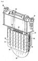
- the slider unit 1 in figure 1 has a duct section 10, which can be installed in a tertiary air duct and is clad with refractory material 12. Hence, the slider unit can be installed in a tertiary air duct as a module, which makes assembly easier.
- a box-like support structure 20 large enough to accommodate a control device 60 (shown inserted into the tertiary air duct) and a shutoff device 80 (shown partly inserted) is located on top of the duct section 10.
- the support structure 20 houses the control device 60 and the shutoff device 80 in their retracted positions.
- the support structure 20 On the upper side of the support structure 20 are drives 26, 28 for retracting the control device 60 or the shutoff device 80, respectively, out of the duct section 10 into the box like support structure 20. Thereby, the tertiary air duct can be opened completely.
- the shutoff device 80 and the control device 60 can be retracted or inserted into the duct section 10 independently (see fig. 2 ).
- In the refractory material are grooves 14, 16 as guides for the control device 60 and the shutoff device 80 (see fig. 1 ). Additionally, the shutoff device 80 is guided by the guides 18 on both sides. Simply speaking the guides 18 are rails that extend from the support structure 20 through a slot in the refractory cladding into the duct section.
- the shutoff device 80 consists of two shutoff segments are moveable parallel to each other, the example shown here is plate-shaped, further referred to as plates 82, 83.
- Plate 82 is located in front of plate 83 in a guide of the rear plate 83 (see fig. 3 ).
- the front plate 82 has a lower edge 86 or lower narrow side 86 which is adapted to the contour of the lower part of the duct section 10.
- Fastenings 84 holding the front plate 82 are attached on its upper narrow side 88.
- This upper narrow side 88 is at least approximately horizontal.
- the lateral narrow sides 92 are at least approximately parallel to each other and have a vertical longitudinal axis.
- the rear plate 83 is supported by the upper narrow side of the front plate 82.
- the rear plate 83 is equipped with steel profiles 85 on its front side used as catches 85, the free ends of which are angled downward at least approximately parallel to the front plate 82. These catches 85 bear on the upper narrow side 88 of the front plate
- the front plate 82 together with the rear plate 83 are lowered from the support structure 20 into the tertiary air duct until the rear plate 83 is located in the groove 16 and at least the lower part of the lateral narrow sides 93 bears on the groove. Consequently, the shapes of the lower part of the narrow sides 93 are adapted to the contour of the duct section 10.
- the front plate 82 slides further downwards, being guided by the steel profiles 85 attached to the rear plate 83. In its final position, the front plate also bears on the groove 16.
- the duct section 10 is now sealed for tertiary air.
- the front plate 82 can be lifted upwards via the fastenings 84. During lifting, the front plate 82 is guided by the groove 16 in the wall of the duct section 10 as well as by the lateral steel profiles 85. Approximately halfway up, the front plate 82 attaches to the rear plate 83 or the upper steel profiles 85, respectively from below and also lifts the rear plate, until both plates have reached their final position inside the support structure 20. The duct section 10 is now open (not shown). As both plates 82, 83 are guided parallel to each other in a telescope-like manner, the minimum construction height of the carrier is significantly reduced. Therefore such a shutoff device 80 can be retrofitted even in problematic locations.
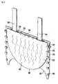
- the control device 60 has a carrier plate 62 having fastening elements 64 attached to its upper end.
- the carrier plate 62 is suspended from the fastening elements 64 (see fig. 4 ).
- Heat resistant isolating material 66 for example mineral wool felt, is attached to the front and rear sides of the carrier plate 62 as well as to the narrow sides (at least the two lateral and the lower narrow side).
- the isolating material 66 is clad with refractory bricks 70.
- the refractory bricks are bolted to the carrier plate 62 by bolts 68.
- the refractory bricks 70 have through holes 72, which have a larger diameter on the side facing away from the carrier plate 62.
- the larger sections of the through holes 72 are used to receive nuts 69, thus protecting the nuts and the projecting parts of the bolts 68 from abrasion by clinker dust.
- the holes are sealed by a curing heat resistant matter.
- the shutoff device 80 depicted in figure 5 consists of only one plate 82, which hangs from fastening elements 84 and can be lifted out color lowered into a duct section 10 by a drive 28.
- the shutoff device 80 has only one plate, which cannot cover the complete cross section of the tertiary air duct, but the plate is lowered behind the control device, so that it is sufficient to seal the remaining open part of the tertiary air duct below the control device with the single plate.
Landscapes
- Engineering & Computer Science (AREA)
- General Engineering & Computer Science (AREA)
- Mechanical Engineering (AREA)
- Chemical & Material Sciences (AREA)
- Combustion & Propulsion (AREA)
- Furnace Details (AREA)
- Environmental & Geological Engineering (AREA)
Description
- The present invention relates to a slider unit for a tertiary air duct between a clinker cooler and a calciner of a clinker kiln plant.
- Cement clinker, also short referred to as clinker, is usually produced in a rotary kiln. The clinker is discharged from the hot end of the rotary kiln ontb a cooling grate of a clinker cooler. The clinker resting on top of the cooling grate is cooled by a gas or a mixture of gases, usually air. The air is strongly heated, at least in the area close to the kiln. This strongly heated air has a temperature of approximately 750-1300°C and carries a high amount of dust. The heated air is extracted from the clinker cooler at the kiln hood and/or the cooler roof and fed via a so-called tertiary air duct to some other processing stage. The air is referred to as tertiary air accordingly. This tertiary air is normally used for pre-processing of the raw meal and mostly fed to a calciner or an upstream combustion or gasification unit, such as a combustion chamber. The term calciner is used in this application as a synonym for a "raw meal pre-processing unit" being fed with tertiary air as heat and/or oxygen source.
- The raw materials which are necessary for the production of cement clinker are at least partly decarbonised in the calciner, using the thermal energy provided by the tertiary air directly, whereas the oxygen contained in the tertiary air is used for the combustion of fuel in the secondary firing. The permanent optimisation of energy efficiency in cement producing plants results in an increase of tertiary air temperature. At the same time, the tertiary air volume per time unit decreases. The increasing use of secondary fuels like coal with high ash content, petrol coke etc. particularly increases the amount of dust per m3 of tertiary air, i.e. the dust load in the tertiary air. In order to prevent clinker dust from clogging the tertiary air duct in the long term, the flow speed inside the tertiary air duct is increased. The higher temperature and the high dust load, in combination with the higher flow speed, cause higher wear on the refractory lining inside the tertiary air duct.
- When the clinker kiln line is started up, the tertiary air duct has to be initially closed. So called shutoff devices are used for this purpose. In the most simple case these are plate-like sliders, which are inserted into the tertiary air duct orthogonally to the flow direction, thus closing it during start-up of the clinker kiln line. Foldable flaps are as well used as shutoff devices. After start-up ("Ramp up") the shutoff devices should be completely open. The present invention is based on the observation that the shutoff devices are, beyond their design, often used to control the amount of tertiary air per time unit as described in
DE 10 2006 023 980 A1 - When the shutoff devices do not close the tertiary air duct completely, they are subject to strong wear as the clinker dust contained in the tertiary air is highly abrasive. As a result, the shutoff element is abraded and thereby shortened to the extent, that it cannot reliably seal the tertiary air duct. A normal restart of the clinker kiln line after an unscheduled shutdown is not possible without exchanging the shutoff device.
- Another problem is that the shutoff element deforms due to thermal stress which can result in jamming of the shutoff device and an adjustment of the same becomes impossible.
-
US 4,275,763 discloses a double slide valve for finely divided solid catalysts in fluid catalytic cracking units. The temperatures of the fluid may reach up to 1.400°F, i.e. about 760°C. However, the temperature of the tertiary air stream from the clinker cooler to the calciner is typically about 1200°C. The valve would thus never withstand the conditions in a tertiary air duct of a cement clinker kiln line. Besides that the US-Patent discloses a double slide valve with two valve plates being in different horizontal planes and aligned 180° to each other. Both valve plates are used for controlling a desired flow of material. If the first plate is worn off the second one is used instead. -
US 4,612,955 discloses a valve for gaseous flow streams in fluid catalytic cracking units. The technical teaching is -briefly summarized -to use a valve plate with an edge wear tab having an increased mounting area to thereby facilitate mounting and anchoring the edge wear tab to the valve plate. -
US 2,494,634 teaches a damper for exposure to high temperatures. The damper has only a single slide. The technical teaching of D3 can be briefly summarized to provide a water cooled damper, in which all metal parts being exposed to hot gases are water cooled. - The present invention is based on the task, to facilitate both a reliable shutting off of a tertiary air duct and a control of the tertiary air flow.
- This task is solved by a slider unit according to
claim 1. Further improvements of the invention are specified in the dependent claims. - In particular, the slider unit can be inserted into a tertiary air duct of a clinker kiln line, hence it is located in the tertiary air flow between a clinker cooler and a calciner of the clinker kiln line. Accordingly the slider unit can have a duct section, which can be inserted into the tertiary air duct. A preferably plate-like shutoff device can be inserted into the tertiary air duct in order to shut off the tertiary air duct, in other words close it completely. In addition to the shutoff device the slider unit contains at least one control device which can be inserted into the tertiary air duct in order to reduce its cross section. The functions shutoff and control are separated in the slider unit. Therefore the shutoff device is not subject to noteworthy wear, as it is only inserted into the tertiary air duct to close it completely. Hence its functioning is ensured permanently. The control device, however, can be inserted continuously into the tertiary air duct in order to reduce its cross section continuously and is in this position exposed to the tertiary air flow and should be designed accordingly. Preferably, the control device is equipped with a heat resistant cladding of refractory bricks or similar material at least on its side facing towards the tertiary air flow. Refractory here is not only stone-like, heat resistant material with 10 to 45 per cent alumina content like fire clay but, according to the general linguistic usage, all heat resistant, in particular stone-like cladding, in particular cladding made of ceramics or ceramic elements.
- For simplification there is no differentiation in the following text between air, a gas or a mixture of gases used as cooling agent for the clinker. The terms air or tertiary air are consequently not limited to the typical gas composition of air.
- Preferably the control device is supported by the shutoff device on its downwind side that is the side facing away from the tertiary air flow. Therefore the slider unit is particularly small. Preferably, the control device is located upwind, that is the side facing towards the tertiary air flow, of its guide. Hence the guide is covered and therefore shielded against the tertiary air flow by the control device.
- Preferably, the length of the control device is significantly less than the diameter of the duct section, as it does not have to shut off the tertiary air duct. To cover the usual control range a length of 1/3 to 2/3 of the duct diameter is sufficient. Consequently it requires only a small amount of space next to the tertiary air duct when withdrawn completely from the tertiary air duct. In addition it takes less refractory material to protect the smaller slider, which reduces costs.
- Preferably the shutoff device has at least two parallel movable shutoff segments. The length of each of the two shutoff segments is particularly preferable less or equal to the length of the control device. By this method the space required for the slider unit next to the tertiary air duct can be kept particularly small. For example, the shutoff device can have at least two plates, movable in parallel to each other which can be inserted into the duct section.
- Particularly preferable, at least a first shutoff segment is movable in a guidance of at least another shutoff segment. Therefore the guidance of the first shutoff segment is not exposed to the tertiary air flow when the shutoff device is open and thus protected from damage through the tertiary air.
- Particularly preferable, at least the first shutoff segment of a multi-segment shutoff device has at least one catch for another shutoff segment of the shutoff device. Thus it is sufficient to actuate the first shutoff segment to open or close the tertiary air duct.
- Particularly preferable, the shutoff device and the control device are mounted suspended above the tertiary air duct and can be lowered into the tertiary air duct. Therefore no thrust needs to be applied to close the shutoff device or to insert the control device. Flexible connecting elements, like chains or belts can be used instead of push rods, which further reduces the required space for the slider unit.
- Preferably, the control device consists of at least one carrier, which is connected to means for adjusting the control device, for example to at least one chain hoist. The carrier is preferably clad with refractory material e.g. bricks, particularly preferably together with an isolating layer, for example insulating wool, located, between the carrier and the refractory bricks. Preferably, the bricks can be bolted to the carrier, securing the isolating layer. Such a control device has a good price/lifetime ratio.
- Preferably the control device and/or the shutoff device has at least one channel for a cooling agent. This further improves durability.
- The duct section of the tertiary air duct in which the control device and/or the shutoff device are to be inserted has preferably at least one slot through which the control device and/or the shutoff device can be inserted. The duct section has preferably lateral guides, in the direction of movement, in which the shutoff device and/or the control device are movable.
- In the following, the invention will be described by way of example, without limitation of the general inventive concept, by referring to examples of embodiment and with reference to the drawings.
-
Figure 1 shows a slider unit for a tertiary air duct, -
Figure 2 shows a partly assembled slider unit, -
Figure 3 shows a detail of a slider unit, -
Figure 4 shows a detail of a slider unit, and -
Figure 5 shows a detail of an alternative shutoff device. - The
slider unit 1 infigure 1 has aduct section 10, which can be installed in a tertiary air duct and is clad withrefractory material 12. Hence, the slider unit can be installed in a tertiary air duct as a module, which makes assembly easier. A box-like support structure 20 large enough to accommodate a control device 60 (shown inserted into the tertiary air duct) and a shutoff device 80 (shown partly inserted) is located on top of theduct section 10. Thesupport structure 20 houses thecontrol device 60 and theshutoff device 80 in their retracted positions. On the upper side of thesupport structure 20 aredrives control device 60 or theshutoff device 80, respectively, out of theduct section 10 into the box likesupport structure 20. Thereby, the tertiary air duct can be opened completely. Theshutoff device 80 and thecontrol device 60 can be retracted or inserted into theduct section 10 independently (seefig. 2 ). In the refractory material aregrooves control device 60 and the shutoff device 80 (seefig. 1 ). Additionally, theshutoff device 80 is guided by theguides 18 on both sides. Simply speaking theguides 18 are rails that extend from thesupport structure 20 through a slot in the refractory cladding into the duct section. - The
shutoff device 80 consists of two shutoff segments are moveable parallel to each other, the example shown here is plate-shaped, further referred to asplates Plate 82 is located in front ofplate 83 in a guide of the rear plate 83 (seefig. 3 ). Thefront plate 82 has alower edge 86 or lowernarrow side 86 which is adapted to the contour of the lower part of theduct section 10.Fastenings 84 holding thefront plate 82 are attached on its uppernarrow side 88. This uppernarrow side 88 is at least approximately horizontal. The lateralnarrow sides 92 are at least approximately parallel to each other and have a vertical longitudinal axis. Therear plate 83 is supported by the upper narrow side of thefront plate 82. For this purpose therear plate 83 is equipped withsteel profiles 85 on its front side used ascatches 85, the free ends of which are angled downward at least approximately parallel to thefront plate 82. These catches 85 bear on the uppernarrow side 88 of thefront plate 82. - For closing the
duct section 10, thefront plate 82 together with therear plate 83 are lowered from thesupport structure 20 into the tertiary air duct until therear plate 83 is located in thegroove 16 and at least the lower part of the lateralnarrow sides 93 bears on the groove. Consequently, the shapes of the lower part of thenarrow sides 93 are adapted to the contour of theduct section 10. When therear plate 83 bears on the inner wall of theduct section 10, thefront plate 82 slides further downwards, being guided by the steel profiles 85 attached to therear plate 83. In its final position, the front plate also bears on thegroove 16. Theduct section 10 is now sealed for tertiary air. To open the tertiary air duct thefront plate 82 can be lifted upwards via thefastenings 84. During lifting, thefront plate 82 is guided by thegroove 16 in the wall of theduct section 10 as well as by the lateral steel profiles 85. Approximately halfway up, thefront plate 82 attaches to therear plate 83 or the upper steel profiles 85, respectively from below and also lifts the rear plate, until both plates have reached their final position inside thesupport structure 20. Theduct section 10 is now open (not shown). As bothplates shutoff device 80 can be retrofitted even in problematic locations. - The
control device 60 has acarrier plate 62 havingfastening elements 64 attached to its upper end. Thecarrier plate 62 is suspended from the fastening elements 64 (seefig. 4 ). Heat resistant isolating material 66, for example mineral wool felt, is attached to the front and rear sides of thecarrier plate 62 as well as to the narrow sides (at least the two lateral and the lower narrow side). The isolating material 66 is clad withrefractory bricks 70. The refractory bricks are bolted to thecarrier plate 62 by bolts 68. Therefractory bricks 70 have throughholes 72, which have a larger diameter on the side facing away from thecarrier plate 62. The larger sections of the throughholes 72 are used to receivenuts 69, thus protecting the nuts and the projecting parts of the bolts 68 from abrasion by clinker dust. Preferably, the holes are sealed by a curing heat resistant matter. - Unlike the
shutoff device 80 shown infigures 1 to 3 , theshutoff device 80 depicted infigure 5 consists of only oneplate 82, which hangs fromfastening elements 84 and can be lifted out color lowered into aduct section 10 by adrive 28. Theshutoff device 80 has only one plate, which cannot cover the complete cross section of the tertiary air duct, but the plate is lowered behind the control device, so that it is sufficient to seal the remaining open part of the tertiary air duct below the control device with the single plate. -
- 1
- slider unit
- 10
- duct section / tertiary air duct
- 12
- heat resistant material/cladding (i.e. refractory or ceramics)
- 14
- groove
- 16
- groove
- 18
- guide
- 20
- carrier / support structure / housing
- 26
- drive
- 28
- drive
- 60
- control device
- 62
- carrier plate
- 64
- fastening element
- 66
- isolating material
- 68
- bolt
- 69
- nut
- 70
- refractory bricks / heat resistant cladding
- 72
- through hole
- 80
- shutoff device
- 82
- plate / shutoff segment
- 83
- plate / shutoff segment
- 84
- fastening element
- 85
- catch / steel profile
- 86
- lower edge / lower narrow side of the front plate
- 87
- lower edge / lower narrow side of the rear plate
- 88
- upper narrow side of the front plate
- 89
- upper narrow side of the rear plate
- 92
- lateral narrow sides of the front plate
- 93
- lateral narrow sides of the rear plate
Claims (11)
- A slider unit (1) for a tertiary air duct between a clinker cooler and a calciner of a clinker kiln line having at least one shutoff device (80) which can be inserted into the tertiary air duct (10) to shut it off and does not further reduce the cross section of the tertiary air duct (10),
characterised in that
the slider unit (1) further comprises at least one control device (60) being configured for being inserted into said duct for reducing the cross section of a section of the tertiary air duct. - The slider unit (1) of claim 1,
characterised in that
the control device (60) is arranged on the upwind facing side of the shutoff device (80). - The slider unit (1) of claim 2,
characterised in that
the control device (60) is supported by the shutoff device (80) on its downwind facing side. - The slider unit (1) of one of the preceding claims,
characterised in that
the shutoff device (80) has at least two shutoff segments (82, 83) guided in parallel to each other. - The slider unit (1) of claim 4,
characterised in that
at least a first of the shutoff segments (82) is movable in a guide of at least another of the shutoff segments (83). - The slider unit (1) of claim 4 or 5,
characterised in that
at least one of the shutoff segments (82) has at least one catch (85) for at least one other shutoff segment (83) of the shutoff device (80). - The slider unit (1) of one of the preceding claims,
characterised in that
the control device (60) has at least one carrier (62) with heat resistant cladding. - The slider unit (1) of one of the preceding claims,
characterised in that
the control device (60) has a self-supporting plate of heat resistant material. - The slider unit (1) of one of the preceding claims,
characterised in that
the control device (60) and/or the shutoff device (80) has at least one channel for a cooling agent. - The slider unit (1) of one of the preceding claims,
characterised in that
the surface of the side of the control device facing towards the tertiary air flow is smaller than the cross section of the tertiary air duct. - An installation for producing cement clinker with at least- a kiln,- a calciner,- a clinker cooler and- a tertiary air duct for conveying pre-heated air to the calcinercharacterised in that
the installation has at least one slider unit (1) of one of the preceding claims.
Applications Claiming Priority (1)
| Application Number | Priority Date | Filing Date | Title |
|---|---|---|---|
| DE102011052963.2A DE102011052963B4 (en) | 2011-08-24 | 2011-08-24 | Klinkerofenanlage with slide for Tertiärluftleitung |
Publications (2)
| Publication Number | Publication Date |
|---|---|
| EP2562504A1 EP2562504A1 (en) | 2013-02-27 |
| EP2562504B1 true EP2562504B1 (en) | 2015-03-18 |
Family
ID=46934427
Family Applications (1)
| Application Number | Title | Priority Date | Filing Date |
|---|---|---|---|
| EP12181237.4A Not-in-force EP2562504B1 (en) | 2011-08-24 | 2012-08-21 | Clinker kiln with slider for tertiary air duct |
Country Status (6)
| Country | Link |
|---|---|
| US (1) | US9121639B2 (en) |
| EP (1) | EP2562504B1 (en) |
| CN (1) | CN102954239B (en) |
| DE (1) | DE102011052963B4 (en) |
| DK (1) | DK2562504T3 (en) |
| RU (1) | RU2012136189A (en) |
Cited By (1)
| Publication number | Priority date | Publication date | Assignee | Title |
|---|---|---|---|---|
| WO2019161474A1 (en) * | 2018-02-23 | 2019-08-29 | Saint-Gobain do Brasil Produtos Industriais e para Construção Ltda. | Tertiary air valve applied to a cement production line |
Families Citing this family (6)
| Publication number | Priority date | Publication date | Assignee | Title |
|---|---|---|---|---|
| DE102012110653B3 (en) * | 2012-11-07 | 2014-05-15 | Thyssenkrupp Resource Technologies Gmbh | Cement production plant |
| CN106855132A (en) * | 2015-12-08 | 2017-06-16 | 南京凯盛国际工程有限公司 | Split blade type high temperature air-valve |
| WO2017158076A1 (en) * | 2016-03-18 | 2017-09-21 | Flsmidth A/S | Cement kiln tertiary air damper |
| EP3315888A1 (en) * | 2016-10-31 | 2018-05-02 | Holcim Technology Ltd. | Restrictor member for restricting hot, dust-laden gas flow in an air duct |
| RU181044U1 (en) * | 2017-10-30 | 2018-07-04 | Публичное акционерное общество "Транснефть" (ПАО "Транснефть") | EXTENDED VALVE SHUTTER BLOCK |
| EP4481309A1 (en) | 2023-06-19 | 2024-12-25 | Alite GmbH | Idc - indirect calciner |
Family Cites Families (14)
| Publication number | Priority date | Publication date | Assignee | Title |
|---|---|---|---|---|
| US2494634A (en) * | 1946-11-06 | 1950-01-17 | Carnegie Illinois Steel Corp | Water-cooled refractory damper |
| GB1587875A (en) * | 1976-12-21 | 1981-04-08 | Exxon Research Engineering Co | Multi-position disc slide valve |
| US4176673A (en) * | 1977-06-02 | 1979-12-04 | Mosser Industries, Inc. | Purged sliding gate valve |
| US4275763A (en) | 1979-05-25 | 1981-06-30 | Standard Oil Company (Indiana) | Double-slide valve |
| DE3343299C2 (en) * | 1983-11-30 | 1985-12-12 | Hermann Rappold & Co GmbH, 5160 Düren | Gate valve for pipelines of large nominal sizes, especially hot blast lines |
| US4612955A (en) | 1984-11-29 | 1986-09-23 | Purvis Howard A | Edge wear tab for a high temperature valve component |
| CN1042409A (en) | 1988-11-03 | 1990-05-23 | 王志章 | Vertical fluidized kilm |
| DE29924941U1 (en) * | 1998-02-12 | 2007-03-29 | Ömag-Montananlagenbau GmbH | Sintering powder raw material - with part of the material flow into the furnace separated and fed into a calciner, which is provided with tertiary air from the cooling unit after the furnace |
| AT405513B (en) | 1998-02-12 | 1999-09-27 | Oemag Montananlagenbau Gmbh | METHOD AND SYSTEM FOR BURNING POWDERED RAW MATERIAL |
| DE10202776A1 (en) * | 2002-01-25 | 2003-07-31 | Kloeckner Humboldt Wedag | Plant for the production of cement clinker |
| DE102005057346A1 (en) * | 2005-12-01 | 2007-06-06 | Khd Humboldt Wedag Gmbh | Plant for the production of cement clinker, and method of operating such a plant |
| CA2543718A1 (en) * | 2006-04-21 | 2007-10-21 | James T. Leblanc | Completely separable bolted knife gate valve body assembly with removable wear components |
| AT505027B1 (en) * | 2007-08-27 | 2008-10-15 | Holcim Technology Ltd | DEVICE FOR THROTTING HOT, DUST-LOADED GAS FLOORS |
| CN201819820U (en) | 2010-08-06 | 2011-05-04 | 天瑞集团水泥有限公司 | Continuous clinker sampling device used for cement test |
-
2011
- 2011-08-24 DE DE102011052963.2A patent/DE102011052963B4/en not_active Expired - Fee Related
-
2012
- 2012-08-07 US US13/568,731 patent/US9121639B2/en not_active Expired - Fee Related
- 2012-08-21 DK DK12181237.4T patent/DK2562504T3/en active
- 2012-08-21 EP EP12181237.4A patent/EP2562504B1/en not_active Not-in-force
- 2012-08-23 RU RU2012136189/02A patent/RU2012136189A/en unknown
- 2012-08-24 CN CN201210305520.4A patent/CN102954239B/en not_active Expired - Fee Related
Cited By (1)
| Publication number | Priority date | Publication date | Assignee | Title |
|---|---|---|---|---|
| WO2019161474A1 (en) * | 2018-02-23 | 2019-08-29 | Saint-Gobain do Brasil Produtos Industriais e para Construção Ltda. | Tertiary air valve applied to a cement production line |
Also Published As
| Publication number | Publication date |
|---|---|
| EP2562504A1 (en) | 2013-02-27 |
| CN102954239B (en) | 2016-01-06 |
| RU2012136189A (en) | 2014-02-27 |
| DE102011052963B4 (en) | 2016-05-19 |
| US20130203005A1 (en) | 2013-08-08 |
| DK2562504T3 (en) | 2015-06-15 |
| US9121639B2 (en) | 2015-09-01 |
| DE102011052963A1 (en) | 2013-02-28 |
| CN102954239A (en) | 2013-03-06 |
Similar Documents
| Publication | Publication Date | Title |
|---|---|---|
| DK2562504T3 (en) | Clinker furnace with slides for tertiary air duct | |
| RU2697555C2 (en) | Improved combustion profiles for coke production | |
| CN102144126B (en) | Multi-stage carbon conversion system with plasma melting | |
| CN111322879B (en) | Method for quickly igniting and baking furnace in Maerz kiln | |
| CS199240B2 (en) | Apparatus for firing raw materials for manufacturing cement or the like | |
| TR201904824T4 (en) | Reactor and method for gasification of a carbonaceous feedstock. | |
| US20170260089A1 (en) | Method and system for the thermal treatment of dispersible raw material | |
| UA85778C2 (en) | Installation for depuration of combustion gases, out flowing from the coke oven | |
| JPH08225347A (en) | Method of cooling high-temperature bulk material and method and apparatus for producing fired bulk material | |
| CA2227470A1 (en) | Method and apparatus for producing cement clinker | |
| US9709331B2 (en) | Plant and method for the production of cement clinker | |
| EP1774236B1 (en) | Method and cooler for cooling hot particulate material | |
| WO2017158076A1 (en) | Cement kiln tertiary air damper | |
| CN2721634Y (en) | High-efficient reciprocating slide slotted cooler | |
| US4357883A (en) | Bed drain cover assembly for a fluidized bed | |
| CN113227695B (en) | Sintering Machine | |
| RU2707370C1 (en) | Reflecting tandem furnace for aluminum scrap remelting | |
| JP4784350B2 (en) | Coke oven riser | |
| CN203256153U (en) | Gas burning lime vertical kiln roof structure | |
| CN221325062U (en) | Double-chamber kiln with hanging cylinder changed from vertical kiln | |
| Bell et al. | Coal injection—Bellefonte furnace | |
| Highton | Handling challenges with waste-derived materials | |
| DE102018116917A1 (en) | Method and device for processing lumpy, mineral material | |
| Hunt et al. | Kansanshi Copper Smelter: the first four years of operation | |
| CN101687163A (en) | Fluidized bed reactor for treating fluidizable substances and method therefor |
Legal Events
| Date | Code | Title | Description |
|---|---|---|---|
| PUAI | Public reference made under article 153(3) epc to a published international application that has entered the european phase |
Free format text: ORIGINAL CODE: 0009012 |
|
| AK | Designated contracting states |
Kind code of ref document: A1 Designated state(s): AL AT BE BG CH CY CZ DE DK EE ES FI FR GB GR HR HU IE IS IT LI LT LU LV MC MK MT NL NO PL PT RO RS SE SI SK SM TR |
|
| AX | Request for extension of the european patent |
Extension state: BA ME |
|
| 17P | Request for examination filed |
Effective date: 20130327 |
|
| GRAP | Despatch of communication of intention to grant a patent |
Free format text: ORIGINAL CODE: EPIDOSNIGR1 |
|
| RIC1 | Information provided on ipc code assigned before grant |
Ipc: F23L 13/06 20060101ALI20140606BHEP Ipc: F27D 17/00 20060101ALI20140606BHEP Ipc: F27D 99/00 20100101ALI20140606BHEP Ipc: F27B 7/42 20060101ALI20140606BHEP Ipc: F27D 9/00 20060101ALI20140606BHEP Ipc: F27B 7/20 20060101AFI20140606BHEP Ipc: F16K 3/06 20060101ALI20140606BHEP Ipc: F16K 3/02 20060101ALI20140606BHEP |
|
| INTG | Intention to grant announced |
Effective date: 20140702 |
|
| RIN1 | Information on inventor provided before grant (corrected) |
Inventor name: MATHAI, ROBERT Inventor name: HAMMERICH, JOERG |
|
| RIN1 | Information on inventor provided before grant (corrected) |
Inventor name: HAMMERICH, JOERG Inventor name: MATHAI, ROBERT |
|
| GRAP | Despatch of communication of intention to grant a patent |
Free format text: ORIGINAL CODE: EPIDOSNIGR1 |
|
| GRAS | Grant fee paid |
Free format text: ORIGINAL CODE: EPIDOSNIGR3 |
|
| INTG | Intention to grant announced |
Effective date: 20150113 |
|
| GRAA | (expected) grant |
Free format text: ORIGINAL CODE: 0009210 |
|
| AK | Designated contracting states |
Kind code of ref document: B1 Designated state(s): AL AT BE BG CH CY CZ DE DK EE ES FI FR GB GR HR HU IE IS IT LI LT LU LV MC MK MT NL NO PL PT RO RS SE SI SK SM TR |
|
| REG | Reference to a national code |
Ref country code: GB Ref legal event code: FG4D |
|
| REG | Reference to a national code |
Ref country code: CH Ref legal event code: EP |
|
| REG | Reference to a national code |
Ref country code: IE Ref legal event code: FG4D |
|
| REG | Reference to a national code |
Ref country code: AT Ref legal event code: REF Ref document number: 716832 Country of ref document: AT Kind code of ref document: T Effective date: 20150415 |
|
| REG | Reference to a national code |
Ref country code: DE Ref legal event code: R096 Ref document number: 602012005938 Country of ref document: DE Effective date: 20150430 |
|
| REG | Reference to a national code |
Ref country code: DK Ref legal event code: T3 Effective date: 20150612 |
|
| REG | Reference to a national code |
Ref country code: NO Ref legal event code: T2 Effective date: 20150318 |
|
| REG | Reference to a national code |
Ref country code: NL Ref legal event code: VDEP Effective date: 20150318 |
|
| REG | Reference to a national code |
Ref country code: NL Ref legal event code: VDEP Effective date: 20150318 |
|
| PG25 | Lapsed in a contracting state [announced via postgrant information from national office to epo] |
Ref country code: FI Free format text: LAPSE BECAUSE OF FAILURE TO SUBMIT A TRANSLATION OF THE DESCRIPTION OR TO PAY THE FEE WITHIN THE PRESCRIBED TIME-LIMIT Effective date: 20150318 Ref country code: SE Free format text: LAPSE BECAUSE OF FAILURE TO SUBMIT A TRANSLATION OF THE DESCRIPTION OR TO PAY THE FEE WITHIN THE PRESCRIBED TIME-LIMIT Effective date: 20150318 Ref country code: LT Free format text: LAPSE BECAUSE OF FAILURE TO SUBMIT A TRANSLATION OF THE DESCRIPTION OR TO PAY THE FEE WITHIN THE PRESCRIBED TIME-LIMIT Effective date: 20150318 Ref country code: HR Free format text: LAPSE BECAUSE OF FAILURE TO SUBMIT A TRANSLATION OF THE DESCRIPTION OR TO PAY THE FEE WITHIN THE PRESCRIBED TIME-LIMIT Effective date: 20150318 |
|
| REG | Reference to a national code |
Ref country code: LT Ref legal event code: MG4D |
|
| PG25 | Lapsed in a contracting state [announced via postgrant information from national office to epo] |
Ref country code: GR Free format text: LAPSE BECAUSE OF FAILURE TO SUBMIT A TRANSLATION OF THE DESCRIPTION OR TO PAY THE FEE WITHIN THE PRESCRIBED TIME-LIMIT Effective date: 20150619 Ref country code: RS Free format text: LAPSE BECAUSE OF FAILURE TO SUBMIT A TRANSLATION OF THE DESCRIPTION OR TO PAY THE FEE WITHIN THE PRESCRIBED TIME-LIMIT Effective date: 20150318 Ref country code: LV Free format text: LAPSE BECAUSE OF FAILURE TO SUBMIT A TRANSLATION OF THE DESCRIPTION OR TO PAY THE FEE WITHIN THE PRESCRIBED TIME-LIMIT Effective date: 20150318 |
|
| PG25 | Lapsed in a contracting state [announced via postgrant information from national office to epo] |
Ref country code: NL Free format text: LAPSE BECAUSE OF FAILURE TO SUBMIT A TRANSLATION OF THE DESCRIPTION OR TO PAY THE FEE WITHIN THE PRESCRIBED TIME-LIMIT Effective date: 20150318 |
|
| RAP2 | Party data changed (patent owner data changed or rights of a patent transferred) |
Owner name: ALITE GMBH |
|
| PG25 | Lapsed in a contracting state [announced via postgrant information from national office to epo] |
Ref country code: CZ Free format text: LAPSE BECAUSE OF FAILURE TO SUBMIT A TRANSLATION OF THE DESCRIPTION OR TO PAY THE FEE WITHIN THE PRESCRIBED TIME-LIMIT Effective date: 20150318 Ref country code: PT Free format text: LAPSE BECAUSE OF FAILURE TO SUBMIT A TRANSLATION OF THE DESCRIPTION OR TO PAY THE FEE WITHIN THE PRESCRIBED TIME-LIMIT Effective date: 20150720 Ref country code: EE Free format text: LAPSE BECAUSE OF FAILURE TO SUBMIT A TRANSLATION OF THE DESCRIPTION OR TO PAY THE FEE WITHIN THE PRESCRIBED TIME-LIMIT Effective date: 20150318 Ref country code: SK Free format text: LAPSE BECAUSE OF FAILURE TO SUBMIT A TRANSLATION OF THE DESCRIPTION OR TO PAY THE FEE WITHIN THE PRESCRIBED TIME-LIMIT Effective date: 20150318 Ref country code: ES Free format text: LAPSE BECAUSE OF FAILURE TO SUBMIT A TRANSLATION OF THE DESCRIPTION OR TO PAY THE FEE WITHIN THE PRESCRIBED TIME-LIMIT Effective date: 20150318 Ref country code: RO Free format text: LAPSE BECAUSE OF FAILURE TO SUBMIT A TRANSLATION OF THE DESCRIPTION OR TO PAY THE FEE WITHIN THE PRESCRIBED TIME-LIMIT Effective date: 20150318 |
|
| PG25 | Lapsed in a contracting state [announced via postgrant information from national office to epo] |
Ref country code: IS Free format text: LAPSE BECAUSE OF FAILURE TO SUBMIT A TRANSLATION OF THE DESCRIPTION OR TO PAY THE FEE WITHIN THE PRESCRIBED TIME-LIMIT Effective date: 20150718 Ref country code: PL Free format text: LAPSE BECAUSE OF FAILURE TO SUBMIT A TRANSLATION OF THE DESCRIPTION OR TO PAY THE FEE WITHIN THE PRESCRIBED TIME-LIMIT Effective date: 20150318 |
|
| REG | Reference to a national code |
Ref country code: DE Ref legal event code: R097 Ref document number: 602012005938 Country of ref document: DE |
|
| PLBE | No opposition filed within time limit |
Free format text: ORIGINAL CODE: 0009261 |
|
| STAA | Information on the status of an ep patent application or granted ep patent |
Free format text: STATUS: NO OPPOSITION FILED WITHIN TIME LIMIT |
|
| 26N | No opposition filed |
Effective date: 20151221 |
|
| PG25 | Lapsed in a contracting state [announced via postgrant information from national office to epo] |
Ref country code: SI Free format text: LAPSE BECAUSE OF FAILURE TO SUBMIT A TRANSLATION OF THE DESCRIPTION OR TO PAY THE FEE WITHIN THE PRESCRIBED TIME-LIMIT Effective date: 20150318 |
|
| PG25 | Lapsed in a contracting state [announced via postgrant information from national office to epo] |
Ref country code: MC Free format text: LAPSE BECAUSE OF FAILURE TO SUBMIT A TRANSLATION OF THE DESCRIPTION OR TO PAY THE FEE WITHIN THE PRESCRIBED TIME-LIMIT Effective date: 20150318 Ref country code: LU Free format text: LAPSE BECAUSE OF FAILURE TO SUBMIT A TRANSLATION OF THE DESCRIPTION OR TO PAY THE FEE WITHIN THE PRESCRIBED TIME-LIMIT Effective date: 20150821 |
|
| REG | Reference to a national code |
Ref country code: CH Ref legal event code: PL |
|
| REG | Reference to a national code |
Ref country code: DE Ref legal event code: R082 Ref document number: 602012005938 Country of ref document: DE Representative=s name: LOHR, JOESTINGMEIER & PARTNER, DE Ref country code: DE Ref legal event code: R081 Ref document number: 602012005938 Country of ref document: DE Owner name: IKN GMBH INGENIEURBUERO-KUEHLERBAU-NEUSTADT, DE Free format text: FORMER OWNER: IKN GMBH, 31535 NEUSTADT, DE |
|
| PG25 | Lapsed in a contracting state [announced via postgrant information from national office to epo] |
Ref country code: LI Free format text: LAPSE BECAUSE OF NON-PAYMENT OF DUE FEES Effective date: 20150831 Ref country code: CH Free format text: LAPSE BECAUSE OF NON-PAYMENT OF DUE FEES Effective date: 20150831 |
|
| REG | Reference to a national code |
Ref country code: IE Ref legal event code: MM4A |
|
| REG | Reference to a national code |
Ref country code: FR Ref legal event code: ST Effective date: 20160429 |
|
| PG25 | Lapsed in a contracting state [announced via postgrant information from national office to epo] |
Ref country code: IE Free format text: LAPSE BECAUSE OF NON-PAYMENT OF DUE FEES Effective date: 20150821 |
|
| PG25 | Lapsed in a contracting state [announced via postgrant information from national office to epo] |
Ref country code: BE Free format text: LAPSE BECAUSE OF FAILURE TO SUBMIT A TRANSLATION OF THE DESCRIPTION OR TO PAY THE FEE WITHIN THE PRESCRIBED TIME-LIMIT Effective date: 20150318 Ref country code: FR Free format text: LAPSE BECAUSE OF NON-PAYMENT OF DUE FEES Effective date: 20150831 |
|
| PG25 | Lapsed in a contracting state [announced via postgrant information from national office to epo] |
Ref country code: MT Free format text: LAPSE BECAUSE OF FAILURE TO SUBMIT A TRANSLATION OF THE DESCRIPTION OR TO PAY THE FEE WITHIN THE PRESCRIBED TIME-LIMIT Effective date: 20150318 |
|
| GBPC | Gb: european patent ceased through non-payment of renewal fee |
Effective date: 20160821 |
|
| REG | Reference to a national code |
Ref country code: AT Ref legal event code: UEP Ref document number: 716832 Country of ref document: AT Kind code of ref document: T Effective date: 20150318 |
|
| PG25 | Lapsed in a contracting state [announced via postgrant information from national office to epo] |
Ref country code: BG Free format text: LAPSE BECAUSE OF FAILURE TO SUBMIT A TRANSLATION OF THE DESCRIPTION OR TO PAY THE FEE WITHIN THE PRESCRIBED TIME-LIMIT Effective date: 20150318 Ref country code: HU Free format text: LAPSE BECAUSE OF FAILURE TO SUBMIT A TRANSLATION OF THE DESCRIPTION OR TO PAY THE FEE WITHIN THE PRESCRIBED TIME-LIMIT; INVALID AB INITIO Effective date: 20120821 Ref country code: SM Free format text: LAPSE BECAUSE OF FAILURE TO SUBMIT A TRANSLATION OF THE DESCRIPTION OR TO PAY THE FEE WITHIN THE PRESCRIBED TIME-LIMIT Effective date: 20150318 |
|
| PG25 | Lapsed in a contracting state [announced via postgrant information from national office to epo] |
Ref country code: CY Free format text: LAPSE BECAUSE OF FAILURE TO SUBMIT A TRANSLATION OF THE DESCRIPTION OR TO PAY THE FEE WITHIN THE PRESCRIBED TIME-LIMIT Effective date: 20150318 |
|
| PG25 | Lapsed in a contracting state [announced via postgrant information from national office to epo] |
Ref country code: GB Free format text: LAPSE BECAUSE OF NON-PAYMENT OF DUE FEES Effective date: 20160821 |
|
| PG25 | Lapsed in a contracting state [announced via postgrant information from national office to epo] |
Ref country code: TR Free format text: LAPSE BECAUSE OF FAILURE TO SUBMIT A TRANSLATION OF THE DESCRIPTION OR TO PAY THE FEE WITHIN THE PRESCRIBED TIME-LIMIT Effective date: 20150318 |
|
| PGFP | Annual fee paid to national office [announced via postgrant information from national office to epo] |
Ref country code: NO Payment date: 20170822 Year of fee payment: 6 Ref country code: IT Payment date: 20170824 Year of fee payment: 6 Ref country code: DE Payment date: 20170823 Year of fee payment: 6 |
|
| PGFP | Annual fee paid to national office [announced via postgrant information from national office to epo] |
Ref country code: DK Payment date: 20170824 Year of fee payment: 6 Ref country code: AT Payment date: 20170821 Year of fee payment: 6 |
|
| PG25 | Lapsed in a contracting state [announced via postgrant information from national office to epo] |
Ref country code: MK Free format text: LAPSE BECAUSE OF FAILURE TO SUBMIT A TRANSLATION OF THE DESCRIPTION OR TO PAY THE FEE WITHIN THE PRESCRIBED TIME-LIMIT Effective date: 20150318 |
|
| PG25 | Lapsed in a contracting state [announced via postgrant information from national office to epo] |
Ref country code: AL Free format text: LAPSE BECAUSE OF FAILURE TO SUBMIT A TRANSLATION OF THE DESCRIPTION OR TO PAY THE FEE WITHIN THE PRESCRIBED TIME-LIMIT Effective date: 20150318 |
|
| REG | Reference to a national code |
Ref country code: DE Ref legal event code: R119 Ref document number: 602012005938 Country of ref document: DE |
|
| REG | Reference to a national code |
Ref country code: DK Ref legal event code: EBP Effective date: 20180831 Ref country code: NO Ref legal event code: MMEP |
|
| REG | Reference to a national code |
Ref country code: AT Ref legal event code: MM01 Ref document number: 716832 Country of ref document: AT Kind code of ref document: T Effective date: 20180821 |
|
| PG25 | Lapsed in a contracting state [announced via postgrant information from national office to epo] |
Ref country code: NO Free format text: LAPSE BECAUSE OF NON-PAYMENT OF DUE FEES Effective date: 20180831 Ref country code: AT Free format text: LAPSE BECAUSE OF NON-PAYMENT OF DUE FEES Effective date: 20180821 |
|
| PG25 | Lapsed in a contracting state [announced via postgrant information from national office to epo] |
Ref country code: DE Free format text: LAPSE BECAUSE OF NON-PAYMENT OF DUE FEES Effective date: 20190301 Ref country code: DK Free format text: LAPSE BECAUSE OF NON-PAYMENT OF DUE FEES Effective date: 20180831 Ref country code: IT Free format text: LAPSE BECAUSE OF NON-PAYMENT OF DUE FEES Effective date: 20180821 |