US4176673A - Purged sliding gate valve - Google Patents
Purged sliding gate valve Download PDFInfo
- Publication number
- US4176673A US4176673A US05/862,133 US86213377A US4176673A US 4176673 A US4176673 A US 4176673A US 86213377 A US86213377 A US 86213377A US 4176673 A US4176673 A US 4176673A
- Authority
- US
- United States
- Prior art keywords
- valve
- gate
- gate member
- housing
- channel
- Prior art date
- Legal status (The legal status is an assumption and is not a legal conclusion. Google has not performed a legal analysis and makes no representation as to the accuracy of the status listed.)
- Expired - Lifetime
Links
Images


Classifications
-
- F—MECHANICAL ENGINEERING; LIGHTING; HEATING; WEAPONS; BLASTING
- F16—ENGINEERING ELEMENTS AND UNITS; GENERAL MEASURES FOR PRODUCING AND MAINTAINING EFFECTIVE FUNCTIONING OF MACHINES OR INSTALLATIONS; THERMAL INSULATION IN GENERAL
- F16J—PISTONS; CYLINDERS; SEALINGS
- F16J15/00—Sealings
- F16J15/16—Sealings between relatively-moving surfaces
- F16J15/32—Sealings between relatively-moving surfaces with elastic sealings, e.g. O-rings
- F16J15/3284—Sealings between relatively-moving surfaces with elastic sealings, e.g. O-rings characterised by their structure; Selection of materials
-
- F—MECHANICAL ENGINEERING; LIGHTING; HEATING; WEAPONS; BLASTING
- F16—ENGINEERING ELEMENTS AND UNITS; GENERAL MEASURES FOR PRODUCING AND MAINTAINING EFFECTIVE FUNCTIONING OF MACHINES OR INSTALLATIONS; THERMAL INSULATION IN GENERAL
- F16K—VALVES; TAPS; COCKS; ACTUATING-FLOATS; DEVICES FOR VENTING OR AERATING
- F16K3/00—Gate valves or sliding valves, i.e. cut-off apparatus with closing members having a sliding movement along the seat for opening and closing
- F16K3/02—Gate valves or sliding valves, i.e. cut-off apparatus with closing members having a sliding movement along the seat for opening and closing with flat sealing faces; Packings therefor
- F16K3/0281—Guillotine or blade-type valves, e.g. no passage through the valve member
-
- F—MECHANICAL ENGINEERING; LIGHTING; HEATING; WEAPONS; BLASTING
- F23—COMBUSTION APPARATUS; COMBUSTION PROCESSES
- F23L—SUPPLYING AIR OR NON-COMBUSTIBLE LIQUIDS OR GASES TO COMBUSTION APPARATUS IN GENERAL ; VALVES OR DAMPERS SPECIALLY ADAPTED FOR CONTROLLING AIR SUPPLY OR DRAUGHT IN COMBUSTION APPARATUS; INDUCING DRAUGHT IN COMBUSTION APPARATUS; TOPS FOR CHIMNEYS OR VENTILATING SHAFTS; TERMINALS FOR FLUES
- F23L13/00—Construction of valves or dampers for controlling air supply or draught
- F23L13/06—Construction of valves or dampers for controlling air supply or draught slidable only
-
- Y—GENERAL TAGGING OF NEW TECHNOLOGICAL DEVELOPMENTS; GENERAL TAGGING OF CROSS-SECTIONAL TECHNOLOGIES SPANNING OVER SEVERAL SECTIONS OF THE IPC; TECHNICAL SUBJECTS COVERED BY FORMER USPC CROSS-REFERENCE ART COLLECTIONS [XRACs] AND DIGESTS
- Y10—TECHNICAL SUBJECTS COVERED BY FORMER USPC
- Y10T—TECHNICAL SUBJECTS COVERED BY FORMER US CLASSIFICATION
- Y10T137/00—Fluid handling
- Y10T137/4238—With cleaner, lubrication added to fluid or liquid sealing at valve interface
- Y10T137/4245—Cleaning or steam sterilizing
- Y10T137/4259—With separate material addition
Definitions
- the subject matter of the invention is sliding gate valves having purge seals along the side edges of the gates. More particularly, the invention relates to improved purge seals for such valves.
- a sliding gate valve also called a guillotine valve or damper, is a valve comprised of a housing having an aperture in its side and a gate member which is adapted for sliding movement through the aperture between valve-open position, wherein the gate member is withdrawn from the housing, and valve-closed position, wherein the gate member extends through the aperture and into the housing to restrict the flow of fluid through the housing.
- the valve is used to control fluid flow, most often in gas conduits. Sliding gate valves are frequently employed as flue gas dampers.
- valves are used to control the flow of a fluid which contains suspended solids, e.g., the fly ash in flue gas from coal fired boilers, then some of those solids will invariably be deposited in the purge chamber and, over a period of time, will collect there in such quantity as to impair the operation or effectiveness of the valve.
- a means for making such valves self-cleaning that is, a means by which the solids which find their way into the purge chamber during operation of the valve can be expelled from the chamber without disassembly of the valve or use of special equipment.
- the present invention resides in the use of particular sealing means for the side edges of the gate member of the valve just described, which keep the purge chamber along the side wall of the housing closed when the gate member is fully withdrawn from the housing, and closed as well when the gate member is fully inserted in the housing, but which provide a small, triangular opening in front of the forward edge of the gate member when the gate member is moved between the open and closed positions.
- side edges is meant opposite edges of the gate member which are parallel to the direction of sliding movement of the gate member.
- the means for pressurizing the chamber e.g., an air fan
- the gate member is moved from one extreme position to the other.
- the purge fluid escapes as an extremely high velocity jet of fluid, e.g., air, through the opening and into the housing proper, creating a swirling motion in the purge chamber which tosses up the deposited solids and causes them to be expelled with the escaping purge fluid.
- the gate member reaches its fully open or closed position, the small triangular opening in the purge chamber closes and the solids expulsion ceases.
- the sealing means for the side edges of the gate member comprise a downstream seat and an upstream seat assembly.
- the downstream seat is mounted on the interior wall of the valve housing in such a manner that the downstream face of the gate member abuts against the seat when in the valve-closed position.
- the upstream seat assembly comprises a rigid, elongated channel means mounted on the interior wall of the housing in such a manner that the channel is parallel to and upstream of the gate member when in the valve-closed position, the channel having a back wall and at least one side wall, the back wall being substantially parallel to the plane of the gate member, and a rope which is resiliently compressible across its width positioned lengthwise in the channel, an elongated metal strip, with opposing front and rear surfaces, being flexibly attached along the first of its two long edges to a side wall of the channel so as to sandwich the rope between the back wall of the channel and the rear surface of the metal strip.
- the upstream seat assembly is positioned such that when the gate member is in the valve-closed position the gate member's upstream face presses against the front surface of the metal strip in sealing engagement therewith, urging the strip against the rope, which is supported by the back wall of the channel, the resilience of the rope providing a pressure counter to that exerted by the gate member, the downstream seat and upstream seat assembly being so adapted that upon withdrawal of the gate member from the housing, the metal strip's front surface is urged against the downstream seat in sealing engagement therewith, effectively closing the purge chamber.
- the downstream seat can be any internal flange-like structure, rigid or flexible, but preferably it is provided by an assembly which is the mirror image of the upstream seat assembly.
- the small triangular opening in the purge chamber which forms in front of the moving gate member is caused by the wedge-like action of the forward edge of the gate member, separating the upstream seat assembly's flexible metal strip from the downstream seat.
- purge chambers will normally run substantially the entire length of both of the side edges of the gate member.
- purge chambers may advantageously run along the top, bottom, and both side edges of the gate member when in the closed position.
- the rigid channel means in the upstream seat assembly of the valve of the present invention has at least two walls and provides a rigid holder for the compressible rope.
- the channel in cross section can be generally L shaped, V shaped, or U shaped.
- the channel can be provided by a variety of different means, so long as it will serve as a rigid receptacle for the compressible rope.
- it can be provided by a Z bar welded or bolted to the interior wall of the valve housing, or it can simply be an inside corner in the housing.
- it will be generally U shaped in cross section, so that the rope will be tightly held by the channel and completely enclosed when the metal strip is positioned across the opening of the U.
- the rope can be formed of any resilient material, such as wire mesh or an elastomer, which will withstand the conditions of use of the valve. If, for instance, the valve is a damper to be used in ductwork for transporting flue gases from a coal burning power plant, then the rope material should be capable of withstanding temperatures of, say, about 300 to 1000 degrees F. In some applications even higher temperatures, e.g., up to about 1500 degrees F., may be encountered, in which case the rope material should be selected accordingly.
- any resilient material such as wire mesh or an elastomer
- Suitable elastomers for the rope material include, for example, silicone rubber and elastomeric copolymers of vinylidene fluoride and hexafluoropropylene.
- Suitable wire mesh for construction of the rope includes mesh made of steel or other alloys such as Inconel or Monel.
- wire mesh When wire mesh is used as the rope it is best that it be ensheathed in a braided or woven fabric, to help hold it together.
- Ideal rope materials for use in the sealing means of the present invention are "tadpole seals", so-called because in cross section their shape resembles the outline of a frog larva.
- the flat portion of a tadpole seal provides a means of attachment without deformation of the bulb portion.
- such material is composed of a core section and a cover.
- Suitable examples include asbestos core with braided asbestos cover (for temperatures up to 500 degrees F.), asbestos core with silicone impregnated, braided asbestos cover (for temperatures up to 550 degrees F.), steel mesh core with braided asbestos cover (for temperatures up to 700 degrees F.), stainless steel mesh core with woven glass fiber cover (for temperatures up to 800 degrees F.), stainless steel mesh core with fine weave asbestos cover (for temperatures up to 1000 degrees F.), ceramic fiber core with double braided Inconel cover (for temperatures up to 1800 degrees F.), and ceramic fiber or Inconel mesh core with ceramic woven cover (for temperatures up to 2000 degrees F.).
- the elongated (preferably rectangular) metal strip employed in the valve of the present invention can be formed of any metallic stock which will provide a surface for seating against the face of the gate member and which will resist corrosion in the environment of use and withstand the temperatures of use.
- Spring tempered metal is preferred, e.g., shim stock of steel or other alloy.
- the metal strip should be made of material that is heavy enough to hold up under repeated opening and closing of the seal, yet thin enough, for example about 0.005 to 0.02 inch, to conform the surface irregularities of the gage member.
- Attachment of the metal strip to the channel can be by any means which will permit flexing of the strip with respect to the side wall, by which is meant partial rotation of the strip about a fixed, longitudinal axis, toward and away from the back wall of the channel.
- An excellent mode of attachment is provided when the strip has a longitudinal bend in it.
- One of the planes of the bent strip can be attached face-to-face to a side wall of the channel; the bend will provide the axis, or point of flexure, and the other plane of the strip will provide the section that separates the rope from the face of the gate member.
- the second long edge of the elongated metal strip i.e., the edge which is opposite the edge attached to the side wall of the channel, is unattached, giving the strip broad freedom of movement in the direction perpendicular to the back wall of the channel.
- a longitudinal bend e.g., up to 90 degrees
- One purpose of the bend is to prevent the gate member from catching the unattached edge of the metal strip and possibly deforming the strip or tearing it loose from the channel means.
- a guillotine damper for example, encrustation on the face of the blade might catch the unattached edge of the strip during blade movement, were there not a marginal bend in the strip, away from the blade face, such as described.
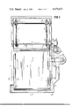
- FIG. 1 is a front view, partially broken away and partially in cross-section, of a guillotine valve of the present invention in the valve-closed position.
- FIG. 2 is an enlarged side view, along line 2--2, partially in cross-section and partially broken away, of the valve depicted in FIG. 1.
- FIG. 3 is a front view, along line 3--3, of the right-hand portion of the top seal assembly of the valve depicted in FIGS. 1 and 2.
- FIG. 4 depicts the top seal assembly in FIG. 2, but with the gate member completely withdrawn from the valve housing.
- FIG. 5 depicts the bottom seal assembly in FIG. 2, but with the valve in an intermediate position between fully open and fully closed.
- FIG. 6 is a top view, along line 6--6, of the side seal assembly of the valve depicted in FIGS. 1 and 2.
- FIG. 7 depicts the side seal assembly of FIG. 6, but in the valve-open position.
- FIG. 8 is an enlarged side view along line 8--8, partially broken away, of the valve depicted in FIG. 1.
- blade 10 is there shown fully inserted in housing 11. Between side edge 12 of blade 10 and interior wall 13 of housing 11, when in the valve-closed position, is a void space 14, which is separate from the upstream face 15 of blade 10 by the seal assembly indicated generally by reference numeral 16, and is separated from the downstream face 17 of blade 10 by the seal assembly indicated generally by reference numeral 18. Openings 19 through housing 11 serve to connect void space 14 with air duct 20, which is supplied with purge air by fan 21.
- the forward edge 22 of blade 10 protrudes between transverse spring sealing strips 23 which are J shaped in cross-section, the base of the J being biased against the upstream and downstream faces, 15 and 17, respectively, of blade 10.
- Seals 23, which are made of flexible shim stock, e.g., about 0.01 inch thick, and blade edge 22 are enclosed within air duct 20.
- blade 10 protrudes through blade withdrawal aperture 24, which is sealed to the atmosphere by transverse spring sealing strips 25.
- a second pair of transverse spring sealing strips 26 cooperates with strips 25 to form transverse void space 27, which is supplied with purge air by fan 21, hose 28, and pipe 29.
- Each ofthe side seal assemblies 16 and 18 is comprised of a U shaped channel formed by flange 30, edge member 31, and plate 33. Positioned lengthwise within the U shaped channel just described as a resiliently compressible rope (a so-called “tadpole seal”) 34, which, together with sealing strip 32, is held in place by plate 33, threaded stud 35, and nut 36. The resilience of rope 34 urges sealing strip 32 against blade 10.
- a so-called "tadpole seal” 34 Positioned lengthwise within the U shaped channel just described as a resiliently compressible rope (a so-called “tadpole seal”) 34, which, together with sealing strip 32, is held in place by plate 33, threaded stud 35, and nut 36. The resilience of rope 34 urges sealing strip 32 against blade 10.
- Raising and lowering of gate 10 is made possible by endless chains 37, attached by pendant rings (not shown) to the top of gate 10 and passing around sprockets 38 and 39.
- Sprockets 39 are turned by drive shaft 40, which is linked by gear reduction box 41 to manually operated wheel 42.
- a triangular opening 43 is formed by the forward edge 22 of blade 10 partially spreading apart opposed sealing strips 32. If air fan 21 is operating when the valve is in that position, any solids which have collected in void space 14 and air duct 20 are tossed up by the agitated air, and part of them are blown out of void space 14 through opening 43, thereby accomplishing a self-cleaning action.
- sealing strips 25 come together, as do sealing strips 26, thereby preventing the escape of conduit gases through pipe 29 and hose 28 to fan 21.
- bottom transverse sealing strips 23 are urged together upon withdrawal of gate 10 to seal against the escape of conduit gases through air duct 20 and past fan 21 to the atmosphere.
- side sealing strips 32 close upon one another when gate 10 is withdrawn from housing 11, also preventing the escape of conduit gases past fan 21 and into the atmosphere.
Abstract
Description
Claims (21)
Priority Applications (1)
| Application Number | Priority Date | Filing Date | Title |
|---|---|---|---|
| US05/862,133 US4176673A (en) | 1977-06-02 | 1977-12-19 | Purged sliding gate valve |
Applications Claiming Priority (2)
| Application Number | Priority Date | Filing Date | Title |
|---|---|---|---|
| US05/802,892 US4093245A (en) | 1977-06-02 | 1977-06-02 | Mechanical sealing means |
| US05/862,133 US4176673A (en) | 1977-06-02 | 1977-12-19 | Purged sliding gate valve |
Related Parent Applications (1)
| Application Number | Title | Priority Date | Filing Date |
|---|---|---|---|
| US05/802,892 Continuation-In-Part US4093245A (en) | 1977-06-02 | 1977-06-02 | Mechanical sealing means |
Publications (1)
| Publication Number | Publication Date |
|---|---|
| US4176673A true US4176673A (en) | 1979-12-04 |
Family
ID=27122505
Family Applications (1)
| Application Number | Title | Priority Date | Filing Date |
|---|---|---|---|
| US05/862,133 Expired - Lifetime US4176673A (en) | 1977-06-02 | 1977-12-19 | Purged sliding gate valve |
Country Status (1)
| Country | Link |
|---|---|
| US (1) | US4176673A (en) |
Cited By (20)
| Publication number | Priority date | Publication date | Assignee | Title |
|---|---|---|---|---|
| US4235256A (en) * | 1979-05-07 | 1980-11-25 | Cominco Ltd. | Damper assembly for gas duct |
| US4271860A (en) * | 1977-12-23 | 1981-06-09 | Alfa-Laval Ab | Valve |
| US4474205A (en) * | 1984-03-20 | 1984-10-02 | Ecolaire Incorporated | Sliding blade apparatus for closing conduits |
| US4491144A (en) * | 1983-07-08 | 1985-01-01 | Dreyer Paul L | Flexible seals for sliding blade dampers |
| US4561472A (en) * | 1984-03-20 | 1985-12-31 | Ecolaire Incorporated | Sliding blade closure apparatus with inflatable sealing ring |
| US4615505A (en) * | 1985-03-08 | 1986-10-07 | Environmental Elements Corp. | Fluid valve system |
| US4655241A (en) * | 1985-12-20 | 1987-04-07 | Damper Design, Inc. | Apparatus for sealing dampers |
| US4724863A (en) * | 1987-05-21 | 1988-02-16 | Connor Peter J | Flue gas seal |
| US4749168A (en) * | 1986-01-10 | 1988-06-07 | Pathway Bellows, Inc. | Damper plate sealing mechanism |
| EP0383186A1 (en) * | 1989-02-13 | 1990-08-22 | Bachmann Corporate Services, Inc. | Guillotine dampers with blade sealing means accommodative of thermal expansion forces |
| EP0481234A1 (en) * | 1990-10-19 | 1992-04-22 | VERWALTUNGS LOHSE GmbH & Co. KG | Slide gate for closing a pipeline |
| GB2290851A (en) * | 1994-06-29 | 1996-01-10 | Warman Int Ltd | Gate valve and liner therefor |
| US5711509A (en) * | 1996-07-01 | 1998-01-27 | Eltec Inc. | Isolation gate and frame assembly |
| US5890700A (en) * | 1997-07-29 | 1999-04-06 | The Clarkson Company | Gate valve |
| EP1555223A1 (en) | 2004-01-16 | 2005-07-20 | Renovac A/S | Valve, preferably for a waste suction system, and method for using the valve |
| US20050242316A1 (en) * | 2004-04-30 | 2005-11-03 | Senior Investments Ag | Rack and pinion wheel drive for an industrial sliding blade damper |
| US20050242318A1 (en) * | 2004-04-30 | 2005-11-03 | Senior Investments Ag | Seal cartridge for an industrial sliding blade damper |
| US20130203005A1 (en) * | 2011-08-24 | 2013-08-08 | Ikn Gmbh | Clinker kiln with slider for tertiary air duct |
| US20160145042A1 (en) * | 2013-07-30 | 2016-05-26 | Maricap Oy | Method and apparatus for feeding in and handling waste material |
| CN109114296A (en) * | 2018-09-13 | 2019-01-01 | 张翼翔 | A kind of irrigation control valve for northern anti-freeze |
Citations (5)
| Publication number | Priority date | Publication date | Assignee | Title |
|---|---|---|---|---|
| US2964036A (en) * | 1955-10-18 | 1960-12-13 | Amereng Dev Corp | Curtain dampers |
| US2996063A (en) * | 1960-06-23 | 1961-08-15 | Amereng Dev Corp | Curtain dampers |
| US3228389A (en) * | 1963-09-30 | 1966-01-11 | Thermo Technical Dev Ltd | Dampers |
| US4022241A (en) * | 1975-11-25 | 1977-05-10 | Air Clean Damper Co., Inc. | Damper sealing structure |
| US4093245A (en) * | 1977-06-02 | 1978-06-06 | Mosser Industries, Inc. | Mechanical sealing means |
-
1977
- 1977-12-19 US US05/862,133 patent/US4176673A/en not_active Expired - Lifetime
Patent Citations (5)
| Publication number | Priority date | Publication date | Assignee | Title |
|---|---|---|---|---|
| US2964036A (en) * | 1955-10-18 | 1960-12-13 | Amereng Dev Corp | Curtain dampers |
| US2996063A (en) * | 1960-06-23 | 1961-08-15 | Amereng Dev Corp | Curtain dampers |
| US3228389A (en) * | 1963-09-30 | 1966-01-11 | Thermo Technical Dev Ltd | Dampers |
| US4022241A (en) * | 1975-11-25 | 1977-05-10 | Air Clean Damper Co., Inc. | Damper sealing structure |
| US4093245A (en) * | 1977-06-02 | 1978-06-06 | Mosser Industries, Inc. | Mechanical sealing means |
Cited By (24)
| Publication number | Priority date | Publication date | Assignee | Title |
|---|---|---|---|---|
| US4271860A (en) * | 1977-12-23 | 1981-06-09 | Alfa-Laval Ab | Valve |
| US4235256A (en) * | 1979-05-07 | 1980-11-25 | Cominco Ltd. | Damper assembly for gas duct |
| US4491144A (en) * | 1983-07-08 | 1985-01-01 | Dreyer Paul L | Flexible seals for sliding blade dampers |
| US4474205A (en) * | 1984-03-20 | 1984-10-02 | Ecolaire Incorporated | Sliding blade apparatus for closing conduits |
| US4561472A (en) * | 1984-03-20 | 1985-12-31 | Ecolaire Incorporated | Sliding blade closure apparatus with inflatable sealing ring |
| US4615505A (en) * | 1985-03-08 | 1986-10-07 | Environmental Elements Corp. | Fluid valve system |
| US4655241A (en) * | 1985-12-20 | 1987-04-07 | Damper Design, Inc. | Apparatus for sealing dampers |
| US4749168A (en) * | 1986-01-10 | 1988-06-07 | Pathway Bellows, Inc. | Damper plate sealing mechanism |
| US4724863A (en) * | 1987-05-21 | 1988-02-16 | Connor Peter J | Flue gas seal |
| EP0383186A1 (en) * | 1989-02-13 | 1990-08-22 | Bachmann Corporate Services, Inc. | Guillotine dampers with blade sealing means accommodative of thermal expansion forces |
| EP0481234A1 (en) * | 1990-10-19 | 1992-04-22 | VERWALTUNGS LOHSE GmbH & Co. KG | Slide gate for closing a pipeline |
| GB2290851A (en) * | 1994-06-29 | 1996-01-10 | Warman Int Ltd | Gate valve and liner therefor |
| GB2290851B (en) * | 1994-06-29 | 1999-02-10 | Warman Int Ltd | Gate valve with spring assisted valve liner |
| US5711509A (en) * | 1996-07-01 | 1998-01-27 | Eltec Inc. | Isolation gate and frame assembly |
| US5890700A (en) * | 1997-07-29 | 1999-04-06 | The Clarkson Company | Gate valve |
| EP1555223A1 (en) | 2004-01-16 | 2005-07-20 | Renovac A/S | Valve, preferably for a waste suction system, and method for using the valve |
| US20050242316A1 (en) * | 2004-04-30 | 2005-11-03 | Senior Investments Ag | Rack and pinion wheel drive for an industrial sliding blade damper |
| US20050242318A1 (en) * | 2004-04-30 | 2005-11-03 | Senior Investments Ag | Seal cartridge for an industrial sliding blade damper |
| US7413163B2 (en) * | 2004-04-30 | 2008-08-19 | Senior Investments Ag | Rack and pinion wheel drive for an industrial sliding blade damper |
| US20130203005A1 (en) * | 2011-08-24 | 2013-08-08 | Ikn Gmbh | Clinker kiln with slider for tertiary air duct |
| US9121639B2 (en) * | 2011-08-24 | 2015-09-01 | Ikn Gmbh Ingenieurburo-Kuhlerbau-Neustadt | Clinker kiln with slider for tertiary air duct |
| US20160145042A1 (en) * | 2013-07-30 | 2016-05-26 | Maricap Oy | Method and apparatus for feeding in and handling waste material |
| US10773886B2 (en) * | 2013-07-30 | 2020-09-15 | Maricap Oy | Method and apparatus for feeding in and handling waste material |
| CN109114296A (en) * | 2018-09-13 | 2019-01-01 | 张翼翔 | A kind of irrigation control valve for northern anti-freeze |
Similar Documents
| Publication | Publication Date | Title |
|---|---|---|
| US4176673A (en) | Purged sliding gate valve | |
| US4093245A (en) | Mechanical sealing means | |
| US3698429A (en) | Gas tight isolators and valves | |
| US4077432A (en) | Purged valve | |
| US4163458A (en) | Device for sealing a conduit against the flow of liquid | |
| US4491144A (en) | Flexible seals for sliding blade dampers | |
| US3894481A (en) | Multi-blade damper | |
| US3504883A (en) | Sealing means for dampers and the like | |
| US4235256A (en) | Damper assembly for gas duct | |
| JPS6049010B2 (en) | Removable fluid seal | |
| US2875917A (en) | High temperature spring seal | |
| US3749115A (en) | Damper apparatus with fluid seal | |
| US4493311A (en) | Guillotine damper | |
| US4334550A (en) | Sealing means for sliding gate valve | |
| CA1059496A (en) | Ventilated poppet damper | |
| US2846999A (en) | Flue sealing means for use in conduits | |
| US7413163B2 (en) | Rack and pinion wheel drive for an industrial sliding blade damper | |
| US2988083A (en) | Flue sealing means for use in conduits having unidirectional gas flow | |
| US4278236A (en) | Slide valve for pipelines | |
| US4043534A (en) | Sealing means for sliding gate valve | |
| EP2431638B1 (en) | Sealing device and method | |
| US1733685A (en) | Gas valve | |
| US4338960A (en) | Guillotine type damper | |
| CN209540923U (en) | Double containment flue gas separates plate air door | |
| DE4233207A1 (en) | Ventilation valve |
Legal Events
| Date | Code | Title | Description |
|---|---|---|---|
| AS | Assignment |
Owner name: ECOLAIRE INCORPORATED, Free format text: MERGER;ASSIGNOR:MOSSER INDUSTRIES, INC.;REEL/FRAME:004321/0799 Effective date: 19800722 |
|
| AS | Assignment |
Owner name: CITIBANK,N.A. ,641 LEXINGTON AVENUE,NEW YORK,NEW Y Free format text: SECURITY INTEREST;ASSIGNOR:ECOLAIRE INCORPORATED;REEL/FRAME:004392/0727 |
|
| AS | Assignment |
Owner name: PHILADELPHIA NATIONAL BANK, THE, BROAD AND CHESTNU Free format text: SECURITY INTEREST;ASSIGNOR:ECOLAIRE INCORPORATED;REEL/FRAME:004458/0203 |
|
| AS | Assignment |
Owner name: ECOLAIRE INCORPORATED A PA CORP. Free format text: RELEASED BY SECURED PARTY;ASSIGNOR:CITIBANK, N.A.;REEL/FRAME:004455/0898 Effective date: 19850830 Owner name: ECOLAIRE PRIME, INC., A DE CORP. Free format text: RELEASED BY SECURED PARTY;ASSIGNOR:CITIBANK, N.A.;REEL/FRAME:004455/0898 Effective date: 19850830 |
|
| AS | Assignment |
Owner name: CITIBANK, N.A., 641 LEXINGTON, AVE., NEW YORK, NY Free format text: ASSIGNMENT OF ASSIGNORS INTEREST.;ASSIGNOR:ECOLAIRE INCORPORATED;REEL/FRAME:004749/0032 Effective date: 19870626 |
|
| AS | Assignment |
Owner name: ECOLAIRE INCORPORATED, A PA. CORP. Free format text: RELEASE OF PATENTS IN SECURITY AGREEMENT DATED AUGUST 30, 1985 REEL 4458 FRAMES 203-225;ASSIGNOR:PHILADELPHIA NATIONAL BANK, THE;REEL/FRAME:004813/0319 Effective date: 19870626 |
|
| AS | Assignment |
Owner name: ECOLAIRE INCORPORATED, A PA CORP., PENNSYLVANIA Free format text: RELEASED BY SECURED PARTY;ASSIGNOR:CITIBANK, N.A.;REEL/FRAME:005226/0137 Effective date: 19891011 |
|
| AS | Assignment |
Owner name: ECOLAIRE INCORPORATED A CORP. OF PA Free format text: RELEASED BY SECURED PARTY;ASSIGNOR:CITIBANK N.A.;REEL/FRAME:005173/0818 Effective date: 19891011 |
|
| AS | Assignment |
Owner name: JOY POWER PRODUCTS, INC., 1550 LEHIGH DRIVE, EASTO Free format text: ASSIGNMENT OF ASSIGNORS INTEREST.;ASSIGNOR:ECOLAIRE INCORPORATED;REEL/FRAME:005521/0599 Effective date: 19900724 |
|
| AS | Assignment |
Owner name: CONNECTICUT NATIONAL BANK, THE, STATELESS Free format text: SECURITY INTEREST;ASSIGNOR:ECOLAIRE INCORPORATED, A CORP. OF PA;REEL/FRAME:005670/0160 Effective date: 19901022 |
|
| AS | Assignment |
Owner name: CONNECTICUT NATIONAL BANK, CONNECTICUT Free format text: SECURITY INTEREST;ASSIGNOR:JOY POWER PRODUCTS, INC., A CORPORATION OF PA;REEL/FRAME:005951/0449 Effective date: 19911210 |