EP2562449A1 - Fluid circulation valve having an axial return spring - Google Patents
Fluid circulation valve having an axial return spring Download PDFInfo
- Publication number
- EP2562449A1 EP2562449A1 EP20120305997 EP12305997A EP2562449A1 EP 2562449 A1 EP2562449 A1 EP 2562449A1 EP 20120305997 EP20120305997 EP 20120305997 EP 12305997 A EP12305997 A EP 12305997A EP 2562449 A1 EP2562449 A1 EP 2562449A1
- Authority
- EP
- European Patent Office
- Prior art keywords
- shaft
- ring
- bearing
- valve according
- spring
- Prior art date
- Legal status (The legal status is an assumption and is not a legal conclusion. Google has not performed a legal analysis and makes no representation as to the accuracy of the status listed.)
- Granted
Links
Images

Classifications
-
- F—MECHANICAL ENGINEERING; LIGHTING; HEATING; WEAPONS; BLASTING
- F16—ENGINEERING ELEMENTS AND UNITS; GENERAL MEASURES FOR PRODUCING AND MAINTAINING EFFECTIVE FUNCTIONING OF MACHINES OR INSTALLATIONS; THERMAL INSULATION IN GENERAL
- F16K—VALVES; TAPS; COCKS; ACTUATING-FLOATS; DEVICES FOR VENTING OR AERATING
- F16K1/00—Lift valves or globe valves, i.e. cut-off apparatus with closure members having at least a component of their opening and closing motion perpendicular to the closing faces
- F16K1/16—Lift valves or globe valves, i.e. cut-off apparatus with closure members having at least a component of their opening and closing motion perpendicular to the closing faces with pivoted closure-members
- F16K1/18—Lift valves or globe valves, i.e. cut-off apparatus with closure members having at least a component of their opening and closing motion perpendicular to the closing faces with pivoted closure-members with pivoted discs or flaps
- F16K1/22—Lift valves or globe valves, i.e. cut-off apparatus with closure members having at least a component of their opening and closing motion perpendicular to the closing faces with pivoted closure-members with pivoted discs or flaps with axis of rotation crossing the valve member, e.g. butterfly valves
- F16K1/224—Details of bearings for the axis of rotation
-
- F—MECHANICAL ENGINEERING; LIGHTING; HEATING; WEAPONS; BLASTING
- F02—COMBUSTION ENGINES; HOT-GAS OR COMBUSTION-PRODUCT ENGINE PLANTS
- F02D—CONTROLLING COMBUSTION ENGINES
- F02D9/00—Controlling engines by throttling air or fuel-and-air induction conduits or exhaust conduits
- F02D9/04—Controlling engines by throttling air or fuel-and-air induction conduits or exhaust conduits concerning exhaust conduits
-
- F—MECHANICAL ENGINEERING; LIGHTING; HEATING; WEAPONS; BLASTING
- F02—COMBUSTION ENGINES; HOT-GAS OR COMBUSTION-PRODUCT ENGINE PLANTS
- F02D—CONTROLLING COMBUSTION ENGINES
- F02D9/00—Controlling engines by throttling air or fuel-and-air induction conduits or exhaust conduits
- F02D9/08—Throttle valves specially adapted therefor; Arrangements of such valves in conduits
- F02D9/10—Throttle valves specially adapted therefor; Arrangements of such valves in conduits having pivotally-mounted flaps
- F02D9/1035—Details of the valve housing
- F02D9/106—Sealing of the valve shaft in the housing, e.g. details of the bearings
-
- F—MECHANICAL ENGINEERING; LIGHTING; HEATING; WEAPONS; BLASTING
- F02—COMBUSTION ENGINES; HOT-GAS OR COMBUSTION-PRODUCT ENGINE PLANTS
- F02M—SUPPLYING COMBUSTION ENGINES IN GENERAL WITH COMBUSTIBLE MIXTURES OR CONSTITUENTS THEREOF
- F02M26/00—Engine-pertinent apparatus for adding exhaust gases to combustion-air, main fuel or fuel-air mixture, e.g. by exhaust gas recirculation [EGR] systems
- F02M26/65—Constructional details of EGR valves
- F02M26/70—Flap valves; Rotary valves; Sliding valves; Resilient valves
-
- F—MECHANICAL ENGINEERING; LIGHTING; HEATING; WEAPONS; BLASTING
- F16—ENGINEERING ELEMENTS AND UNITS; GENERAL MEASURES FOR PRODUCING AND MAINTAINING EFFECTIVE FUNCTIONING OF MACHINES OR INSTALLATIONS; THERMAL INSULATION IN GENERAL
- F16K—VALVES; TAPS; COCKS; ACTUATING-FLOATS; DEVICES FOR VENTING OR AERATING
- F16K1/00—Lift valves or globe valves, i.e. cut-off apparatus with closure members having at least a component of their opening and closing motion perpendicular to the closing faces
- F16K1/16—Lift valves or globe valves, i.e. cut-off apparatus with closure members having at least a component of their opening and closing motion perpendicular to the closing faces with pivoted closure-members
- F16K1/18—Lift valves or globe valves, i.e. cut-off apparatus with closure members having at least a component of their opening and closing motion perpendicular to the closing faces with pivoted closure-members with pivoted discs or flaps
- F16K1/22—Lift valves or globe valves, i.e. cut-off apparatus with closure members having at least a component of their opening and closing motion perpendicular to the closing faces with pivoted closure-members with pivoted discs or flaps with axis of rotation crossing the valve member, e.g. butterfly valves
- F16K1/226—Shaping or arrangements of the sealing
- F16K1/2268—Sealing means for the axis of rotation
-
- F—MECHANICAL ENGINEERING; LIGHTING; HEATING; WEAPONS; BLASTING
- F02—COMBUSTION ENGINES; HOT-GAS OR COMBUSTION-PRODUCT ENGINE PLANTS
- F02B—INTERNAL-COMBUSTION PISTON ENGINES; COMBUSTION ENGINES IN GENERAL
- F02B3/00—Engines characterised by air compression and subsequent fuel addition
- F02B3/06—Engines characterised by air compression and subsequent fuel addition with compression ignition
-
- Y—GENERAL TAGGING OF NEW TECHNOLOGICAL DEVELOPMENTS; GENERAL TAGGING OF CROSS-SECTIONAL TECHNOLOGIES SPANNING OVER SEVERAL SECTIONS OF THE IPC; TECHNICAL SUBJECTS COVERED BY FORMER USPC CROSS-REFERENCE ART COLLECTIONS [XRACs] AND DIGESTS
- Y02—TECHNOLOGIES OR APPLICATIONS FOR MITIGATION OR ADAPTATION AGAINST CLIMATE CHANGE
- Y02T—CLIMATE CHANGE MITIGATION TECHNOLOGIES RELATED TO TRANSPORTATION
- Y02T10/00—Road transport of goods or passengers
- Y02T10/10—Internal combustion engine [ICE] based vehicles
- Y02T10/12—Improving ICE efficiencies
Definitions
- the present invention relates to a fluid circulation valve, intended to equip internal combustion engines, whether gasoline or diesel, vehicles.
- valves that are the subject of the invention can be provided on the exhaust line of diesel engines, in particular for the purpose of treating nitrogen oxides (NOx) by redirecting a part of the exhaust gases in the intake line, and are commonly referred to as "EGR valve". Or they can also be provided upstream on the engine intake line by then dosing the air intake into it.
- EGR valve nitrogen oxides
- Other applications of the valve in engines or other fluid circulation systems (gaseous or liquid) could be envisaged without departing from the scope of the invention.
- the rotational control of the shaft makes it possible to adjust the flow rate of the fluid flowing in the conduit of the valve according to the angular position given to the flap and, in the case of the EGR valve, to take a part of the exhaust gas to redirect it to the engine intake line according to the engine speed in the presence.
- the return spring it allows to close primarily the valve (the flap of the shaft closing the duct) in case of electrical malfunction of the valve.
- the axial locking of the rotary control shaft is provided by a U-shaped washer introduced, following the arrangement of a bearing, in grooves in the body and the shaft, or by fitting a ball bearing housed in a receiving hole of the body and carrying the shaft.
- the ball bearing solution requires, in turn, a complex assembly tool and entails a significant cost.
- the object of the present invention is to overcome these drawbacks and concerns a fluid circulation valve whose design of the axial blocking guarantees the use of the valve's operating reliability even in the event of the presence of a return spring. .
- the fluid circulation valve for example EGR, as defined previously is remarkable, according to the invention, in that the axial locking of the shaft is obtained by at least one cylindrical ring mounted to rotate on said shaft and having an outer surface facing one of the bearings and contacting a transverse face thereof.
- the ring directly acts as an axial stop for the shaft being in contact with the corresponding bearing.
- the realization of the valves is simplified by the removal of the receiving grooves (and therefore sharp edges generating hard points and wear) of the anterior washers or the removal of ball bearings and the associated assembly tooling, This makes the valve more reliable and reduces manufacturing costs.
- the invention makes it possible to achieve an axial stop of the rotary shaft of the valve limiting the friction and the resulting wear.
- the ring has a radial collar defining said outer surface facing the bearing and coming into contact with the transverse face thereof.
- the outer radial flange makes it possible to offer a large contact surface with the transverse face of the bearing, so that the axial force of the spring is distributed more evenly over this contact surface which, consequently, contributes to reducing the wear.
- the bearings are made of a low friction material, the wear is reduced, or almost non-existent, during the repeated operation of the rotary shaft, even in the case of action of a return spring. This eliminates the appearance of hard points and axial play.
- the flange of the ring is applied directly against a corresponding flange terminating the transverse face of the bearing, under the action of said spring.
- a large contact area is obtained, helping to optimize the distribution of the axial force of the spring and reduce wear.
- a washer may be arranged facing the other bearing, between the shaft and the body, for the axial locking of the shaft in the opposite direction to the action of the spring.
- a simple washer is sufficient since it is used in particular for mounting the shaft and is finally almost not solicited during operation of the valve because the permanent force of the spring is effected in the opposite direction, with the ring .
- the flange of the ring engages in a countersink formed in the corresponding transverse face of said bearing.
- the bearing housed in said passage, with the radial flange of the ring which is received, with a functional clearance, in the counterbore of the bearing while coming into axial abutment, on one side, with the bottom of the countersink, in the direction of action of the spring, or, on the other side, with a part of the body delimiting the passage in the opposite direction.
- This embodiment eliminates the previous washer because the collar of the ring itself is caught between the bottom of the counterbore and the body serving as axial abutments in both directions.
- the flange of the ring engages in a counterbore formed in the body of the valve.
- the bearing is then mounted on the shaft vis-à-vis the ring, while the flange engages, with axial functional play, in the counterbore of a hole for receiving the ring , formed in a part of the body which delimits the passage, so that the collar can abut, on one side, with the bearing in the direction of action of the spring or, on the other side, with the bottom of the countersink of the body, in the other direction.
- said ring is integral in rotation with the shaft by fitting, welding or other, and the bearings are mounted by tight fit, such as by fitting, in the passage of the body.
- the ring is made of a material compatible with the bearing material and, as examples, the bearings are made of stainless steel or cupro-nickel copper bronze alloys.
- the bearings can be straight, that is to say, be without rounded support parts.
- Each bearing can be obtained otherwise than by overmolding.
- Each bearing can be contained in the body, that is to say that each bearing does not protrude outwardly beyond the outer contour of the body.
- the body can be monobloc.
- the stop ring and the spring may not be in contact with each other.
- the spring is for example disposed at the end of the shaft opposite to that near which is disposed the ring.
- the washer can be configured to allow a two-sided stop of the shaft.
- the fluid circulation valve 1 shown in the figure 1 is, for example, the exhaust gas recirculation valve of an engine, the purpose of which has been recalled previously, but the invention is not limited to this type of valve and generally relates to rotary drive shaft valves of the shutter (shutter) subjected to the action of a return spring.
- the valve 1 comprises, in the usual way, a body 2 inside which is formed a longitudinal duct 3, and which is intended to be mounted, via fittings, on a bypass of the engine exhaust line so that the part of the exhaust gas flowing in this bypass passes through the duct and is deflected towards the intake line to be burned again by the engine.
- the connections and the exhaust and intake lines have not been shown, being well known in themselves and not part of the invention.
- a rotary control shaft 4 with, integral with it, a shutter 5 of the shutter type, the duct 3, two bearings 6, 7 for the rotary movement of the shaft 4 relative to its geometric axis A, a return spring 8 exerting a force on the shaft in a direction along the axis, and an axial locking of the shaft 4.
- two aligned holes 9A, 9B are formed in the body 2, perpendicularly to the longitudinal duct 3 passing diametrically through it, to form a passage 10 of circular section, and receive respectively the two bearings 6, 7.
- These fixed bearings 6, 7 are made of a material that provides self-lubricating and anticorrosive properties suitable for providing enhanced durability. For this, they can be made of an alloy of copper and nickel or tin, or a stainless steel.
- control shaft 4 which can thus pivot freely around the axis A, by a sliding fit provided between the shaft and the bearings.
- the end 11 of the shaft described as inferior to the figure 1 , engages in the corresponding bearing 6, while the other upper end 12 through the other bearing 7 and opens outwardly of the body 2 of the valve 1 to be connected to the actual control of the shaft 4 , not shown on the figure 1 because of a usual type in itself.
- the flap At the control shaft 4 is connected in rotation the shutter 5 by fasteners 14, by welding, or other, which allows the flap to rotate with the shaft between two extreme positions, one of which , fully open (the plane of the flap being in the direction of gas flow, as on the figure 1 ), passes the part of the exhaust gas diverted, and the other, closed against the side wall of the duct 3, possibly via a seal not shown (the plane of the flap being perpendicular to the direction of flow of the gases) , figure 1 ).
- the axial locking of the shaft 4 is obtained, in the first embodiment illustrated in FIG. figure 1 , by a cylindrical ring 15 directly mounted on the shaft and provided with an outer radial flange 16 which has a surface 20 coming into contact with the bearing 6 as a result of the action of the return spring 8 (arrow F). And also, in the opposite direction to the action of the spring, by a washer 17 mounted on the shaft 4 and located on the side of the other bearing 7, as will be seen later.
- the cylindrical ring 15 is secured to the end 11 of the shaft 4 by fitting which immobilizes it in rotation and in translation relative to the shaft in the chosen position. Any other way to ensure such a link could be considered.
- the radial flange 16 terminating one end of the ring 15 is intended to be applied directly against an outer radial flange 18 also terminating the plain bearing 6 which is housed in the hole of the passage 9A and which, in turn, bears the end 11 of the tree.
- the ring 15 acts as an axial stop for the shaft 4 in the direction of the axial force F exerted by the spring 8, along the axis A, and that the contact between the ring 15 and the bearing 6 is established directly by the outer transverse faces 20, 21 of their respective flanges 16, 18, on a large area or contact surface.
- the washer 17 acting as an axial stop in the direction opposite to the direction F along the axis A, it is in the form of a U mounted in a peripheral groove 25 of the end 12 of the shaft and is applied in a enlargement 26 of the hole 9B of the passage, at the end of the end of the shaft and at a distance from the bearing 7.
- the U-shaped washer 17 is only in contact with the body 2 in order to axially stop the shaft 4 in this direction.
- the bearing 7 is simply of constant annular shape and that the washer is turned towards the control of the valve 7.
- this U-shaped washer 17 serves in particular as an axial stop for mounting in the direction opposite to F, it does not is not subjected to the action of the spring 8 during operation of the valve and, therefore, to any wear, unlike the ring 15 acting as axial axial stop in the direction F.
- this ring is subjected to the permanent action of the spring and, thanks to its mounting without machining on the rotary shaft 4 and the radial flange 16 to contact surface 20 important directly with the low friction bearing, it can support the rotations of the shutter of the shaft during valve operation, avoiding problems of friction and wear.
- a functional axial clearance between the ring 15 and its bearing 6 is adjusted by a mounting tool during the fitting of the ring on the shaft.
- this functional clearance J disappears under the action of the spring 8 pulling axially on the shaft 4 sliding in the bearings, and is then between the ring 15 (flush with the transverse face of the 11 end of the shaft 4) and a portion 27 of the body in the form of plug 28 closing the passage 10.
- the cylindrical ring 15 with external radial collar 16 is integral with the rotary shaft 4, in the same way as above, but one of the bearings, for example the bearing 6 by analogy with the previous figure, is in turn mounted on the ring 15.
- the bearing 6 is fitted into the hole 9A of the passage 10, so that it is immobilized in position relative to the body 2, while the ring 15, integral with the shaft 4, is mounted by a sliding fit in the bearing 6, to slide and pivot relative thereto.
- the flange 16 is then received in a countersink 30 which is formed in the transverse end face 31 of the bearing and which serves as flange 18 of the bearing.
- the depth P of the counterbore is greater than the thickness E of the collar 16 so as to create by difference the axial clearance J.
- the face 31 bears against the portion, in this case flange, 27 of the body, to complete the passage 10.
- the flange 16 of the ring 15, when the shaft 4 is not subjected to the action of the spring 8, can be applied against this flange 27.
- the bottom 32 of the counterbore and the rim 27 of the body serve as functional axial abutments for the collar ring 15 and, consequently, for the rotary shaft 4, eliminating the need for a presence of the washer 17. in the previous embodiment.
- the ring 15 and the collar 16 provide the same functions and advantages as before, that is to say a distribution of the spring force over a large area or contact area and less wear, or almost zero , by its direct contact with the self-lubricated low-friction bearing, during the rotation of the shaft flap when the valve operates.
- the third embodiment illustrated with reference to the figure 3 is of design close to the second realization.
- the flange 16 of the ring 15 is housed, not in a countersink of the bearing, but in a countersink 34 provided in the flange 27 of the body.
- This countersink 34 terminates the through hole 35 of the surrounding body the lower end 11 of the shaft 4, and receives the ring 15.
- the bearing 6 is mounted around the shaft 4, as in the first mode ( figure 1 ), so that the ring 15 no longer provides the additional function of guiding the shaft, but its main function of axial locking thereof, this time in both directions with respect to the axis A.
- the ring is of reduced axial length compared to its realization of the figure 2 .
- a second cylindrical ring 15 may be provided in contact with the other bearing 7, in particular if the shaft is strongly axially stressed both in the direction of arrow F and in the opposite direction.
Abstract
Description
La présente invention concerne une vanne de circulation de fluide, destinée à équiper les moteurs à combustion interne, qu'ils soient à essence ou Diesel, de véhicules.The present invention relates to a fluid circulation valve, intended to equip internal combustion engines, whether gasoline or diesel, vehicles.
Plus particulièrement, quoique non exclusivement, les vannes objet de l'invention peuvent être prévues sur la ligne d'échappement des moteurs Diesel notamment à des fins de traitement des oxydes d'azote (NOx) en redirigeant une partie des gaz d'échappement dans la ligne d'admission, et sont désignées communément « vanne EGR ». Ou elles peuvent également être prévues en amont sur la ligne d'admission du moteur en dosant alors l'admission d'air dans celui-ci. D'autres applications de la vanne dans des moteurs ou autres installations à circulation de fluide (gazeux ou liquide) pourraient être envisagées sans sortir du cadre de l'invention.More particularly, although not exclusively, the valves that are the subject of the invention can be provided on the exhaust line of diesel engines, in particular for the purpose of treating nitrogen oxides (NOx) by redirecting a part of the exhaust gases in the intake line, and are commonly referred to as "EGR valve". Or they can also be provided upstream on the engine intake line by then dosing the air intake into it. Other applications of the valve in engines or other fluid circulation systems (gaseous or liquid) could be envisaged without departing from the scope of the invention.
Il est connu des vannes permettant de régler le débit d'un fluide comprenant :
- un corps à conduit traversant pour le fluide,
- un arbre de commande rotatif entraînant un volet obturateur du conduit, ledit arbre étant monté dans un passage du corps communiquant avec le conduit, ledit arbre étant soumis à l'action d'un ressort de rappel prévu entre le corps et l'arbre,
- des paliers en matériau à faible frottement prévus dans ledit passage entre le corps et l'arbre de commande rotatif, et
- un blocage axial de l'arbre dans ledit corps.
- a through-conduit body for the fluid,
- a rotary control shaft driving a flap shutter of the duct, said shaft being mounted in a passage of the body communicating with the duct, said shaft being subjected to the action of a return spring provided between the body and the shaft,
- low-friction material bearings provided in said passage between the body and the rotary control shaft, and
- an axial locking of the shaft in said body.
Ainsi, la commande en rotation de l'arbre permet de régler le débit du fluide circulant dans le conduit de la vanne selon la position angulaire donnée au volet et, dans le cas de la vanne EGR, de prélever une partie des gaz d'échappement pour la rediriger vers la ligne d'admission du moteur selon le régime moteur en présence. Quant au ressort de rappel, il permet de fermer prioritairement la vanne (le volet de l'arbre venant obturer le conduit) en cas de dysfonctionnement électrique de la vanne.Thus, the rotational control of the shaft makes it possible to adjust the flow rate of the fluid flowing in the conduit of the valve according to the angular position given to the flap and, in the case of the EGR valve, to take a part of the exhaust gas to redirect it to the engine intake line according to the engine speed in the presence. As for the return spring, it allows to close primarily the valve (the flap of the shaft closing the duct) in case of electrical malfunction of the valve.
Généralement, le blocage axial de l'arbre rotatif de commande est assuré par une rondelle en U introduite, suite à l'agencement d'un palier, dans des gorges ménagées dans le corps et l'arbre, ou encore par emmanchement d'un roulement à billes logé dans un trou de réception du corps et portant l'arbre.Generally, the axial locking of the rotary control shaft is provided by a U-shaped washer introduced, following the arrangement of a bearing, in grooves in the body and the shaft, or by fitting a ball bearing housed in a receiving hole of the body and carrying the shaft.
Ces blocages axiaux présentent cependant des défauts, en particulier pour les vannes dont le volet est très fréquemment utilisé comme les vannes EGR.These axial blockages, however, have defects, in particular for valves whose flap is very frequently used as the EGR valves.
En effet, par suite de l'effort axial exercé sur l'arbre par le ressort et du fonctionnement répété et soutenu de la vanne aux régimes moteur concernés, il apparaît, à l'usage, une usure entre la rondelle en U et l'arbre au niveau de la gorge correspondante et, donc, des points durs lors de la rotation de l'arbre sur la rondelle pouvant entraîner des blocages intempestifs du volet, ainsi qu'un jeu axial provoquant alors un contact non souhaité entre le volet et le conduit.Indeed, as a result of the axial force exerted on the shaft by the spring and the repeated and sustained operation of the valve engine speeds concerned, it appears, in use, a wear between the washer U and the shaft at the corresponding groove and, therefore, hard points during the rotation of the shaft on the washer can cause inadvertent blocking of the flap, and an axial play then causing undesired contact between the flap and the leads.
Par ailleurs, la solution par roulement à billes nécessite, quant à elle, un outillage de montage complexe et entraîne un coût significatif.In addition, the ball bearing solution requires, in turn, a complex assembly tool and entails a significant cost.
La présente invention a pour but de remédier à ces inconvénients et concerne une vanne de circulation de fluide dont la conception du blocage axial garantit à l'usage une fiabilité de fonctionnement de la vanne et ceci même en cas de présence d'un ressort de rappel.The object of the present invention is to overcome these drawbacks and concerns a fluid circulation valve whose design of the axial blocking guarantees the use of the valve's operating reliability even in the event of the presence of a return spring. .
A cet effet, la vanne de circulation de fluide, par exemple EGR, telle que définie préalablement est remarquable, selon l'invention, par le fait que le blocage axial de l'arbre est obtenu par au moins une bague cylindrique montée solidaire en rotation sur ledit arbre et présentant une surface externe tournée vers l'un des paliers et venant au contact d'une face transversale de celui-ci.For this purpose, the fluid circulation valve, for example EGR, as defined previously is remarkable, according to the invention, in that the axial locking of the shaft is obtained by at least one cylindrical ring mounted to rotate on said shaft and having an outer surface facing one of the bearings and contacting a transverse face thereof.
Ainsi, grâce à l'invention, la bague fait directement office de butée axiale pour l'arbre en étant au contact du palier correspondant. Par ailleurs, la réalisation des vannes est simplifiée par la suppression des gorges de réception (et donc des arêtes vives génératrices de points durs et d'usure) des rondelles antérieures ou la suppression des roulements à billes et de l'outillage de montage associé, ce qui permet de fiabiliser la vanne et de diminuer les coûts de fabrication. Au final, l'invention permet de réaliser un arrêt axial de l'arbre rotatif de la vanne limitant le frottement et l'usure qui en découle.Thus, thanks to the invention, the ring directly acts as an axial stop for the shaft being in contact with the corresponding bearing. Furthermore, the realization of the valves is simplified by the removal of the receiving grooves (and therefore sharp edges generating hard points and wear) of the anterior washers or the removal of ball bearings and the associated assembly tooling, This makes the valve more reliable and reduces manufacturing costs. Finally, the invention makes it possible to achieve an axial stop of the rotary shaft of the valve limiting the friction and the resulting wear.
Un tel résultat est avantageusement obtenu lorsque ledit arbre est soumis à l'action d'un ressort de rappel, prévu entre le corps et l'arbre. La bague vient alors au contact de la face transversale du palier concerné dans le sens du rappel axial auquel est soumis l'arbre par ledit ressort.Such a result is advantageously obtained when said shaft is subjected to the action of a return spring provided between the body and the shaft. The ring then comes into contact with the transverse face of the bearing concerned in the direction of the axial return to which the shaft is subjected by said spring.
De préférence, la bague présente une collerette radiale définissant ladite surface externe tournée vers le palier et venant au contact de la face transversale de celui-ci. Ainsi, la collerette radiale externe permet d'offrir une grande surface de contact avec la face transversale du palier, de sorte que l'effort axial du ressort est davantage réparti sur cette surface de contact ce qui, par conséquent, contribue à réduire l'usure. Comme les paliers sont réalisés en un matériau à faible frottement, l'usure est réduite, voire quasi inexistante, lors du fonctionnement répété de l'arbre rotatif, ceci même en cas d'action d'un ressort de rappel. On supprime de la sorte l'apparition des points durs et du jeu axial.Preferably, the ring has a radial collar defining said outer surface facing the bearing and coming into contact with the transverse face thereof. Thus, the outer radial flange makes it possible to offer a large contact surface with the transverse face of the bearing, so that the axial force of the spring is distributed more evenly over this contact surface which, consequently, contributes to reducing the wear. As the bearings are made of a low friction material, the wear is reduced, or almost non-existent, during the repeated operation of the rotary shaft, even in the case of action of a return spring. This eliminates the appearance of hard points and axial play.
Dans un mode de réalisation, la collerette de la bague s'applique directement contre une collerette correspondante terminant la face transversale du palier, sous l'action dudit ressort. Ainsi, une zone de contact importante est obtenue, contribuant à optimiser la répartition de l'effort axial du ressort et à réduire l'usure.In one embodiment, the flange of the ring is applied directly against a corresponding flange terminating the transverse face of the bearing, under the action of said spring. Thus, a large contact area is obtained, helping to optimize the distribution of the axial force of the spring and reduce wear.
Une rondelle pourra être agencée en regard de l'autre palier, entre l'arbre et le corps, pour le blocage axial de l'arbre dans le sens opposé à l'action du ressort. Une simple rondelle suffit puisque celle-ci sert notamment au montage de l'arbre et n'est finalement quasiment pas sollicitée lors du fonctionnement de la vanne du fait que l'effort permanent du ressort s'effectue dans le sens opposé, avec la bague.A washer may be arranged facing the other bearing, between the shaft and the body, for the axial locking of the shaft in the opposite direction to the action of the spring. A simple washer is sufficient since it is used in particular for mounting the shaft and is finally almost not solicited during operation of the valve because the permanent force of the spring is effected in the opposite direction, with the ring .
Dans un autre mode de réalisation, la collerette de la bague s'engage dans un lamage ménagé dans la face transversale correspondante dudit palier.In another embodiment, the flange of the ring engages in a countersink formed in the corresponding transverse face of said bearing.
Par exemple, autour de la bague solidaire de l'arbre rotatif, est monté le palier logé dans ledit passage, avec la collerette radiale de la bague qui est reçue, avec un jeu fonctionnel, dans le lamage du palier en venant en butée axiale, d'un côté, avec le fond du lamage, dans le sens de l'action du ressort, ou, de l'autre côté, avec une partie du corps délimitant le passage dans le sens opposé. Cette réalisation s'affranchit de la rondelle précédente du fait que la collerette de la bague elle-même se trouve prise entre le fond du lamage et le corps servant de butées axiales dans les deux sens.For example, around the ring integral with the rotary shaft, is mounted the bearing housed in said passage, with the radial flange of the ring which is received, with a functional clearance, in the counterbore of the bearing while coming into axial abutment, on one side, with the bottom of the countersink, in the direction of action of the spring, or, on the other side, with a part of the body delimiting the passage in the opposite direction. This embodiment eliminates the previous washer because the collar of the ring itself is caught between the bottom of the counterbore and the body serving as axial abutments in both directions.
Dans encore un autre mode de réalisation, la collerette de la bague s'engage dans un lamage ménagé dans le corps de la vanne.In yet another embodiment, the flange of the ring engages in a counterbore formed in the body of the valve.
Par exemple, le palier est alors monté sur l'arbre en vis-à-vis de la bague, tandis que la collerette s'engage, avec un jeu fonctionnel axial, dans le lamage d'un trou de passage de réception de la bague, ménagé dans une partie du corps qui délimite le passage, de sorte que la collerette peut venir en butée, d'un côté, avec le palier dans le sens de l'action du ressort ou, de l'autre côté, avec le fond du lamage du corps, dans l'autre sens.For example, the bearing is then mounted on the shaft vis-à-vis the ring, while the flange engages, with axial functional play, in the counterbore of a hole for receiving the ring , formed in a part of the body which delimits the passage, so that the collar can abut, on one side, with the bearing in the direction of action of the spring or, on the other side, with the bottom of the countersink of the body, in the other direction.
De préférence, ladite bague est solidaire en rotation de l'arbre par emmanchement, soudage ou autre, et les paliers sont montés par ajustement serré, tel que par emmanchement, dans le passage du corps.Preferably, said ring is integral in rotation with the shaft by fitting, welding or other, and the bearings are mounted by tight fit, such as by fitting, in the passage of the body.
Pour minimiser encore les frottements, la bague est réalisée en un matériau compatible avec le matériau du palier et, à titre d'exemples, les paliers sont réalisés en acier inoxydable ou en des alliages de cuivre du type cupro-nickel, bronze.To further minimize friction, the ring is made of a material compatible with the bearing material and, as examples, the bearings are made of stainless steel or cupro-nickel copper bronze alloys.
Les paliers peuvent être droits, c'est-à-dire être dépourvus de parties d'appui arrondies.The bearings can be straight, that is to say, be without rounded support parts.
Chaque palier peut être obtenu autrement que par surmoulage.Each bearing can be obtained otherwise than by overmolding.
Chaque palier peut être contenu dans le corps, c'est-à-dire que chaque palier ne fait pas saillie extérieurement au-delà du contour extérieur du corps. Le corps peut être monobloc.Each bearing can be contained in the body, that is to say that each bearing does not protrude outwardly beyond the outer contour of the body. The body can be monobloc.
La bague d'arrêt et le ressort peuvent ne pas être en contact l'un avec l'autre. Le ressort est par exemple disposé au niveau de l'extrémité de l'arbre opposée à celle à proximité de laquelle est disposée la bague.The stop ring and the spring may not be in contact with each other. The spring is for example disposed at the end of the shaft opposite to that near which is disposed the ring.
La rondelle peut être configurée de manière à permettre un arrêt bilatéral de l'arbre.The washer can be configured to allow a two-sided stop of the shaft.
La vanne peut être une vanne EGR ou un doseur, par exemple.
- Les figures annexées feront bien comprendre comment l'invention peut être réalisée. Sur ces figures, des références identiques désignent des éléments semblables.
- La
figure 1 est une coupe transversale partielle d'un exemple de réalisation d'une vanne de circulation de fluide à ressort de rappel avec, conformément à l'invention, le blocage axial de l'arbre de commande rotatif de la vanne selon un premier mode de réalisation. - La
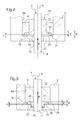
figure 2 montre, en coupe transversale, le blocage axial de l'arbre de commande rotatif de la vanne selon un deuxième mode de réalisation. - La
figure 3 montre, en coupe transversale, le blocage axial de l'arbre de commande rotatif de la vanne selon un troisième mode de réalisation.
- The appended figures will make it clear how the invention can be realized. In these figures, identical references designate similar elements.
- The
figure 1 is a partial cross section of an exemplary embodiment of a spring return fluid circulation valve with, according to the invention, the axial locking of the rotary control shaft of the valve according to a first embodiment . - The
figure 2 shows, in cross section, the axial locking of the rotary control shaft of the valve according to a second embodiment. - The
figure 3 shows, in cross section, the axial locking of the rotary control shaft of the valve according to a third embodiment.
La vanne de circulation de fluide 1 représentée sur la
La vanne 1 comprend, de façon usuelle, un corps 2 à l'intérieur duquel est ménagé un conduit longitudinal 3, et qui est destiné à être monté, par l'intermédiaire de raccords, sur une dérivation de la ligne d'échappement du moteur de manière que la partie des gaz d'échappement circulant dans cette dérivation traverse le conduit et soit déviée vers la ligne d'admission pour être à nouveau brûlée par le moteur. Les raccords et les lignes d'échappement et d'admission n'ont pas été représentés, étant bien connus en eux-mêmes et ne faisant pas partie de l'invention.The
Dans le corps 2 de la vanne 1, issu généralement de fonderie, sont reçus principalement un arbre de commande rotatif 4 avec, solidaire de celui-ci, un obturateur 5 du type à volet, du conduit 3, deux paliers 6, 7 pour le mouvement rotatif de l'arbre 4 par rapport à son axe géométrique A, un ressort de rappel 8 exerçant un effort sur l'arbre dans un sens selon l'axe, et un blocage axial de l'arbre 4.In the
Plus particulièrement, deux trous alignés 9A, 9B sont ménagés dans le corps 2, perpendiculairement au conduit longitudinal 3 en passant diamétralement par celui-ci, pour former un passage 10 de section circulaire, et reçoivent respectivement les deux paliers 6, 7. Ceux-ci sont cylindriques de section annulaire et sont, dans cet exemple, montés à force dans les trous 9A, 9B de façon à être immobilisés en position (en rotation et en translation) par rapport au corps 2 de la vanne. Ces paliers fixes 6, 7 sont réalisés en un matériau qui leur assure des propriétés autolubrifiantes et anticorrosives appropriées procurant une longévité renforcée. Pour cela, ils peuvent être en un alliage de cuivre et de nickel ou d'étain, ou en un acier inoxydable.More particularly, two aligned
Dans ces deux paliers 6, 7 est reçu l'arbre de commande 4 qui peut ainsi pivoté librement autour de l'axe A, par un ajustement glissant prévu entre l'arbre et les paliers. L'extrémité 11 de l'arbre, qualifiée d'inférieure par rapport à la
A l'arbre de commande 4 est lié en rotation le volet d'obturation 5 par des organes de fixation 14, par soudage, ou autre, ce qui permet au volet de pouvoir tourner avec l'arbre entre deux positions extrêmes dont l'une, ouverte totalement (le plan du volet étant dans le sens de circulation des gaz, comme sur la
Conformément à l'invention, le blocage axial de l'arbre 4 est obtenu, dans le premier mode de réalisation illustré sur la
En particulier, la bague cylindrique 15 est solidarisée de l'extrémité 11 de l'arbre 4 par emmanchement ce qui l'immobilise en rotation et en translation par rapport à l'arbre dans la position choisie. Tout autre moyen pour assurer une telle liaison pourrait être envisagé. La collerette radiale 16 terminant une extrémité de la bague 15 est destinée à s'appliquer directement contre une collerette radiale externe 18 terminant également le palier lisse 6 qui est logé dans le trou du passage 9A et qui porte, à son tour, l'extrémité 11 de l'arbre. On comprend donc que la bague 15 fait office de butée axiale pour l'arbre 4 dans le sens de l'effort axial F exercé par le ressort 8, selon l'axe A, et que le contact entre la bague 15 et le palier 6 s'établit directement par les faces transversales externes 20, 21 de leurs collerettes respectives 16, 18, sur une zone ou surface de contact importante.In particular, the
De la sorte, l'effort axial engendré par le ressort se répartit sur cette grande zone de contact qui répond donc aux exigences souhaitées puisque le contact s'effectue de façon privilégié sur celle-ci par suite de l'action permanente du ressort durant la vie de la vanne. En outre, comme le palier 6 est en un matériau à faible frottement et que la bague 15 est en un matériau compatible avec le palier, voire identique à celui-ci, l'usure est quasi inexistante.In this way, the axial force generated by the spring is distributed over this large contact area which therefore meets the desired requirements since the contact is effected in a preferred manner on the latter as a result of the permanent action of the spring during the life of the valve. In addition, since the
A propos du ressort 8, on voit, sur la
Concernant la rondelle 17 faisant office de butée axiale dans le sens opposé au sens F selon l'axe A, elle se présente sous forme de U montée dans une gorge périphérique 25 de l'extrémité 12 de l'arbre et s'applique dans un élargissement 26 du trou 9B du passage, en bout de l'extrémité de l'arbre et à distance du palier 7.Concerning the
Ainsi, la rondelle 17 en U est seulement en contact avec le corps 2 afin de réaliser l'arrêt axial de l'arbre 4 dans ce sens. On remarque que le palier 7 est simplement de forme annulaire constante et que la rondelle est tournée vers la commande de la vanne 7. Comme cette rondelle 17 en U fait office notamment de butée axiale de montage dans le sens opposé à F, elle n'est pas soumise à l'action du ressort 8 durant le fonctionnement de la vanne et, donc, à une quelconque usure, contrairement à la bague 15 faisant office de butée axiale fonctionnelle dans le sens F. En effet, comme déjà dit, cette bague est soumise à l'action permanente du ressort et, grâce à son montage sans usinage sur l'arbre rotatif 4 et à la collerette radiale 16 à surface de contact 20 importante directement avec le palier à faible frottement, elle peut supporter les rotations du volet de l'arbre lors du fonctionnement de la vanne, en évitant les problèmes de frottement et d'usure.Thus, the
Par ailleurs, un jeu axial fonctionnel entre la bague 15 et son palier 6 est réglé par un outillage de montage lors de l'emmanchement de la bague sur l'arbre. Lors du fonctionnement de la vanne 1, ce jeu fonctionnel J disparaît sous l'action du ressort 8 tirant axialement sur l'arbre 4 coulissant dans les paliers, et se trouve alors entre la bague 15 (à fleur de la face transversale de l'extrémité 11 de l'arbre 4) et une partie 27 du corps sous forme de bouchon 28 obturant le passage 10.Furthermore, a functional axial clearance between the
Dans un deuxième mode de réalisation illustré en regard de la
La collerette 16 est alors reçue dans un lamage 30 qui est ménagé dans la face transversale d'extrémité 31 du palier et qui fait office de collerette 18 du palier. La profondeur P du lamage est supérieure à l'épaisseur E de la collerette 16 de sorte à créer par différence le jeu axial J. La face 31 est en appui contre la partie, dans ce cas en rebord, 27 du corps, pour terminer le passage 10. Et la collerette 16 de la bague 15, lorsque l'arbre 4 n'est pas soumis à l'action du ressort 8, peut s'appliquer contre ce rebord 27. Tandis que, lorsque l'arbre est soumis à l'action du ressort, flèche F, par suite du fonctionnement de la vanne 1, la collerette de la bague vient, par sa face transversale 20, au contact du fond 32 du lamage 30 (ce fond 32 correspond à la face précédente 21 du palier), comme le montre la
On comprend donc que le fond 32 du lamage et le rebord 27 du corps servent de butées axiales fonctionnelles pour la bague 15 à collerette 16 et, en conséquence, pour l'arbre rotatif 4, supprimant la nécessité d'une présence de la rondelle 17 dans le mode de réalisation précédent. Bien évidemment, la bague 15 et la collerette 16 assurent les mêmes fonctions et avantages que précédemment, c'est-à-dire une répartition de l'effort du ressort sur une grande zone ou surface de contact et une usure moindre, voire quasi nulle, par son contact direct avec le palier auto-lubrifié à faible frottement, lors de la rotation du volet de l'arbre quand fonctionne la vanne.It is therefore understood that the bottom 32 of the counterbore and the
Le troisième mode de réalisation illustré en regard de la
Cependant, le palier 6 est monté autour de l'arbre 4, comme dans le premier mode (
En variante, on pourra prévoir une seconde bague cylindrique 15 au contact de l'autre palier 7, en particulier si l'arbre est fortement sollicité axialement à la fois selon le sens de la flèche F et le sens inverse.As a variant, a second
La fiabilité de fonctionnement de la vanne décrite dans ces divers modes de réalisation est ainsi garantie à l'usage par le montage de la bague à collerette sur l'arbre rotatif à obturateur et son contact direct avec le palier correspondant sous l'action du ressort de rappel.The operating reliability of the valve described in these various embodiments is thus guaranteed for use by mounting the flanged ring on the rotary shutter shaft and its direct contact with the corresponding bearing under the action of the spring. recall.
Claims (11)
Priority Applications (1)
| Application Number | Priority Date | Filing Date | Title |
|---|---|---|---|
| PL12305997T PL2562449T3 (en) | 2011-08-25 | 2012-08-10 | Fluid circulation valve having an axial return spring |
Applications Claiming Priority (1)
| Application Number | Priority Date | Filing Date | Title |
|---|---|---|---|
| FR1157510A FR2979407B1 (en) | 2011-08-25 | 2011-08-25 | FLUID CIRCULATION VALVE WITH AXIAL BLOCKING OF THE ROTARY CONTROL SHAFT OF THE SHUTTER |
Publications (2)
| Publication Number | Publication Date |
|---|---|
| EP2562449A1 true EP2562449A1 (en) | 2013-02-27 |
| EP2562449B1 EP2562449B1 (en) | 2014-03-12 |
Family
ID=46682762
Family Applications (1)
| Application Number | Title | Priority Date | Filing Date |
|---|---|---|---|
| EP20120305997 Not-in-force EP2562449B1 (en) | 2011-08-25 | 2012-08-10 | Fluid circulation valve having an axial return spring |
Country Status (9)
| Country | Link |
|---|---|
| US (1) | US9121511B2 (en) |
| EP (1) | EP2562449B1 (en) |
| JP (1) | JP6110092B2 (en) |
| KR (1) | KR20130022374A (en) |
| CN (1) | CN102954231B (en) |
| BR (1) | BR102012020971A2 (en) |
| ES (1) | ES2471885T3 (en) |
| FR (1) | FR2979407B1 (en) |
| PL (1) | PL2562449T3 (en) |
Cited By (2)
| Publication number | Priority date | Publication date | Assignee | Title |
|---|---|---|---|---|
| CN104500826A (en) * | 2014-11-27 | 2015-04-08 | 天津博信汽车零部件有限公司 | Water valve structure for automobile and automobile with same |
| FR3020110A1 (en) * | 2014-04-22 | 2015-10-23 | Valeo Sys Controle Moteur Sas | FLUID CIRCULATION VALVE |
Families Citing this family (11)
| Publication number | Priority date | Publication date | Assignee | Title |
|---|---|---|---|---|
| DE102013101983B4 (en) * | 2013-02-28 | 2015-07-16 | Pierburg Gmbh | Valve device for an internal combustion engine |
| DE112014007122T5 (en) * | 2014-10-31 | 2017-07-13 | Mitsubishi Electric Corporation | Fluid control valve |
| DE102016206313A1 (en) * | 2015-04-15 | 2016-10-20 | Aktiebolaget Skf | Slide bearing and / or system that includes such a bearing |
| KR101836254B1 (en) * | 2016-03-16 | 2018-03-08 | 현대자동차 주식회사 | Exhaust gas recirculation valve device for vehicle |
| DE102017117289A1 (en) * | 2017-07-31 | 2019-01-31 | Friedrich Boysen Gmbh & Co. Kg | Valve device |
| GB2565595A (en) * | 2017-08-18 | 2019-02-20 | Cummins Ltd | Valve |
| KR20190043004A (en) | 2017-10-17 | 2019-04-25 | 현대자동차주식회사 | Exhaust gas recircuation valve |
| DE112017007931T5 (en) | 2017-10-20 | 2020-06-04 | Cummins Inc. | FUEL INJECTOR WITH FLEXIBLE COMPONENT |
| CN108799612B (en) * | 2018-07-10 | 2020-05-19 | 泉瓦特斯阀门有限公司 | High-precision linear adjustment locking type butterfly valve |
| CN109026453A (en) * | 2018-08-28 | 2018-12-18 | 博格华纳排放系统(宁波)有限公司 | A kind of bypass valve arrangement for gas recirculation system |
| DE102018123403A1 (en) * | 2018-09-24 | 2020-03-26 | Eberspächer Exhaust Technology GmbH & Co. KG | Exhaust flap |
Citations (4)
| Publication number | Priority date | Publication date | Assignee | Title |
|---|---|---|---|---|
| DE19500344A1 (en) * | 1995-01-07 | 1996-07-11 | Ade Werk Gmbh | Engine brake throttle flap in exhaust pipe or throttle casing |
| DE10105526A1 (en) * | 2001-02-07 | 2002-08-14 | Bosch Gmbh Robert | Device for controlling a gas flow and manufacturing method thereof |
| US20060059903A1 (en) * | 2004-09-23 | 2006-03-23 | Hans Gerards | Exhaust flap means |
| DE202007006463U1 (en) * | 2007-05-03 | 2008-09-11 | Capristo, Antonio | Throttle and exhaust system equipped with it |
Family Cites Families (13)
| Publication number | Priority date | Publication date | Assignee | Title |
|---|---|---|---|---|
| US4204558A (en) * | 1978-01-16 | 1980-05-27 | The United States Of America As Represented By The United States Department Of Energy | Valve assembly having remotely replaceable bearings |
| JPS62129538A (en) * | 1985-11-29 | 1987-06-11 | Toyota Motor Corp | Supporting construction for throttle valve |
| CH674557A5 (en) * | 1987-08-17 | 1990-06-15 | Fischer Ag Georg | |
| JP2612099B2 (en) * | 1991-01-29 | 1997-05-21 | 株式会社日立製作所 | Throttle valve assembly |
| DE19510622A1 (en) * | 1995-03-23 | 1996-09-26 | Bosch Gmbh Robert | IC engine throttle with throttle flap housing |
| US5630571A (en) * | 1995-10-16 | 1997-05-20 | General Motors Corporation | Exhaust flow control valve |
| JP2004300944A (en) * | 2003-03-28 | 2004-10-28 | Denso Corp | Throttle device for internal combustion engine |
| JP2005090419A (en) * | 2003-09-19 | 2005-04-07 | Denso Corp | Throttle device for internal combustion engine |
| JPWO2005116425A1 (en) * | 2004-05-31 | 2008-04-03 | 愛三工業株式会社 | Throttle body |
| JP4457038B2 (en) * | 2005-04-14 | 2010-04-28 | 日立オートモティブシステムズ株式会社 | Motor driven throttle control device for internal combustion engine |
| JP4842203B2 (en) * | 2007-05-07 | 2011-12-21 | 株式会社ミクニ | Exhaust valve seal structure |
| JP5154888B2 (en) * | 2007-10-19 | 2013-02-27 | 大豊工業株式会社 | Valve assembly |
| CN102011870A (en) * | 2010-12-16 | 2011-04-13 | 江苏苏威阀门有限公司 | High-performance butt clamping butterfly valve |
-
2011
- 2011-08-25 FR FR1157510A patent/FR2979407B1/en active Active
-
2012
- 2012-08-10 EP EP20120305997 patent/EP2562449B1/en not_active Not-in-force
- 2012-08-10 PL PL12305997T patent/PL2562449T3/en unknown
- 2012-08-10 ES ES12305997.4T patent/ES2471885T3/en active Active
- 2012-08-21 KR KR1020120091131A patent/KR20130022374A/en not_active Application Discontinuation
- 2012-08-21 BR BRBR102012020971-3A patent/BR102012020971A2/en not_active Application Discontinuation
- 2012-08-24 US US13/594,099 patent/US9121511B2/en not_active Expired - Fee Related
- 2012-08-24 JP JP2012185140A patent/JP6110092B2/en not_active Expired - Fee Related
- 2012-08-27 CN CN201210309203.XA patent/CN102954231B/en not_active Expired - Fee Related
Patent Citations (4)
| Publication number | Priority date | Publication date | Assignee | Title |
|---|---|---|---|---|
| DE19500344A1 (en) * | 1995-01-07 | 1996-07-11 | Ade Werk Gmbh | Engine brake throttle flap in exhaust pipe or throttle casing |
| DE10105526A1 (en) * | 2001-02-07 | 2002-08-14 | Bosch Gmbh Robert | Device for controlling a gas flow and manufacturing method thereof |
| US20060059903A1 (en) * | 2004-09-23 | 2006-03-23 | Hans Gerards | Exhaust flap means |
| DE202007006463U1 (en) * | 2007-05-03 | 2008-09-11 | Capristo, Antonio | Throttle and exhaust system equipped with it |
Cited By (6)
| Publication number | Priority date | Publication date | Assignee | Title |
|---|---|---|---|---|
| FR3020110A1 (en) * | 2014-04-22 | 2015-10-23 | Valeo Sys Controle Moteur Sas | FLUID CIRCULATION VALVE |
| WO2015162380A1 (en) * | 2014-04-22 | 2015-10-29 | Valeo Systemes De Controle Moteur | Fluid flow valve |
| CN106460680A (en) * | 2014-04-22 | 2017-02-22 | 法雷奥电机控制系统公司 | Fluid flow valve |
| CN106460680B (en) * | 2014-04-22 | 2020-11-03 | 法雷奥电机控制系统公司 | Fluid circulation valve |
| CN104500826A (en) * | 2014-11-27 | 2015-04-08 | 天津博信汽车零部件有限公司 | Water valve structure for automobile and automobile with same |
| CN104500826B (en) * | 2014-11-27 | 2017-06-20 | 天津博信汽车零部件有限公司 | Valve structure for vehicle and the vehicle with it |
Also Published As
| Publication number | Publication date |
|---|---|
| PL2562449T3 (en) | 2014-07-31 |
| US9121511B2 (en) | 2015-09-01 |
| FR2979407B1 (en) | 2014-09-12 |
| JP2013057312A (en) | 2013-03-28 |
| KR20130022374A (en) | 2013-03-06 |
| BR102012020971A2 (en) | 2014-04-15 |
| CN102954231A (en) | 2013-03-06 |
| US20130048895A1 (en) | 2013-02-28 |
| CN102954231B (en) | 2017-03-01 |
| EP2562449B1 (en) | 2014-03-12 |
| ES2471885T3 (en) | 2014-06-27 |
| FR2979407A1 (en) | 2013-03-01 |
| JP6110092B2 (en) | 2017-04-05 |
Similar Documents
| Publication | Publication Date | Title |
|---|---|---|
| EP2562449B1 (en) | Fluid circulation valve having an axial return spring | |
| EP2850298B1 (en) | Valve for controlling a flow of fluid, including a rotary closure means | |
| EP0835998B1 (en) | Valve, especially for an exhaust pipe manifold | |
| CA2629789C (en) | Method and installation for eddy current non-destructive testing, with automatic calibration | |
| EP1985834B1 (en) | Flap valve for a cooling system in a turbojet | |
| WO2016012710A1 (en) | Fluid-circulation valve, in particular for a motor vehicle, with thrust washer and method for manufacturing such a valve | |
| EP2748497B1 (en) | Fluid-circulation valve having a mobile flap | |
| EP2850349B1 (en) | Fluid circulation valve | |
| EP3172470A1 (en) | Fluid-circulation valve, in particular for a motor vehicle, with recess for receiving a target of a ribbed sensor | |
| EP3134631B1 (en) | Fluid valve | |
| FR2950947A1 (en) | Valve for air intake circuit of heat engine, has body comprising three flaps mounted in serial manner on shaft so as to be movable between pipe closing and opening positions, where each flap is angularly displaced relative to other flaps | |
| EP3286464A1 (en) | Air pipe valve of an engine of a motor vehicle | |
| EP3747112B1 (en) | Actuation device comprising an electric motor, and fluid flow valve comprising same | |
| EP3350491B1 (en) | Device for converting a pivoting movement of a pinion into a movement in translation of a slide and valve comprising such a device | |
| FR3102824A1 (en) | Exhaust valve | |
| FR3090791A1 (en) | Magnetic torsion spring valve for exhaust line of an internal combustion engine | |
| FR3027369A1 (en) | VALVE COMPRISING A CONDUIT FOR CONDUCTING A FLUID AND A JOINT PROVIDED IN THE CONDUIT | |
| FR3024201A1 (en) | FLUID CIRCULATION VALVE, IN PARTICULAR FOR MOTOR VEHICLE, WITH LIMITED SEAT SURFACE FOR TORSION RETRIEVAL SPRING | |
| FR3068431A1 (en) | VALVE FOR CONTROLLING THE FLOW OF A GAS | |
| WO2016170293A1 (en) | Motor vehicle engine air pipe valve | |
| EP3215767A1 (en) | Engine exhaust gas recirculation valve | |
| WO2014202882A1 (en) | Valve, in particular for a heat engine |
Legal Events
| Date | Code | Title | Description |
|---|---|---|---|
| PUAI | Public reference made under article 153(3) epc to a published international application that has entered the european phase |
Free format text: ORIGINAL CODE: 0009012 |
|
| AK | Designated contracting states |
Kind code of ref document: A1 Designated state(s): AL AT BE BG CH CY CZ DE DK EE ES FI FR GB GR HR HU IE IS IT LI LT LU LV MC MK MT NL NO PL PT RO RS SE SI SK SM TR |
|
| AX | Request for extension of the european patent |
Extension state: BA ME |
|
| REG | Reference to a national code |
Ref country code: DE Ref legal event code: R079 Ref document number: 602012001032 Country of ref document: DE Free format text: PREVIOUS MAIN CLASS: F16K0001220000 Ipc: F02M0025070000 |
|
| 17P | Request for examination filed |
Effective date: 20130826 |
|
| RBV | Designated contracting states (corrected) |
Designated state(s): AL AT BE BG CH CY CZ DE DK EE ES FI FR GB GR HR HU IE IS IT LI LT LU LV MC MK MT NL NO PL PT RO RS SE SI SK SM TR |
|
| GRAP | Despatch of communication of intention to grant a patent |
Free format text: ORIGINAL CODE: EPIDOSNIGR1 |
|
| RIC1 | Information provided on ipc code assigned before grant |
Ipc: F02D 9/10 20060101ALI20130920BHEP Ipc: F02B 3/06 20060101ALI20130920BHEP Ipc: F16K 1/226 20060101ALI20130920BHEP Ipc: F02D 9/04 20060101ALI20130920BHEP Ipc: F16K 1/22 20060101ALI20130920BHEP Ipc: F02D 9/08 20060101ALI20130920BHEP Ipc: F02M 25/07 20060101AFI20130920BHEP |
|
| INTG | Intention to grant announced |
Effective date: 20131008 |
|
| GRAS | Grant fee paid |
Free format text: ORIGINAL CODE: EPIDOSNIGR3 |
|
| GRAA | (expected) grant |
Free format text: ORIGINAL CODE: 0009210 |
|
| AK | Designated contracting states |
Kind code of ref document: B1 Designated state(s): AL AT BE BG CH CY CZ DE DK EE ES FI FR GB GR HR HU IE IS IT LI LT LU LV MC MK MT NL NO PL PT RO RS SE SI SK SM TR |
|
| REG | Reference to a national code |
Ref country code: GB Ref legal event code: FG4D Free format text: NOT ENGLISH |
|
| REG | Reference to a national code |
Ref country code: CH Ref legal event code: EP |
|
| REG | Reference to a national code |
Ref country code: AT Ref legal event code: REF Ref document number: 656472 Country of ref document: AT Kind code of ref document: T Effective date: 20140315 |
|
| REG | Reference to a national code |
Ref country code: IE Ref legal event code: FG4D Free format text: LANGUAGE OF EP DOCUMENT: FRENCH |
|
| REG | Reference to a national code |
Ref country code: DE Ref legal event code: R096 Ref document number: 602012001032 Country of ref document: DE Effective date: 20140424 |
|
| REG | Reference to a national code |
Ref country code: NL Ref legal event code: VDEP Effective date: 20140312 |
|
| PG25 | Lapsed in a contracting state [announced via postgrant information from national office to epo] |
Ref country code: NO Free format text: LAPSE BECAUSE OF FAILURE TO SUBMIT A TRANSLATION OF THE DESCRIPTION OR TO PAY THE FEE WITHIN THE PRESCRIBED TIME-LIMIT Effective date: 20140612 Ref country code: LT Free format text: LAPSE BECAUSE OF FAILURE TO SUBMIT A TRANSLATION OF THE DESCRIPTION OR TO PAY THE FEE WITHIN THE PRESCRIBED TIME-LIMIT Effective date: 20140312 |
|
| REG | Reference to a national code |
Ref country code: PL Ref legal event code: T3 |
|
| REG | Reference to a national code |
Ref country code: LT Ref legal event code: MG4D |
|
| PG25 | Lapsed in a contracting state [announced via postgrant information from national office to epo] |
Ref country code: SE Free format text: LAPSE BECAUSE OF FAILURE TO SUBMIT A TRANSLATION OF THE DESCRIPTION OR TO PAY THE FEE WITHIN THE PRESCRIBED TIME-LIMIT Effective date: 20140312 Ref country code: FI Free format text: LAPSE BECAUSE OF FAILURE TO SUBMIT A TRANSLATION OF THE DESCRIPTION OR TO PAY THE FEE WITHIN THE PRESCRIBED TIME-LIMIT Effective date: 20140312 Ref country code: CY Free format text: LAPSE BECAUSE OF FAILURE TO SUBMIT A TRANSLATION OF THE DESCRIPTION OR TO PAY THE FEE WITHIN THE PRESCRIBED TIME-LIMIT Effective date: 20140312 |
|
| PG25 | Lapsed in a contracting state [announced via postgrant information from national office to epo] |
Ref country code: RS Free format text: LAPSE BECAUSE OF FAILURE TO SUBMIT A TRANSLATION OF THE DESCRIPTION OR TO PAY THE FEE WITHIN THE PRESCRIBED TIME-LIMIT Effective date: 20140312 Ref country code: HR Free format text: LAPSE BECAUSE OF FAILURE TO SUBMIT A TRANSLATION OF THE DESCRIPTION OR TO PAY THE FEE WITHIN THE PRESCRIBED TIME-LIMIT Effective date: 20140312 Ref country code: LV Free format text: LAPSE BECAUSE OF FAILURE TO SUBMIT A TRANSLATION OF THE DESCRIPTION OR TO PAY THE FEE WITHIN THE PRESCRIBED TIME-LIMIT Effective date: 20140312 |
|
| PG25 | Lapsed in a contracting state [announced via postgrant information from national office to epo] |
Ref country code: RO Free format text: LAPSE BECAUSE OF FAILURE TO SUBMIT A TRANSLATION OF THE DESCRIPTION OR TO PAY THE FEE WITHIN THE PRESCRIBED TIME-LIMIT Effective date: 20140312 Ref country code: EE Free format text: LAPSE BECAUSE OF FAILURE TO SUBMIT A TRANSLATION OF THE DESCRIPTION OR TO PAY THE FEE WITHIN THE PRESCRIBED TIME-LIMIT Effective date: 20140312 Ref country code: IS Free format text: LAPSE BECAUSE OF FAILURE TO SUBMIT A TRANSLATION OF THE DESCRIPTION OR TO PAY THE FEE WITHIN THE PRESCRIBED TIME-LIMIT Effective date: 20140712 Ref country code: NL Free format text: LAPSE BECAUSE OF FAILURE TO SUBMIT A TRANSLATION OF THE DESCRIPTION OR TO PAY THE FEE WITHIN THE PRESCRIBED TIME-LIMIT Effective date: 20140312 |
|
| PG25 | Lapsed in a contracting state [announced via postgrant information from national office to epo] |
Ref country code: SK Free format text: LAPSE BECAUSE OF FAILURE TO SUBMIT A TRANSLATION OF THE DESCRIPTION OR TO PAY THE FEE WITHIN THE PRESCRIBED TIME-LIMIT Effective date: 20140312 |
|
| REG | Reference to a national code |
Ref country code: DE Ref legal event code: R097 Ref document number: 602012001032 Country of ref document: DE |
|
| PG25 | Lapsed in a contracting state [announced via postgrant information from national office to epo] |
Ref country code: PT Free format text: LAPSE BECAUSE OF FAILURE TO SUBMIT A TRANSLATION OF THE DESCRIPTION OR TO PAY THE FEE WITHIN THE PRESCRIBED TIME-LIMIT Effective date: 20140714 |
|
| PLBE | No opposition filed within time limit |
Free format text: ORIGINAL CODE: 0009261 |
|
| STAA | Information on the status of an ep patent application or granted ep patent |
Free format text: STATUS: NO OPPOSITION FILED WITHIN TIME LIMIT |
|
| PG25 | Lapsed in a contracting state [announced via postgrant information from national office to epo] |
Ref country code: DK Free format text: LAPSE BECAUSE OF FAILURE TO SUBMIT A TRANSLATION OF THE DESCRIPTION OR TO PAY THE FEE WITHIN THE PRESCRIBED TIME-LIMIT Effective date: 20140312 |
|
| 26N | No opposition filed |
Effective date: 20141215 |
|
| PG25 | Lapsed in a contracting state [announced via postgrant information from national office to epo] |
Ref country code: RS Free format text: LAPSE BECAUSE OF FAILURE TO SUBMIT A TRANSLATION OF THE DESCRIPTION OR TO PAY THE FEE WITHIN THE PRESCRIBED TIME-LIMIT Effective date: 20140903 |
|
| REG | Reference to a national code |
Ref country code: HU Ref legal event code: AG4A Ref document number: E021752 Country of ref document: HU |
|
| REG | Reference to a national code |
Ref country code: DE Ref legal event code: R097 Ref document number: 602012001032 Country of ref document: DE Effective date: 20141215 |
|
| PG25 | Lapsed in a contracting state [announced via postgrant information from national office to epo] |
Ref country code: MC Free format text: LAPSE BECAUSE OF FAILURE TO SUBMIT A TRANSLATION OF THE DESCRIPTION OR TO PAY THE FEE WITHIN THE PRESCRIBED TIME-LIMIT Effective date: 20140312 Ref country code: LU Free format text: LAPSE BECAUSE OF FAILURE TO SUBMIT A TRANSLATION OF THE DESCRIPTION OR TO PAY THE FEE WITHIN THE PRESCRIBED TIME-LIMIT Effective date: 20140810 |
|
| PG25 | Lapsed in a contracting state [announced via postgrant information from national office to epo] |
Ref country code: BE Free format text: LAPSE BECAUSE OF NON-PAYMENT OF DUE FEES Effective date: 20140831 |
|
| REG | Reference to a national code |
Ref country code: IE Ref legal event code: MM4A |
|
| PG25 | Lapsed in a contracting state [announced via postgrant information from national office to epo] |
Ref country code: SI Free format text: LAPSE BECAUSE OF FAILURE TO SUBMIT A TRANSLATION OF THE DESCRIPTION OR TO PAY THE FEE WITHIN THE PRESCRIBED TIME-LIMIT Effective date: 20140312 |
|
| PG25 | Lapsed in a contracting state [announced via postgrant information from national office to epo] |
Ref country code: IE Free format text: LAPSE BECAUSE OF NON-PAYMENT OF DUE FEES Effective date: 20140810 |
|
| REG | Reference to a national code |
Ref country code: FR Ref legal event code: PLFP Year of fee payment: 4 |
|
| REG | Reference to a national code |
Ref country code: CH Ref legal event code: PL |
|
| PG25 | Lapsed in a contracting state [announced via postgrant information from national office to epo] |
Ref country code: LI Free format text: LAPSE BECAUSE OF NON-PAYMENT OF DUE FEES Effective date: 20150831 Ref country code: CH Free format text: LAPSE BECAUSE OF NON-PAYMENT OF DUE FEES Effective date: 20150831 |
|
| PG25 | Lapsed in a contracting state [announced via postgrant information from national office to epo] |
Ref country code: SM Free format text: LAPSE BECAUSE OF FAILURE TO SUBMIT A TRANSLATION OF THE DESCRIPTION OR TO PAY THE FEE WITHIN THE PRESCRIBED TIME-LIMIT Effective date: 20140312 |
|
| PG25 | Lapsed in a contracting state [announced via postgrant information from national office to epo] |
Ref country code: MT Free format text: LAPSE BECAUSE OF FAILURE TO SUBMIT A TRANSLATION OF THE DESCRIPTION OR TO PAY THE FEE WITHIN THE PRESCRIBED TIME-LIMIT Effective date: 20140312 Ref country code: GR Free format text: LAPSE BECAUSE OF FAILURE TO SUBMIT A TRANSLATION OF THE DESCRIPTION OR TO PAY THE FEE WITHIN THE PRESCRIBED TIME-LIMIT Effective date: 20140613 |
|
| REG | Reference to a national code |
Ref country code: FR Ref legal event code: PLFP Year of fee payment: 5 |
|
| REG | Reference to a national code |
Ref country code: FR Ref legal event code: PLFP Year of fee payment: 6 |
|
| PG25 | Lapsed in a contracting state [announced via postgrant information from national office to epo] |
Ref country code: MK Free format text: LAPSE BECAUSE OF FAILURE TO SUBMIT A TRANSLATION OF THE DESCRIPTION OR TO PAY THE FEE WITHIN THE PRESCRIBED TIME-LIMIT Effective date: 20140312 |
|
| REG | Reference to a national code |
Ref country code: FR Ref legal event code: PLFP Year of fee payment: 7 |
|
| PG25 | Lapsed in a contracting state [announced via postgrant information from national office to epo] |
Ref country code: AL Free format text: LAPSE BECAUSE OF FAILURE TO SUBMIT A TRANSLATION OF THE DESCRIPTION OR TO PAY THE FEE WITHIN THE PRESCRIBED TIME-LIMIT Effective date: 20140312 |
|
| PGFP | Annual fee paid to national office [announced via postgrant information from national office to epo] |
Ref country code: FR Payment date: 20180830 Year of fee payment: 7 Ref country code: ES Payment date: 20180920 Year of fee payment: 7 Ref country code: IT Payment date: 20180817 Year of fee payment: 7 Ref country code: DE Payment date: 20180813 Year of fee payment: 7 |
|
| PGFP | Annual fee paid to national office [announced via postgrant information from national office to epo] |
Ref country code: CZ Payment date: 20180716 Year of fee payment: 7 Ref country code: TR Payment date: 20180731 Year of fee payment: 7 Ref country code: AT Payment date: 20180723 Year of fee payment: 7 Ref country code: HU Payment date: 20180718 Year of fee payment: 7 Ref country code: BG Payment date: 20180716 Year of fee payment: 7 Ref country code: GB Payment date: 20180821 Year of fee payment: 7 Ref country code: PL Payment date: 20180801 Year of fee payment: 7 |
|
| REG | Reference to a national code |
Ref country code: DE Ref legal event code: R119 Ref document number: 602012001032 Country of ref document: DE |
|
| REG | Reference to a national code |
Ref country code: AT Ref legal event code: MM01 Ref document number: 656472 Country of ref document: AT Kind code of ref document: T Effective date: 20190810 |
|
| GBPC | Gb: european patent ceased through non-payment of renewal fee |
Effective date: 20190810 |
|
| PG25 | Lapsed in a contracting state [announced via postgrant information from national office to epo] |
Ref country code: HU Free format text: LAPSE BECAUSE OF NON-PAYMENT OF DUE FEES Effective date: 20190811 Ref country code: BG Free format text: LAPSE BECAUSE OF NON-PAYMENT OF DUE FEES Effective date: 20200229 Ref country code: AT Free format text: LAPSE BECAUSE OF NON-PAYMENT OF DUE FEES Effective date: 20190810 |
|
| PG25 | Lapsed in a contracting state [announced via postgrant information from national office to epo] |
Ref country code: CZ Free format text: LAPSE BECAUSE OF NON-PAYMENT OF DUE FEES Effective date: 20190810 |
|
| PG25 | Lapsed in a contracting state [announced via postgrant information from national office to epo] |
Ref country code: FR Free format text: LAPSE BECAUSE OF NON-PAYMENT OF DUE FEES Effective date: 20190831 Ref country code: DE Free format text: LAPSE BECAUSE OF NON-PAYMENT OF DUE FEES Effective date: 20200303 |
|
| PG25 | Lapsed in a contracting state [announced via postgrant information from national office to epo] |
Ref country code: IT Free format text: LAPSE BECAUSE OF NON-PAYMENT OF DUE FEES Effective date: 20190810 Ref country code: GB Free format text: LAPSE BECAUSE OF NON-PAYMENT OF DUE FEES Effective date: 20190810 |
|
| REG | Reference to a national code |
Ref country code: ES Ref legal event code: FD2A Effective date: 20210105 |
|
| PG25 | Lapsed in a contracting state [announced via postgrant information from national office to epo] |
Ref country code: ES Free format text: LAPSE BECAUSE OF NON-PAYMENT OF DUE FEES Effective date: 20190811 |
|
| PG25 | Lapsed in a contracting state [announced via postgrant information from national office to epo] |
Ref country code: PL Free format text: LAPSE BECAUSE OF NON-PAYMENT OF DUE FEES Effective date: 20190810 |
|
| PG25 | Lapsed in a contracting state [announced via postgrant information from national office to epo] |
Ref country code: TR Free format text: LAPSE BECAUSE OF NON-PAYMENT OF DUE FEES Effective date: 20190810 |