EP2562387A2 - Power plant and method of use - Google Patents
Power plant and method of use Download PDFInfo
- Publication number
- EP2562387A2 EP2562387A2 EP12180611A EP12180611A EP2562387A2 EP 2562387 A2 EP2562387 A2 EP 2562387A2 EP 12180611 A EP12180611 A EP 12180611A EP 12180611 A EP12180611 A EP 12180611A EP 2562387 A2 EP2562387 A2 EP 2562387A2
- Authority
- EP
- European Patent Office
- Prior art keywords
- turbine
- slave
- master
- gas flow
- compressor
- Prior art date
- Legal status (The legal status is an assumption and is not a legal conclusion. Google has not performed a legal analysis and makes no representation as to the accuracy of the status listed.)
- Withdrawn
Links
Images


Classifications
-
- F—MECHANICAL ENGINEERING; LIGHTING; HEATING; WEAPONS; BLASTING
- F02—COMBUSTION ENGINES; HOT-GAS OR COMBUSTION-PRODUCT ENGINE PLANTS
- F02C—GAS-TURBINE PLANTS; AIR INTAKES FOR JET-PROPULSION PLANTS; CONTROLLING FUEL SUPPLY IN AIR-BREATHING JET-PROPULSION PLANTS
- F02C3/00—Gas-turbine plants characterised by the use of combustion products as the working fluid
- F02C3/34—Gas-turbine plants characterised by the use of combustion products as the working fluid with recycling of part of the working fluid, i.e. semi-closed cycles with combustion products in the closed part of the cycle
-
- F—MECHANICAL ENGINEERING; LIGHTING; HEATING; WEAPONS; BLASTING
- F01—MACHINES OR ENGINES IN GENERAL; ENGINE PLANTS IN GENERAL; STEAM ENGINES
- F01D—NON-POSITIVE DISPLACEMENT MACHINES OR ENGINES, e.g. STEAM TURBINES
- F01D13/00—Combinations of two or more machines or engines
- F01D13/02—Working-fluid interconnection of machines or engines
-
- F—MECHANICAL ENGINEERING; LIGHTING; HEATING; WEAPONS; BLASTING
- F02—COMBUSTION ENGINES; HOT-GAS OR COMBUSTION-PRODUCT ENGINE PLANTS
- F02C—GAS-TURBINE PLANTS; AIR INTAKES FOR JET-PROPULSION PLANTS; CONTROLLING FUEL SUPPLY IN AIR-BREATHING JET-PROPULSION PLANTS
- F02C6/00—Plural gas-turbine plants; Combinations of gas-turbine plants with other apparatus; Adaptations of gas- turbine plants for special use
-
- F—MECHANICAL ENGINEERING; LIGHTING; HEATING; WEAPONS; BLASTING
- F05—INDEXING SCHEMES RELATING TO ENGINES OR PUMPS IN VARIOUS SUBCLASSES OF CLASSES F01-F04
- F05D—INDEXING SCHEME FOR ASPECTS RELATING TO NON-POSITIVE-DISPLACEMENT MACHINES OR ENGINES, GAS-TURBINES OR JET-PROPULSION PLANTS
- F05D2240/00—Components
- F05D2240/40—Use of a multiplicity of similar components
Definitions
- the subject matter of the present disclosure relates generally to the field of electric power plants, and more particularly to methods of operating stoichiometric exhaust gas recirculation turbine systems.
- gas turbine systems are known and in use for electricity generation in power plants.
- the gas turbine systems include a turbine compressor for compressing an air flow and a turbine combustor that combines the compressed air with a fuel and ignites the mixture to generate an exhaust gas.
- the exhaust gas may then be expanded through a turbine, thereby causing the turbine to rotate, which in turn may be connected to a turbine generator via a turbine shaft, for power generation.
- Gas turbines have traditionally used excess air within the combustion process to control turbine temperatures and manage undesirable emissions. This often results in an exhaust stream with large amounts of excess oxygen.
- a power plant arrangement comprises at lease one main air compressor for compressing ambient air into a compressed ambient gas flow and one or more gas turbine assemblies.
- Each gas turbine assembly comprises a turbine combustor, fluidly connected to the at least one main air compressor, for mixing at least a first portion of the compressed ambient gas flow with at least a first portion of a recirculated low oxygen content gas flow and a fuel stream to form a combustible mixture and for burning the combustible mixture and forming the recirculated low oxygen content gas flow.
- the gas turbine assembly further comprises a turbine connected to the turbine combustor and to a turbine shaft.
- the turbine is arranged to be driven by the recirculated low oxygen content gas flow from the turbine combustor.
- the assembly further comprises a turbine compressor, fluidly connected to the turbine combustor, and connected to the turbine shaft and is arranged to be driven thereby.
- the assembly also comprises a recirculation loop for recirculating at least a portion of the recirculated low oxygen content gas flow from the turbine to the turbine compressor.
- a method for operating a power plant comprises compressing ambient air with at least one main air compressor to form a compressed ambient gas flow, delivering at least a first portion of the compressed ambient gas flow to at least one gas turbine assembly, and mixing the at least a first portion of the compressed ambient gas flow with at least a first portion of a recirculated low oxygen content gas flow and a fuel stream to form a combustible mixture and burning the mixture in a turbine combustor to produce the recirculated low oxygen content gas flow.
- the method further comprises driving a turbine, connected to a turbine shaft, using the recirculated low oxygen content gas flow and driving a turbine compressor, via the turbine shaft, which is fluidly connected to the turbine combustor.
- the method also comprises recirculating at least a portion of the recirculated low oxygen content gas flow from the turbine to the turbine compressor using a recirculation loop.
- a substantially oxygen-free exhaust from a gas turbine may be accomplished by stoichiometric burning in the combustion system. That is, the oxygen-containing fresh air supply may be matched to the fuel flow such that the combustion process operates at near combustion stoichiometry.
- Stoichiometric combustion results in gas temperatures that may be too high for the materials and cooling technology employed in gas turbine engines. In order to reduce those high temperatures, a portion of the gas turbine exhaust products may be recirculated back to the combustion system to dilute the combustion temperatures. Ideally, this diluent gas should also be significantly oxygen free so as to not introduce additional oxygen into the system and thereby reduce the advantages of stoichiometric combustion.
- SEGR Stoichiometric Exhaust Gas Recirculation
- the SEGR system may use a supply of high pressure air fed directly into the combustion process to provide the oxygen for combustion.
- This air may be supplied by an auxiliary compressor.
- the auxiliary compressor may allow the compressor to provide more air at times than is required by the gas turbine.
- the auxiliary compressor may be designed with the capability to always provide more air than is required by the gas turbine. It some situations, it may be necessary to discharge some of the air compressed by the auxiliary compressor to the atmosphere.
- embodiments of the present invention may function to minimize emissions in gas turbine power plant systems by using an SEGR cycle that may enable substantially stoichiometric combustion reactions for power production.
- the SEGR gas turbine may be configured so as to provide a low oxygen content exhaust. This low oxygen content exhaust may be used with an NO x reduction catalyst to provide an exhaust stream that may also be free of NO x contaminants.
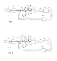
- the exemplary power plant arrangement 10 may include a main air compressor 12 for compressing ambient air into at least a first portion of a compressed ambient gas flow 26. Further, the exemplary power plant arrangement 10 may include a turbine combustor 32 that may be fluidly connected to the main air compressor 12. The turbine combustor 32 may be configured to receive the at least a first portion of the compressed ambient gas flow 26 from the main air compressor 12, at least a portion of a recirculated low oxygen content gas flow 50 from a turbine compressor 30, and a fuel stream 28, to form a combustible mixture and to burn the combustible mixture to generate the recirculated low oxygen content gas flow 50.
- the power plant arrangement 10 may include a turbine 34 located downstream of the turbine combustor 32.
- the turbine 34 may be configured to expand the recirculated low oxygen content gas flow 50 and may drive an external load such as a turbine generator 20 via a turbine shaft 22 to generate electricity.
- the main air compressor 12 and the turbine compressor 30 may be driven by the power generated by the turbine 34 via the turbine shaft 22.
- the term "recirculated low oxygen content gas flow” refers to the gas flow generated by the burning of the combustible mixture in the turbine combustor 32 and flowing through a recirculation loop 52.
- the term “low oxygen content” refers to an oxygen content of below about 5 vol%, below about 2 vol%, or below about 1 vol%.
- gas turbine assembly refers to all listed components of the power plant arrangements except for the main air compressor 12. In embodiments comprising multiple main air compressors, the term “gas turbine assembly” refers to all listed components of the power plant arrangements except for the multiple main air compressors.
- the gas turbine assembly may further comprise a secondary flow path 31 that may deliver at least a portion of the recirculated low oxygen content gas flow 50 from the turbine compressor 30 to the turbine 34 as a secondary flow.
- the secondary flow may be used to cool and seal the turbine 34, including individual components of the turbine 34 such as the turbine shroud, the turbine nozzle, the turbine blade tip, the turbine bearing support housing, and the like. After cooling and sealing the turbine 34 and any individual turbine components, the secondary flow may be directed into the recirculation loop 52 near the output of the turbine 34.
- the recirculated low oxygen content gas flow 50 may be directed from the turbine combustor 32 through the recirculation loop 52 to a heat recovery steam generator 36 for the generation of steam.
- a steam turbine may be further configured to generate additional electricity using the steam from the heat recovery steam generator 36, and the steam turbine may be connected to a steam generator.
- the steam turbine may be arranged to be connected to the turbine shaft 22.
- the recirculated low oxygen content gas flow 50 may then be directed back into the recirculation loop 52 to a recirculated gas flow cooler 40.
- the recirculation loop 52 may not contain a heat recovery steam generator 36 and the recirculated low oxygen content gas flow 50 may instead be introduced directly into the recirculated gas flow cooler 40 upon exit from the turbine 34. In still other embodiments, the recirculation loop 52 may not comprise the recirculated gas flow cooler 40.
- the recirculated gas flow cooler 40 may be incorporated into the recirculation loop 52 anywhere downstream of the turbine 34.
- the recirculated gas flow cooler 40 may be configured to lower the temperature of the recirculated low oxygen content gas flow 50 to a suitable temperature for downstream delivery into the turbine compressor 30 via the recirculation loop 52.
- a suitable temperature may be below about 66 °C, below about 49 °C, or below about 45 °C.
- the exemplary power plant arrangement 10 may include a recirculated gas flow extraction unit 46 located downstream of the turbine compressor 30 and may be fluid connection with at least a portion of the recirculated low oxygen content gas flow 50 via a turbine compressor output flow 44.
- the recirculated gas flow extraction unit 46 may be fluidly connected to a gas separation system via an extraction conduit 48.
- the gas separation system may produce at least a first process stream of concentrated carbon dioxide and a second process stream of concentrated nitrogen, both with a low oxygen content.
- the gas separation system may be, for instance, a carbon capture sequestration (CCS) system.
- CCS carbon capture sequestration
- the recirculated gas flow extraction unit 46 may be attached to any point of the recirculation loop 52.
- the turbine shaft 22 may be a "cold-end drive” configuration, meaning the turbine shaft 22 may connect to the turbine generator 20 at the compressor end of the turbine assembly.
- the turbine shaft 22 may be a "hot-end drive” configuration, meaning the turbine shaft 22 may connect to the turbine generator 20 at the turbine end of the turbine assembly.
- FIG. 2 is a diagrammatical illustration of an exemplary configuration 100 of the exemplary power plant arrangement 10 of FIG. 1 .
- a booster compressor 24 may be incorporated downstream of and in fluid connection with the main air compressor 12 and upstream of and in fluid connection with the turbine combustor 32.
- the booster compressor 24 may further compress the at least a first portion of the compressed ambient gas flow 26 before delivery into the turbine combustor 32.
- FIG. 3 is a diagrammatical illustration of an exemplary configuration 110 of the exemplary power plant arrangement 10 of FIG. 1 .
- a blower 42 may be fluidly connected to the recirculation loop 52 downstream of the recirculated gas flow cooler 40.
- the blower 42 may be configured to increase the pressure of the recirculated low oxygen content gas flow 50 prior to delivery into the turbine compressor 30 via the recirculation loop 52.
- FIG. 4 is a diagrammatical illustration of an exemplary configuration 120 of the exemplary power plant arrangement 10 of FIG. 1 .
- a booster compressor 24 may be incorporated downstream of and in fluid connection with the main air compressor 12 and upstream of and in fluid connection with the turbine combustor 32.
- the booster compressor 24 may further compress the at least a first portion of the compressed ambient gas flow 26 before delivery into the turbine combustor 32.
- a blower 42 may be fluidly connected to the recirculation loop 52 downstream of the recirculated gas flow cooler 40.
- the blower 42 may be configured to increase the pressure of the recirculated low oxygen content gas flow 50 prior to delivery into the turbine compressor 30 via the recirculation loop 52.
- FIG. 5 is a diagrammatical illustration of an exemplary configuration 130 of the exemplary power plant arrangement 10 of FIG. 1 .
- a blower 42 may be fluidly connected to the recirculation loop 52 upstream of the recirculated gas flow cooler 40.
- the blower 42 may be configured to increase the pressure of the recirculated low oxygen content gas flow 50 prior to delivery into the recirculated gas flow cooler 40 via the recirculation loop 52.
- FIG. 6 is a diagrammatical illustration of an exemplary configuration 140 of the exemplary power plant arrangement 10 of FIG. 1 .
- a booster compressor 24 may be incorporated downstream of and in fluid connection with the main air compressor 12 and upstream of and in fluid connection with the turbine combustor 32.
- the booster compressor 24 may further compress the at least a first portion of the compressed ambient gas flow 26 before delivery into the turbine combustor 32.
- a blower 42 may be fluidly connected to the recirculation loop 52 upstream of the recirculated gas flow cooler 40.
- the blower 42 may be configured to increase the pressure of the recirculated low oxygen content gas flow 50 prior to delivery into the recirculated gas flow cooler 40 via the recirculation loop 52.
- FIG. 7 is a diagrammatical illustration of an exemplary configuration 150 of the exemplary power plant arrangement 10 of FIG. 1 .
- the main air compressor 12 may not be driven by the power generated by the turbine 34 via the turbine shaft 22.
- the main air compressor 12 may not be connected to the turbine shaft 22.
- FIG. 8 is a diagrammatical illustration of an exemplary configuration 160 of the exemplary power plant arrangement 10 of FIG. 1 .
- the main air compressor 12 may not be driven by the power generated by the turbine 34 via the turbine shaft 22.
- the main air compressor 12 may not be connected to the turbine shaft 22.
- a booster compressor 24 may be incorporated downstream of and in fluid connection with the main air compressor 12 and upstream of and in fluid connection with the turbine combustor 32. The booster compressor 24 may further compress the at least a first portion of the compressed ambient gas flow 26 before delivery into the turbine combustor 32.
- FIG. 9 is a diagrammatical illustration of an exemplary configuration 170 of the exemplary power plant arrangement 10 of FIG. 1 .
- the main air compressor 12 may not be driven by the power generated by the turbine 34 via the turbine shaft 22.
- the main air compressor 12 may not be connected to the turbine shaft 22.
- a blower 42 may be fluidly connected to the recirculation loop 52 downstream of the recirculated gas flow cooler 40. The blower 42 may be configured to increase the pressure of the recirculated low oxygen content gas flow 50 prior to delivery into the turbine compressor 30 via the recirculation loop 52.
- FIG. 10 is a diagrammatical illustration of an exemplary configuration 180 of the exemplary power plant arrangement 10 of FIG. 1 .
- the main air compressor 12 may not be driven by the power generated by the turbine 34 via the turbine shaft 22.
- the main air compressor 12 may not be connected to the turbine shaft 22.
- a booster compressor 24 may be incorporated downstream of and in fluid connection with the main air compressor 12 and upstream of and in fluid connection with the turbine combustor 32. The booster compressor 24 may further compress the at least a first portion of the compressed ambient gas flow 26 before delivery into the turbine combustor 32.
- a blower 42 may be fluidly connected to the recirculation loop 52 downstream of the recirculated gas flow cooler 40.
- the blower 42 may be configured to increase the pressure of the recirculated low oxygen content gas flow 50 prior to delivery into the turbine compressor 30 via the recirculation loop 52.
- FIG. 11 is a diagrammatical illustration of an exemplary configuration 190 of the exemplary power plant arrangement 10 of FIG. 1 .
- the main air compressor 12 may not be driven by the power generated by the turbine 34 via the turbine shaft 22.
- the main air compressor 12 may not be connected to the turbine shaft 22.
- a blower 42 may be fluidly connected to the recirculation loop 52 upstream from the recirculated gas flow cooler 40. The blower 42 may be configured to increase the pressure of the recirculated low oxygen content gas flow 50 prior to delivery into the recirculated gas flow cooler 40 via the recirculation loop 52.
- FIG. 12 is a diagrammatical illustration of an exemplary configuration 200 of the exemplary power plant arrangement 10 of FIG. 1 .
- the main air compressor 12 may not be driven by the power generated by the turbine 34 via the turbine shaft 22.
- the main air compressor 12 may not be connected to the turbine shaft 22.
- a booster compressor 24 may be incorporated downstream of and in fluid connection with the main air compressor 12 and upstream of and in fluid connection with the turbine combustor 32. The booster compressor 24 may further compress the at least a first portion of the compressed ambient gas flow 26 before delivery into the turbine combustor 32.
- a blower 42 may be fluidly connected to the recirculation loop 52 upstream from the recirculated gas flow cooler 40.
- the blower 42 may be configured to increase the pressure of the recirculated low oxygen content gas flow 50 prior to delivery into the recirculated gas flow cooler 40 via the recirculation loop 52.
- slave is synonymous with the terms secondary, auxiliary, or additional.
- the term “slave” refers to the second of two gas turbine assemblies, but can also mean any additional gas turbine assemblies operated with a main gas turbine assembly such as is the second gas turbine assembly in the following embodiments.
- master train is synonymous with a first gas turbine assembly that may be mechanically connected to the main air compressor 12.
- slave train may also refer to the second of two or more gas turbine assemblies.
- FIG. 13 is a diagrammatical illustration of another exemplary power plant arrangement 300 in accordance with aspects of the present invention.
- the main air compressor 12 may deliver compressed ambient gas to a slave turbine combustor 72 that may be fluidly connected to the main air compressor 12 via an inter-train conduit 8.
- the slave turbine combustor 72 may be configured to receive the at least a second portion of the compressed ambient gas flow 66 from the main air compressor 12, at least a first portion of a slave recirculated low oxygen content gas flow 90 from a slave turbine compressor 70, and a slave fuel stream 68, to form a slave combustible mixture and to burn the slave combustible mixture to generate the slave recirculated low oxygen content gas flow 90.
- the exemplary power plant arrangement 300 may include a slave turbine 74 located downstream of the slave turbine combustor 72.
- the slave turbine 74 may be configured to expand the slave recirculated low oxygen content gas flow 90 and may drive an external load such as a slave turbine generator 60 via a slave turbine shaft 62 to generate electricity.
- slave recirculated low oxygen content gas flow refers to the gas flow generated by the burning of the slave combustible mixture in the slave turbine combustor 72 and flowing through a slave recirculation loop 92.
- low oxygen content refers to an oxygen content of below about 5 vol%, below about 2 vol%, or below about 1 vol%.
- the gas turbine assembly may further comprise a slave secondary flow path 71 that may deliver at least a portion of the slave recirculated low oxygen content gas flow 90 from the slave turbine compressor 70 to the slave turbine 74 as a slave secondary flow.
- the slave secondary flow may be used to cool and seal the slave turbine 74, including individual components of the slave turbine 74 such as the turbine shroud, the turbine nozzle, the turbine blade tip, the turbine bearing support housing, and the like. After cooling and sealing the slave turbine 74 and any individual turbine components, the slave secondary flow may be directed into the slave recirculation loop 92 near the output of the slave turbine 74.
- the slave recirculated low oxygen content gas flow 90 may be directed from the slave turbine combustor 72 through the slave recirculation loop 92 to a slave heat recovery steam generator 76 for the generation of steam.
- a slave steam turbine may be further configured to generate additional electricity using the steam from the slave heat recovery steam generator 76, and the slave steam turbine may be connected to a slave steam generator.
- the slave steam turbine may be arranged to be connected to the slave turbine shaft 62. The slave recirculated low oxygen content gas flow 90 may then be directed back into the slave recirculation loop 92 to a slave recirculated gas flow cooler 80.
- the recirculation loop 92 may not contain a slave heat recovery steam generator 76 and the slave recirculated low oxygen content gas flow 90 may instead be introduced directly into the slave recirculated gas flow cooler 80 upon exit from the slave turbine 74.
- the slave recirculation loop 92 may not comprise the slave recirculated gas flow cooler 80.
- the slave recirculated gas flow cooler 80 may be incorporated into the slave recirculation loop 92 anywhere downstream of the slave turbine 74.
- the slave recirculated gas flow cooler 80 may be configured to lower the temperature of the slave recirculated low oxygen content gas flow 90 to a suitable temperature for downstream delivery into the slave turbine compressor 70 via the slave recirculation loop 92.
- a suitable temperature may be below about 66 °C, below about 49 °C, or below about 45 °C.
- the exemplary power plant arrangement 300 may include a slave recirculated gas flow extraction unit 86 located downstream of the slave turbine compressor 70 and may be in fluid connection with at least a portion of the slave recirculated low oxygen content gas flow 90 via a slave turbine compressor output flow 84.
- the slave recirculated gas flow extraction unit 86 may be fluidly connected to a slave gas separation system via a slave extraction conduit 88.
- the slave gas separation system may produce at least a first slave process stream of concentrated carbon dioxide and a second slave process stream of concentrated nitrogen, both with a low oxygen content.
- the slave gas separation system may be, for instance, a slave carbon capture sequestration (CCS) system.
- the slave recirculated gas flow extraction unit 86 may be attached to any point of the slave recirculation loop 92.
- the slave turbine shaft 62 may be a "cold-end drive” configuration, meaning the slave turbine shaft 62 may connect to the slave turbine generator 60 at the compressor end of the turbine assembly.
- the slave turbine shaft 62 may be a "hot-end drive” configuration, meaning the slave turbine shaft 62 may connect to the slave turbine generator 60 at the turbine end of the turbine assembly.
- the turbine shaft 22 may be a "cold-end drive” configuration, meaning the turbine shaft 22 may connect to the turbine generator 20 at the compressor end of the turbine assembly.
- the turbine shaft 22 may be a "hot-end drive” configuration, meaning the turbine shaft 22 may connect to the turbine generator 20 at the turbine end of the turbine assembly.
- FIG. 14 is a diagrammatical illustration of an exemplary configuration 310 of the exemplary power plant arrangement 300 of FIG. 13 .
- a booster compressor 24 may be incorporated downstream of and in fluid connection with the main air compressor 12 and upstream of and in fluid connection with the turbine combustor 32.
- the booster compressor 24 may further compress the at least a first portion of the compressed ambient gas flow 26 before delivery into the turbine combustor 32.
- a slave booster compressor 64 may be incorporated downstream of and in fluid connection with the main air compressor 12 and upstream of and in fluid connection with the slave turbine combustor 72.
- the slave booster compressor 64 may further compress the at least a second portion of the compressed ambient gas flow 66 before delivery into the slave turbine combustor 72.
- FIG. 15 is a diagrammatical illustration of an exemplary configuration 320 of the exemplary power plant arrangement 300 of FIG. 13 .
- a blower 42 may be fluidly connected to the recirculation loop 52 downstream from the recirculated gas flow cooler 40.
- the blower 42 may be configured to increase the pressure of the recirculated low oxygen content gas flow 50 prior to delivery into the turbine compressor 30 via the recirculation loop 52.
- a slave blower 82 may be fluidly connected to the slave recirculation loop 92 downstream of the slave recirculated gas flow cooler 80.
- the slave blower 82 may be configured to increase the pressure of the slave recirculated low oxygen content gas flow 90 prior to delivery into the slave turbine compressor 70 via the slave recirculation loop 92.
- FIG. 16 is a diagrammatical illustration of an exemplary configuration 330 of the exemplary power plant arrangement 300 of FIG. 13 .
- a booster compressor 24 may be incorporated downstream of and in fluid connection with the main air compressor 12 and upstream of and in fluid connection with the turbine combustor 32.
- the booster compressor 24 may further compress the at least a first portion of the compressed ambient gas flow 26 before delivery into the turbine combustor 32.
- a blower 42 may be fluidly connected to the recirculation loop 52 downstream of the recirculated gas flow cooler 40.
- the blower 42 may be configured to increase the pressure of the recirculated low oxygen content gas flow 50 prior to delivery into the turbine compressor 30 via the recirculation loop 52.
- a slave booster compressor 64 may be incorporated downstream of and in fluid connection with the main air compressor 12 and upstream of and in fluid connection with the slave turbine combustor 72.
- the slave booster compressor 64 may further compress the at least a second portion of the compressed ambient gas flow 66 before delivery into the slave turbine combustor 72.
- a slave blower 82 may be fluidly connected to the slave recirculation loop 92 downstream of the slave recirculated gas flow cooler 80.
- the slave blower 82 may be configured to increase the pressure of the slave recirculated low oxygen content gas flow 90 prior to delivery into the slave turbine compressor 70 via the slave recirculation loop 92.
- FIG. 17 is a diagrammatical illustration of an exemplary configuration 340 of the exemplary power plant arrangement 300 of FIG. 13 .
- a blower 42 may be fluidly connected to the recirculation loop 52 upstream of the recirculated gas flow cooler 40.
- the blower 42 may be configured to increase the pressure of the recirculated low oxygen content gas flow 50 prior to delivery into the recirculated gas flow cooler 40 via the recirculation loop 52.
- a slave blower 82 may be fluidly connected to the slave recirculation loop 92 upstream of the slave recirculated gas flow cooler 80.
- the slave blower 82 may be configured to increase the pressure of the slave recirculated low oxygen content gas flow 90 prior to delivery into the slave recirculated gas flow cooler 80 via the slave recirculation loop 92.
- FIG. 18 is a diagrammatical illustration of an exemplary configuration 350 of the exemplary power plant arrangement 300 of FIG. 13 .
- a booster compressor 24 may be incorporated downstream of and in fluid connection with the main air compressor 12 and upstream of and in fluid connection with the turbine combustor 32.
- the booster compressor 24 may further compress the at least a first portion of the compressed ambient gas flow 26 before delivery into the turbine combustor 32.
- a blower 42 may be fluidly connected to the recirculation loop 52 upstream of the recirculated gas flow cooler 40.
- the blower 42 may be configured to increase the pressure of the recirculated low oxygen content gas flow 50 prior to delivery into the recirculated gas flow cooler 40 via the recirculation loop 52.
- a slave booster compressor 64 may be incorporated downstream of and in fluid connection with the main air compressor 12 and upstream of and in fluid connection with the slave turbine combustor 72.
- the slave booster compressor 64 may further compress the at least a second portion of the compressed ambient gas flow 66 before delivery into the slave turbine combustor 72.
- a slave blower 82 may be fluidly connected to the slave recirculation loop 92 upstream of the slave recirculated gas flow cooler 80.
- the slave blower 82 may be configured to increase the pressure of the slave recirculated low oxygen content gas flow 90 prior to delivery into the slave recirculated gas flow cooler 80 via the slave recirculation loop 92.
- FIG. 19 is a diagrammatical illustration of an exemplary configuration 360 of the exemplary power plant arrangement 300 of FIG. 13 .
- the main air compressor 12 may not be driven by the power generated by the turbine 34 via the turbine shaft 22.
- the main air compressor 12 may not be connected to the turbine shaft 22.
- FIG. 20 is a diagrammatical illustration of an exemplary configuration 370 of the exemplary power plant arrangement 300 of FIG. 14 .
- the main air compressor 12 may not driven by the power generated by the turbine 34 via the turbine shaft 22.
- the main air compressor 12 may not be connected to the turbine shaft 22.
- a booster compressor 24 may be incorporated downstream of and in fluid connection with the main air compressor 12 and upstream of and in fluid connection with the turbine combustor 32. The booster compressor 24 may further compress the at least a first portion of the compressed ambient gas flow 26 before delivery into the turbine combustor 32.
- a slave booster compressor 64 may be incorporated downstream of and in fluid connection with the main air compressor 12 and upstream of and in fluid connection with the slave turbine combustor 72.
- the slave booster compressor 64 may further compress the at least a second portion of the compressed ambient gas flow 66 before delivery into the slave turbine combustor 72.
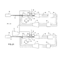
- FIG. 21 is a diagrammatical illustration of an exemplary configuration 380 of the exemplary power plant arrangement 300 of FIG. 14 .
- the main air compressor 12 may not be driven by the power generated by the turbine 34 via the turbine shaft 22.
- the main air compressor 12 may not be connected to the turbine shaft 22.
- a blower 42 may be fluidly connected to the recirculation loop 52 downstream of the recirculated gas flow cooler 40. The blower 42 may be configured to increase the pressure of the recirculated low oxygen content gas flow 50 prior to delivery into the turbine compressor 30 via the recirculation loop 52.
- a slave blower 82 may be fluidly connected to the slave recirculation loop 92 downstream of the slave recirculated gas flow cooler 80.
- the slave blower 82 may be configured to increase the pressure of the slave recirculated low oxygen content gas flow 90 prior to delivery into the slave turbine compressor 70 via the slave recirculation loop 92.
- FIG. 22 is a diagrammatical illustration of an exemplary configuration 390 of the exemplary power plant arrangement 300 of FIG. 14 .
- the main air compressor 12 may not be driven by the power generated by the turbine 34 via the turbine shaft 22.
- the main air compressor 12 may not be connected to the turbine shaft 22.
- a booster compressor 24 may be incorporated downstream of and in fluid connection with the main air compressor 12 and upstream of and in fluid connection with the turbine combustor 32. The booster compressor 24 may further compress the at least a first portion of the compressed ambient gas flow 26 before delivery into the turbine combustor 32.
- a blower 42 may be fluidly connected to the recirculation loop 52 downstream of the recirculated gas flow cooler 40.
- the blower 42 may be configured to increase the pressure of the recirculated low oxygen content gas flow 50 prior to delivery into the turbine compressor 30 via the recirculation loop 52.
- a slave booster compressor 64 may be incorporated downstream of and in fluid connection with the main air compressor 12 and upstream of and in fluid connection with the slave turbine combustor 72.
- the slave booster compressor 64 may further compress the at least a second portion of the compressed ambient gas flow 66 before delivery into the slave turbine combustor 72.
- a slave blower 82 may be fluidly connected to the slave recirculation loop 92 downstream of the slave recirculated gas flow cooler 80.
- the slave blower 82 may be configured to increase the pressure of the slave recirculated low oxygen content gas flow 90 prior to delivery into the slave turbine compressor 70 via the slave recirculation loop 92.
- FIG. 23 is a diagrammatical illustration of an exemplary configuration 400 of the exemplary power plant arrangement 300 of FIG. 13 .
- the main air compressor 12 may not be driven by the power generated by the turbine 34 via the turbine shaft 22.
- the main air compressor 12 may not be connected to the turbine shaft 22.
- a blower 42 may be fluidly connected to the recirculation loop 52 upstream from the recirculated gas flow cooler 40. The blower 42 may be configured to increase the pressure of the recirculated low oxygen content gas flow 50 prior to delivery into the recirculated gas flow cooler 40 via the recirculation loop 52.
- a slave blower 82 may be fluidly connected to the slave recirculation loop 92 upstream of the slave recirculated gas flow cooler 80.
- the slave blower 82 may be configured to increase the pressure of the slave recirculated low oxygen content gas flow 90 prior to delivery into the slave recirculated gas flow cooler 80 via the slave recirculation loop 92.
- FIG. 24 is a diagrammatical illustration of an exemplary configuration 410 of the exemplary power plant arrangement 300 of FIG. 13 .
- the main air compressor 12 may not be driven by the power generated by the turbine 34 via the turbine shaft 22.
- the main air compressor 12 may not connected to the turbine shaft 22.
- a booster compressor 24 may be incorporated downstream of and in fluid connection with the main air compressor 12 and upstream of and in fluid connection with the turbine combustor 32. The booster compressor 24 may further compress the at least a first portion of the compressed ambient gas flow 26 before delivery into the turbine combustor 32.
- a blower 42 may be fluidly connected to the recirculation loop 52 upstream of the recirculated gas flow cooler 40.
- the blower 42 may be configured to increase the pressure of the recirculated low oxygen content gas flow 50 prior to delivery into the recirculated gas flow cooler 40 via the recirculation loop 52.
- a slave booster compressor 64 may be incorporated downstream of and in fluid connection with the main air compressor 12 and upstream of and in fluid connection with the slave turbine combustor 72.
- the slave booster compressor 64 may further compress the at least a second portion of the compressed ambient gas flow 66 before delivery into the slave turbine combustor 72.
- a slave blower 82 may be fluidly connected to the slave recirculation loop 92 upstream of the slave recirculated gas flow cooler 80.
- the slave blower 82 may be configured to increase the pressure of the slave recirculated low oxygen content gas flow 90 prior to delivery into the slave recirculated gas flow cooler 80 via the slave recirculation loop 92.
- the power plant arrangement may comprise one gas turbine assembly. In other embodiments, the power plant arrangement may comprise two or more gas turbine assemblies that are fluidly connected by the inter-train conduit 8. As used herein, the term "inter-train conduit" may refer to any fluid connection between two or more gas turbine assemblies and one or more main air compressors. In still other embodiments, the power plant arrangement may comprise three or more gas turbine assemblies and one or more additional main air compressors, wherein the additional main air compressors are in fluid connection with each other and with the gas turbine assemblies. In yet other embodiments, the power plant arrangement may be configured for substantially stoichiometric combustion. In still other embodiments, the power plant arrangement may be configured for substantially zero emissions power production.
- the fuel stream 28 and/or the slave fuel stream 68 may comprise an organic gas, including but not limited to methane, propane, and/or butane. In still other embodiments, the fuel stream 28 and/or the slave fuel stream 68 may comprise an organic liquid, including but not limited to methanol and/or ethanol. In yet other embodiments, the fuel stream 28 and/or the slave fuel stream 68 may comprise a fuel source obtained from a solid carbonaceous material such as coal.
- the term "master train” refers to any gas turbine assembly that also includes a main air compressor.
- the term “slave train” refers to any gas turbine assembly that does not also include a main air compressor. Thus, any given slave train requires at least one master train for operation.
- a power plant arrangement may comprise only a master train. In such a situation, the master train may be started using the protocol described below for master train start-up.
- Ambient air may be compressed into a compressed ambient gas flow using a main air compressor 12.
- An air injection valve 15 may be opened to allow the delivery of the compressed ambient gas flow into an inter-train conduit 8.
- a master air injection valve 25, fluidly connecting the inter-train conduit 8 to a master turbine combustor 32, may also be opened.
- At least a first portion of the compressed ambient gas flow 26, having a compressed ambient gas flow rate, may be delivered to a master turbine combustor 32 that is fluidly connected to the main air compressor 12.
- a master turbine bypass valve 47 connected to a master bypass conduit 49 may be opened.
- the master bypass conduit 49 may be fluidly connected to an output of a master turbine compressor 30 and may be configured to deliver a master bypass flow to a master recirculation loop 52 at a location that is downstream of a master turbine 34.
- a master exhaust port such as a master damper door 38, that may be fluidly connected to the master recirculation loop 52 may be opened such that the master recirculation loop 52 may be vented to the atmosphere.
- the master exhaust port may be fluidly connected to the master recirculation loop 52.
- the master exhaust port may be fluidly connected to the master bypass conduit 49.
- the master exhaust port may be fluidly connected to the master extraction conduit 48.
- the master exhaust port may vent the master train to the atmosphere. In other embodiments, the master exhaust port may not vent the master train to the atmosphere.
- the master train of the exemplary power plant arrangement 420 may be purged just before ignition in order to vent any combustibles that may have accumulated in the master train prior to ignition.
- the master extraction valve 45 and the master gas control valve 27 must be closed, while the master air injection valve 25 must be opened for purge.
- a master turbine shaft 22 connected to the master turbine 34 and to the master turbine compressor 30 may be rotated at a purge speed. The rotation of the master turbine shaft 22 might be accomplished with, for instance, a master turbine generator 20 or a starting motor.
- the master turbine generator 20 may be equipped with a load-commutated inverter to supply rotational power to the master turbine shaft 22.
- the master turbine shaft 22 may be operated at a purge speed, which may be in the range of about 20% to about 30% of the maximum turbine rotation speed. In other embodiments, the purge speed may be in the range of about 22% to about 28% of the maximum turbine rotation speed. In still other embodiments, the purge speed may be about 25% of the maximum turbine rotation speed.
- the exemplary power plant arrangement 420 may be operated under purge conditions until all volatile combustibles have been vented from the master train.
- the inlet guide vanes of the main air compressor 12 may be adjusted to control the master purge air flow. Additionally, during the purge step the variable bleed valve 14 may be used to vent any additional air pressure generated by the main air compressor 12, as necessary, to prevent over-pressurization of the master gas turbine assembly.
- the step of purging may include the use of the master booster compressor 24 which may be incorporated downstream of and in fluid connection with the main air compressor 12 and upstream of and in fluid connection with the master turbine combustor 32.
- the master booster compressor 24 may further compress the at least a first portion of the compressed ambient gas flow 26 before delivery into the master turbine combustor 32.
- the exhaust of the master booster combustor 24 may be delivered to the master turbine combustor 32.
- the exhaust of the master booster compressor 24 may be regulated by the master air injection valve 25.
- the step of purging may include the use of the master turbine blower 42 that is located in the master recirculation loop 52.
- the purge step is not necessary.
- the master train of the exemplary power plant arrangement 420 has already been purged, for instance during a previous shutdown.
- the next step is ignition of the master train in the exemplary power plant arrangement 420.
- the master turbine shaft 22 connected to the master turbine 34 and to the master turbine compressor 30 may be rotated at the purge speed or at an ignition speed.
- the rotation of the master turbine shaft 22 might be accomplished with, for instance, a master turbine generator 20 or a starting motor.
- the master turbine generator 20 may be equipped with a load-commutated inverter to supply rotational power to the master turbine shaft 22.
- the ignition speed may be in the range of about 10% to about 20% of the maximum turbine rotation speed. In other embodiments, the ignition speed may be in the range of about 12% to about 16% of the maximum turbine rotation speed. In still other embodiments, the ignition speed may be about 14% of the maximum turbine rotation speed.
- a master fuel stream 28, having a master fuel stream flow rate, may be delivered to the master turbine combustor 32 for mixing with the at least a first portion of the compressed ambient gas flow 26 to form a master combustible mixture.
- Spark plugs in the master turbine combustor 32 may be ignited and the master combustible mixture may be burned in the master turbine combustor 32 and thereby form the master recirculated gas flow 50 and drive the master turbine 34 connected to the master turbine compressor 30 via the master turbine shaft 22.
- driving means that both the master turbine 34 and the master turbine compressor 30 rotate.
- the master booster compressor 24 may be adjusted during ignition as necessary.
- the master recirculated gas flow 50 may then be recirculated from the master turbine 34 to the master turbine compressor 30 using the master recirculation loop 52.
- the master recirculation loop 52 may fluidly connect an output of the master turbine 34 with an input of the master turbine compressor 30.
- the master recirculated gas flow 50 may further pass through the master heat recovery steam generator 36, the master recirculated gas flow cooler 40, and the master turbine blower 42 en route from the output of the master turbine 34 to the input of master turbine compressor 30.
- the master train may further comprise a master secondary flow path 31 that may deliver at least a portion of the master recirculated gas flow 50 from the master turbine compressor 30 to the master turbine 34 as a master secondary flow.
- the master secondary flow may be used to cool and to seal the master turbine 34, including individual components of the master turbine 34 such as the turbine shroud, the turbine nozzle, the turbine blade tip, the turbine bearing support housing, and the like. After cooling and sealing the master turbine 34 and any individual master turbine components, the master secondary flow may be directed into the master recirculation loop 52 near the output of the master turbine 34.
- the master secondary flow path 31 may be used throughout the entire start-up method.
- the next step is operating the master turbine 34 at a master target operating speed.
- the master target operating speed may be about 3000 rpm for a 50 Hz grid or about 3600 rpm for a 60 Hz grid.
- the master target operating speed may match the required speed of auxiliary apparatus for which the master turbine 34 is driving.
- the master turbine 34 may be operating at a master target operating speed after ignition. In other embodiments, the master turbine 34 may need to be accelerated to a master target operating speed after ignition. In some embodiments, the master turbine 34 may be accelerated to a master target operating speed by adjusting the master fuel stream flow rate and the master compressed ambient gas flow rate.
- the load-commutated inverter may be used to accelerate the master turbine shaft 22 until the burning of the master combustible mixture provides a master turbine power that is enough to sustain the power needs of the master turbine compressor 30 and/or the main air compressor 12.
- the inverter may be disengaged before or during acceleration of the master turbine 34.
- the master turbine 34 may be driven by the master recirculated gas flow 50 generated by combustion in the master turbine combustor 32.
- the step of acceleration may comprise adjusting the master fuel stream flow rate by adjusting the master gas control valve 27.
- the step of acceleration may comprise adjusting the inlet guide vanes of the main air compressor 12.
- the step of acceleration may comprise adjusting the master booster compressor 24.
- the master variable bleed valve 14 may be closed to facilitate acceleration.
- the master recirculated gas flow 50 expands in the master turbine 34, thereby causing the master turbine 34 to rotate.
- the term "driven using the master recirculated gas flow” means the master recirculated gas flow 50 expands upon exit from the master turbine combustor 32 and upon entrance into the master turbine 34, thereby causing the master turbine 34 to rotate.
- rotation of the master turbine 34 causes the master turbine shaft 22 and the master turbine compressor 30 to also rotate.
- the next step may be synchronizing the master train to the power grid.
- the master turbine generator 20 may be synchronized to a power grid and the master turbine generator 20 may then be electrically connected to the power grid.
- "synchronized to a power grid” means synchronizing the three phases of the alternating current of the master turbine generator 20 to the three phases of the alternating current of the power grid.
- the master turbine shaft 22 may be connected to the master turbine generator 20, such that rotation of the master turbine shaft 22 may cause the master turbine generator 20 to generate electricity once the master turbine generator circuit breaker is closed.
- a master circuit breaker connecting the master turbine generator 20 to the power grid may be closed once the master turbine generator 20 is synchronized to the power grid.
- the master train may then be loaded to a desired load point.
- loaded means that the rotation of the master turbine shaft 22 in the master turbine generator 20 is converted from mechanical energy to electrical energy, wherein the electrical energy is transferred to the power grid.
- the turbine shaft 22 may not be connected to a turbine generator 20. In some embodiments, the turbine shaft 22 may instead be used as a mechanical drive for auxiliary apparatus.
- the master fuel stream flow rate and the master compressed ambient gas flow rate may be adjusted as necessary.
- the master booster compressor 24 may be adjusted during loading as necessary.
- the master recirculated gas flow 50 may be directed through the master heat recovery steam generator 36 for the generation of steam.
- a master steam turbine may be further configured to generate additional electricity using the steam from the master heat recovery steam generator 36, and the master steam turbine may be connected to a master steam generator.
- the master heat recovery steam generator 36 in conjunction with the master steam turbine and the master steam generator, may be configured to generate additional electricity when the temperature of the master recirculated gas flow 50 is in the range from about 200 °C to about 700 °C, from about 260 °C to about 600 °C, or from about 300 °C to about 550 °C.
- the master steam turbine may be connected to the master turbine shaft 22.
- the next step may be reaching substantially stoichiometric combustion in the master train.
- the step of reaching substantially stoichiometric combustion may also be performed prior to loading.
- the step comprises adjusting the master fuel stream flow rate and the master compressed ambient gas flow rate to reach substantial combustion stoichiometry.
- substantial combustion stoichiometry means that the oxygen content after the combustion reaction may be below about 5 vol%, below about 2 vol%, or below about 1 vol%.
- the master fuel stream flow rate of the master fuel stream 28 to the master turbine combustor 32 may be regulated by a master gas control valve 27 an effective amount to achieve substantially stoichiometric combustion.
- the master compressed ambient gas flow rate of the at least a first portion of the compressed ambient gas flow 26 from the main air compressor 12 to the master turbine combustor 32 may be adjusted using the inlet guide vanes of the main air compressor 12.
- the master booster compressor 24 may be adjusted as necessary.
- the air supply valve 15 may be adjusted as necessary. Additionally, in some embodiments, the master air injection valve 25 may be adjusted.
- the next step may be extracting a low-oxygen stream from the master train of the exemplary power plant arrangement 420.
- a master exhaust port such as the master damper door 38, may be closed.
- the master turbine bypass valve 47 may be closed.
- At least a portion of the master recirculated gas flow 50 may be extracted using a master extraction conduit 48 that is fluidly connected to the output of the master turbine compressor 30.
- a master extraction valve 45 which fluidly connects the master extraction conduit 48 to a master gas separation system, may further be opened.
- the master extraction conduit 48 which may be regulated by a master extraction valve 45.
- the master extraction valve 45 may be fluidly connected to the master bypass conduit 49 at a point that is either upstream of or downstream of the master turbine bypass valve 47.
- the master extraction conduit 48 may be fluidly connected to a master gas separation system 46 such as a carbon capture sequestration (CCS) system.
- CCS carbon capture sequestration
- the master gas separation system 46 may produce a stream of concentrated carbon dioxide and concentrated nitrogen, both with a low oxygen content.
- the master booster compressor 24 may be adjusted as necessary.
- one or more master trains in addition to starting one or more master trains, it may be desirable to also start one or more slave trains. It should be noted, however, that one or more master trains may be started without starting any slave trains. However, no slave trains may be started until at least one master train has been started.
- a method for starting-up the slave train of a stoichiometric exhaust gas recirculation power plant arrangement 420 is provided.
- Ambient air may be compressed into a compressed ambient gas flow using a main air compressor 12.
- the inter-train valve 16 may be opened and the slave variable bleed valve 18 may be closed.
- a slave air injection valve 65 fluidly connecting the inter-train conduit 8 to a slave turbine combustor 72, may be opened.
- At least a second portion of the compressed ambient gas flow 66, having a slave compressed ambient gas flow rate, may be delivered to a slave turbine combustor 72 that is fluidly connected to the main air compressor 12.
- a slave turbine bypass valve 87 connected to a slave bypass conduit 89 may be opened.
- the slave bypass conduit 89 may be fluidly connected to an output of a slave turbine compressor 70 and may be configured to deliver a slave bypass flow to a slave recirculation loop 92 at a location that is downstream of a slave turbine 74.
- a slave exhaust port such as a slave damper door 78, that may be fluidly connected to the slave recirculation loop 92, may be opened such that the slave recirculation loop 92 may be vented to the atmosphere.
- the slave exhaust port may be fluidly connected to the slave recirculation loop 92.
- the slave exhaust port may be fluidly connected to the slave bypass conduit 89.
- the slave exhaust port may be fluidly connected to the slave extraction conduit 88.
- the slave exhaust port may vent the slave train to the atmosphere. In other embodiments, the slave exhaust port may not vent the slave train to the atmosphere.
- the slave train of the exemplary power plant arrangement 420 may be purged just before ignition in order to vent any combustibles that may have accumulated in the slave train prior to ignition.
- the slave extraction valve 85 and the slave gas control valve 67 must be closed, while the slave air injection valve 65 must be opened for purge.
- a slave turbine shaft 62 connected to the slave turbine 74 and to the slave turbine compressor 70 may be rotated at a purge speed. The rotation of the slave turbine shaft 62 might be accomplished with, for instance, a slave turbine generator 60 or a starting motor.
- the slave turbine generator 60 may be equipped with a load-commutated inverter to supply rotational power to the slave turbine shaft 62.
- the slave turbine shaft 62 may be operated at a purge speed, which may be in the range of about 20% to about 30% of the maximum turbine rotation speed. In other embodiments, the purge speed may be in the range of about 22% to about 28% of the maximum turbine rotation speed. In still other embodiments, the purge speed may be about 25% of the maximum turbine rotation speed.
- the slave train of the exemplary power plant arrangement 100 may be operated under purge conditions until all volatile combustibles have been vented from the slave train.
- the slave air injection valve 65 may be adjusted to control the purge air flow.
- the step of purging may include the use of the slave booster compressor 64 which may be incorporated downstream of and in fluid connection with the main air compressor 12 and upstream of and in fluid connection with the slave turbine combustor 72.
- the slave booster compressor 64 may further compress the at least a second portion of the compressed ambient gas flow 66 before delivery into the slave turbine combustor 72.
- the exhaust of the slave booster compressor 64 may be delivered to the slave turbine combustor 72.
- the exhaust of the slave booster compressor 64 may be regulated by the slave air injection valve 65.
- the step of purging may include the use of the slave turbine blower 82 that is located in the slave recirculation loop 92.
- the purge step is not necessary.
- the slave train of the exemplary power plant arrangement 420 has already been purged, for instance during a previous shutdown.
- the next step is ignition of the slave train in the exemplary power plant arrangement 420.
- the slave turbine shaft 62 connected to the slave turbine 74 and to the slave turbine compressor 70 may be rotated at the purge speed or at an ignition speed.
- the rotation of the slave turbine shaft 62 might be accomplished with, for instance, a slave turbine generator 60 or a starting motor.
- the slave turbine generator 60 may be equipped with a load-commutated inverter to supply rotational power to the slave turbine shaft 62.
- the ignition speed may be in the range of about 10% to about 20% of the maximum turbine rotation speed. In other embodiments, the ignition speed may be in the range of about 12% to about 16% of the maximum turbine rotation speed. In still other embodiments, the ignition speed may be about 14% of the maximum turbine rotation speed.
- a slave fuel stream 68 having a slave fuel stream flow rate, may be delivered to the slave turbine combustor 72 for mixing with the at least a second portion of the compressed ambient gas flow 66 to form a slave combustible mixture.
- Spark plugs in the slave turbine combustor 72 may be ignited and the slave combustible mixture may be burned in the slave turbine combustor 72 and thereby form the slave recirculated gas flow 90 and drive the slave turbine 74 connected to the slave turbine compressor 70 via the slave turbine shaft 62.
- driving means that both the slave turbine 74 and the slave turbine compressor 70 rotate.
- the slave booster compressor 64 may be adjusted as necessary.
- the slave recirculated gas flow 90 may then be recirculated from the slave turbine 74 to the slave turbine compressor 70 using the slave recirculation loop 92.
- the slave recirculation loop 92 may fluidly connect an output of the slave turbine 74 with an input of the slave turbine compressor 70.
- the slave recirculated gas flow 90 may further pass through the slave heat recovery steam generator 76, the slave recirculated gas flow cooler 80, and the slave turbine blower 82 en route from the output of the slave turbine 74 to the input of slave turbine compressor 70.
- the slave train may further comprise a slave secondary flow path 71 that may deliver at least a portion of the slave recirculated gas flow 90 from the slave turbine compressor 70 to the slave turbine 74 as a slave secondary flow.
- the slave secondary flow may be used to cool and to seal the slave turbine 74, including individual components of the slave turbine 74 such as the turbine shroud, the turbine nozzle, the turbine blade tip, the turbine bearing support housing, and the like. After cooling and sealing the slave turbine 74 and any individual slave turbine components, the slave secondary flow may be directed into the slave recirculation loop 92 near the output of the slave turbine 74.
- the slave secondary flow path 71 may be used throughout the entire start-up method.
- the next step is operating the slave turbine 74 at a slave target operating speed.
- the target operating speed may be about 3000 rpm for a 50 Hz grid or about 3600 rpm for a 60 Hz grid.
- the slave target operating speed may match the required speed of auxiliary apparatus for which the slave turbine 74 is driving.
- the master target operating speed and the slave target operating speed are the same. In other embodiments, the master target operating speed and the slave target operating speed are not the same.
- the slave turbine 74 may be operating at a slave target operating speed after ignition. In other embodiments, the slave turbine 74 may need to be accelerated to a slave target operating speed after ignition. In some embodiments, the slave turbine 74 may be accelerated to a slave target operating speed by adjusting the slave fuel stream flow rate and the slave compressed ambient gas flow rate.
- the load-commutated inverter may be used to accelerate the slave turbine shaft 62 until the burning of the slave combustible mixture provides a slave turbine power that is enough to sustain the power needs of the slave turbine compressor 70.
- the inverter may be disengaged before or during acceleration of the slave turbine 74.
- the slave turbine 74 may be driven by the slave recirculated gas flow 90 generated by combustion in the slave turbine combustor 72.
- the step of acceleration may comprise adjusting the slave fuel stream flow rate by adjusting the slave gas control valve 67.
- the step of acceleration may comprise adjusting the slave booster compressor 64.
- the slave variable bleed valve 18 may be closed to facilitate acceleration.
- the air supply valve 15 may be adjusted during acceleration as necessary.
- the slave recirculated gas flow 90 may expand in the slave turbine 74, thereby causing the slave turbine 74 to rotate.
- the term "driven using the slave recirculated gas flow” means the slave recirculated gas flow 90 expands upon exit from the slave turbine combustor 72 and upon entrance into the slave turbine 74, thereby causing the slave turbine 74 to rotate.
- rotation of the slave turbine 74 causes the slave turbine shaft 62 and the slave turbine compressor 70 to also rotate.
- the next step may be synchronizing the slave train to the power grid.
- the slave turbine generator 60 may be synchronized to a power grid and the slave turbine generator 60 may then be electrically connected to the power grid.
- "synchronized to a power grid” means synchronizing the three phases of the alternating current of the slave turbine generator 60 to the three phases of the alternating current of the power grid.
- the slave turbine shaft 62 may be connected to the slave turbine generator 60, such that rotation of the slave turbine shaft 62 may cause the slave turbine generator 60 to generate electricity once the slave turbine generator circuit breaker is closed.
- a slave circuit breaker connecting the slave turbine generator 60 to the power grid may be closed once the slave turbine generator 60 is synchronized to the power grid.
- the slave train may then be loaded to a desired load point.
- loaded means that the rotation of the slave turbine shaft 62 in the slave turbine generator 60 is converted from mechanical energy to electrical energy, wherein the electrical energy is transferred to the power grid.
- the slave fuel stream flow rate and the slave compressed ambient gas flow rate may be adjusted as necessary.
- the slave booster compressor 64 may be adjusted as necessary.
- the slave recirculated gas flow 90 may be directed through the slave heat recovery steam generator 76 for the generation of steam.
- a slave steam turbine may be further configured to generate additional electricity using the steam from the slave heat recovery steam generator 76, and the slave steam turbine may be connected to a slave steam generator.
- the slave heat recovery steam generator 76 in conjunction with the slave steam turbine and slave steam generator, may be configured to generate additional electricity, in conjunction with the slave steam turbine and the slave steam generator, when the temperature of the slave recirculated gas flow 90 is in the range from about 200 °C to about 700 °C, from about 260 °C to about 600 °C, or from about 300 °C to about 550 °C.
- the slave steam turbine may be connected to the slave turbine shaft 62.
- the next step may be reaching substantially stoichiometric combustion in the slave train.
- the step of reaching substantially stoichiometric combustion may also be performed prior to loading.
- the step comprises adjusting the slave fuel stream flow rate and the slave compressed ambient gas flow rate to reach substantial combustion stoichiometry.
- substantial combustion stoichiometry means that the oxygen content after the combustion reaction may be below about 5 vol%, below about 2 vol%, or below about 1 vol%.
- the slave fuel stream flow rate of the slave fuel stream 68 to the slave turbine combustor 72 may be regulated by a slave gas control valve 67 an effective amount to achieve substantially stoichiometric combustion.
- the slave compressed ambient gas flow rate of the at least a second portion of the compressed ambient gas flow 66 from the main air compressor 12 to the slave turbine combustor 32 may be adjusted using the slave air injection valve 65.
- the slave booster compressor 64 may be adjusted as necessary.
- the next step may be extracting a low-oxygen content gas stream from the slave train of the exemplary power plant arrangement 420.
- a slave exhaust port such as the slave damper door 78, may be closed. Additionally, the slave turbine bypass valve 87 may be closed. At least a portion of the slave recirculated gas flow 90 may be extracted using a slave extraction conduit 88 that is fluidly connected to the output of the slave turbine compressor 70.
- a slave extraction valve 85 which fluidly connects the slave extraction conduit 88 to a slave gas separation system, may further be opened.
- a portion of the slave recirculated gas flow 90 from the output of the slave turbine compressor 70 may be extracted through the slave extraction conduit 88 which may be regulated by a slave extraction valve 85.
- the slave extraction valve 85 may be fluidly connected to the slave bypass conduit 89 at a point that is either upstream of or downstream of the slave turbine bypass valve 87.
- the slave extraction conduit 88 may be fluidly connected to a slave gas separation system such as a carbon capture sequestration (CCS) system.
- CCS carbon capture sequestration
- the slave gas separation system may produce a stream of concentrated carbon dioxide and concentrated nitrogen, both with a low oxygen content.
- the slave booster compressor 64 may be adjusted as necessary.
- each train will have a purge status. If a train has previously been purged, then no purge is needed. If, however, one or more trains have not been previously purged, then purging will be needed. For purging, all unpurged trains may be purged at once, each train may be purged prior to individual starting, or unpurged trains may be purged in waves, as needed.
- a method for operating the exemplary power plant arrangement 420 wherein the inter-train valve 16 may be open. It should be noted that operation of only the master train would comprise the same steps, except the inter-train valve 16 would be closed and steps referring to the slave train would be omitted. Similarly, a power plant arrangement comprising only a master train would follow these same steps, except that steps referring to operation of the slave train would be omitted.
- ambient air may be compressed with a main air compressor 12 to make at least a first portion of a compressed ambient gas flow 26 and at least a second portion of a compressed ambient gas flow 66.
- the at least a first portion of the compressed ambient gas flow 26 may be delivered from the main air compressor 12 to the master turbine combustor 32 and may be regulated by a master air injection valve 25.
- the at least a first portion of the compressed ambient gas flow 26 may further be regulated by a master variable bleed valve 14.
- the at least a first portion of the compressed ambient gas flow 26 may be mixed, in the master turbine combustor 32, with at least a portion of the master recirculated gas flow 50 and with the master fuel stream 28 to form a master combustible mixture.
- the master fuel flow rate of the master fuel stream 28 may be regulated by a master gas control valve 27.
- the master combustible mixture may then ignited and burned in the master turbine combustor 32, thereby forming the master recirculated gas flow 50 and driving both the master turbine 34 and the master turbine compressor 30.
- the at least a second portion of the compressed ambient gas flow 66 may be delivered from the main air compressor 12 to the slave turbine combustor 72 and may be regulated by a slave air injection valve 65.
- the at least a second portion of the compressed ambient gas flow 66 may be further regulated by a slave variable bleed valve 18.
- the at least a second portion of the compressed ambient gas flow 66 may be mixed, in the slave turbine combustor 72, with at least a portion of the slave recirculated gas flow 90 and with the slave fuel stream 68 to form a slave combustible mixture.
- the slave fuel flow rate of the slave fuel stream 68 may be regulated by a slave gas control valve 67.
- the slave combustible mixture may then be ignited and burned in the slave turbine combustor 72, thereby forming the slave recirculated gas flow 90 and driving both the slave turbine 74 and the slave turbine compressor 70.
- the term “driving” means the expansion of the master recirculated gas flow 50 in the master turbine 34 thereby causing the master turbine 34 to rotate.
- the master turbine 34 may be connected to the turbine compressor 30 via the turbine shaft 22, and thus rotation of the master turbine 34 causes rotation of the master turbine compressor 30.
- the master turbine shaft 22 may also rotate in a master turbine generator 20 and may further generate electricity.
- the term “driving” also means the expansion of the slave recirculated gas flow 90 in the slave turbine 74 thereby causing the slave turbine 74 to rotate.
- the slave turbine 74 may be connected to the slave turbine compressor 70 via the slave turbine shaft 62, and thus rotation of the slave turbine 74 causes rotation of the slave turbine compressor 70.
- the slave turbine shaft 62 may also rotate in a slave turbine generator 60 and may further generate electricity.
- the master recirculated gas flow 50 may be recirculated through a master recirculation loop 52.
- the master recirculation loop 52 may fluidly connect the output of the master turbine 34 with the input of the master turbine compressor 30.
- the master recirculated gas flow 50 may further pass through the master heat recovery steam generator 36, the master recirculated gas flow cooler 40, and the master turbine blower 42 en route from the output of the master turbine 34 to the input of the master turbine compressor 30.
- the slave recirculated gas flow 90 may be recirculated through a slave recirculation loop 92.
- the slave recirculation loop 92 may fluidly connect the output of the slave turbine 74 with the input of the slave turbine compressor 70.
- the slave recirculated gas flow 90 may further pass through the slave heat recovery steam generator 76, the slave recirculated gas flow cooler 80, and the slave turbine blower 82 en route from the output of the slave turbine 74 to the input of the slave turbine compressor 70.
- An excess portion, if any, of the master recirculated gas flow 50 may be vented from the system at a location between an output of the master turbine compressor 30 and an input to the master turbine compressor 30.
- the venting step may be used to prevent over-pressurization of the master gas turbine assembly.
- the venting step may be used to reduce the pressure of the master recirculated gas flow 50 that is delivered from the master turbine compressor 30 to the master turbine combustor 32.
- the method of operation may further comprise opening a master damper door 38, which may be fluidly connected to the master recirculation loop 52, to the atmosphere.
- An excess portion, if any, of the slave recirculated gas flow 90 may be vented from the system at a location between an output of the slave turbine compressor 70 and an input to the slave turbine compressor 70.
- the venting step may be used to prevent over-pressurization of the slave gas turbine assembly.
- the venting step may be used to reduce the pressure of the slave recirculated gas flow 90 that is delivered from the slave turbine compressor 70 to the slave turbine combustor 72.
- the method of operation may further comprise opening a slave damper door 78, which may be fluidly connected to the slave recirculation loop 92, to the atmosphere.
- the master train may further comprise a master secondary flow path 31 that may deliver at least a portion of the master recirculated gas flow 50 from the master turbine compressor 30 to the master turbine 34 as a master secondary flow.
- the master secondary flow may be used to cool and to seal the master turbine 34, including individual components of the master turbine 34 such as the turbine shroud, the turbine nozzle, the turbine blade tip, the turbine bearing support housing, and the like. After cooling and sealing the master turbine 34 and any individual master turbine components, the master secondary flow may be directed into the master recirculation loop 52 downstream of the master turbine 34.
- the slave train may further comprise a slave secondary flow path 71 that may deliver at least a portion of the slave recirculated gas flow 90 from the slave turbine compressor 70 to the slave turbine 74 as a slave secondary flow.
- the slave secondary flow may be used to cool and to seal the slave turbine 74, including individual components of the slave turbine 74 such as the turbine shroud, the turbine nozzle, the turbine blade tip, the turbine bearing support housing, and the like. After cooling and sealing the slave turbine 74 and any individual slave turbine components, the slave secondary flow may be directed into the slave recirculation loop 92 downstream of the slave turbine 74.
- a master turbine compressor 30 exhaust may bypass the master turbine combustor 32 via a master bypass conduit 49 as a master bypass flow.
- the "exhaust" of the master turbine compressor 30 is an output of the master recirculated gas flow 50 from the master turbine compressor 30.
- the master bypass flow with a master bypass flow rate may be regulated by the master turbine bypass valve 47.
- the master bypass conduit 49 may deliver the master bypass flow to the master recirculation loop 52 downstream of the master turbine 34.
- a portion of the master bypass flow into the master bypass conduit 49 may be extracted as a master extraction flow through a master extraction conduit 48 and may be regulated by a master extraction valve 45.
- the master extraction valve 45 may be fluidly connected to the master bypass conduit 49 at a point that is either upstream of or downstream of the master turbine bypass valve 47.
- the master extraction flow may be used for one or more secondary processes.
- the master extraction flow may be delivered to a master gas separation system.
- the master extraction valve 45 may be fluidly connected to a master gas separation system such as a carbon capture sequestration (CCS) system.
- CCS carbon capture sequestration
- the master gas separation system may produce a stream of concentrated carbon dioxide and concentrated nitrogen, both with a low oxygen content.
- a slave turbine compressor 70 exhaust may bypass the slave turbine combustor 72 via a slave bypass conduit 89 as a slave bypass flow.
- the "exhaust" of the slave turbine compressor 70 is an output of the slave recirculated gas flow 90 from the slave turbine compressor 70.
- the slave bypass flow with a slave bypass flow rate may be regulated by the slave turbine bypass valve 87.
- the slave bypass conduit 89 may deliver the slave bypass flow to the slave recirculation loop 92 downstream of the slave turbine 74.
- a portion of the slave bypass flow into the slave bypass conduit 89 may be extracted as a slave extraction flow through a slave extraction conduit 88 and may be regulated by a slave extraction valve 85.
- the slave extraction valve 85 may be fluidly connected to the slave bypass conduit 89 at a point that is either upstream of or downstream of the slave turbine bypass valve 87.
- the slave extraction flow may be used for one or more secondary processes.
- the slave extraction flow may be delivered to a slave gas separation system.
- the slave extraction valve 85 may be fluidly connected to a slave gas separation system such as a carbon capture sequestration (CCS) system.
- CCS carbon capture sequestration
- the slave gas separation system may produce a stream of concentrated carbon dioxide and concentrated nitrogen, both with a low oxygen content.
- the master turbine power generated by the combustion of the master combustible mixture may be used to rotate a master turbine shaft 22 that may be configured to generate electricity when rotated in the master turbine generator 20. In some embodiments, the electricity may be generated using substantially stoichiometric combustion. In some embodiments, the slave turbine power generated by the combustion of the slave combustible mixture may be used to rotate a slave turbine shaft 62 that may be configured to generate electricity when rotated in the slave turbine generator 60. In some embodiments, the electricity may be generated using substantially stoichiometric combustion.
- a method for operating an exemplary power plant configuration 420 may include the use of the master booster compressor 24 which may be incorporated downstream of and in fluid connection with the main air compressor 12 and upstream of and in fluid connection with the master turbine combustor 32.
- the master booster compressor 24 may further compress the at least a first portion of the compressed ambient gas flow 26 before delivery into the master turbine combustor 32.
- the exhaust of the master booster combustor 24 may be delivered to the master turbine combustor 32.
- the exhaust of the master booster compressor 24 may be regulated by the master air injection valve 25.
- a method for operating the exemplary power plant configuration 420 may include the use of the slave booster compressor 64 which may be incorporated downstream of and in fluid connection with the main air compressor 12 and upstream of and in fluid connection with the slave turbine combustor 72.
- the slave booster compressor 64 may further compress the at least a second portion of the compressed ambient gas flow 66 before delivery into the slave turbine combustor 72.
- the exhaust of the slave booster combustor 64 may be delivered to the slave turbine combustor 72.
- the exhaust of the slave booster compressor 64 may be regulated by the slave air injection valve 65.
- control method for a master train and a slave train may also be used as a control method for a power plant arrangement comprising only a master train.
- steps for controlling the slave train would be omitted.
- a method for controlling a master train of a stoichiometric exhaust gas recirculation power plant arrangement 420 wherein ambient air is compressed using a main air compressor 12 to form at least a first portion of a compressed ambient gas flow 26.
- An air supply valve 15 that fluidly connects the main air compressor 12 to an inter-train conduit 8 may be opened.
- a master air injection valve 25 that fluidly connects the inter-train conduit 8 to a master turbine combustor 32 may be opened.
- An excess portion, if any, of the at least a first portion of the compressed ambient gas flow 26 may be vented to the atmosphere via a master variable bleed valve 14.
- At least a first portion of the compressed ambient gas flow 26, having a master compressed ambient gas flow rate, may be delivered to a master turbine combustor 32 that is fluidly connected to the main air compressor 12.
- a master fuel stream 28, having a master fuel stream flow rate, may also be delivered to the master turbine combustor 32.
- the at least a first portion of the compressed ambient gas flow 26 may then be mixed with at least a portion of a master recirculated low oxygen content gas flow 50 and the master fuel stream 28 to form a master combustible mixture.
- the master combustible mixture may be burned in the master turbine combustor 32 to produce the master recirculated low oxygen content gas flow 50.
- the master fuel stream flow rate may be controlled by a master gas control valve 27.
- a master turbine 34 may be driven using the master recirculated low oxygen content gas flow 50, thereby causing the master turbine 34 to rotate.
- driven using the master recirculated low oxygen content gas flow means the master recirculated low oxygen content gas flow 50 expands upon exit from the master turbine combustor 32 and upon entrance into the master turbine 34, thereby causing the master turbine 34 to rotate.
- the rotation of the master turbine 34 may cause the master turbine shaft 22 and also the master turbine compressor 30 to rotate.
- the master turbine shaft 22 may rotate in a master turbine generator 20, such that rotation of the master turbine shaft 22 may cause the master turbine generator 20 to generate electricity.
- the master turbine compressor 30 may be fluidly connected to the master turbine combustor 32 such that the master turbine compressor 30 may compress and deliver the master recirculated low oxygen content gas flow 50 to the master turbine combustor 32.
- At least a portion of the master recirculated gas flow 50 from the output of the master turbine compressor 30 may be extracted through a master extraction conduit 48 which may be regulated by a master extraction valve 45.
- the master extraction valve 45 may be fluidly connected to a master bypass conduit 49 at a point that is either upstream of or downstream of a master turbine bypass valve 47.
- the master extraction conduit 48 may be fluidly connected to a master gas separation system such as a master carbon capture sequestration (CCS) system.
- CCS master carbon capture sequestration
- the master gas separation system may produce a stream of concentrated carbon dioxide and concentrated nitrogen, both with a low oxygen content.
- the master extraction valve 45 may be adjusted to maintain a constant mass balance in the master train of the power plant arrangement 420.
- constant mass balance means that the system inputs, including fuel and air, are balanced with the system outputs via extraction, including carbon dioxide, nitrogen, and water.
- the master compressed ambient gas flow rate and the master fuel stream flow rate may be adjusted to achieve substantially stoichiometric combustion.
- substantially stoichiometric combustion means that the combustion reaction involves substantially stoichiometric burning of fuel and oxygen in the combustion system.
- the oxygen content after the combustion reaction may be below about 5 vol%, below about 2 vol%, or below about 1 vol%.
- the master compressed ambient gas flow rate and/or the master fuel stream flow rate may be adjusted based on measurements of oxygen and/or carbon dioxide present in the exhaust of the master turbine 34 and/or in the master recirculated low oxygen content gas flow 50.
- the main air compressor 12 may further comprise adjustable inlet guide vanes to control the flow of air into the main air compressor 12.
- the inlet guide vanes of the main air compressor may be used to regulate the compressed ambient gas flow rate that is delivered to the turbine combustor 32.
- the master turbine compressor 30 may further comprise adjustable inlet guide vanes to control the flow of air into the master turbine compressor 30.
- the master turbine shaft 22 may be a "cold-end drive” configuration, meaning the master turbine shaft 22 may connect to the master turbine generator 20 at the compressor end of the turbine assembly.
- the master turbine shaft 22 may be a "hot-end drive” configuration, meaning the master turbine shaft 22 may connect to the master turbine generator 20 at the master turbine end of the turbine assembly.
- the term "master recirculated low oxygen content gas flow” refers to the gas flow generated by the burning of the master combustible mixture in the master turbine combustor 32 and flowing through a master recirculation loop 52.
- the term “low oxygen content” refers to an oxygen content of below about 5 vol%, below about 2 vol%, or below about 1 vol%.
- the concentration of oxygen present in the master recirculated low oxygen content gas flow 50 may be detected, upon exit from the master turbine compressor 30 using a first master oxygen sensor or upon exit from the master turbine 34 using a second master oxygen sensor or both.
- the master recirculated low oxygen content gas flow 50 may be directed from the master turbine 34 through the master recirculation loop 52 to a master heat recovery steam generator 36 for the generation of steam.
- a master steam turbine may be configured to generate additional electricity using the steam from the master heat recovery steam generator 36, and the master steam turbine may be connected to a master steam generator.
- the master steam turbine may be arranged to be connected to the master turbine shaft 22. The master recirculated low oxygen content gas flow 50 may then be directed back into the master recirculation loop 52 to a master recirculated gas flow cooler 40.
- the master recirculation loop 52 may not contain a master heat recovery steam generator 36 and the master recirculated low oxygen content gas flow 50 may instead be introduced directly into the master recirculated gas flow cooler 40 upon exit from the master turbine 34. In other embodiments, the master recirculation loop 52 may not comprise the master recirculated gas flow cooler 40.
- the master recirculated gas flow cooler 40 may be incorporated into the master recirculation loop 52 anywhere downstream from the master turbine 34.
- the master recirculated gas flow cooler 40 may be configured to lower the temperature of the master recirculated low oxygen content gas flow 50 to a suitable temperature for downstream delivery into the master turbine compressor 30 via the master recirculation loop 52.
- a suitable temperature may be below about 66 °C, below about 49 °C, or below about 45 °C.
- the master recirculated low oxygen content gas flow 50 may be delivered from the master turbine compressor 30 to the master turbine 34 as a master secondary flow.
- the gas turbine assembly may further comprise a master secondary flow path 31 that delivers at least a portion of the master recirculated low oxygen content gas flow 50 from the master turbine compressor 30 to the master turbine 34 as a master secondary flow.
- the master secondary flow may be used to cool and seal the master turbine 34, including individual components of the master turbine 34 such as the turbine shroud, the turbine nozzle, the turbine blade tip, the turbine bearing support housing, and the like. After cooling and sealing the master turbine 34 and any individual turbine components, the master secondary flow may be directed into the master recirculation loop 52 near the output of the master turbine 34.
- the master turbine combustor 32 may be bypassed with at least a portion of the master recirculated low oxygen content gas flow 50 using a master bypass conduit 49.
- the master bypass conduit 49 may be located downstream of the master turbine compressor 30 and may be in fluid connection with a portion of the master recirculated gas flow 50 from the output of the master turbine compressor 30.
- a master bypass flow through the master bypass conduit 49 may be regulated by a master turbine bypass valve 47.
- the master turbine bypass valve 47 may be used to adjust a master bypass flow rate through the master bypass conduit 49.
- the master bypass flow may be fluidly connected to the master recirculation loop 52 downstream of the master turbine 34.
- the at least a first portion of the compressed ambient gas flow 26 may be further compressed prior to delivery into the master turbine combustor 32.
- the at least a first portion of the compressed ambient gas flow 26 may be further compressed by a master booster compressor 24.
- the master booster compressor 24 may be incorporated downstream from and in fluid connection with the main air compressor 12 and upstream of an in fluid connection with the master turbine combustor 32.
- the master compressed ambient gas flow rate may be varied by adjusting the speed of the master booster compressor 24 and/or by adjusting the inlet guide vanes of the master booster compressor 24.
- a master blower 42 may be used to increase the pressure of the master recirculated low oxygen content gas flow 50.
- the master blower 42 may be fluidly connected to the master recirculation loop 52 upstream of or downstream of the master recirculated gas flow cooler 40.
- the master blower 42 may be configured to increase the pressure of the master recirculated low oxygen content gas flow 50 prior to delivery into the master turbine compressor 30 via the master recirculation loop 52.
- an excess portion, if any, of the master recirculated low oxygen content gas flow 50 may be vented from the master train.
- the master train may include a master damper door 38 connected to the master recirculation loop 52.
- the master damper door 38 may be opened to vent a portion of the master recirculated low oxygen gas content flow 50 to the atmosphere.
- a method for controlling at least one slave train of a stoichiometric exhaust gas recirculation power plant arrangement 100 is provided.
- An inter-train valve 16 may be opened, fluidly connecting the slave train to the master train.
- a slave air injection valve 65 may be opened to fluidly connect the inter-train conduit 8 to the slave turbine combustor 72.
- At least a second portion of the compressed ambient gas flow 66 may be delivered directly to a slave turbine combustor 72.
- An excess portion, if any, of the at least a second portion of the compressed ambient gas flow 66 may be vented to the atmosphere via a slave variable bleed valve 18.
- At least a second portion of the compressed ambient gas flow 66 may be delivered to a slave turbine combustor 72 that is fluidly connected to the main air compressor 12.
- a slave fuel stream 68 having a slave fuel stream flow rate, may also be delivered to the slave turbine combustor 72.
- the at least a second portion of the compressed ambient gas flow 66 may then be mixed with at least a portion of a slave recirculated low oxygen content gas flow 90 and the slave fuel stream 68 to form a slave combustible mixture.
- the slave combustible mixture may be burned in the slave turbine combustor 72 to produce the slave recirculated low oxygen content gas flow 90.
- the slave fuel stream flow rate may be controlled by a slave gas control valve 67.
- a slave turbine 74 may be driven using the slave recirculated low oxygen content gas flow 90, thereby causing the slave turbine 74 to rotate.
- driven using the slave recirculated low oxygen content gas flow means the slave recirculated low oxygen content gas flow 90 expands upon exit from the slave turbine combustor 72 and upon entrance into the slave turbine 74, thereby causing the slave turbine 74 to rotate.
- the rotation of the slave turbine 74 may cause the slave turbine shaft 62 and also the slave turbine compressor 70 to rotate.
- the slave turbine shaft 62 may rotate in a slave turbine generator 60, such that rotation of the slave turbine shaft 62 may cause the slave turbine generator 60 to generate electricity.
- the slave turbine compressor 70 may be fluidly connected to the slave turbine combustor 72 such that the slave turbine compressor 70 may compress and deliver the slave recirculated low oxygen content gas flow 90 to the slave turbine combustor 72.
- At least a portion of the slave recirculated gas flow 90 from the output of the slave turbine compressor 70 may be extracted through a slave extraction conduit 88 which may be regulated by a slave extraction valve 85.
- the slave extraction valve 85 may be fluidly connected to a slave bypass conduit 89 at a point that is either upstream of or downstream of a slave turbine bypass valve 87.
- the slave extraction conduit 88 may be fluidly connected to a slave gas separation system such as a slave carbon capture sequestration (CCS) system.
- the slave gas separation system may produce a stream of concentrated carbon dioxide and concentrated nitrogen, both with a low oxygen content.
- the slave extraction valve 85 may be adjusted to maintain a constant mass balance in the slave train of the power plant arrangement 100.
- constant mass balance means that the system inputs, including fuel and air, are balanced with the system outputs via extraction, including carbon dioxide, nitrogen, and water.
- the slave compressed ambient gas flow rate and the slave fuel stream flow rate may be adjusted to achieve substantially stoichiometric combustion.
- substantially stoichiometric combustion means that the combustion reaction involves substantially stoichiometric burning of fuel and oxygen in the combustion system.
- the oxygen content after the combustion reaction may be below about 5 vol%, below about 2 vol%, or below about 1 vol%.
- the slave compressed ambient gas flow rate and/or the slave fuel stream flow rate may be adjusted based on measurements of oxygen and/or carbon dioxide present in the exhaust of the slave turbine 74 and/or in the slave recirculated low oxygen content gas flow 90.
- the slave turbine compressor 70 may further comprise adjustable inlet guide vanes to control the flow of air into the slave turbine compressor 70.
- the slave turbine shaft 62 may be a "cold-end drive” configuration, meaning the slave turbine shaft 62 may connect to the slave turbine generator 60 at the compressor end of the slave train.
- the slave turbine shaft 62 may be a "hot-end drive” configuration, meaning the slave turbine shaft 62 may connect to the slave turbine generator 60 at the slave turbine end of the slave train.
- slave recirculated low oxygen content gas flow refers to the gas flow generated by the burning of the slave combustible mixture in the slave turbine combustor 72 and flowing through a slave recirculation loop 92.
- low oxygen content refers to an oxygen content of below about 5 vol%, below about 2 vol%, or below about 1 vol%.
- the concentration of oxygen present in the slave recirculated low oxygen content gas flow 90 may be detected, upon exit from the slave turbine compressor 70 using a first slave oxygen sensor or upon exit from the slave turbine 74 using a second slave oxygen sensor or both.
- the slave recirculated low oxygen content gas flow 90 may be directed from the slave turbine 74 through the slave recirculation loop 92 to a slave heat recovery steam generator 76 for the generation of steam.
- a slave steam turbine may be configured to generate additional electricity using the steam from the slave heat recovery steam generator 76, and the slave steam turbine may be connected to a slave steam generator.
- the slave steam turbine may be arranged to be connected to the slave turbine shaft 62. The slave recirculated low oxygen content gas flow 90 may then be directed back into the slave recirculation loop 92 to a slave recirculated gas flow cooler 80.
- the slave recirculation loop 92 may not contain a slave heat recovery steam generator 76 and the slave recirculated low oxygen content gas flow 90 may instead be introduced directly into the slave recirculated gas flow cooler 80 upon exit from the slave turbine 74. In other embodiments, the slave recirculation loop 92 may not comprise the slave recirculated gas flow cooler 80.
- the slave recirculated gas flow cooler 80 may be incorporated into the slave recirculation loop 92 anywhere downstream from the slave turbine 74.
- the slave recirculated gas flow cooler 80 may be configured to lower the temperature of the slave recirculated low oxygen content gas flow 90 to a suitable temperature for downstream delivery into the slave turbine compressor 70 via the slave recirculation loop 92.
- a suitable temperature may be below about 66 °C, below about 49 °C, or below about 45 °C.
- the slave recirculated low oxygen content gas flow 90 may be delivered from the slave turbine compressor 70 to the slave turbine 74 as a slave secondary flow.
- the slave train may further comprise a slave secondary flow path 71 that delivers at least a third portion of the slave recirculated low oxygen content gas flow 90 from the slave turbine compressor 70 to the slave turbine 74 as a slave secondary flow.
- the slave secondary flow may be used to cool and seal the slave turbine 74, including individual components of the slave turbine 74 such as the turbine shroud, the turbine nozzle, the turbine blade tip, the turbine bearing support housing, and the like. After cooling and sealing the slave turbine 74 and any individual turbine components, the slave secondary flow may be directed into the slave recirculation loop 92 near the output of the slave turbine 74.
- the slave turbine combustor 72 may be bypassed with at least a portion of the slave recirculated low oxygen content gas flow 90 using a slave bypass conduit 89.
- the slave bypass conduit 89 may be located downstream of the slave turbine compressor 70 and may be in fluid connection with a portion of the slave recirculated gas flow 90 from the output of the slave turbine compressor 70.
- a slave bypass flow through the slave bypass conduit 89 may be regulated by a slave turbine bypass valve 87.
- the slave turbine bypass valve 87 may be used to adjust a slave bypass flow rate through the slave bypass conduit 89.
- the slave bypass flow may be fluidly connected to the slave recirculation loop 92 downstream of the slave turbine 74.
- the at least a second portion of the compressed ambient gas flow 66 may be further compressed prior to delivery into the slave turbine combustor 72.
- the at least a second portion of the compressed ambient gas flow 66 may be further compressed by a slave booster compressor 64.
- the slave booster compressor 64 may be incorporated downstream from and in fluid connection with the main air compressor 12 and upstream of an in fluid connection with the slave turbine combustor 72.
- the slave compressed ambient gas flow rate may be varied by adjusting the speed of the slave booster compressor 64 and/or the inlet guide vanes of the slave booster compressor 64.
- a slave blower 82 may be used to increase the pressure of the slave recirculated low oxygen content gas flow 90.
- the slave blower 82 may be fluidly connected to the slave recirculation loop 92 upstream of or downstream of the slave recirculated gas flow cooler 80.
- the slave blower 82 may be configured to increase the pressure of the slave recirculated low oxygen content gas flow 90 prior to delivery into the slave turbine compressor 70 via the slave recirculation loop 92.
- an excess portion, if any, of the slave recirculated low oxygen content gas flow 90 may be vented from the slave train.
- the slave train may include a slave damper door 78 connected to the slave recirculation loop 92.
- the slave damper door 78 may be opened to vent a portion of the slave recirculated low oxygen gas content flow 90 to the atmosphere.
Abstract
Description
- The subject matter of the present disclosure relates generally to the field of electric power plants, and more particularly to methods of operating stoichiometric exhaust gas recirculation turbine systems. Various types of gas turbine systems are known and in use for electricity generation in power plants. Typically, the gas turbine systems include a turbine compressor for compressing an air flow and a turbine combustor that combines the compressed air with a fuel and ignites the mixture to generate an exhaust gas. The exhaust gas may then be expanded through a turbine, thereby causing the turbine to rotate, which in turn may be connected to a turbine generator via a turbine shaft, for power generation. Gas turbines have traditionally used excess air within the combustion process to control turbine temperatures and manage undesirable emissions. This often results in an exhaust stream with large amounts of excess oxygen.
- Accordingly, there exists a need for a power plant arrangement that uses a gas turbine system that may operate without an exhaust stream with large amounts of excess oxygen. Furthermore, it would be desirable for the power plant arrangement to provide for the option to further reduce emissions through treatment of exhaust gases and/or to recover streams of carbon dioxide, nitrogen, and water.
- In one aspect, a power plant arrangement is provided. The power plant arrangement comprises at lease one main air compressor for compressing ambient air into a compressed ambient gas flow and one or more gas turbine assemblies. Each gas turbine assembly comprises a turbine combustor, fluidly connected to the at least one main air compressor, for mixing at least a first portion of the compressed ambient gas flow with at least a first portion of a recirculated low oxygen content gas flow and a fuel stream to form a combustible mixture and for burning the combustible mixture and forming the recirculated low oxygen content gas flow. The gas turbine assembly further comprises a turbine connected to the turbine combustor and to a turbine shaft. The turbine is arranged to be driven by the recirculated low oxygen content gas flow from the turbine combustor. The assembly further comprises a turbine compressor, fluidly connected to the turbine combustor, and connected to the turbine shaft and is arranged to be driven thereby. The assembly also comprises a recirculation loop for recirculating at least a portion of the recirculated low oxygen content gas flow from the turbine to the turbine compressor.
- In another aspect, a method for operating a power plant is provided. The method comprises compressing ambient air with at least one main air compressor to form a compressed ambient gas flow, delivering at least a first portion of the compressed ambient gas flow to at least one gas turbine assembly, and mixing the at least a first portion of the compressed ambient gas flow with at least a first portion of a recirculated low oxygen content gas flow and a fuel stream to form a combustible mixture and burning the mixture in a turbine combustor to produce the recirculated low oxygen content gas flow. The method further comprises driving a turbine, connected to a turbine shaft, using the recirculated low oxygen content gas flow and driving a turbine compressor, via the turbine shaft, which is fluidly connected to the turbine combustor. The method also comprises recirculating at least a portion of the recirculated low oxygen content gas flow from the turbine to the turbine compressor using a recirculation loop.
- Additional aspects will be set forth in part in the description that follows, and in part will be obvious from the description, or may be learned by practice of the aspects described below. The advantages described below will be realized and attained by means of the elements and combinations particularly pointed out in the appended claims. It is to be understood that both the foregoing general description and the following detailed description are exemplary and explanatory only and are not restrictive.
- These and other features, aspects, and advantages of the present invention will become better understood when the following detailed description is read with reference to the accompanying drawings, where the components are not necessarily to scale, and in which corresponding reference numerals designate corresponding parts throughout the drawings, wherein:
-
FIG. 1 is a diagrammatical illustration of an exemplarypower plant arrangement 10 in accordance with an embodiment of the present invention. -
FIG. 2 is a diagrammatical illustration of anexemplary configuration 100 of the exemplary power plant arrangement ofFIG. 1 in accordance with an embodiment of the present invention. -
FIG. 3 is a diagrammatical illustration of anotherexemplary configuration 110 of the exemplary power plant arrangement ofFIG. 1 in accordance with an embodiment of the present invention. -
FIG. 4 is a diagrammatical illustration of anotherexemplary configuration 120 of the exemplary power plant arrangements ofFIGS. 1-3 in accordance with an embodiment of the present invention. -
FIG. 5 is a diagrammatical illustration of anotherexemplary configuration 130 of the exemplary power plant arrangements ofFIGS. 1 and3 in accordance with an embodiment of the present invention. -
FIG. 6 is a diagrammatical illustration of anotherexemplary configuration 140 of the exemplary power plant arrangements ofFIGS. 1, 2 , and5 in accordance with an embodiment of the present invention. -
FIG. 7 is a diagrammatical illustration of anotherexemplary configuration 150 of the exemplary power plant arrangement ofFIG. 1 in accordance with an embodiment of the present invention. -
FIG. 8 is a diagrammatical illustration of anotherexemplary configuration 160 of the exemplary power plant arrangements ofFIGS. 1, 2 , and7 in accordance with an embodiment of the present invention. -
FIG. 9 is a diagrammatical illustration of anotherexemplary configuration 170 of the exemplary power plant arrangements ofFIGS. 1 ,3 , and7 in accordance with an embodiment of the present invention. -
FIG. 10 is a diagrammatical illustration of anotherexemplary configuration 180 of the exemplary power plant arrangements ofFIGS. 1-3 and7 in accordance with an embodiment of the present invention. -
FIG. 11 is a diagrammatical illustration of anotherexemplary configuration 190 of the exemplary power plant arrangements ofFIGS. 1 ,5 , and7 in accordance with an embodiment of the present invention. -
FIG. 12 is a diagrammatical illustration of anotherexemplary configuration 200 of the exemplary power plant arrangements ofFIGS. 1 ,6 , and7 in accordance with an embodiment of the present invention. -
FIG. 13 is a diagrammatical illustration of an exemplarypower plant arrangement 300 in accordance with an embodiment of the present invention. -
FIG. 14 is a diagrammatical illustration of anotherexemplary configuration 310 of the exemplary power plant arrangements ofFIGS. 2 and13 in accordance with an embodiment of the present invention. -
FIG. 15 is a diagrammatical illustration of anotherexemplary configuration 320 of the exemplary power plant arrangements ofFIGS. 3 and13 in accordance with an embodiment of the present invention. -
FIG. 16 is a diagrammatical illustration of anotherexemplary configuration 330 of the exemplary power plant arrangements ofFIGS. 4 and13 in accordance with an embodiment of the present invention. -
FIG. 17 is a diagrammatical illustration of anotherexemplary configuration 340 of the exemplary power plant arrangements ofFIGS. 5 and13 in accordance with an embodiment of the present invention. -
FIG. 18 is a diagrammatical illustration of anotherexemplary configuration 350 of the exemplary power plant arrangements ofFIGS. 6 and13 in accordance with an embodiment of the present invention. -
FIG. 19 is a diagrammatical illustration of anotherexemplary configuration 360 of the exemplary power plant arrangements ofFIGS. 7 and13 in accordance with an embodiment of the present invention. -
FIG. 20 is a diagrammatical illustration of anotherexemplary configuration 370 of the exemplary power plant arrangements ofFIGS. 8 and13 in accordance with an embodiment of the present invention. -
FIG. 21 is a diagrammatical illustration of anotherexemplary configuration 380 of the exemplary power plant arrangements ofFIGS. 9 and13 in accordance with an embodiment of the present invention. -
FIG. 22 is a diagrammatical illustration of anotherexemplary configuration 390 of the exemplary power plant arrangements ofFIGS. 10 and13 in accordance with an embodiment of the present invention. -
FIG. 23 is a diagrammatical illustration of anotherexemplary configuration 400 of the exemplary power plant arrangements ofFIGS. 11 and13 in accordance with an embodiment of the present invention. -
FIG. 24 is a diagrammatical illustration of anotherexemplary configuration 410 of the exemplary power plant arrangements ofFIGS. 12 and13 in accordance with an embodiment of the present invention. -
FIG. 25 is a diagrammatical illustration of an exemplarypower plant arrangement 420 in accordance with embodiments of the present invention. - In the following description, numerous specific details are given to provide a thorough understanding of embodiments. The embodiments can be practiced without one or more of the specific details, or with other methods, components, materials, etc. In other instances, well-known structures, materials, or operations are not shown or described in detail to avoid obscuring aspects of the embodiments.
- Reference throughout this specification to "one embodiment," "an embodiment," or "embodiments" means that a particular feature, structure, or characteristic described in connection with the embodiment is included in at least one embodiment. Thus, the appearances of the phrases "in one embodiment" or "in an embodiment" in various places throughout this specification are not necessarily all referring to the same embodiment. Furthermore, the particular features, structures, or characteristics may be combined in any suitable manner in one or more embodiments.
- Recent requirements in the power generation industry have necessitated the development of a gas turbine arrangement that may be configured to consume substantially all of the oxygen in the air working fluid to produce an essentially oxygen-free exhaust stream. Such an exhaust stream may be more easily suited to emissions reductions using NOx catalysts. Additionally, such an exhaust stream may be better suited to post combustion carbon capture solutions due to the low oxygen concentrations. Furthermore, a largely oxygen-free exhaust stream may be more easily suited to enhanced oil recovery applications.
- A substantially oxygen-free exhaust from a gas turbine may be accomplished by stoichiometric burning in the combustion system. That is, the oxygen-containing fresh air supply may be matched to the fuel flow such that the combustion process operates at near combustion stoichiometry.
- A stoichiometric combustion reaction of methane and oxygen is illustrated below:
CH4 + 2 O2 → CO2 + 2 H2O
- Stoichiometric combustion results in gas temperatures that may be too high for the materials and cooling technology employed in gas turbine engines. In order to reduce those high temperatures, a portion of the gas turbine exhaust products may be recirculated back to the combustion system to dilute the combustion temperatures. Ideally, this diluent gas should also be significantly oxygen free so as to not introduce additional oxygen into the system and thereby reduce the advantages of stoichiometric combustion. The gas turbine application using stoichiometric combustion and recirculated exhaust gas is referred to as Stoichiometric Exhaust Gas Recirculation (SEGR).
- The SEGR system may use a supply of high pressure air fed directly into the combustion process to provide the oxygen for combustion. This air may be supplied by an auxiliary compressor. In practice, the ability of an auxiliary compressor to provide air at the pressure and flow rate required by the SEGR gas turbine will not be matched across all operating ranges of load and ambient temperature experienced by the system. The auxiliary compressor may allow the compressor to provide more air at times than is required by the gas turbine. Further, the auxiliary compressor may be designed with the capability to always provide more air than is required by the gas turbine. It some situations, it may be necessary to discharge some of the air compressed by the auxiliary compressor to the atmosphere.
- As discussed in detail below, embodiments of the present invention may function to minimize emissions in gas turbine power plant systems by using an SEGR cycle that may enable substantially stoichiometric combustion reactions for power production. The SEGR gas turbine may be configured so as to provide a low oxygen content exhaust. This low oxygen content exhaust may be used with an NOx reduction catalyst to provide an exhaust stream that may also be free of NOx contaminants.
- Turning now to the drawings and referring first to
FIG. 1 an exemplarypower plant arrangement 10 is illustrated. The exemplarypower plant arrangement 10 may include amain air compressor 12 for compressing ambient air into at least a first portion of a compressedambient gas flow 26. Further, the exemplarypower plant arrangement 10 may include aturbine combustor 32 that may be fluidly connected to themain air compressor 12. Theturbine combustor 32 may be configured to receive the at least a first portion of the compressedambient gas flow 26 from themain air compressor 12, at least a portion of a recirculated low oxygencontent gas flow 50 from aturbine compressor 30, and afuel stream 28, to form a combustible mixture and to burn the combustible mixture to generate the recirculated low oxygencontent gas flow 50. In addition, thepower plant arrangement 10 may include aturbine 34 located downstream of theturbine combustor 32. Theturbine 34 may be configured to expand the recirculated low oxygencontent gas flow 50 and may drive an external load such as aturbine generator 20 via aturbine shaft 22 to generate electricity. In the illustratedembodiment 10, themain air compressor 12 and theturbine compressor 30 may be driven by the power generated by theturbine 34 via theturbine shaft 22. - As used herein, the term "recirculated low oxygen content gas flow" refers to the gas flow generated by the burning of the combustible mixture in the
turbine combustor 32 and flowing through arecirculation loop 52. In some embodiments, the term "low oxygen content" refers to an oxygen content of below about 5 vol%, below about 2 vol%, or below about 1 vol%. - As used herein, the term "gas turbine assembly" refers to all listed components of the power plant arrangements except for the
main air compressor 12. In embodiments comprising multiple main air compressors, the term "gas turbine assembly" refers to all listed components of the power plant arrangements except for the multiple main air compressors. - In some embodiments, the gas turbine assembly may further comprise a
secondary flow path 31 that may deliver at least a portion of the recirculated low oxygencontent gas flow 50 from theturbine compressor 30 to theturbine 34 as a secondary flow. The secondary flow may be used to cool and seal theturbine 34, including individual components of theturbine 34 such as the turbine shroud, the turbine nozzle, the turbine blade tip, the turbine bearing support housing, and the like. After cooling and sealing theturbine 34 and any individual turbine components, the secondary flow may be directed into therecirculation loop 52 near the output of theturbine 34. - In some embodiments, the recirculated low oxygen
content gas flow 50 may be directed from theturbine combustor 32 through therecirculation loop 52 to a heatrecovery steam generator 36 for the generation of steam. A steam turbine may be further configured to generate additional electricity using the steam from the heatrecovery steam generator 36, and the steam turbine may be connected to a steam generator. In some embodiments, the steam turbine may be arranged to be connected to theturbine shaft 22. The recirculated low oxygencontent gas flow 50 may then be directed back into therecirculation loop 52 to a recirculatedgas flow cooler 40. In still other embodiments, therecirculation loop 52 may not contain a heatrecovery steam generator 36 and the recirculated low oxygencontent gas flow 50 may instead be introduced directly into the recirculated gas flow cooler 40 upon exit from theturbine 34. In still other embodiments, therecirculation loop 52 may not comprise the recirculatedgas flow cooler 40. - The recirculated gas flow cooler 40 may be incorporated into the
recirculation loop 52 anywhere downstream of theturbine 34. The recirculated gas flow cooler 40 may be configured to lower the temperature of the recirculated low oxygencontent gas flow 50 to a suitable temperature for downstream delivery into theturbine compressor 30 via therecirculation loop 52. In some embodiments, a suitable temperature may be below about 66 °C, below about 49 °C, or below about 45 °C. - In some embodiments, the exemplary
power plant arrangement 10 may include a recirculated gasflow extraction unit 46 located downstream of theturbine compressor 30 and may be fluid connection with at least a portion of the recirculated low oxygencontent gas flow 50 via a turbinecompressor output flow 44. In some embodiments, the recirculated gasflow extraction unit 46 may be fluidly connected to a gas separation system via anextraction conduit 48. In some embodiments, the gas separation system may produce at least a first process stream of concentrated carbon dioxide and a second process stream of concentrated nitrogen, both with a low oxygen content. In some embodiments, the gas separation system may be, for instance, a carbon capture sequestration (CCS) system. In some embodiments, the recirculated gasflow extraction unit 46 may be attached to any point of therecirculation loop 52. - As illustrated by
FIG. 1 , in some embodiments, theturbine shaft 22 may be a "cold-end drive" configuration, meaning theturbine shaft 22 may connect to theturbine generator 20 at the compressor end of the turbine assembly. In other embodiments, theturbine shaft 22 may be a "hot-end drive" configuration, meaning theturbine shaft 22 may connect to theturbine generator 20 at the turbine end of the turbine assembly. -
FIG. 2 is a diagrammatical illustration of anexemplary configuration 100 of the exemplarypower plant arrangement 10 ofFIG. 1 . As discussed with reference toFIG. 1 , in some embodiments, abooster compressor 24 may be incorporated downstream of and in fluid connection with themain air compressor 12 and upstream of and in fluid connection with theturbine combustor 32. Thebooster compressor 24 may further compress the at least a first portion of the compressedambient gas flow 26 before delivery into theturbine combustor 32. -
FIG. 3 is a diagrammatical illustration of anexemplary configuration 110 of the exemplarypower plant arrangement 10 ofFIG. 1 . As discussed with reference toFIG. 1 , in some embodiments, ablower 42 may be fluidly connected to therecirculation loop 52 downstream of the recirculatedgas flow cooler 40. Theblower 42 may be configured to increase the pressure of the recirculated low oxygencontent gas flow 50 prior to delivery into theturbine compressor 30 via therecirculation loop 52. -
FIG. 4 is a diagrammatical illustration of anexemplary configuration 120 of the exemplarypower plant arrangement 10 ofFIG. 1 . As discussed with reference toFIGS. 1, 2 , and3 , in some embodiments, abooster compressor 24 may be incorporated downstream of and in fluid connection with themain air compressor 12 and upstream of and in fluid connection with theturbine combustor 32. Thebooster compressor 24 may further compress the at least a first portion of the compressedambient gas flow 26 before delivery into theturbine combustor 32. Further, in some embodiments, ablower 42 may be fluidly connected to therecirculation loop 52 downstream of the recirculatedgas flow cooler 40. Theblower 42 may be configured to increase the pressure of the recirculated low oxygencontent gas flow 50 prior to delivery into theturbine compressor 30 via therecirculation loop 52. -
FIG. 5 is a diagrammatical illustration of anexemplary configuration 130 of the exemplarypower plant arrangement 10 ofFIG. 1 . As discussed with reference toFIGS. 1 and3 , in some embodiments, ablower 42 may be fluidly connected to therecirculation loop 52 upstream of the recirculatedgas flow cooler 40. Theblower 42 may be configured to increase the pressure of the recirculated low oxygencontent gas flow 50 prior to delivery into the recirculated gas flow cooler 40 via therecirculation loop 52. -
FIG. 6 is a diagrammatical illustration of anexemplary configuration 140 of the exemplarypower plant arrangement 10 ofFIG. 1 . As discussed with reference toFIGS. 1, 2 , and5 , in some embodiments, abooster compressor 24 may be incorporated downstream of and in fluid connection with themain air compressor 12 and upstream of and in fluid connection with theturbine combustor 32. Thebooster compressor 24 may further compress the at least a first portion of the compressedambient gas flow 26 before delivery into theturbine combustor 32. Further, in some embodiments, ablower 42 may be fluidly connected to therecirculation loop 52 upstream of the recirculatedgas flow cooler 40. Theblower 42 may be configured to increase the pressure of the recirculated low oxygencontent gas flow 50 prior to delivery into the recirculated gas flow cooler 40 via therecirculation loop 52. -
FIG. 7 is a diagrammatical illustration of anexemplary configuration 150 of the exemplarypower plant arrangement 10 ofFIG. 1 . As discussed with reference toFIG. 1 , in some embodiments, themain air compressor 12 may not be driven by the power generated by theturbine 34 via theturbine shaft 22. Furthermore, in some embodiments, themain air compressor 12 may not be connected to theturbine shaft 22. -
FIG. 8 is a diagrammatical illustration of anexemplary configuration 160 of the exemplarypower plant arrangement 10 ofFIG. 1 . As discussed with reference toFIGS. 1, 2 , and7 , in some embodiments, themain air compressor 12 may not be driven by the power generated by theturbine 34 via theturbine shaft 22. Furthermore, in some embodiments, themain air compressor 12 may not be connected to theturbine shaft 22. Additionally, in some embodiments, abooster compressor 24 may be incorporated downstream of and in fluid connection with themain air compressor 12 and upstream of and in fluid connection with theturbine combustor 32. Thebooster compressor 24 may further compress the at least a first portion of the compressedambient gas flow 26 before delivery into theturbine combustor 32. -
FIG. 9 is a diagrammatical illustration of anexemplary configuration 170 of the exemplarypower plant arrangement 10 ofFIG. 1 . As discussed with reference toFIGS. 1 ,3 , and7 , in some embodiments, themain air compressor 12 may not be driven by the power generated by theturbine 34 via theturbine shaft 22. Furthermore, in some embodiments, themain air compressor 12 may not be connected to theturbine shaft 22. Additionally, in some embodiments, ablower 42 may be fluidly connected to therecirculation loop 52 downstream of the recirculatedgas flow cooler 40. Theblower 42 may be configured to increase the pressure of the recirculated low oxygencontent gas flow 50 prior to delivery into theturbine compressor 30 via therecirculation loop 52. -
FIG. 10 is a diagrammatical illustration of anexemplary configuration 180 of the exemplarypower plant arrangement 10 ofFIG. 1 . As discussed with reference toFIGS. 1, 2 ,3 , and7 , in some embodiments, themain air compressor 12 may not be driven by the power generated by theturbine 34 via theturbine shaft 22. Furthermore, in some embodiments, themain air compressor 12 may not be connected to theturbine shaft 22. Additionally, in some embodiments, abooster compressor 24 may be incorporated downstream of and in fluid connection with themain air compressor 12 and upstream of and in fluid connection with theturbine combustor 32. Thebooster compressor 24 may further compress the at least a first portion of the compressedambient gas flow 26 before delivery into theturbine combustor 32. Further, in some embodiments, ablower 42 may be fluidly connected to therecirculation loop 52 downstream of the recirculatedgas flow cooler 40. Theblower 42 may be configured to increase the pressure of the recirculated low oxygencontent gas flow 50 prior to delivery into theturbine compressor 30 via therecirculation loop 52. -
FIG. 11 is a diagrammatical illustration of anexemplary configuration 190 of the exemplarypower plant arrangement 10 ofFIG. 1 . As discussed with reference toFIGS. 1 ,5 , and7 , in some embodiments, themain air compressor 12 may not be driven by the power generated by theturbine 34 via theturbine shaft 22. Furthermore, in some embodiments, themain air compressor 12 may not be connected to theturbine shaft 22. Additionally, in some embodiments, ablower 42 may be fluidly connected to therecirculation loop 52 upstream from the recirculatedgas flow cooler 40. Theblower 42 may be configured to increase the pressure of the recirculated low oxygencontent gas flow 50 prior to delivery into the recirculated gas flow cooler 40 via therecirculation loop 52. -
FIG. 12 is a diagrammatical illustration of anexemplary configuration 200 of the exemplarypower plant arrangement 10 ofFIG. 1 . As discussed with reference toFIGS. 1 ,6 , and7 , in some embodiments, themain air compressor 12 may not be driven by the power generated by theturbine 34 via theturbine shaft 22. Furthermore, in some embodiments, themain air compressor 12 may not be connected to theturbine shaft 22. Additionally, in some embodiments, abooster compressor 24 may be incorporated downstream of and in fluid connection with themain air compressor 12 and upstream of and in fluid connection with theturbine combustor 32. Thebooster compressor 24 may further compress the at least a first portion of the compressedambient gas flow 26 before delivery into theturbine combustor 32. Further, in some embodiments, ablower 42 may be fluidly connected to therecirculation loop 52 upstream from the recirculatedgas flow cooler 40. Theblower 42 may be configured to increase the pressure of the recirculated low oxygencontent gas flow 50 prior to delivery into the recirculated gas flow cooler 40 via therecirculation loop 52. - As used herein, the term "slave" is synonymous with the terms secondary, auxiliary, or additional. In the following embodiments, the term "slave" refers to the second of two gas turbine assemblies, but can also mean any additional gas turbine assemblies operated with a main gas turbine assembly such as is the second gas turbine assembly in the following embodiments. Additionally, the term "master train" is synonymous with a first gas turbine assembly that may be mechanically connected to the
main air compressor 12. The term "slave train" may also refer to the second of two or more gas turbine assemblies. -
FIG. 13 is a diagrammatical illustration of another exemplarypower plant arrangement 300 in accordance with aspects of the present invention. As discussed with reference toFIG. 1 , themain air compressor 12 may deliver compressed ambient gas to aslave turbine combustor 72 that may be fluidly connected to themain air compressor 12 via aninter-train conduit 8. Theslave turbine combustor 72 may be configured to receive the at least a second portion of the compressedambient gas flow 66 from themain air compressor 12, at least a first portion of a slave recirculated low oxygencontent gas flow 90 from aslave turbine compressor 70, and aslave fuel stream 68, to form a slave combustible mixture and to burn the slave combustible mixture to generate the slave recirculated low oxygencontent gas flow 90. In addition, the exemplarypower plant arrangement 300 may include aslave turbine 74 located downstream of theslave turbine combustor 72. Theslave turbine 74 may be configured to expand the slave recirculated low oxygencontent gas flow 90 and may drive an external load such as aslave turbine generator 60 via aslave turbine shaft 62 to generate electricity. - As used herein, the term "slave recirculated low oxygen content gas flow" refers to the gas flow generated by the burning of the slave combustible mixture in the
slave turbine combustor 72 and flowing through aslave recirculation loop 92. In some embodiments, the term "low oxygen content" refers to an oxygen content of below about 5 vol%, below about 2 vol%, or below about 1 vol%. - In some embodiments, the gas turbine assembly may further comprise a slave
secondary flow path 71 that may deliver at least a portion of the slave recirculated low oxygencontent gas flow 90 from theslave turbine compressor 70 to theslave turbine 74 as a slave secondary flow. The slave secondary flow may be used to cool and seal theslave turbine 74, including individual components of theslave turbine 74 such as the turbine shroud, the turbine nozzle, the turbine blade tip, the turbine bearing support housing, and the like. After cooling and sealing theslave turbine 74 and any individual turbine components, the slave secondary flow may be directed into theslave recirculation loop 92 near the output of theslave turbine 74. - In some embodiments, the slave recirculated low oxygen
content gas flow 90 may be directed from theslave turbine combustor 72 through theslave recirculation loop 92 to a slave heatrecovery steam generator 76 for the generation of steam. A slave steam turbine may be further configured to generate additional electricity using the steam from the slave heatrecovery steam generator 76, and the slave steam turbine may be connected to a slave steam generator. In some embodiments, the slave steam turbine may be arranged to be connected to theslave turbine shaft 62. The slave recirculated low oxygencontent gas flow 90 may then be directed back into theslave recirculation loop 92 to a slave recirculatedgas flow cooler 80. In still other embodiments, therecirculation loop 92 may not contain a slave heatrecovery steam generator 76 and the slave recirculated low oxygencontent gas flow 90 may instead be introduced directly into the slave recirculated gas flow cooler 80 upon exit from theslave turbine 74. In other embodiments, theslave recirculation loop 92 may not comprise the slave recirculatedgas flow cooler 80. - The slave recirculated gas flow cooler 80 may be incorporated into the
slave recirculation loop 92 anywhere downstream of theslave turbine 74. The slave recirculated gas flow cooler 80 may be configured to lower the temperature of the slave recirculated low oxygencontent gas flow 90 to a suitable temperature for downstream delivery into theslave turbine compressor 70 via theslave recirculation loop 92. In some embodiments, a suitable temperature may be below about 66 °C, below about 49 °C, or below about 45 °C. - In some embodiments, the exemplary
power plant arrangement 300 may include a slave recirculated gasflow extraction unit 86 located downstream of theslave turbine compressor 70 and may be in fluid connection with at least a portion of the slave recirculated low oxygencontent gas flow 90 via a slave turbinecompressor output flow 84. In some embodiments, the slave recirculated gasflow extraction unit 86 may be fluidly connected to a slave gas separation system via aslave extraction conduit 88. In still other embodiments, the slave gas separation system may produce at least a first slave process stream of concentrated carbon dioxide and a second slave process stream of concentrated nitrogen, both with a low oxygen content. In some embodiments, the slave gas separation system may be, for instance, a slave carbon capture sequestration (CCS) system. In some embodiments, the slave recirculated gasflow extraction unit 86 may be attached to any point of theslave recirculation loop 92. - As illustrated in
FIG. 13 , in some embodiments, theslave turbine shaft 62 may be a "cold-end drive" configuration, meaning theslave turbine shaft 62 may connect to theslave turbine generator 60 at the compressor end of the turbine assembly. In other embodiments, theslave turbine shaft 62 may be a "hot-end drive" configuration, meaning theslave turbine shaft 62 may connect to theslave turbine generator 60 at the turbine end of the turbine assembly. - Similarly, in some embodiments, the
turbine shaft 22 may be a "cold-end drive" configuration, meaning theturbine shaft 22 may connect to theturbine generator 20 at the compressor end of the turbine assembly. In other embodiments, theturbine shaft 22 may be a "hot-end drive" configuration, meaning theturbine shaft 22 may connect to theturbine generator 20 at the turbine end of the turbine assembly. -
FIG. 14 is a diagrammatical illustration of anexemplary configuration 310 of the exemplarypower plant arrangement 300 ofFIG. 13 . As discussed with reference toFIGS. 2 and13 , in some embodiments, abooster compressor 24 may be incorporated downstream of and in fluid connection with themain air compressor 12 and upstream of and in fluid connection with theturbine combustor 32. Thebooster compressor 24 may further compress the at least a first portion of the compressedambient gas flow 26 before delivery into theturbine combustor 32. Similarly, in some embodiments, aslave booster compressor 64 may be incorporated downstream of and in fluid connection with themain air compressor 12 and upstream of and in fluid connection with theslave turbine combustor 72. Theslave booster compressor 64 may further compress the at least a second portion of the compressedambient gas flow 66 before delivery into theslave turbine combustor 72. -
FIG. 15 is a diagrammatical illustration of anexemplary configuration 320 of the exemplarypower plant arrangement 300 ofFIG. 13 . As discussed with reference toFIGS. 3 and13 , in some embodiments, ablower 42 may be fluidly connected to therecirculation loop 52 downstream from the recirculatedgas flow cooler 40. Theblower 42 may be configured to increase the pressure of the recirculated low oxygencontent gas flow 50 prior to delivery into theturbine compressor 30 via therecirculation loop 52. Similarly, in some embodiments, aslave blower 82 may be fluidly connected to theslave recirculation loop 92 downstream of the slave recirculatedgas flow cooler 80. Theslave blower 82 may be configured to increase the pressure of the slave recirculated low oxygencontent gas flow 90 prior to delivery into theslave turbine compressor 70 via theslave recirculation loop 92. -
FIG. 16 is a diagrammatical illustration of anexemplary configuration 330 of the exemplarypower plant arrangement 300 ofFIG. 13 . As discussed with reference toFIGS. 4 and13 , in some embodiments, abooster compressor 24 may be incorporated downstream of and in fluid connection with themain air compressor 12 and upstream of and in fluid connection with theturbine combustor 32. Thebooster compressor 24 may further compress the at least a first portion of the compressedambient gas flow 26 before delivery into theturbine combustor 32. Further, in some embodiments, ablower 42 may be fluidly connected to therecirculation loop 52 downstream of the recirculatedgas flow cooler 40. Theblower 42 may be configured to increase the pressure of the recirculated low oxygencontent gas flow 50 prior to delivery into theturbine compressor 30 via therecirculation loop 52. - Similarly, in some embodiments, a
slave booster compressor 64 may be incorporated downstream of and in fluid connection with themain air compressor 12 and upstream of and in fluid connection with theslave turbine combustor 72. Theslave booster compressor 64 may further compress the at least a second portion of the compressedambient gas flow 66 before delivery into theslave turbine combustor 72. Further, in some embodiments, aslave blower 82 may be fluidly connected to theslave recirculation loop 92 downstream of the slave recirculatedgas flow cooler 80. Theslave blower 82 may be configured to increase the pressure of the slave recirculated low oxygencontent gas flow 90 prior to delivery into theslave turbine compressor 70 via theslave recirculation loop 92. -
FIG. 17 is a diagrammatical illustration of anexemplary configuration 340 of the exemplarypower plant arrangement 300 ofFIG. 13 . As discussed with reference toFIGS. 5 and13 , in some embodiments, ablower 42 may be fluidly connected to therecirculation loop 52 upstream of the recirculatedgas flow cooler 40. Theblower 42 may be configured to increase the pressure of the recirculated low oxygencontent gas flow 50 prior to delivery into the recirculated gas flow cooler 40 via therecirculation loop 52. Similarly, in some embodiments, aslave blower 82 may be fluidly connected to theslave recirculation loop 92 upstream of the slave recirculatedgas flow cooler 80. Theslave blower 82 may be configured to increase the pressure of the slave recirculated low oxygencontent gas flow 90 prior to delivery into the slave recirculated gas flow cooler 80 via theslave recirculation loop 92. -
FIG. 18 is a diagrammatical illustration of anexemplary configuration 350 of the exemplarypower plant arrangement 300 ofFIG. 13 . As discussed with reference toFIGS. 6 and13 , in some embodiments, abooster compressor 24 may be incorporated downstream of and in fluid connection with themain air compressor 12 and upstream of and in fluid connection with theturbine combustor 32. Thebooster compressor 24 may further compress the at least a first portion of the compressedambient gas flow 26 before delivery into theturbine combustor 32. Further, in some embodiments, ablower 42 may be fluidly connected to therecirculation loop 52 upstream of the recirculatedgas flow cooler 40. Theblower 42 may be configured to increase the pressure of the recirculated low oxygencontent gas flow 50 prior to delivery into the recirculated gas flow cooler 40 via therecirculation loop 52. - Similarly, in some embodiments, a
slave booster compressor 64 may be incorporated downstream of and in fluid connection with themain air compressor 12 and upstream of and in fluid connection with theslave turbine combustor 72. Theslave booster compressor 64 may further compress the at least a second portion of the compressedambient gas flow 66 before delivery into theslave turbine combustor 72. Further, in some embodiments, aslave blower 82 may be fluidly connected to theslave recirculation loop 92 upstream of the slave recirculatedgas flow cooler 80. Theslave blower 82 may be configured to increase the pressure of the slave recirculated low oxygencontent gas flow 90 prior to delivery into the slave recirculated gas flow cooler 80 via theslave recirculation loop 92. -
FIG. 19 is a diagrammatical illustration of anexemplary configuration 360 of the exemplarypower plant arrangement 300 ofFIG. 13 . As discussed with reference toFIGS. 7 and13 , in some embodiments, themain air compressor 12 may not be driven by the power generated by theturbine 34 via theturbine shaft 22. Furthermore, in some embodiments, themain air compressor 12 may not be connected to theturbine shaft 22. -
FIG. 20 is a diagrammatical illustration of anexemplary configuration 370 of the exemplarypower plant arrangement 300 ofFIG. 14 . As discussed with reference toFIGS. 8 and13 , in some embodiments, themain air compressor 12 may not driven by the power generated by theturbine 34 via theturbine shaft 22. Furthermore, in some embodiments, themain air compressor 12 may not be connected to theturbine shaft 22. Additionally, in some embodiments, abooster compressor 24 may be incorporated downstream of and in fluid connection with themain air compressor 12 and upstream of and in fluid connection with theturbine combustor 32. Thebooster compressor 24 may further compress the at least a first portion of the compressedambient gas flow 26 before delivery into theturbine combustor 32. Similarly, in some embodiments, aslave booster compressor 64 may be incorporated downstream of and in fluid connection with themain air compressor 12 and upstream of and in fluid connection with theslave turbine combustor 72. Theslave booster compressor 64 may further compress the at least a second portion of the compressedambient gas flow 66 before delivery into theslave turbine combustor 72. -
FIG. 21 is a diagrammatical illustration of anexemplary configuration 380 of the exemplarypower plant arrangement 300 ofFIG. 14 . As discussed with reference toFIGS. 9 and13 , in some embodiments, themain air compressor 12 may not be driven by the power generated by theturbine 34 via theturbine shaft 22. Furthermore, in some embodiments, themain air compressor 12 may not be connected to theturbine shaft 22. Additionally, in some embodiments, ablower 42 may be fluidly connected to therecirculation loop 52 downstream of the recirculatedgas flow cooler 40. Theblower 42 may be configured to increase the pressure of the recirculated low oxygencontent gas flow 50 prior to delivery into theturbine compressor 30 via therecirculation loop 52. - Similarly, in some embodiments, a
slave blower 82 may be fluidly connected to theslave recirculation loop 92 downstream of the slave recirculatedgas flow cooler 80. Theslave blower 82 may be configured to increase the pressure of the slave recirculated low oxygencontent gas flow 90 prior to delivery into theslave turbine compressor 70 via theslave recirculation loop 92. -
FIG. 22 is a diagrammatical illustration of anexemplary configuration 390 of the exemplarypower plant arrangement 300 ofFIG. 14 . As discussed with reference toFIGS. 10 and13 , in some embodiments, themain air compressor 12 may not be driven by the power generated by theturbine 34 via theturbine shaft 22. Furthermore, in some embodiments, themain air compressor 12 may not be connected to theturbine shaft 22. Additionally, in some embodiments, abooster compressor 24 may be incorporated downstream of and in fluid connection with themain air compressor 12 and upstream of and in fluid connection with theturbine combustor 32. Thebooster compressor 24 may further compress the at least a first portion of the compressedambient gas flow 26 before delivery into theturbine combustor 32. Further, in some embodiments, ablower 42 may be fluidly connected to therecirculation loop 52 downstream of the recirculatedgas flow cooler 40. Theblower 42 may be configured to increase the pressure of the recirculated low oxygencontent gas flow 50 prior to delivery into theturbine compressor 30 via therecirculation loop 52. - Similarly, in some embodiments, a
slave booster compressor 64 may be incorporated downstream of and in fluid connection with themain air compressor 12 and upstream of and in fluid connection with theslave turbine combustor 72. Theslave booster compressor 64 may further compress the at least a second portion of the compressedambient gas flow 66 before delivery into theslave turbine combustor 72. Further, in some embodiments, aslave blower 82 may be fluidly connected to theslave recirculation loop 92 downstream of the slave recirculatedgas flow cooler 80. Theslave blower 82 may be configured to increase the pressure of the slave recirculated low oxygencontent gas flow 90 prior to delivery into theslave turbine compressor 70 via theslave recirculation loop 92. -
FIG. 23 is a diagrammatical illustration of anexemplary configuration 400 of the exemplarypower plant arrangement 300 ofFIG. 13 . As discussed with reference toFIGS. 11 and13 , in some embodiments, themain air compressor 12 may not be driven by the power generated by theturbine 34 via theturbine shaft 22. Furthermore, in some embodiments, themain air compressor 12 may not be connected to theturbine shaft 22. Additionally, in some embodiments, ablower 42 may be fluidly connected to therecirculation loop 52 upstream from the recirculatedgas flow cooler 40. Theblower 42 may be configured to increase the pressure of the recirculated low oxygencontent gas flow 50 prior to delivery into the recirculated gas flow cooler 40 via therecirculation loop 52. - Similarly, in some embodiments, a
slave blower 82 may be fluidly connected to theslave recirculation loop 92 upstream of the slave recirculatedgas flow cooler 80. Theslave blower 82 may be configured to increase the pressure of the slave recirculated low oxygencontent gas flow 90 prior to delivery into the slave recirculated gas flow cooler 80 via theslave recirculation loop 92. -
FIG. 24 is a diagrammatical illustration of anexemplary configuration 410 of the exemplarypower plant arrangement 300 ofFIG. 13 . As discussed with reference toFIGS. 12 and13 , in some embodiments, themain air compressor 12 may not be driven by the power generated by theturbine 34 via theturbine shaft 22. Furthermore, in some embodiments, themain air compressor 12 may not connected to theturbine shaft 22. Additionally, in some embodiments, abooster compressor 24 may be incorporated downstream of and in fluid connection with themain air compressor 12 and upstream of and in fluid connection with theturbine combustor 32. Thebooster compressor 24 may further compress the at least a first portion of the compressedambient gas flow 26 before delivery into theturbine combustor 32. Further, in some embodiments, ablower 42 may be fluidly connected to therecirculation loop 52 upstream of the recirculatedgas flow cooler 40. Theblower 42 may be configured to increase the pressure of the recirculated low oxygencontent gas flow 50 prior to delivery into the recirculated gas flow cooler 40 via therecirculation loop 52. - Similarly, in some embodiments, a
slave booster compressor 64 may be incorporated downstream of and in fluid connection with themain air compressor 12 and upstream of and in fluid connection with theslave turbine combustor 72. Theslave booster compressor 64 may further compress the at least a second portion of the compressedambient gas flow 66 before delivery into theslave turbine combustor 72. Further, in some embodiments, aslave blower 82 may be fluidly connected to theslave recirculation loop 92 upstream of the slave recirculatedgas flow cooler 80. Theslave blower 82 may be configured to increase the pressure of the slave recirculated low oxygencontent gas flow 90 prior to delivery into the slave recirculated gas flow cooler 80 via theslave recirculation loop 92. - In some embodiments, the power plant arrangement may comprise one gas turbine assembly. In other embodiments, the power plant arrangement may comprise two or more gas turbine assemblies that are fluidly connected by the
inter-train conduit 8. As used herein, the term "inter-train conduit" may refer to any fluid connection between two or more gas turbine assemblies and one or more main air compressors. In still other embodiments, the power plant arrangement may comprise three or more gas turbine assemblies and one or more additional main air compressors, wherein the additional main air compressors are in fluid connection with each other and with the gas turbine assemblies. In yet other embodiments, the power plant arrangement may be configured for substantially stoichiometric combustion. In still other embodiments, the power plant arrangement may be configured for substantially zero emissions power production. - In some embodiments, the
fuel stream 28 and/or theslave fuel stream 68 may comprise an organic gas, including but not limited to methane, propane, and/or butane. In still other embodiments, thefuel stream 28 and/or theslave fuel stream 68 may comprise an organic liquid, including but not limited to methanol and/or ethanol. In yet other embodiments, thefuel stream 28 and/or theslave fuel stream 68 may comprise a fuel source obtained from a solid carbonaceous material such as coal. - As used herein, the term "master train" refers to any gas turbine assembly that also includes a main air compressor. As used herein, the term "slave train" refers to any gas turbine assembly that does not also include a main air compressor. Thus, any given slave train requires at least one master train for operation. In some embodiments, a power plant arrangement may comprise only a master train. In such a situation, the master train may be started using the protocol described below for master train start-up.
- As illustrated in
FIG. 25 , a method for starting-up the master train of a stoichiometric exhaust gas recirculationpower plant arrangement 420 is provided. Ambient air may be compressed into a compressed ambient gas flow using amain air compressor 12. Anair injection valve 15 may be opened to allow the delivery of the compressed ambient gas flow into aninter-train conduit 8. A masterair injection valve 25, fluidly connecting theinter-train conduit 8 to amaster turbine combustor 32, may also be opened. At least a first portion of the compressedambient gas flow 26, having a compressed ambient gas flow rate, may be delivered to amaster turbine combustor 32 that is fluidly connected to themain air compressor 12. - In some embodiments, a master
turbine bypass valve 47 connected to amaster bypass conduit 49 may be opened. Themaster bypass conduit 49 may be fluidly connected to an output of amaster turbine compressor 30 and may be configured to deliver a master bypass flow to amaster recirculation loop 52 at a location that is downstream of amaster turbine 34. Additionally, a master exhaust port, such as amaster damper door 38, that may be fluidly connected to themaster recirculation loop 52 may be opened such that themaster recirculation loop 52 may be vented to the atmosphere. In some embodiments, the master exhaust port may be fluidly connected to themaster recirculation loop 52. In other embodiments, the master exhaust port may be fluidly connected to themaster bypass conduit 49. In still other embodiments, the master exhaust port may be fluidly connected to themaster extraction conduit 48. In embodiments, the master exhaust port may vent the master train to the atmosphere. In other embodiments, the master exhaust port may not vent the master train to the atmosphere. - In some embodiments, the master train of the exemplary
power plant arrangement 420 may be purged just before ignition in order to vent any combustibles that may have accumulated in the master train prior to ignition. Themaster extraction valve 45 and the master gas control valve 27 must be closed, while the masterair injection valve 25 must be opened for purge. In some embodiments, amaster turbine shaft 22 connected to themaster turbine 34 and to themaster turbine compressor 30 may be rotated at a purge speed. The rotation of themaster turbine shaft 22 might be accomplished with, for instance, amaster turbine generator 20 or a starting motor. In some embodiments, themaster turbine generator 20 may be equipped with a load-commutated inverter to supply rotational power to themaster turbine shaft 22. In some embodiments, themaster turbine shaft 22 may be operated at a purge speed, which may be in the range of about 20% to about 30% of the maximum turbine rotation speed. In other embodiments, the purge speed may be in the range of about 22% to about 28% of the maximum turbine rotation speed. In still other embodiments, the purge speed may be about 25% of the maximum turbine rotation speed. The exemplarypower plant arrangement 420 may be operated under purge conditions until all volatile combustibles have been vented from the master train. - During the purge step, the inlet guide vanes of the
main air compressor 12 may be adjusted to control the master purge air flow. Additionally, during the purge step thevariable bleed valve 14 may be used to vent any additional air pressure generated by themain air compressor 12, as necessary, to prevent over-pressurization of the master gas turbine assembly. - In some embodiments, the step of purging may include the use of the
master booster compressor 24 which may be incorporated downstream of and in fluid connection with themain air compressor 12 and upstream of and in fluid connection with themaster turbine combustor 32. Themaster booster compressor 24 may further compress the at least a first portion of the compressedambient gas flow 26 before delivery into themaster turbine combustor 32. The exhaust of themaster booster combustor 24 may be delivered to themaster turbine combustor 32. In some embodiments, the exhaust of themaster booster compressor 24 may be regulated by the masterair injection valve 25. In some embodiments, the step of purging may include the use of themaster turbine blower 42 that is located in themaster recirculation loop 52. - In still other embodiments, the purge step is not necessary. In such embodiments, the master train of the exemplary
power plant arrangement 420 has already been purged, for instance during a previous shutdown. - The next step is ignition of the master train in the exemplary
power plant arrangement 420. Themaster turbine shaft 22 connected to themaster turbine 34 and to themaster turbine compressor 30 may be rotated at the purge speed or at an ignition speed. The rotation of themaster turbine shaft 22 might be accomplished with, for instance, amaster turbine generator 20 or a starting motor. In some embodiments, themaster turbine generator 20 may be equipped with a load-commutated inverter to supply rotational power to themaster turbine shaft 22. In some embodiments, the ignition speed may be in the range of about 10% to about 20% of the maximum turbine rotation speed. In other embodiments, the ignition speed may be in the range of about 12% to about 16% of the maximum turbine rotation speed. In still other embodiments, the ignition speed may be about 14% of the maximum turbine rotation speed. - A
master fuel stream 28, having a master fuel stream flow rate, may be delivered to themaster turbine combustor 32 for mixing with the at least a first portion of the compressedambient gas flow 26 to form a master combustible mixture. Spark plugs in themaster turbine combustor 32 may be ignited and the master combustible mixture may be burned in themaster turbine combustor 32 and thereby form the master recirculatedgas flow 50 and drive themaster turbine 34 connected to themaster turbine compressor 30 via themaster turbine shaft 22. As used herein, the term "driving" means that both themaster turbine 34 and themaster turbine compressor 30 rotate. In some embodiments, themaster booster compressor 24 may be adjusted during ignition as necessary. - The master recirculated
gas flow 50 may then be recirculated from themaster turbine 34 to themaster turbine compressor 30 using themaster recirculation loop 52. Themaster recirculation loop 52 may fluidly connect an output of themaster turbine 34 with an input of themaster turbine compressor 30. The master recirculatedgas flow 50 may further pass through the master heatrecovery steam generator 36, the master recirculated gas flow cooler 40, and themaster turbine blower 42 en route from the output of themaster turbine 34 to the input ofmaster turbine compressor 30. - In some embodiments, the master train may further comprise a master
secondary flow path 31 that may deliver at least a portion of the master recirculatedgas flow 50 from themaster turbine compressor 30 to themaster turbine 34 as a master secondary flow. The master secondary flow may be used to cool and to seal themaster turbine 34, including individual components of themaster turbine 34 such as the turbine shroud, the turbine nozzle, the turbine blade tip, the turbine bearing support housing, and the like. After cooling and sealing themaster turbine 34 and any individual master turbine components, the master secondary flow may be directed into themaster recirculation loop 52 near the output of themaster turbine 34. The mastersecondary flow path 31 may be used throughout the entire start-up method. - The next step is operating the
master turbine 34 at a master target operating speed. In some embodiments, when themaster turbine 34 is connected to an electrical grid, the master target operating speed may be about 3000 rpm for a 50 Hz grid or about 3600 rpm for a 60 Hz grid. In other embodiments, when themaster turbine 34 is not connected to an electrical grid, the master target operating speed may match the required speed of auxiliary apparatus for which themaster turbine 34 is driving. - In some embodiments, the
master turbine 34 may be operating at a master target operating speed after ignition. In other embodiments, themaster turbine 34 may need to be accelerated to a master target operating speed after ignition. In some embodiments, themaster turbine 34 may be accelerated to a master target operating speed by adjusting the master fuel stream flow rate and the master compressed ambient gas flow rate. - In embodiments where the
master turbine generator 20 is equipped with a load-commutated inverter to supply rotational power to themaster turbine shaft 22 during a purge step, the load-commutated inverter may be used to accelerate themaster turbine shaft 22 until the burning of the master combustible mixture provides a master turbine power that is enough to sustain the power needs of themaster turbine compressor 30 and/or themain air compressor 12. In some embodiments, the inverter may be disengaged before or during acceleration of themaster turbine 34. Themaster turbine 34 may be driven by the master recirculatedgas flow 50 generated by combustion in themaster turbine combustor 32. In some embodiments, the step of acceleration may comprise adjusting the master fuel stream flow rate by adjusting the master gas control valve 27. In some embodiments, the step of acceleration may comprise adjusting the inlet guide vanes of themain air compressor 12. In some embodiments, the step of acceleration may comprise adjusting themaster booster compressor 24. In some embodiments, the mastervariable bleed valve 14 may be closed to facilitate acceleration. - In embodiments, the master recirculated
gas flow 50 expands in themaster turbine 34, thereby causing themaster turbine 34 to rotate. As used herein, the term "driven using the master recirculated gas flow" means the master recirculatedgas flow 50 expands upon exit from themaster turbine combustor 32 and upon entrance into themaster turbine 34, thereby causing themaster turbine 34 to rotate. In this embodiment, rotation of themaster turbine 34 causes themaster turbine shaft 22 and themaster turbine compressor 30 to also rotate. - The next step may be synchronizing the master train to the power grid. In operation, the
master turbine generator 20 may be synchronized to a power grid and themaster turbine generator 20 may then be electrically connected to the power grid. As used herein, "synchronized to a power grid" means synchronizing the three phases of the alternating current of themaster turbine generator 20 to the three phases of the alternating current of the power grid. - The
master turbine shaft 22 may be connected to themaster turbine generator 20, such that rotation of themaster turbine shaft 22 may cause themaster turbine generator 20 to generate electricity once the master turbine generator circuit breaker is closed. In some embodiments, a master circuit breaker connecting themaster turbine generator 20 to the power grid may be closed once themaster turbine generator 20 is synchronized to the power grid. - In some embodiments, the master train may then be loaded to a desired load point. As used herein, the term "loaded" means that the rotation of the
master turbine shaft 22 in themaster turbine generator 20 is converted from mechanical energy to electrical energy, wherein the electrical energy is transferred to the power grid. - In other embodiments, the
turbine shaft 22 may not be connected to aturbine generator 20. In some embodiments, theturbine shaft 22 may instead be used as a mechanical drive for auxiliary apparatus. - During loading, the master fuel stream flow rate and the master compressed ambient gas flow rate may be adjusted as necessary. In some embodiments, the
master booster compressor 24 may be adjusted during loading as necessary. - In some embodiments, the master recirculated
gas flow 50 may be directed through the master heatrecovery steam generator 36 for the generation of steam. A master steam turbine may be further configured to generate additional electricity using the steam from the master heatrecovery steam generator 36, and the master steam turbine may be connected to a master steam generator. In some embodiments, the master heatrecovery steam generator 36, in conjunction with the master steam turbine and the master steam generator, may be configured to generate additional electricity when the temperature of the master recirculatedgas flow 50 is in the range from about 200 °C to about 700 °C, from about 260 °C to about 600 °C, or from about 300 °C to about 550 °C. In some embodiments, the master steam turbine may be connected to themaster turbine shaft 22. - The next step may be reaching substantially stoichiometric combustion in the master train. The step of reaching substantially stoichiometric combustion may also be performed prior to loading. The step comprises adjusting the master fuel stream flow rate and the master compressed ambient gas flow rate to reach substantial combustion stoichiometry. As used herein, the term "substantial combustion stoichiometry" means that the oxygen content after the combustion reaction may be below about 5 vol%, below about 2 vol%, or below about 1 vol%. In operation, the master fuel stream flow rate of the
master fuel stream 28 to themaster turbine combustor 32 may be regulated by a master gas control valve 27 an effective amount to achieve substantially stoichiometric combustion. Additionally, the master compressed ambient gas flow rate of the at least a first portion of the compressedambient gas flow 26 from themain air compressor 12 to themaster turbine combustor 32 may be adjusted using the inlet guide vanes of themain air compressor 12. In some embodiments, themaster booster compressor 24 may be adjusted as necessary. - In some embodiments, the
air supply valve 15 may be adjusted as necessary. Additionally, in some embodiments, the masterair injection valve 25 may be adjusted. - The next step may be extracting a low-oxygen stream from the master train of the exemplary
power plant arrangement 420. A master exhaust port, such as themaster damper door 38, may be closed. Additionally, the masterturbine bypass valve 47 may be closed. At least a portion of the master recirculatedgas flow 50 may be extracted using amaster extraction conduit 48 that is fluidly connected to the output of themaster turbine compressor 30. Amaster extraction valve 45, which fluidly connects themaster extraction conduit 48 to a master gas separation system, may further be opened. - In some embodiments, at least a portion of the master recirculated
gas flow 50 from the output of themaster turbine compressor 30 may be extracted through themaster extraction conduit 48 which may be regulated by amaster extraction valve 45. In some embodiments, themaster extraction valve 45 may be fluidly connected to themaster bypass conduit 49 at a point that is either upstream of or downstream of the masterturbine bypass valve 47. In some embodiments, themaster extraction conduit 48 may be fluidly connected to a mastergas separation system 46 such as a carbon capture sequestration (CCS) system. In still other embodiments, the mastergas separation system 46 may produce a stream of concentrated carbon dioxide and concentrated nitrogen, both with a low oxygen content. In some embodiments, themaster booster compressor 24 may be adjusted as necessary. - In some embodiments, in addition to starting one or more master trains, it may be desirable to also start one or more slave trains. It should be noted, however, that one or more master trains may be started without starting any slave trains. However, no slave trains may be started until at least one master train has been started.
- In an embodiment, a method for starting-up the slave train of a stoichiometric exhaust gas recirculation
power plant arrangement 420 is provided. Ambient air may be compressed into a compressed ambient gas flow using amain air compressor 12. Theinter-train valve 16 may be opened and the slave variable bleed valve 18 may be closed. A slave air injection valve 65, fluidly connecting theinter-train conduit 8 to aslave turbine combustor 72, may be opened. At least a second portion of the compressedambient gas flow 66, having a slave compressed ambient gas flow rate, may be delivered to aslave turbine combustor 72 that is fluidly connected to themain air compressor 12. - In some embodiments, a slave
turbine bypass valve 87 connected to a slave bypass conduit 89 may be opened. The slave bypass conduit 89 may be fluidly connected to an output of aslave turbine compressor 70 and may be configured to deliver a slave bypass flow to aslave recirculation loop 92 at a location that is downstream of aslave turbine 74. Additionally, a slave exhaust port, such as a slave damper door 78, that may be fluidly connected to theslave recirculation loop 92, may be opened such that theslave recirculation loop 92 may be vented to the atmosphere. In some embodiments, the slave exhaust port may be fluidly connected to theslave recirculation loop 92. In other embodiments, the slave exhaust port may be fluidly connected to the slave bypass conduit 89. In still other embodiments, the slave exhaust port may be fluidly connected to theslave extraction conduit 88. In embodiments, the slave exhaust port may vent the slave train to the atmosphere. In other embodiments, the slave exhaust port may not vent the slave train to the atmosphere. - In some embodiments, the slave train of the exemplary
power plant arrangement 420 may be purged just before ignition in order to vent any combustibles that may have accumulated in the slave train prior to ignition. Theslave extraction valve 85 and the slave gas control valve 67 must be closed, while the slave air injection valve 65 must be opened for purge. In some embodiments, aslave turbine shaft 62 connected to theslave turbine 74 and to theslave turbine compressor 70 may be rotated at a purge speed. The rotation of theslave turbine shaft 62 might be accomplished with, for instance, aslave turbine generator 60 or a starting motor. In some embodiments, theslave turbine generator 60 may be equipped with a load-commutated inverter to supply rotational power to theslave turbine shaft 62. In some embodiments, theslave turbine shaft 62 may be operated at a purge speed, which may be in the range of about 20% to about 30% of the maximum turbine rotation speed. In other embodiments, the purge speed may be in the range of about 22% to about 28% of the maximum turbine rotation speed. In still other embodiments, the purge speed may be about 25% of the maximum turbine rotation speed. The slave train of the exemplarypower plant arrangement 100 may be operated under purge conditions until all volatile combustibles have been vented from the slave train. - During the purge step, the slave air injection valve 65 may be adjusted to control the purge air flow.
- In some embodiments, the step of purging may include the use of the
slave booster compressor 64 which may be incorporated downstream of and in fluid connection with themain air compressor 12 and upstream of and in fluid connection with theslave turbine combustor 72. Theslave booster compressor 64 may further compress the at least a second portion of the compressedambient gas flow 66 before delivery into theslave turbine combustor 72. The exhaust of theslave booster compressor 64 may be delivered to theslave turbine combustor 72. In some embodiments, the exhaust of theslave booster compressor 64 may be regulated by the slave air injection valve 65. In some embodiments, the step of purging may include the use of theslave turbine blower 82 that is located in theslave recirculation loop 92. - In still other embodiments, the purge step is not necessary. In such embodiments, the slave train of the exemplary
power plant arrangement 420 has already been purged, for instance during a previous shutdown. - The next step is ignition of the slave train in the exemplary
power plant arrangement 420. Theslave turbine shaft 62 connected to theslave turbine 74 and to theslave turbine compressor 70 may be rotated at the purge speed or at an ignition speed. The rotation of theslave turbine shaft 62 might be accomplished with, for instance, aslave turbine generator 60 or a starting motor. In some embodiments, theslave turbine generator 60 may be equipped with a load-commutated inverter to supply rotational power to theslave turbine shaft 62. In some embodiments, the ignition speed may be in the range of about 10% to about 20% of the maximum turbine rotation speed. In other embodiments, the ignition speed may be in the range of about 12% to about 16% of the maximum turbine rotation speed. In still other embodiments, the ignition speed may be about 14% of the maximum turbine rotation speed. - A
slave fuel stream 68, having a slave fuel stream flow rate, may be delivered to theslave turbine combustor 72 for mixing with the at least a second portion of the compressedambient gas flow 66 to form a slave combustible mixture. Spark plugs in theslave turbine combustor 72 may be ignited and the slave combustible mixture may be burned in theslave turbine combustor 72 and thereby form the slave recirculatedgas flow 90 and drive theslave turbine 74 connected to theslave turbine compressor 70 via theslave turbine shaft 62. As used herein, the term "driving" means that both theslave turbine 74 and theslave turbine compressor 70 rotate. In some embodiments, theslave booster compressor 64 may be adjusted as necessary. - The slave recirculated
gas flow 90 may then be recirculated from theslave turbine 74 to theslave turbine compressor 70 using theslave recirculation loop 92. Theslave recirculation loop 92 may fluidly connect an output of theslave turbine 74 with an input of theslave turbine compressor 70. The slave recirculatedgas flow 90 may further pass through the slave heatrecovery steam generator 76, the slave recirculated gas flow cooler 80, and theslave turbine blower 82 en route from the output of theslave turbine 74 to the input ofslave turbine compressor 70. - In some embodiments, the slave train may further comprise a slave
secondary flow path 71 that may deliver at least a portion of the slave recirculatedgas flow 90 from theslave turbine compressor 70 to theslave turbine 74 as a slave secondary flow. The slave secondary flow may be used to cool and to seal theslave turbine 74, including individual components of theslave turbine 74 such as the turbine shroud, the turbine nozzle, the turbine blade tip, the turbine bearing support housing, and the like. After cooling and sealing theslave turbine 74 and any individual slave turbine components, the slave secondary flow may be directed into theslave recirculation loop 92 near the output of theslave turbine 74. The slavesecondary flow path 71 may be used throughout the entire start-up method. - The next step is operating the
slave turbine 74 at a slave target operating speed. In some embodiments, when theslave turbine 74 is connected to an electrical grid, the target operating speed may be about 3000 rpm for a 50 Hz grid or about 3600 rpm for a 60 Hz grid. In other embodiments, when theslave turbine 74 is not connected to an electrical grid, the slave target operating speed may match the required speed of auxiliary apparatus for which theslave turbine 74 is driving. In some embodiments, the master target operating speed and the slave target operating speed are the same. In other embodiments, the master target operating speed and the slave target operating speed are not the same. - In some embodiments, the
slave turbine 74 may be operating at a slave target operating speed after ignition. In other embodiments, theslave turbine 74 may need to be accelerated to a slave target operating speed after ignition. In some embodiments, theslave turbine 74 may be accelerated to a slave target operating speed by adjusting the slave fuel stream flow rate and the slave compressed ambient gas flow rate. - In embodiments where the
slave turbine generator 60 is equipped with a load-commutated inverter to supply rotational power to theslave turbine shaft 62 during a purge step, the load-commutated inverter may be used to accelerate theslave turbine shaft 62 until the burning of the slave combustible mixture provides a slave turbine power that is enough to sustain the power needs of theslave turbine compressor 70. In some embodiments, the inverter may be disengaged before or during acceleration of theslave turbine 74. Theslave turbine 74 may be driven by the slave recirculatedgas flow 90 generated by combustion in theslave turbine combustor 72. In some embodiments, the step of acceleration may comprise adjusting the slave fuel stream flow rate by adjusting the slave gas control valve 67. In some embodiments, the step of acceleration may comprise adjusting theslave booster compressor 64. In some embodiments, the slave variable bleed valve 18 may be closed to facilitate acceleration. In some embodiments, theair supply valve 15 may be adjusted during acceleration as necessary. - In this embodiment, the slave recirculated
gas flow 90 may expand in theslave turbine 74, thereby causing theslave turbine 74 to rotate. As used herein, the term "driven using the slave recirculated gas flow" means the slave recirculatedgas flow 90 expands upon exit from theslave turbine combustor 72 and upon entrance into theslave turbine 74, thereby causing theslave turbine 74 to rotate. In this embodiment, rotation of theslave turbine 74 causes theslave turbine shaft 62 and theslave turbine compressor 70 to also rotate. - The next step may be synchronizing the slave train to the power grid. In operation, the
slave turbine generator 60 may be synchronized to a power grid and theslave turbine generator 60 may then be electrically connected to the power grid. As used herein, "synchronized to a power grid" means synchronizing the three phases of the alternating current of theslave turbine generator 60 to the three phases of the alternating current of the power grid. - The
slave turbine shaft 62 may be connected to theslave turbine generator 60, such that rotation of theslave turbine shaft 62 may cause theslave turbine generator 60 to generate electricity once the slave turbine generator circuit breaker is closed. In some embodiments, a slave circuit breaker connecting theslave turbine generator 60 to the power grid may be closed once theslave turbine generator 60 is synchronized to the power grid. - In some embodiments, the slave train may then be loaded to a desired load point. As used herein, the term "loaded" means that the rotation of the
slave turbine shaft 62 in theslave turbine generator 60 is converted from mechanical energy to electrical energy, wherein the electrical energy is transferred to the power grid. - During loading, the slave fuel stream flow rate and the slave compressed ambient gas flow rate may be adjusted as necessary. In some embodiments, the
slave booster compressor 64 may be adjusted as necessary. - In some embodiments, the slave recirculated
gas flow 90 may be directed through the slave heatrecovery steam generator 76 for the generation of steam. A slave steam turbine may be further configured to generate additional electricity using the steam from the slave heatrecovery steam generator 76, and the slave steam turbine may be connected to a slave steam generator. In some embodiments, the slave heatrecovery steam generator 76, in conjunction with the slave steam turbine and slave steam generator, may be configured to generate additional electricity, in conjunction with the slave steam turbine and the slave steam generator, when the temperature of the slave recirculatedgas flow 90 is in the range from about 200 °C to about 700 °C, from about 260 °C to about 600 °C, or from about 300 °C to about 550 °C. In some embodiments, the slave steam turbine may be connected to theslave turbine shaft 62. - The next step may be reaching substantially stoichiometric combustion in the slave train. The step of reaching substantially stoichiometric combustion may also be performed prior to loading. The step comprises adjusting the slave fuel stream flow rate and the slave compressed ambient gas flow rate to reach substantial combustion stoichiometry. As used herein, the term "substantial combustion stoichiometry" means that the oxygen content after the combustion reaction may be below about 5 vol%, below about 2 vol%, or below about 1 vol%. In operation, the slave fuel stream flow rate of the
slave fuel stream 68 to theslave turbine combustor 72 may be regulated by a slave gas control valve 67 an effective amount to achieve substantially stoichiometric combustion. Additionally, the slave compressed ambient gas flow rate of the at least a second portion of the compressedambient gas flow 66 from themain air compressor 12 to theslave turbine combustor 32 may be adjusted using the slave air injection valve 65. In some embodiments, theslave booster compressor 64 may be adjusted as necessary. - The next step may be extracting a low-oxygen content gas stream from the slave train of the exemplary
power plant arrangement 420. A slave exhaust port, such as the slave damper door 78, may be closed. Additionally, the slaveturbine bypass valve 87 may be closed. At least a portion of the slave recirculatedgas flow 90 may be extracted using aslave extraction conduit 88 that is fluidly connected to the output of theslave turbine compressor 70. Aslave extraction valve 85, which fluidly connects theslave extraction conduit 88 to a slave gas separation system, may further be opened. - In some embodiments, a portion of the slave recirculated
gas flow 90 from the output of theslave turbine compressor 70 may be extracted through theslave extraction conduit 88 which may be regulated by aslave extraction valve 85. In some embodiments, theslave extraction valve 85 may be fluidly connected to the slave bypass conduit 89 at a point that is either upstream of or downstream of the slaveturbine bypass valve 87. In some embodiments, theslave extraction conduit 88 may be fluidly connected to a slave gas separation system such as a carbon capture sequestration (CCS) system. In still other embodiments, the slave gas separation system may produce a stream of concentrated carbon dioxide and concentrated nitrogen, both with a low oxygen content. In some embodiments, theslave booster compressor 64 may be adjusted as necessary. - In practice, there are various ways to start one or more master trains and one or more slave trains. Initially, each train will have a purge status. If a train has previously been purged, then no purge is needed. If, however, one or more trains have not been previously purged, then purging will be needed. For purging, all unpurged trains may be purged at once, each train may be purged prior to individual starting, or unpurged trains may be purged in waves, as needed.
- Once all of the trains that will be started are in a purged state (either by purging or having been purged on a previous shutdown), there are several options for how to start the trains. The one caveat is that at least one master train must be started before a single slave train may be started. In some situations, all trains may be started simultaneously. Other options include starting one master train and then one or more slave trains, followed by starting a second master train and then one or more slave trains. Alternatively, all of the master trains may be started and then all of the slave trains may then be started. Or, each master train may be started individually followed by starting each slave train individually. Another option might be to start all of the master trains, and then start each slave train as needed. In the end, however, any start sequence may lead to any final state wherein one or more master trains are running and one or more slave trains are running.
- In one embodiment, a method for operating the exemplary
power plant arrangement 420 is provided, wherein theinter-train valve 16 may be open. It should be noted that operation of only the master train would comprise the same steps, except theinter-train valve 16 would be closed and steps referring to the slave train would be omitted. Similarly, a power plant arrangement comprising only a master train would follow these same steps, except that steps referring to operation of the slave train would be omitted. - In operation, ambient air may be compressed with a
main air compressor 12 to make at least a first portion of a compressedambient gas flow 26 and at least a second portion of a compressedambient gas flow 66. The at least a first portion of the compressedambient gas flow 26 may be delivered from themain air compressor 12 to themaster turbine combustor 32 and may be regulated by a masterair injection valve 25. The at least a first portion of the compressedambient gas flow 26 may further be regulated by a mastervariable bleed valve 14. - The at least a first portion of the compressed
ambient gas flow 26 may be mixed, in themaster turbine combustor 32, with at least a portion of the master recirculatedgas flow 50 and with themaster fuel stream 28 to form a master combustible mixture. The master fuel flow rate of themaster fuel stream 28 may be regulated by a master gas control valve 27. The master combustible mixture may then ignited and burned in themaster turbine combustor 32, thereby forming the master recirculatedgas flow 50 and driving both themaster turbine 34 and themaster turbine compressor 30. - In some embodiments, the at least a second portion of the compressed
ambient gas flow 66 may be delivered from themain air compressor 12 to theslave turbine combustor 72 and may be regulated by a slave air injection valve 65. The at least a second portion of the compressedambient gas flow 66 may be further regulated by a slave variable bleed valve 18. The at least a second portion of the compressedambient gas flow 66 may be mixed, in theslave turbine combustor 72, with at least a portion of the slave recirculatedgas flow 90 and with theslave fuel stream 68 to form a slave combustible mixture. The slave fuel flow rate of theslave fuel stream 68 may be regulated by a slave gas control valve 67. The slave combustible mixture may then be ignited and burned in theslave turbine combustor 72, thereby forming the slave recirculatedgas flow 90 and driving both theslave turbine 74 and theslave turbine compressor 70. - As used herein, the term "driving" means the expansion of the master recirculated
gas flow 50 in themaster turbine 34 thereby causing themaster turbine 34 to rotate. Themaster turbine 34 may be connected to theturbine compressor 30 via theturbine shaft 22, and thus rotation of themaster turbine 34 causes rotation of themaster turbine compressor 30. Themaster turbine shaft 22 may also rotate in amaster turbine generator 20 and may further generate electricity. Additionally, the term "driving" also means the expansion of the slave recirculatedgas flow 90 in theslave turbine 74 thereby causing theslave turbine 74 to rotate. Theslave turbine 74 may be connected to theslave turbine compressor 70 via theslave turbine shaft 62, and thus rotation of theslave turbine 74 causes rotation of theslave turbine compressor 70. Theslave turbine shaft 62 may also rotate in aslave turbine generator 60 and may further generate electricity. - In some embodiments, at least a portion of the master recirculated
gas flow 50 may be recirculated through amaster recirculation loop 52. Themaster recirculation loop 52 may fluidly connect the output of themaster turbine 34 with the input of themaster turbine compressor 30. The master recirculatedgas flow 50 may further pass through the master heatrecovery steam generator 36, the master recirculated gas flow cooler 40, and themaster turbine blower 42 en route from the output of themaster turbine 34 to the input of themaster turbine compressor 30. - In some embodiments, at least a portion of the slave recirculated
gas flow 90 may be recirculated through aslave recirculation loop 92. Theslave recirculation loop 92 may fluidly connect the output of theslave turbine 74 with the input of theslave turbine compressor 70. The slave recirculatedgas flow 90 may further pass through the slave heatrecovery steam generator 76, the slave recirculated gas flow cooler 80, and theslave turbine blower 82 en route from the output of theslave turbine 74 to the input of theslave turbine compressor 70. - An excess portion, if any, of the master recirculated
gas flow 50 may be vented from the system at a location between an output of themaster turbine compressor 30 and an input to themaster turbine compressor 30. The venting step may be used to prevent over-pressurization of the master gas turbine assembly. In some embodiments, the venting step may be used to reduce the pressure of the master recirculatedgas flow 50 that is delivered from themaster turbine compressor 30 to themaster turbine combustor 32. In some embodiments, the method of operation may further comprise opening amaster damper door 38, which may be fluidly connected to themaster recirculation loop 52, to the atmosphere. - An excess portion, if any, of the slave recirculated
gas flow 90 may be vented from the system at a location between an output of theslave turbine compressor 70 and an input to theslave turbine compressor 70. The venting step may be used to prevent over-pressurization of the slave gas turbine assembly. In some embodiments, the venting step may be used to reduce the pressure of the slave recirculatedgas flow 90 that is delivered from theslave turbine compressor 70 to theslave turbine combustor 72. In some embodiments, the method of operation may further comprise opening a slave damper door 78, which may be fluidly connected to theslave recirculation loop 92, to the atmosphere. - In some embodiments, the master train may further comprise a master
secondary flow path 31 that may deliver at least a portion of the master recirculatedgas flow 50 from themaster turbine compressor 30 to themaster turbine 34 as a master secondary flow. The master secondary flow may be used to cool and to seal themaster turbine 34, including individual components of themaster turbine 34 such as the turbine shroud, the turbine nozzle, the turbine blade tip, the turbine bearing support housing, and the like. After cooling and sealing themaster turbine 34 and any individual master turbine components, the master secondary flow may be directed into themaster recirculation loop 52 downstream of themaster turbine 34. - Similarly, in some embodiments the slave train may further comprise a slave
secondary flow path 71 that may deliver at least a portion of the slave recirculatedgas flow 90 from theslave turbine compressor 70 to theslave turbine 74 as a slave secondary flow. The slave secondary flow may be used to cool and to seal theslave turbine 74, including individual components of theslave turbine 74 such as the turbine shroud, the turbine nozzle, the turbine blade tip, the turbine bearing support housing, and the like. After cooling and sealing theslave turbine 74 and any individual slave turbine components, the slave secondary flow may be directed into theslave recirculation loop 92 downstream of theslave turbine 74. - In some embodiments, at least a portion of a
master turbine compressor 30 exhaust may bypass themaster turbine combustor 32 via amaster bypass conduit 49 as a master bypass flow. As used herein, the "exhaust" of themaster turbine compressor 30 is an output of the master recirculatedgas flow 50 from themaster turbine compressor 30. The master bypass flow with a master bypass flow rate may be regulated by the masterturbine bypass valve 47. Additionally, themaster bypass conduit 49 may deliver the master bypass flow to themaster recirculation loop 52 downstream of themaster turbine 34. - In some embodiments, a portion of the master bypass flow into the
master bypass conduit 49 may be extracted as a master extraction flow through amaster extraction conduit 48 and may be regulated by amaster extraction valve 45. In some embodiments, themaster extraction valve 45 may be fluidly connected to themaster bypass conduit 49 at a point that is either upstream of or downstream of the masterturbine bypass valve 47. In some embodiments, the master extraction flow may be used for one or more secondary processes. In some embodiments, the master extraction flow may be delivered to a master gas separation system. In some embodiments, themaster extraction valve 45 may be fluidly connected to a master gas separation system such as a carbon capture sequestration (CCS) system. In still other embodiments, the master gas separation system may produce a stream of concentrated carbon dioxide and concentrated nitrogen, both with a low oxygen content. - In some embodiments, at least a portion of a
slave turbine compressor 70 exhaust may bypass theslave turbine combustor 72 via a slave bypass conduit 89 as a slave bypass flow. As used herein, the "exhaust" of theslave turbine compressor 70 is an output of the slave recirculatedgas flow 90 from theslave turbine compressor 70. The slave bypass flow with a slave bypass flow rate may be regulated by the slaveturbine bypass valve 87. Additionally, the slave bypass conduit 89 may deliver the slave bypass flow to theslave recirculation loop 92 downstream of theslave turbine 74. - In some embodiments, a portion of the slave bypass flow into the slave bypass conduit 89 may be extracted as a slave extraction flow through a
slave extraction conduit 88 and may be regulated by aslave extraction valve 85. In some embodiments, theslave extraction valve 85 may be fluidly connected to the slave bypass conduit 89 at a point that is either upstream of or downstream of the slaveturbine bypass valve 87. In some embodiments, the slave extraction flow may be used for one or more secondary processes. In some embodiments, the slave extraction flow may be delivered to a slave gas separation system. In some embodiments, theslave extraction valve 85 may be fluidly connected to a slave gas separation system such as a carbon capture sequestration (CCS) system. In still other embodiments, the slave gas separation system may produce a stream of concentrated carbon dioxide and concentrated nitrogen, both with a low oxygen content. - In some embodiments, the master turbine power generated by the combustion of the master combustible mixture may be used to rotate a
master turbine shaft 22 that may be configured to generate electricity when rotated in themaster turbine generator 20. In some embodiments, the electricity may be generated using substantially stoichiometric combustion. In some embodiments, the slave turbine power generated by the combustion of the slave combustible mixture may be used to rotate aslave turbine shaft 62 that may be configured to generate electricity when rotated in theslave turbine generator 60. In some embodiments, the electricity may be generated using substantially stoichiometric combustion. - In some embodiments, a method for operating an exemplary
power plant configuration 420 is provided and may include the use of themaster booster compressor 24 which may be incorporated downstream of and in fluid connection with themain air compressor 12 and upstream of and in fluid connection with themaster turbine combustor 32. Themaster booster compressor 24 may further compress the at least a first portion of the compressedambient gas flow 26 before delivery into themaster turbine combustor 32. The exhaust of themaster booster combustor 24 may be delivered to themaster turbine combustor 32. In some embodiments, the exhaust of themaster booster compressor 24 may be regulated by the masterair injection valve 25. - In some embodiments, a method for operating the exemplary
power plant configuration 420 is provided and may include the use of theslave booster compressor 64 which may be incorporated downstream of and in fluid connection with themain air compressor 12 and upstream of and in fluid connection with theslave turbine combustor 72. Theslave booster compressor 64 may further compress the at least a second portion of the compressedambient gas flow 66 before delivery into theslave turbine combustor 72. The exhaust of theslave booster combustor 64 may be delivered to theslave turbine combustor 72. In some embodiments, the exhaust of theslave booster compressor 64 may be regulated by the slave air injection valve 65. - Similar to as discussed above, the control method for a master train and a slave train may also be used as a control method for a power plant arrangement comprising only a master train. In such embodiments, the steps for controlling the slave train would be omitted.
- In an embodiment, a method for controlling a master train of a stoichiometric exhaust gas recirculation
power plant arrangement 420 is provided, wherein ambient air is compressed using amain air compressor 12 to form at least a first portion of a compressedambient gas flow 26. Anair supply valve 15 that fluidly connects themain air compressor 12 to aninter-train conduit 8 may be opened. Additionally, a masterair injection valve 25 that fluidly connects theinter-train conduit 8 to amaster turbine combustor 32 may be opened. An excess portion, if any, of the at least a first portion of the compressedambient gas flow 26 may be vented to the atmosphere via a mastervariable bleed valve 14. - At least a first portion of the compressed
ambient gas flow 26, having a master compressed ambient gas flow rate, may be delivered to amaster turbine combustor 32 that is fluidly connected to themain air compressor 12. Amaster fuel stream 28, having a master fuel stream flow rate, may also be delivered to themaster turbine combustor 32. The at least a first portion of the compressedambient gas flow 26 may then be mixed with at least a portion of a master recirculated low oxygencontent gas flow 50 and themaster fuel stream 28 to form a master combustible mixture. The master combustible mixture may be burned in themaster turbine combustor 32 to produce the master recirculated low oxygencontent gas flow 50. In some embodiments, the master fuel stream flow rate may be controlled by a master gas control valve 27. - A
master turbine 34 may be driven using the master recirculated low oxygencontent gas flow 50, thereby causing themaster turbine 34 to rotate. As used herein, the term "driven using the master recirculated low oxygen content gas flow" means the master recirculated low oxygencontent gas flow 50 expands upon exit from themaster turbine combustor 32 and upon entrance into themaster turbine 34, thereby causing themaster turbine 34 to rotate. - The rotation of the
master turbine 34 may cause themaster turbine shaft 22 and also themaster turbine compressor 30 to rotate. Themaster turbine shaft 22 may rotate in amaster turbine generator 20, such that rotation of themaster turbine shaft 22 may cause themaster turbine generator 20 to generate electricity. In embodiments, themaster turbine compressor 30 may be fluidly connected to themaster turbine combustor 32 such that themaster turbine compressor 30 may compress and deliver the master recirculated low oxygencontent gas flow 50 to themaster turbine combustor 32. - At least a portion of the master recirculated
gas flow 50 from the output of themaster turbine compressor 30 may be extracted through amaster extraction conduit 48 which may be regulated by amaster extraction valve 45. In some embodiments, themaster extraction valve 45 may be fluidly connected to amaster bypass conduit 49 at a point that is either upstream of or downstream of a masterturbine bypass valve 47. In some embodiments, themaster extraction conduit 48 may be fluidly connected to a master gas separation system such as a master carbon capture sequestration (CCS) system. In still other embodiments, the master gas separation system may produce a stream of concentrated carbon dioxide and concentrated nitrogen, both with a low oxygen content. In some embodiments, themaster extraction valve 45 may be adjusted to maintain a constant mass balance in the master train of thepower plant arrangement 420. As used herein, the term "constant mass balance" means that the system inputs, including fuel and air, are balanced with the system outputs via extraction, including carbon dioxide, nitrogen, and water. - The master compressed ambient gas flow rate and the master fuel stream flow rate may be adjusted to achieve substantially stoichiometric combustion. As used herein, the term "substantially stoichiometric combustion" means that the combustion reaction involves substantially stoichiometric burning of fuel and oxygen in the combustion system. In other terms, the oxygen content after the combustion reaction may be below about 5 vol%, below about 2 vol%, or below about 1 vol%. In some embodiments, the master compressed ambient gas flow rate and/or the master fuel stream flow rate may be adjusted based on measurements of oxygen and/or carbon dioxide present in the exhaust of the
master turbine 34 and/or in the master recirculated low oxygencontent gas flow 50. - The
main air compressor 12 may further comprise adjustable inlet guide vanes to control the flow of air into themain air compressor 12. The inlet guide vanes of the main air compressor may be used to regulate the compressed ambient gas flow rate that is delivered to theturbine combustor 32. Additionally, themaster turbine compressor 30 may further comprise adjustable inlet guide vanes to control the flow of air into themaster turbine compressor 30. - As illustrated in
FIG. 25 , in some embodiments, themaster turbine shaft 22 may be a "cold-end drive" configuration, meaning themaster turbine shaft 22 may connect to themaster turbine generator 20 at the compressor end of the turbine assembly. In other embodiments, themaster turbine shaft 22 may be a "hot-end drive" configuration, meaning themaster turbine shaft 22 may connect to themaster turbine generator 20 at the master turbine end of the turbine assembly. - As used herein, the term "master recirculated low oxygen content gas flow" refers to the gas flow generated by the burning of the master combustible mixture in the
master turbine combustor 32 and flowing through amaster recirculation loop 52. In some embodiments, the term "low oxygen content" refers to an oxygen content of below about 5 vol%, below about 2 vol%, or below about 1 vol%. The concentration of oxygen present in the master recirculated low oxygencontent gas flow 50 may be detected, upon exit from themaster turbine compressor 30 using a first master oxygen sensor or upon exit from themaster turbine 34 using a second master oxygen sensor or both. - In some embodiments, the master recirculated low oxygen
content gas flow 50 may be directed from themaster turbine 34 through themaster recirculation loop 52 to a master heatrecovery steam generator 36 for the generation of steam. A master steam turbine may be configured to generate additional electricity using the steam from the master heatrecovery steam generator 36, and the master steam turbine may be connected to a master steam generator. In some embodiments, the master steam turbine may be arranged to be connected to themaster turbine shaft 22. The master recirculated low oxygencontent gas flow 50 may then be directed back into themaster recirculation loop 52 to a master recirculatedgas flow cooler 40. In still other embodiments, themaster recirculation loop 52 may not contain a master heatrecovery steam generator 36 and the master recirculated low oxygencontent gas flow 50 may instead be introduced directly into the master recirculated gas flow cooler 40 upon exit from themaster turbine 34. In other embodiments, themaster recirculation loop 52 may not comprise the master recirculatedgas flow cooler 40. - The master recirculated gas flow cooler 40 may be incorporated into the
master recirculation loop 52 anywhere downstream from themaster turbine 34. The master recirculated gas flow cooler 40 may be configured to lower the temperature of the master recirculated low oxygencontent gas flow 50 to a suitable temperature for downstream delivery into themaster turbine compressor 30 via themaster recirculation loop 52. In some embodiments, a suitable temperature may be below about 66 °C, below about 49 °C, or below about 45 °C. - In some embodiments, at least a portion of the master recirculated low oxygen
content gas flow 50 may be delivered from themaster turbine compressor 30 to themaster turbine 34 as a master secondary flow. The gas turbine assembly may further comprise a mastersecondary flow path 31 that delivers at least a portion of the master recirculated low oxygencontent gas flow 50 from themaster turbine compressor 30 to themaster turbine 34 as a master secondary flow. The master secondary flow may be used to cool and seal themaster turbine 34, including individual components of themaster turbine 34 such as the turbine shroud, the turbine nozzle, the turbine blade tip, the turbine bearing support housing, and the like. After cooling and sealing themaster turbine 34 and any individual turbine components, the master secondary flow may be directed into themaster recirculation loop 52 near the output of themaster turbine 34. - In some embodiments, the
master turbine combustor 32 may be bypassed with at least a portion of the master recirculated low oxygencontent gas flow 50 using amaster bypass conduit 49. Themaster bypass conduit 49 may be located downstream of themaster turbine compressor 30 and may be in fluid connection with a portion of the master recirculatedgas flow 50 from the output of themaster turbine compressor 30. In some embodiments, a master bypass flow through themaster bypass conduit 49 may be regulated by a masterturbine bypass valve 47. The masterturbine bypass valve 47 may be used to adjust a master bypass flow rate through themaster bypass conduit 49. In some embodiments, the master bypass flow may be fluidly connected to themaster recirculation loop 52 downstream of themaster turbine 34. - In some embodiments, the at least a first portion of the compressed
ambient gas flow 26 may be further compressed prior to delivery into themaster turbine combustor 32. The at least a first portion of the compressedambient gas flow 26 may be further compressed by amaster booster compressor 24. Themaster booster compressor 24 may be incorporated downstream from and in fluid connection with themain air compressor 12 and upstream of an in fluid connection with themaster turbine combustor 32. In some embodiments, the master compressed ambient gas flow rate may be varied by adjusting the speed of themaster booster compressor 24 and/or by adjusting the inlet guide vanes of themaster booster compressor 24. - In some embodiments, a
master blower 42 may be used to increase the pressure of the master recirculated low oxygencontent gas flow 50. Themaster blower 42 may be fluidly connected to themaster recirculation loop 52 upstream of or downstream of the master recirculatedgas flow cooler 40. Themaster blower 42 may be configured to increase the pressure of the master recirculated low oxygencontent gas flow 50 prior to delivery into themaster turbine compressor 30 via themaster recirculation loop 52. - In some embodiments, an excess portion, if any, of the master recirculated low oxygen
content gas flow 50 may be vented from the master train. The master train may include amaster damper door 38 connected to themaster recirculation loop 52. Themaster damper door 38 may be opened to vent a portion of the master recirculated low oxygengas content flow 50 to the atmosphere. - In an embodiment, a method for controlling at least one slave train of a stoichiometric exhaust gas recirculation
power plant arrangement 100 is provided. Aninter-train valve 16 may be opened, fluidly connecting the slave train to the master train. Additionally, a slave air injection valve 65 may be opened to fluidly connect theinter-train conduit 8 to theslave turbine combustor 72. At least a second portion of the compressedambient gas flow 66 may be delivered directly to aslave turbine combustor 72. An excess portion, if any, of the at least a second portion of the compressedambient gas flow 66 may be vented to the atmosphere via a slave variable bleed valve 18. - At least a second portion of the compressed
ambient gas flow 66, having a slave compressed ambient gas flow rate, may be delivered to aslave turbine combustor 72 that is fluidly connected to themain air compressor 12. Aslave fuel stream 68, having a slave fuel stream flow rate, may also be delivered to theslave turbine combustor 72. The at least a second portion of the compressedambient gas flow 66 may then be mixed with at least a portion of a slave recirculated low oxygencontent gas flow 90 and theslave fuel stream 68 to form a slave combustible mixture. The slave combustible mixture may be burned in theslave turbine combustor 72 to produce the slave recirculated low oxygencontent gas flow 90. In some embodiments, the slave fuel stream flow rate may be controlled by a slave gas control valve 67. - A
slave turbine 74 may be driven using the slave recirculated low oxygencontent gas flow 90, thereby causing theslave turbine 74 to rotate. As used herein, the term "driven using the slave recirculated low oxygen content gas flow" means the slave recirculated low oxygencontent gas flow 90 expands upon exit from theslave turbine combustor 72 and upon entrance into theslave turbine 74, thereby causing theslave turbine 74 to rotate. - The rotation of the
slave turbine 74 may cause theslave turbine shaft 62 and also theslave turbine compressor 70 to rotate. Theslave turbine shaft 62 may rotate in aslave turbine generator 60, such that rotation of theslave turbine shaft 62 may cause theslave turbine generator 60 to generate electricity. In embodiments, theslave turbine compressor 70 may be fluidly connected to theslave turbine combustor 72 such that theslave turbine compressor 70 may compress and deliver the slave recirculated low oxygencontent gas flow 90 to theslave turbine combustor 72. - At least a portion of the slave recirculated
gas flow 90 from the output of theslave turbine compressor 70 may be extracted through aslave extraction conduit 88 which may be regulated by aslave extraction valve 85. In some embodiments, theslave extraction valve 85 may be fluidly connected to a slave bypass conduit 89 at a point that is either upstream of or downstream of a slaveturbine bypass valve 87. In some embodiments, theslave extraction conduit 88 may be fluidly connected to a slave gas separation system such as a slave carbon capture sequestration (CCS) system. In still other embodiments, the slave gas separation system may produce a stream of concentrated carbon dioxide and concentrated nitrogen, both with a low oxygen content. In some embodiments, theslave extraction valve 85 may be adjusted to maintain a constant mass balance in the slave train of thepower plant arrangement 100. As used herein, the term "constant mass balance" means that the system inputs, including fuel and air, are balanced with the system outputs via extraction, including carbon dioxide, nitrogen, and water. - The slave compressed ambient gas flow rate and the slave fuel stream flow rate may be adjusted to achieve substantially stoichiometric combustion. As used herein, the term "substantially stoichiometric combustion" means that the combustion reaction involves substantially stoichiometric burning of fuel and oxygen in the combustion system. In other terms, the oxygen content after the combustion reaction may be below about 5 vol%, below about 2 vol%, or below about 1 vol%. In some embodiments, the slave compressed ambient gas flow rate and/or the slave fuel stream flow rate may be adjusted based on measurements of oxygen and/or carbon dioxide present in the exhaust of the
slave turbine 74 and/or in the slave recirculated low oxygencontent gas flow 90. - The
slave turbine compressor 70 may further comprise adjustable inlet guide vanes to control the flow of air into theslave turbine compressor 70. - As illustrated in
FIG. 25 , in some embodiments, theslave turbine shaft 62 may be a "cold-end drive" configuration, meaning theslave turbine shaft 62 may connect to theslave turbine generator 60 at the compressor end of the slave train. In other embodiments, theslave turbine shaft 62 may be a "hot-end drive" configuration, meaning theslave turbine shaft 62 may connect to theslave turbine generator 60 at the slave turbine end of the slave train. - As used herein, the term "slave recirculated low oxygen content gas flow" refers to the gas flow generated by the burning of the slave combustible mixture in the
slave turbine combustor 72 and flowing through aslave recirculation loop 92. In some embodiments, the term "low oxygen content" refers to an oxygen content of below about 5 vol%, below about 2 vol%, or below about 1 vol%. The concentration of oxygen present in the slave recirculated low oxygencontent gas flow 90 may be detected, upon exit from theslave turbine compressor 70 using a first slave oxygen sensor or upon exit from theslave turbine 74 using a second slave oxygen sensor or both. - In some embodiments, the slave recirculated low oxygen
content gas flow 90 may be directed from theslave turbine 74 through theslave recirculation loop 92 to a slave heatrecovery steam generator 76 for the generation of steam. A slave steam turbine may be configured to generate additional electricity using the steam from the slave heatrecovery steam generator 76, and the slave steam turbine may be connected to a slave steam generator. In some embodiments, the slave steam turbine may be arranged to be connected to theslave turbine shaft 62. The slave recirculated low oxygencontent gas flow 90 may then be directed back into theslave recirculation loop 92 to a slave recirculatedgas flow cooler 80. In still other embodiments, theslave recirculation loop 92 may not contain a slave heatrecovery steam generator 76 and the slave recirculated low oxygencontent gas flow 90 may instead be introduced directly into the slave recirculated gas flow cooler 80 upon exit from theslave turbine 74. In other embodiments, theslave recirculation loop 92 may not comprise the slave recirculatedgas flow cooler 80. - The slave recirculated gas flow cooler 80 may be incorporated into the
slave recirculation loop 92 anywhere downstream from theslave turbine 74. The slave recirculated gas flow cooler 80 may be configured to lower the temperature of the slave recirculated low oxygencontent gas flow 90 to a suitable temperature for downstream delivery into theslave turbine compressor 70 via theslave recirculation loop 92. In some embodiments, a suitable temperature may be below about 66 °C, below about 49 °C, or below about 45 °C. - In some embodiments, at least a portion of the slave recirculated low oxygen
content gas flow 90 may be delivered from theslave turbine compressor 70 to theslave turbine 74 as a slave secondary flow. The slave train may further comprise a slavesecondary flow path 71 that delivers at least a third portion of the slave recirculated low oxygencontent gas flow 90 from theslave turbine compressor 70 to theslave turbine 74 as a slave secondary flow. The slave secondary flow may be used to cool and seal theslave turbine 74, including individual components of theslave turbine 74 such as the turbine shroud, the turbine nozzle, the turbine blade tip, the turbine bearing support housing, and the like. After cooling and sealing theslave turbine 74 and any individual turbine components, the slave secondary flow may be directed into theslave recirculation loop 92 near the output of theslave turbine 74. - In some embodiments, the
slave turbine combustor 72 may be bypassed with at least a portion of the slave recirculated low oxygencontent gas flow 90 using a slave bypass conduit 89. The slave bypass conduit 89 may be located downstream of theslave turbine compressor 70 and may be in fluid connection with a portion of the slave recirculatedgas flow 90 from the output of theslave turbine compressor 70. In some embodiments, a slave bypass flow through the slave bypass conduit 89 may be regulated by a slaveturbine bypass valve 87. The slaveturbine bypass valve 87 may be used to adjust a slave bypass flow rate through the slave bypass conduit 89. In some embodiments, the slave bypass flow may be fluidly connected to theslave recirculation loop 92 downstream of theslave turbine 74. - In some embodiments, the at least a second portion of the compressed
ambient gas flow 66 may be further compressed prior to delivery into theslave turbine combustor 72. The at least a second portion of the compressedambient gas flow 66 may be further compressed by aslave booster compressor 64. Theslave booster compressor 64 may be incorporated downstream from and in fluid connection with themain air compressor 12 and upstream of an in fluid connection with theslave turbine combustor 72. In some embodiments, the slave compressed ambient gas flow rate may be varied by adjusting the speed of theslave booster compressor 64 and/or the inlet guide vanes of theslave booster compressor 64. - In some embodiments, a
slave blower 82 may be used to increase the pressure of the slave recirculated low oxygencontent gas flow 90. Theslave blower 82 may be fluidly connected to theslave recirculation loop 92 upstream of or downstream of the slave recirculatedgas flow cooler 80. Theslave blower 82 may be configured to increase the pressure of the slave recirculated low oxygencontent gas flow 90 prior to delivery into theslave turbine compressor 70 via theslave recirculation loop 92. - In some embodiments, an excess portion, if any, of the slave recirculated low oxygen
content gas flow 90 may be vented from the slave train. The slave train may include a slave damper door 78 connected to theslave recirculation loop 92. The slave damper door 78 may be opened to vent a portion of the slave recirculated low oxygengas content flow 90 to the atmosphere. - Other configurations and methods of operation are provided by U.S. Patent Applications including "Power Plant and Method of Operation" to Daniel Snook, Lisa Wichmann, Sam Draper, Noemie Dion Ouellet, and Scott Rittenhouse (filed August 25, 2011), "Power Plant and Method of Operation" to Daniel Snook, Lisa Wichmann, Sam Draper, Noemie Dion Ouellet, and Scott Rittenhouse (filed August 25, 2011), "Power-Plant Start-Up Method" to Daniel Snook, Lisa Wichmann, Sam Draper, Noemie Dion Ouellet, and Scott Rittenhouse (filed August 25, 2011), "Power Plant and Control Method" to Daniel Snook, Lisa Wichmann, Sam Draper, and Noemie Dion Ouellet (filed August 25, 2011), "Power Plant and Method of Operation" to Predrag Popovic (filed August 25, 2011), "Power Plant and Method of Operation" to Sam Draper and Kenneth Kohl (filed August 25, 2011), "Power Plant and Method of Operation" to Sam Draper (filed August 25, 2011), "Power Plant and Method of Operation" to Sam Draper (filed August 25, 2011), "Power Plant and Method of Operation" to Lisa Wichmann (filed August 25, 2011), and "Power Plant and Control Method" to Karl Dean Minto (filed August 25, 2011), the disclosures of which are incorporated by reference herein.
- Various aspects and embodiments of the present invention are defined by the following numbered clauses:
- 1. A power plant arrangement, comprising:
- at least one main air compressor for compressing ambient air into a compressed ambient gas flow; and
- one or more gas turbine assemblies, each comprising:
- a turbine combustor, fluidly connected to the at least one main air compressor, for mixing at least a first portion of the compressed ambient gas flow with at least a first portion of a recirculated low oxygen content gas flow and a fuel stream to form a combustible mixture and for burning the combustible mixture and forming the recirculated low oxygen content gas flow;
- a turbine connected to the turbine combustor and to a turbine shaft, and being arranged to be driven by the recirculated low oxygen content gas flow from the turbine combustor;
- a turbine compressor, fluidly connected to the turbine combustor, and connected to the turbine shaft and being arranged to be driven thereby; and
- a recirculation loop for recirculating at least a portion of the recirculated low oxygen content gas flow from the turbine to the turbine compressor.
- 2. The power plant arrangement of clause 1, wherein the one or more gas turbine assemblies each further comprise a booster compressor, fluidly connected to the at least one main air compressor and to the turbine combustor, for further compressing the at least a first portion of the compressed ambient gas flow.
- 3. The power plant arrangement of clause 1, wherein the one or more gas turbine assemblies each further comprise a turbine generator connected to the turbine by the turbine shaft and being arranged to be driven thereby.
- 4. The power plant arrangement of clause 1, wherein the one or more gas turbine assemblies each further comprise a recirculated gas flow cooler in the recirculation loop, configured to lower the temperature of the recirculated low oxygen content gas flow to a suitable temperature for delivery to the turbine compressor.
- 5. The power plant arrangement of clause 1, wherein the one or more gas turbine assemblies each further comprise a heat recovery steam generator in the recirculation loop, configured to receive the recirculated low oxygen content gas flow from the turbine for generation of steam using a steam turbine and a steam generator.
- 6. The power plant arrangement of clause 1, wherein the at least one main air compressor is arranged to be connected to the turbine shaft.
- 7. The power plant arrangement of clause 6, wherein the at least one main air compressor is arranged to be driven by the turbine shaft.
- 8. The power plant arrangement of clause 1, wherein the one or more gas turbine assemblies each further comprise a blower in the recirculation loop, configured to increase the pressure of the recirculated low oxygen content gas flow delivered to the turbine compressor.
- 9. The power plant arrangement of
clause 8, wherein the blower is located in the recirculation loop downstream of a recirculated gas flow cooler. - 10. The power plant arrangement of
clause 8, wherein the blower is located in the recirculation loop upstream of a recirculated gas flow cooler. - 11. The power plant arrangement of clause 1, wherein the one or more gas turbine assemblies each further comprise a recirculated gas flow extraction unit for extracting at lease a second portion of the recirculated low oxygen content gas flow from the respective gas turbine assembly.
- 12. The power plant arrangement of clause 11, wherein a gas separation system is fluidly connected to the recirculated gas flow extraction unit and the gas separation system is configured to produce at least a first process stream of concentrated carbon dioxide and a second process stream of concentrated nitrogen, both with a low oxygen content.
- 13. The power plant arrangement of clause 1, wherein the one or more gas turbine assemblies each further comprise a secondary flow path that delivers at least a second portion of the recirculated low oxygen content gas flow from the turbine compressor to the turbine as a secondary flow, and the secondary flow is further delivered into the recirculation loop after cooling and sealing the turbine.
- 14. The power plant arrangement of clause 1, comprising two or more gas turbine assemblies that are fluidly connected by an inter-train conduit.
- 15. The power plant arrangement of
clause 14, further comprising two or more main air compressors fluidly connected by the inter-train conduit. - 16. The power plant arrangement of clause 1, wherein the power plant is configured for substantially stoichometric combustion.
- 17. A method for operating a power plant, comprising:
- compressing ambient air with at least one main air compressor to form a compressed ambient gas flow;
- delivering at least a first portion of the compressed ambient gas flow to at least one gas turbine assembly;
- mixing the at least a first portion of the compressed ambient gas flow with at least a first portion of a recirculated low oxygen content gas flow and a fuel stream to form a combustible mixture and burning the mixture in a turbine combustor to produce the recirculated low oxygen content gas flow;
- driving a turbine, connected to a turbine shaft, using the recirculated low oxygen content gas flow;
- driving a turbine compressor, via the turbine shaft, which is fluidly connected to the turbine combustor; and
- recirculating at least a portion of the recirculated low oxygen content gas flow from the turbine to the turbine compressor using a recirculation loop.
- 18. The method of operating a power plant according to clause 17, wherein electricity is generated with substantially stoichometric combustion.
- 19. The method of operating a power plant according to clause 17, further comprising extracting a second portion of the recirculated low oxygen content gas flow from the gas turbine assembly using a recirculated gas flow extraction unit.
- 20. The method of operating a power plant according to clause 17, further comprising driving a turbine generator connected to the turbine to generate electricity.
Claims (15)
- A power plant arrangement, comprising:at least one main air compressor (12) for compressing ambient air into a compressed ambient gas flow (26); andone or more gas turbine assemblies, each comprising:a turbine combustor (32), fluidly connected to the at least one main air compressor (12), for mixing at least a first portion of the compressed ambient gas flow (26) with at least a first portion of a recirculated low oxygen content gas flow (50) and a fuel stream (28) to form a combustible mixture and for burning the combustible mixture and forming the recirculated low oxygen content gas flow (50);a turbine (34) connected to the turbine combustor (32) and to a turbine shaft (22), and being arranged to be driven by the recirculated low oxygen content gas flow (50) from the turbine combustor (32);a turbine compressor (30), fluidly connected to the turbine combustor (32), and connected to the turbine shaft (22) and being arranged to be driven thereby; anda recirculation loop (52) for recirculating at least a portion of the recirculated low oxygen content gas flow (50) from the turbine (34) to the turbine compressor (30).
- The power plant arrangement of claim 1, wherein the one or more gas turbine assemblies each further comprise a booster compressor, fluidly connected to the at least one main air compressor and to the turbine combustor, for further compressing the at least a first portion of the compressed ambient gas flow.
- The power plant arrangement of claim 1 or claim 2, wherein the one or more gas turbine assemblies each further comprise a turbine generator connected to the turbine by the turbine shaft and being arranged to be driven thereby.
- The power plant arrangement of any preceding claim, wherein the one or more gas turbine assemblies each further comprise a recirculated gas flow cooler in the recirculation loop, configured to lower the temperature of the recirculated low oxygen content gas flow to a suitable temperature for delivery to the turbine compressor.
- The power plant arrangement of any preceding claim, wherein the one or more gas turbine assemblies each further comprise a heat recovery steam generator (36) in the recirculation loop (52), configured to receive the recirculated low oxygen content gas flow (50) from the turbine (34) for generation of steam using a steam turbine and a steam generator.
- The power plant arrangement of any preceding claim, wherein the one or more gas turbine assemblies each further comprise a blower in the recirculation loop, configured to increase the pressure of the recirculated low oxygen content gas flow delivered to the turbine compressor.
- The power plant arrangement of claim 1, wherein the one or more gas turbine assemblies each further comprise a recirculated gas flow extraction unit (46) for extracting a second portion of the recirculated low oxygen content gas flow (50) from the respective gas turbine assembly.
- The power plant arrangement of claim 7, wherein a gas separation system is fluidly connected to the recirculated gas flow extraction unit (46) and the gas separation system is configured to produce at least a first process stream of concentrated carbon dioxide and a second process stream of concentrated nitrogen, both with a low oxygen content.
- The power plant arrangement of any preceding claim, wherein the one or more gas turbine assemblies each further comprise a secondary flow path (31) that delivers at least a third portion of the recirculated low oxygen content gas flow (50) from the turbine compressor (30) to the turbine (34) as a secondary flow, and the secondary flow is further delivered into the recirculation loop (52) after cooling and sealing the turbine (34).
- The power plant arrangement of any preceding claim, comprising two or more gas turbine assemblies that are fluidly connected by an inter-train conduit (8).
- The power plant arrangement of any preceding claim, further comprising two or more main air compressors (12) fluidly connected by the inter-train conduit (8).
- The power plant arrangement of any preceding claim, wherein the power plant is configured for substantially stoichometric combustion.
- A method for operating a power plant, comprising:compressing ambient air with at least one main air compressor (12) to form compressed ambient gas flow (26);delivering at least a first portion of the compressed ambient gas flow (26) to at least one gas turbine assembly;mixing the at least a first portion of the compressed ambient gas flow (26) with at least a first portion of a recirculated low oxygen content gas (50) flow and a fuel stream (28) to form a combustible mixture and burning the mixture in a turbine combustor (32) to produce the recirculated low oxygen content gas flow (50);driving a turbine (34) using the recirculated low oxygen content gas flow (50);driving a turbine compressor (30) fluidly connected to the turbine combustor (32); andrecirculating at least a portion of the recirculated low oxygen content gas flow (50) from the turbine (34) to the turbine compressor (30) using a recirculation loop (52).
- The method of operating a power plant according to claim 13, wherein electricity is generated with substantially stoichometric combustion.
- The method of operating a power plant according to claim 13 or claim 14, further comprising extracting a second portion of the recirculated low oxygen content gas flow from the gas turbine assembly using a recirculated gas flow extraction unit.
Applications Claiming Priority (1)
| Application Number | Priority Date | Filing Date | Title |
|---|---|---|---|
| US13/217,686 US8266913B2 (en) | 2011-08-25 | 2011-08-25 | Power plant and method of use |
Publications (2)
| Publication Number | Publication Date |
|---|---|
| EP2562387A2 true EP2562387A2 (en) | 2013-02-27 |
| EP2562387A3 EP2562387A3 (en) | 2013-12-25 |
Family
ID=45525316
Family Applications (1)
| Application Number | Title | Priority Date | Filing Date |
|---|---|---|---|
| EP12180611.1A Withdrawn EP2562387A3 (en) | 2011-08-25 | 2012-08-16 | Power plant and method of use |
Country Status (3)
| Country | Link |
|---|---|
| US (1) | US8266913B2 (en) |
| EP (1) | EP2562387A3 (en) |
| CN (1) | CN102953814B (en) |
Families Citing this family (70)
| Publication number | Priority date | Publication date | Assignee | Title |
|---|---|---|---|---|
| CN101981162B (en) | 2008-03-28 | 2014-07-02 | 埃克森美孚上游研究公司 | Low emission power generation and hydrocarbon recovery systems and methods |
| CN101981272B (en) | 2008-03-28 | 2014-06-11 | 埃克森美孚上游研究公司 | Low emission power generation and hydrocarbon recovery systems and methods |
| AU2009303735B2 (en) | 2008-10-14 | 2014-06-26 | Exxonmobil Upstream Research Company | Methods and systems for controlling the products of combustion |
| BR112012010294A2 (en) | 2009-11-12 | 2017-11-07 | Exxonmobil Upstream Res Co | integrated system and method for the recovery of low emission hydrocarbon with energy production |
| BR112012031505A2 (en) | 2010-07-02 | 2016-11-01 | Exxonmobil Upstream Res Co | stoichiometric combustion of enriched air with exhaust gas recirculation |
| AU2011271634B2 (en) | 2010-07-02 | 2016-01-28 | Exxonmobil Upstream Research Company | Stoichiometric combustion with exhaust gas recirculation and direct contact cooler |
| TWI554325B (en) | 2010-07-02 | 2016-10-21 | 艾克頌美孚上游研究公司 | Low emission power generation systems and methods |
| US9903271B2 (en) | 2010-07-02 | 2018-02-27 | Exxonmobil Upstream Research Company | Low emission triple-cycle power generation and CO2 separation systems and methods |
| WO2012003076A1 (en) * | 2010-07-02 | 2012-01-05 | Exxonmobil Upstream Research Company | Low emission triple-cycle power generation systems and methods |
| TWI593872B (en) | 2011-03-22 | 2017-08-01 | 艾克頌美孚上游研究公司 | Integrated system and methods of generating power |
| TWI563166B (en) | 2011-03-22 | 2016-12-21 | Exxonmobil Upstream Res Co | Integrated generation systems and methods for generating power |
| TWI563165B (en) | 2011-03-22 | 2016-12-21 | Exxonmobil Upstream Res Co | Power generation system and method for generating power |
| TWI564474B (en) | 2011-03-22 | 2017-01-01 | 艾克頌美孚上游研究公司 | Integrated systems for controlling stoichiometric combustion in turbine systems and methods of generating power using the same |
| CZ304079B6 (en) * | 2011-06-23 | 2013-10-02 | Gascontrol, Spolecnost S R.O. | Energy system employing connection of hydrogen and oxygen generator with a system of gas microturbine in combination with organic Rankin cycle |
| US9127598B2 (en) * | 2011-08-25 | 2015-09-08 | General Electric Company | Control method for stoichiometric exhaust gas recirculation power plant |
| US9810050B2 (en) | 2011-12-20 | 2017-11-07 | Exxonmobil Upstream Research Company | Enhanced coal-bed methane production |
| US9353682B2 (en) | 2012-04-12 | 2016-05-31 | General Electric Company | Methods, systems and apparatus relating to combustion turbine power plants with exhaust gas recirculation |
| US20130269357A1 (en) * | 2012-04-12 | 2013-10-17 | General Electric Company | Method and system for controlling a secondary flow system |
| US10273880B2 (en) | 2012-04-26 | 2019-04-30 | General Electric Company | System and method of recirculating exhaust gas for use in a plurality of flow paths in a gas turbine engine |
| US9784185B2 (en) | 2012-04-26 | 2017-10-10 | General Electric Company | System and method for cooling a gas turbine with an exhaust gas provided by the gas turbine |
| US9869279B2 (en) | 2012-11-02 | 2018-01-16 | General Electric Company | System and method for a multi-wall turbine combustor |
| US9803865B2 (en) | 2012-12-28 | 2017-10-31 | General Electric Company | System and method for a turbine combustor |
| US9708977B2 (en) | 2012-12-28 | 2017-07-18 | General Electric Company | System and method for reheat in gas turbine with exhaust gas recirculation |
| US9611756B2 (en) | 2012-11-02 | 2017-04-04 | General Electric Company | System and method for protecting components in a gas turbine engine with exhaust gas recirculation |
| US10215412B2 (en) | 2012-11-02 | 2019-02-26 | General Electric Company | System and method for load control with diffusion combustion in a stoichiometric exhaust gas recirculation gas turbine system |
| US9599070B2 (en) | 2012-11-02 | 2017-03-21 | General Electric Company | System and method for oxidant compression in a stoichiometric exhaust gas recirculation gas turbine system |
| US9631815B2 (en) | 2012-12-28 | 2017-04-25 | General Electric Company | System and method for a turbine combustor |
| US9574496B2 (en) | 2012-12-28 | 2017-02-21 | General Electric Company | System and method for a turbine combustor |
| US10107495B2 (en) | 2012-11-02 | 2018-10-23 | General Electric Company | Gas turbine combustor control system for stoichiometric combustion in the presence of a diluent |
| US10100741B2 (en) | 2012-11-02 | 2018-10-16 | General Electric Company | System and method for diffusion combustion with oxidant-diluent mixing in a stoichiometric exhaust gas recirculation gas turbine system |
| US10208677B2 (en) | 2012-12-31 | 2019-02-19 | General Electric Company | Gas turbine load control system |
| US9581081B2 (en) | 2013-01-13 | 2017-02-28 | General Electric Company | System and method for protecting components in a gas turbine engine with exhaust gas recirculation |
| US9512759B2 (en) | 2013-02-06 | 2016-12-06 | General Electric Company | System and method for catalyst heat utilization for gas turbine with exhaust gas recirculation |
| US9938861B2 (en) | 2013-02-21 | 2018-04-10 | Exxonmobil Upstream Research Company | Fuel combusting method |
| TW201502356A (en) | 2013-02-21 | 2015-01-16 | Exxonmobil Upstream Res Co | Reducing oxygen in a gas turbine exhaust |
| RU2637609C2 (en) | 2013-02-28 | 2017-12-05 | Эксонмобил Апстрим Рисерч Компани | System and method for turbine combustion chamber |
| TW201500635A (en) | 2013-03-08 | 2015-01-01 | Exxonmobil Upstream Res Co | Processing exhaust for use in enhanced oil recovery |
| WO2014137648A1 (en) | 2013-03-08 | 2014-09-12 | Exxonmobil Upstream Research Company | Power generation and methane recovery from methane hydrates |
| US20140250945A1 (en) | 2013-03-08 | 2014-09-11 | Richard A. Huntington | Carbon Dioxide Recovery |
| US9618261B2 (en) | 2013-03-08 | 2017-04-11 | Exxonmobil Upstream Research Company | Power generation and LNG production |
| NO20130881A1 (en) | 2013-06-25 | 2014-12-26 | Sargas As | Improvements at gas turbine plants with CO2 capture |
| US9631542B2 (en) | 2013-06-28 | 2017-04-25 | General Electric Company | System and method for exhausting combustion gases from gas turbine engines |
| TWI654368B (en) | 2013-06-28 | 2019-03-21 | 美商艾克頌美孚上游研究公司 | System, method and media for controlling exhaust gas flow in an exhaust gas recirculation gas turbine system |
| US9617914B2 (en) | 2013-06-28 | 2017-04-11 | General Electric Company | Systems and methods for monitoring gas turbine systems having exhaust gas recirculation |
| US9835089B2 (en) | 2013-06-28 | 2017-12-05 | General Electric Company | System and method for a fuel nozzle |
| US9587510B2 (en) | 2013-07-30 | 2017-03-07 | General Electric Company | System and method for a gas turbine engine sensor |
| US9903588B2 (en) | 2013-07-30 | 2018-02-27 | General Electric Company | System and method for barrier in passage of combustor of gas turbine engine with exhaust gas recirculation |
| US9951658B2 (en) | 2013-07-31 | 2018-04-24 | General Electric Company | System and method for an oxidant heating system |
| US20150033751A1 (en) * | 2013-07-31 | 2015-02-05 | General Electric Company | System and method for a water injection system |
| US9752458B2 (en) | 2013-12-04 | 2017-09-05 | General Electric Company | System and method for a gas turbine engine |
| US10030588B2 (en) | 2013-12-04 | 2018-07-24 | General Electric Company | Gas turbine combustor diagnostic system and method |
| US10227920B2 (en) | 2014-01-15 | 2019-03-12 | General Electric Company | Gas turbine oxidant separation system |
| US9915200B2 (en) | 2014-01-21 | 2018-03-13 | General Electric Company | System and method for controlling the combustion process in a gas turbine operating with exhaust gas recirculation |
| US9863267B2 (en) | 2014-01-21 | 2018-01-09 | General Electric Company | System and method of control for a gas turbine engine |
| US10079564B2 (en) * | 2014-01-27 | 2018-09-18 | General Electric Company | System and method for a stoichiometric exhaust gas recirculation gas turbine system |
| US10047633B2 (en) | 2014-05-16 | 2018-08-14 | General Electric Company | Bearing housing |
| US10060359B2 (en) | 2014-06-30 | 2018-08-28 | General Electric Company | Method and system for combustion control for gas turbine system with exhaust gas recirculation |
| US9885290B2 (en) | 2014-06-30 | 2018-02-06 | General Electric Company | Erosion suppression system and method in an exhaust gas recirculation gas turbine system |
| US10655542B2 (en) | 2014-06-30 | 2020-05-19 | General Electric Company | Method and system for startup of gas turbine system drive trains with exhaust gas recirculation |
| US9869247B2 (en) | 2014-12-31 | 2018-01-16 | General Electric Company | Systems and methods of estimating a combustion equivalence ratio in a gas turbine with exhaust gas recirculation |
| US9819292B2 (en) | 2014-12-31 | 2017-11-14 | General Electric Company | Systems and methods to respond to grid overfrequency events for a stoichiometric exhaust recirculation gas turbine |
| US10788212B2 (en) | 2015-01-12 | 2020-09-29 | General Electric Company | System and method for an oxidant passageway in a gas turbine system with exhaust gas recirculation |
| US10094566B2 (en) | 2015-02-04 | 2018-10-09 | General Electric Company | Systems and methods for high volumetric oxidant flow in gas turbine engine with exhaust gas recirculation |
| US10316746B2 (en) | 2015-02-04 | 2019-06-11 | General Electric Company | Turbine system with exhaust gas recirculation, separation and extraction |
| US10253690B2 (en) | 2015-02-04 | 2019-04-09 | General Electric Company | Turbine system with exhaust gas recirculation, separation and extraction |
| US10267270B2 (en) | 2015-02-06 | 2019-04-23 | General Electric Company | Systems and methods for carbon black production with a gas turbine engine having exhaust gas recirculation |
| US10145269B2 (en) | 2015-03-04 | 2018-12-04 | General Electric Company | System and method for cooling discharge flow |
| US10480792B2 (en) | 2015-03-06 | 2019-11-19 | General Electric Company | Fuel staging in a gas turbine engine |
| US10731501B2 (en) * | 2016-04-22 | 2020-08-04 | Hamilton Sundstrand Corporation | Environmental control system utilizing a motor assist and an enhanced compressor |
| US20210340936A1 (en) * | 2020-05-01 | 2021-11-04 | General Electric Company | Fuel oxygen conversion unit with makeup gas from accessory gearbox |
Family Cites Families (79)
| Publication number | Priority date | Publication date | Assignee | Title |
|---|---|---|---|---|
| US2621475A (en) * | 1946-06-13 | 1952-12-16 | Phillips Petroleum Co | Operation of multistage combustion gas turbines |
| US2646663A (en) | 1949-08-31 | 1953-07-28 | Rateau Soc | Semiopen circuit gas-turbine engine |
| US3685287A (en) | 1970-12-08 | 1972-08-22 | Mcculloch Corp | Re-entry type integrated gas turbine engine and method of operation |
| US3866411A (en) | 1973-12-27 | 1975-02-18 | Texaco Inc | Gas turbine process utilizing purified fuel and recirculated flue gases |
| US3949548A (en) | 1974-06-13 | 1976-04-13 | Lockwood Jr Hanford N | Gas turbine regeneration system |
| US4271664A (en) | 1977-07-21 | 1981-06-09 | Hydragon Corporation | Turbine engine with exhaust gas recirculation |
| US4267692A (en) | 1979-05-07 | 1981-05-19 | Hydragon Corporation | Combined gas turbine-rankine turbine power plant |
| US4313300A (en) | 1980-01-21 | 1982-02-02 | General Electric Company | NOx reduction in a combined gas-steam power plant |
| US4330038A (en) | 1980-05-14 | 1982-05-18 | Zimpro-Aec Ltd. | Oil reclamation process |
| US4434613A (en) | 1981-09-02 | 1984-03-06 | General Electric Company | Closed cycle gas turbine for gaseous production |
| US4492085A (en) | 1982-08-09 | 1985-01-08 | General Electric Company | Gas turbine power plant |
| DE3320228A1 (en) | 1983-06-03 | 1984-12-06 | Kraftwerk Union AG, 4330 Mülheim | POWER PLANT WITH AN INTEGRATED COAL GASIFICATION PLANT |
| US4528811A (en) | 1983-06-03 | 1985-07-16 | General Electric Co. | Closed-cycle gas turbine chemical processor |
| US4533314A (en) | 1983-11-03 | 1985-08-06 | General Electric Company | Method for reducing nitric oxide emissions from a gaseous fuel combustor |
| US4561245A (en) | 1983-11-14 | 1985-12-31 | Atlantic Richfield Company | Turbine anti-icing system |
| CH681480A5 (en) | 1990-06-07 | 1993-03-31 | Asea Brown Boveri | |
| CH684963A5 (en) | 1991-11-13 | 1995-02-15 | Asea Brown Boveri | Annular combustion chamber. |
| JP3209775B2 (en) | 1992-01-10 | 2001-09-17 | 株式会社日立製作所 | Combined cycle power plant and its operation method |
| DE4223828A1 (en) | 1992-05-27 | 1993-12-02 | Asea Brown Boveri | Method for operating a combustion chamber of a gas turbine |
| US6289666B1 (en) | 1992-10-27 | 2001-09-18 | Ginter Vast Corporation | High efficiency low pollution hybrid Brayton cycle combustor |
| US5794431A (en) | 1993-07-14 | 1998-08-18 | Hitachi, Ltd. | Exhaust recirculation type combined plant |
| DE4331081A1 (en) | 1993-09-13 | 1995-03-16 | Abb Management Ag | Process for operating a gas turbine plant |
| DE4411624A1 (en) | 1994-04-02 | 1995-10-05 | Abb Management Ag | Combustion chamber with premix burners |
| DE4435322B4 (en) | 1994-10-01 | 2005-05-04 | Alstom | Method and device for shaft seal and for cooling on the exhaust side of an axial flowed gas turbine |
| DE19502796B4 (en) | 1995-01-30 | 2004-10-28 | Alstom | burner |
| US5595059A (en) | 1995-03-02 | 1997-01-21 | Westingthouse Electric Corporation | Combined cycle power plant with thermochemical recuperation and flue gas recirculation |
| US5724805A (en) * | 1995-08-21 | 1998-03-10 | University Of Massachusetts-Lowell | Power plant with carbon dioxide capture and zero pollutant emissions |
| US6105362A (en) | 1995-09-22 | 2000-08-22 | Kabushiki Kaisha Toshiba | Combined cycle power plant with gas turbine cooling system |
| US5809768A (en) * | 1997-04-08 | 1998-09-22 | Mitsubishi Heavy Industries, Ltd. | Hydrogen-oxygen combustion turbine plant |
| US6256976B1 (en) | 1997-06-27 | 2001-07-10 | Hitachi, Ltd. | Exhaust gas recirculation type combined plant |
| US6050082A (en) | 1998-01-20 | 2000-04-18 | General Electric Company | Intercooled gas turbine engine with integral air bottoming cycle |
| EP0939199B1 (en) | 1998-02-25 | 2004-03-31 | ALSTOM Technology Ltd | Power plant and process for operating a power plant with a CO2-cycle |
| DE59810673D1 (en) | 1998-04-28 | 2004-03-04 | Asea Brown Boveri | Power plant with a CO2 process |
| US6082093A (en) | 1998-05-27 | 2000-07-04 | Solar Turbines Inc. | Combustion air control system for a gas turbine engine |
| JP3783442B2 (en) | 1999-01-08 | 2006-06-07 | 株式会社日立製作所 | Control method of gas turbine |
| US6389793B1 (en) | 2000-04-19 | 2002-05-21 | General Electric Company | Combustion turbine cooling media supply system and related method |
| AU2001276823A1 (en) | 2000-05-12 | 2001-12-03 | Clean Energy Systems, Inc. | Semi-closed brayton cycle gas turbine power systems |
| US6430915B1 (en) | 2000-08-31 | 2002-08-13 | Siemens Westinghouse Power Corporation | Flow balanced gas turbine power plant |
| US6651421B2 (en) | 2000-10-02 | 2003-11-25 | Richard R. Coleman | Coleman regenerative engine with exhaust gas water extraction |
| DE50208649D1 (en) | 2001-04-06 | 2006-12-21 | Alstom Technology Ltd | PROCESS FOR MAINTAINING A KOMBIKRAFTWERKES |
| WO2002095852A2 (en) | 2001-05-24 | 2002-11-28 | Clean Energy Systems, Inc. | Combined fuel cell and fuel combustion power generation systems |
| US20040011057A1 (en) | 2002-07-16 | 2004-01-22 | Siemens Westinghouse Power Corporation | Ultra-low emission power plant |
| DK3078909T3 (en) | 2002-10-10 | 2022-08-15 | Lpp Comb Llc | Method for vaporizing liquid fuels for combustion |
| WO2004072443A1 (en) * | 2003-02-11 | 2004-08-26 | Statoil Asa | Efficient combined cycle power plant with co2 capture and a combustor arrangement with separate flows |
| GB2401403B (en) | 2003-05-08 | 2006-05-31 | Rolls Royce Plc | Carbon dioxide recirculation |
| DE10325111A1 (en) * | 2003-06-02 | 2005-01-05 | Alstom Technology Ltd | Method for generating energy in a gas turbine comprehensive power generation plant and power plant for performing the method |
| US7007487B2 (en) | 2003-07-31 | 2006-03-07 | Mes International, Inc. | Recuperated gas turbine engine system and method employing catalytic combustion |
| US7032388B2 (en) | 2003-11-17 | 2006-04-25 | General Electric Company | Method and system for incorporating an emission sensor into a gas turbine controller |
| DE10360951A1 (en) | 2003-12-23 | 2005-07-28 | Alstom Technology Ltd | Thermal power plant with sequential combustion and reduced CO2 emissions and method of operating such a plant |
| US7124591B2 (en) | 2004-01-09 | 2006-10-24 | Siemens Power Generation, Inc. | Method for operating a gas turbine |
| CN1918432A (en) | 2004-02-10 | 2007-02-21 | 株式会社荏原制作所 | Combustion device |
| DE102004039164A1 (en) | 2004-08-11 | 2006-03-02 | Alstom Technology Ltd | Method for generating energy in a gas turbine comprehensive power generation plant and power generation plant for performing the method |
| JP2006118391A (en) | 2004-10-20 | 2006-05-11 | Mitsubishi Heavy Ind Ltd | Control device for extracted air boosting facility in integrated gasification combined cycle plant |
| US7383686B2 (en) | 2004-12-13 | 2008-06-10 | Honeywell International Inc. | Secondary flow, high pressure turbine module cooling air system for recuperated gas turbine engines |
| DE102005015151A1 (en) * | 2005-03-31 | 2006-10-26 | Alstom Technology Ltd. | Gas turbine system for power station, has control device to control volume flow and/or temperature of combustion exhaust gas, such that fresh gas-exhaust gas-mixture entering into compressor of turbo group has preset reference temperature |
| US7266940B2 (en) * | 2005-07-08 | 2007-09-11 | General Electric Company | Systems and methods for power generation with carbon dioxide isolation |
| FR2891013B1 (en) | 2005-09-16 | 2011-01-14 | Inst Francais Du Petrole | GENERATION OF ENERGY BY GAS TURBINE WITHOUT C02 EMISSION |
| US7523602B2 (en) | 2005-09-27 | 2009-04-28 | United Technologies Corporation | Turbine exhaust catalyst |
| US7726114B2 (en) | 2005-12-07 | 2010-06-01 | General Electric Company | Integrated combustor-heat exchanger and systems for power generation using the same |
| US7650744B2 (en) | 2006-03-24 | 2010-01-26 | General Electric Company | Systems and methods of reducing NOx emissions in gas turbine systems and internal combustion engines |
| US7739864B2 (en) * | 2006-11-07 | 2010-06-22 | General Electric Company | Systems and methods for power generation with carbon dioxide isolation |
| US7895822B2 (en) | 2006-11-07 | 2011-03-01 | General Electric Company | Systems and methods for power generation with carbon dioxide isolation |
| NO20070476L (en) * | 2007-01-25 | 2008-07-28 | Statoil Asa | Process and facilities for improving CO2 capture from a gas or heat power plant |
| US8850789B2 (en) * | 2007-06-13 | 2014-10-07 | General Electric Company | Systems and methods for power generation with exhaust gas recirculation |
| EP2158388B1 (en) | 2007-06-19 | 2019-09-11 | Ansaldo Energia IP UK Limited | Gas turbine system having exhaust gas recirculation |
| US9404418B2 (en) | 2007-09-28 | 2016-08-02 | General Electric Company | Low emission turbine system and method |
| EP2078827A1 (en) | 2008-01-11 | 2009-07-15 | ALSTOM Technology Ltd | Power plant with CO2 capture and compression |
| US20090280003A1 (en) | 2008-05-08 | 2009-11-12 | Jesse Jay Schriner | Method and system for monitoring particulate |
| US8397482B2 (en) | 2008-05-15 | 2013-03-19 | General Electric Company | Dry 3-way catalytic reduction of gas turbine NOx |
| US20090301054A1 (en) | 2008-06-04 | 2009-12-10 | Simpson Stanley F | Turbine system having exhaust gas recirculation and reheat |
| US20100018218A1 (en) | 2008-07-25 | 2010-01-28 | Riley Horace E | Power plant with emissions recovery |
| US8015822B2 (en) | 2008-11-21 | 2011-09-13 | General Electric Company | Method for controlling an exhaust gas recirculation system |
| US20100170218A1 (en) | 2009-01-05 | 2010-07-08 | General Electric Company | Method for expanding compressor discharge bleed air |
| US20100175386A1 (en) | 2009-01-09 | 2010-07-15 | General Electric Company | Premixed partial oxidation syngas generation and gas turbine system |
| US20100180565A1 (en) | 2009-01-16 | 2010-07-22 | General Electric Company | Methods for increasing carbon dioxide content in gas turbine exhaust and systems for achieving the same |
| US20100326084A1 (en) * | 2009-03-04 | 2010-12-30 | Anderson Roger E | Methods of oxy-combustion power generation using low heating value fuel |
| US8151571B2 (en) | 2009-09-18 | 2012-04-10 | General Electric Company | Systems and methods for closed loop emissions control |
| US20110138766A1 (en) * | 2009-12-15 | 2011-06-16 | General Electric Company | System and method of improving emission performance of a gas turbine |
| CH703218A1 (en) | 2010-05-26 | 2011-11-30 | Alstom Technology Ltd | Method of operating a combined cycle with flue gas recirculation and power plant. |
-
2011
- 2011-08-25 US US13/217,686 patent/US8266913B2/en active Active
-
2012
- 2012-08-16 EP EP12180611.1A patent/EP2562387A3/en not_active Withdrawn
- 2012-08-24 CN CN201210303351.0A patent/CN102953814B/en active Active
Non-Patent Citations (1)
| Title |
|---|
| None |
Also Published As
| Publication number | Publication date |
|---|---|
| CN102953814A (en) | 2013-03-06 |
| CN102953814B (en) | 2016-05-11 |
| US8266913B2 (en) | 2012-09-18 |
| US20120023959A1 (en) | 2012-02-02 |
| EP2562387A3 (en) | 2013-12-25 |
Similar Documents
| Publication | Publication Date | Title |
|---|---|---|
| US8266913B2 (en) | Power plant and method of use | |
| US8266883B2 (en) | Power plant start-up method and method of venting the power plant | |
| EP2562383B1 (en) | Method of operating a power plant | |
| US8347600B2 (en) | Power plant and method of operation | |
| EP2562366B1 (en) | Method for controlling a power plant | |
| US8713947B2 (en) | Power plant with gas separation system | |
| EP2562389B1 (en) | Method of operating a power plant with exhaust gas recirculation | |
| EP2562388A2 (en) | Power plant and method of operation | |
| EP2562385B1 (en) | Power plant and method of operation | |
| US8205455B2 (en) | Power plant and method of operation | |
| EP2562391B1 (en) | Gas turbine power plant arrangement and controll method | |
| JP6662638B2 (en) | Gas turbine load control system | |
| US20150377140A1 (en) | Method and system for startup of gas turbine system drive trains with exhaust gas recirculation | |
| US20120102964A1 (en) | Turbomachine including a carbon dioxide (co2) concentration control system and method |
Legal Events
| Date | Code | Title | Description |
|---|---|---|---|
| PUAI | Public reference made under article 153(3) epc to a published international application that has entered the european phase |
Free format text: ORIGINAL CODE: 0009012 |
|
| AK | Designated contracting states |
Kind code of ref document: A2 Designated state(s): AL AT BE BG CH CY CZ DE DK EE ES FI FR GB GR HR HU IE IS IT LI LT LU LV MC MK MT NL NO PL PT RO RS SE SI SK SM TR |
|
| AX | Request for extension of the european patent |
Extension state: BA ME |
|
| PUAL | Search report despatched |
Free format text: ORIGINAL CODE: 0009013 |
|
| AK | Designated contracting states |
Kind code of ref document: A3 Designated state(s): AL AT BE BG CH CY CZ DE DK EE ES FI FR GB GR HR HU IE IS IT LI LT LU LV MC MK MT NL NO PL PT RO RS SE SI SK SM TR |
|
| AX | Request for extension of the european patent |
Extension state: BA ME |
|
| RIC1 | Information provided on ipc code assigned before grant |
Ipc: F25J 3/04 20060101ALI20131121BHEP Ipc: F01D 13/02 20060101ALI20131121BHEP Ipc: F02C 6/00 20060101ALI20131121BHEP Ipc: F02C 3/34 20060101AFI20131121BHEP |
|
| 17P | Request for examination filed |
Effective date: 20140625 |
|
| RBV | Designated contracting states (corrected) |
Designated state(s): AL AT BE BG CH CY CZ DE DK EE ES FI FR GB GR HR HU IE IS IT LI LT LU LV MC MK MT NL NO PL PT RO RS SE SI SK SM TR |
|
| 17Q | First examination report despatched |
Effective date: 20171019 |
|
| GRAP | Despatch of communication of intention to grant a patent |
Free format text: ORIGINAL CODE: EPIDOSNIGR1 |
|
| INTG | Intention to grant announced |
Effective date: 20190102 |
|
| STAA | Information on the status of an ep patent application or granted ep patent |
Free format text: STATUS: THE APPLICATION IS DEEMED TO BE WITHDRAWN |
|
| 18D | Application deemed to be withdrawn |
Effective date: 20190514 |