EP2562367A2 - Gasturbinenmotoren mit Breitbanddämpfungssystemen und Herstellungsverfahren dafür - Google Patents
Gasturbinenmotoren mit Breitbanddämpfungssystemen und Herstellungsverfahren dafür Download PDFInfo
- Publication number
- EP2562367A2 EP2562367A2 EP20120181431 EP12181431A EP2562367A2 EP 2562367 A2 EP2562367 A2 EP 2562367A2 EP 20120181431 EP20120181431 EP 20120181431 EP 12181431 A EP12181431 A EP 12181431A EP 2562367 A2 EP2562367 A2 EP 2562367A2
- Authority
- EP
- European Patent Office
- Prior art keywords
- damping
- gas turbine
- dampers
- rotor
- parameter
- Prior art date
- Legal status (The legal status is an assumption and is not a legal conclusion. Google has not performed a legal analysis and makes no representation as to the accuracy of the status listed.)
- Granted
Links
Images

Classifications
-
- F—MECHANICAL ENGINEERING; LIGHTING; HEATING; WEAPONS; BLASTING
- F01—MACHINES OR ENGINES IN GENERAL; ENGINE PLANTS IN GENERAL; STEAM ENGINES
- F01D—NON-POSITIVE DISPLACEMENT MACHINES OR ENGINES, e.g. STEAM TURBINES
- F01D25/00—Component parts, details, or accessories, not provided for in, or of interest apart from, other groups
- F01D25/04—Antivibration arrangements
-
- F—MECHANICAL ENGINEERING; LIGHTING; HEATING; WEAPONS; BLASTING
- F02—COMBUSTION ENGINES; HOT-GAS OR COMBUSTION-PRODUCT ENGINE PLANTS
- F02C—GAS-TURBINE PLANTS; AIR INTAKES FOR JET-PROPULSION PLANTS; CONTROLLING FUEL SUPPLY IN AIR-BREATHING JET-PROPULSION PLANTS
- F02C7/00—Features, components parts, details or accessories, not provided for in, or of interest apart form groups F02C1/00 - F02C6/00; Air intakes for jet-propulsion plants
-
- F—MECHANICAL ENGINEERING; LIGHTING; HEATING; WEAPONS; BLASTING
- F01—MACHINES OR ENGINES IN GENERAL; ENGINE PLANTS IN GENERAL; STEAM ENGINES
- F01D—NON-POSITIVE DISPLACEMENT MACHINES OR ENGINES, e.g. STEAM TURBINES
- F01D5/00—Blades; Blade-carrying members; Heating, heat-insulating, cooling or antivibration means on the blades or the members
- F01D5/02—Blade-carrying members, e.g. rotors
- F01D5/10—Anti- vibration means
-
- F—MECHANICAL ENGINEERING; LIGHTING; HEATING; WEAPONS; BLASTING
- F02—COMBUSTION ENGINES; HOT-GAS OR COMBUSTION-PRODUCT ENGINE PLANTS
- F02C—GAS-TURBINE PLANTS; AIR INTAKES FOR JET-PROPULSION PLANTS; CONTROLLING FUEL SUPPLY IN AIR-BREATHING JET-PROPULSION PLANTS
- F02C9/00—Controlling gas-turbine plants; Controlling fuel supply in air- breathing jet-propulsion plants
-
- F—MECHANICAL ENGINEERING; LIGHTING; HEATING; WEAPONS; BLASTING
- F16—ENGINEERING ELEMENTS AND UNITS; GENERAL MEASURES FOR PRODUCING AND MAINTAINING EFFECTIVE FUNCTIONING OF MACHINES OR INSTALLATIONS; THERMAL INSULATION IN GENERAL
- F16F—SPRINGS; SHOCK-ABSORBERS; MEANS FOR DAMPING VIBRATION
- F16F13/00—Units comprising springs of the non-fluid type as well as vibration-dampers, shock-absorbers, or fluid springs
- F16F13/02—Units comprising springs of the non-fluid type as well as vibration-dampers, shock-absorbers, or fluid springs damping by frictional contact between the spring and braking means
-
- F—MECHANICAL ENGINEERING; LIGHTING; HEATING; WEAPONS; BLASTING
- F16—ENGINEERING ELEMENTS AND UNITS; GENERAL MEASURES FOR PRODUCING AND MAINTAINING EFFECTIVE FUNCTIONING OF MACHINES OR INSTALLATIONS; THERMAL INSULATION IN GENERAL
- F16F—SPRINGS; SHOCK-ABSORBERS; MEANS FOR DAMPING VIBRATION
- F16F15/00—Suppression of vibrations in systems; Means or arrangements for avoiding or reducing out-of-balance forces, e.g. due to motion
- F16F15/02—Suppression of vibrations of non-rotating, e.g. reciprocating systems; Suppression of vibrations of rotating systems by use of members not moving with the rotating systems
- F16F15/022—Suppression of vibrations of non-rotating, e.g. reciprocating systems; Suppression of vibrations of rotating systems by use of members not moving with the rotating systems using dampers and springs in combination
-
- F—MECHANICAL ENGINEERING; LIGHTING; HEATING; WEAPONS; BLASTING
- F16—ENGINEERING ELEMENTS AND UNITS; GENERAL MEASURES FOR PRODUCING AND MAINTAINING EFFECTIVE FUNCTIONING OF MACHINES OR INSTALLATIONS; THERMAL INSULATION IN GENERAL
- F16F—SPRINGS; SHOCK-ABSORBERS; MEANS FOR DAMPING VIBRATION
- F16F15/00—Suppression of vibrations in systems; Means or arrangements for avoiding or reducing out-of-balance forces, e.g. due to motion
- F16F15/02—Suppression of vibrations of non-rotating, e.g. reciprocating systems; Suppression of vibrations of rotating systems by use of members not moving with the rotating systems
- F16F15/023—Suppression of vibrations of non-rotating, e.g. reciprocating systems; Suppression of vibrations of rotating systems by use of members not moving with the rotating systems using fluid means
-
- F—MECHANICAL ENGINEERING; LIGHTING; HEATING; WEAPONS; BLASTING
- F05—INDEXING SCHEMES RELATING TO ENGINES OR PUMPS IN VARIOUS SUBCLASSES OF CLASSES F01-F04
- F05D—INDEXING SCHEME FOR ASPECTS RELATING TO NON-POSITIVE-DISPLACEMENT MACHINES OR ENGINES, GAS-TURBINES OR JET-PROPULSION PLANTS
- F05D2250/00—Geometry
- F05D2250/40—Movement of components
- F05D2250/41—Movement of components with one degree of freedom
-
- F—MECHANICAL ENGINEERING; LIGHTING; HEATING; WEAPONS; BLASTING
- F05—INDEXING SCHEMES RELATING TO ENGINES OR PUMPS IN VARIOUS SUBCLASSES OF CLASSES F01-F04
- F05D—INDEXING SCHEME FOR ASPECTS RELATING TO NON-POSITIVE-DISPLACEMENT MACHINES OR ENGINES, GAS-TURBINES OR JET-PROPULSION PLANTS
- F05D2260/00—Function
- F05D2260/96—Preventing, counteracting or reducing vibration or noise
-
- Y—GENERAL TAGGING OF NEW TECHNOLOGICAL DEVELOPMENTS; GENERAL TAGGING OF CROSS-SECTIONAL TECHNOLOGIES SPANNING OVER SEVERAL SECTIONS OF THE IPC; TECHNICAL SUBJECTS COVERED BY FORMER USPC CROSS-REFERENCE ART COLLECTIONS [XRACs] AND DIGESTS
- Y02—TECHNOLOGIES OR APPLICATIONS FOR MITIGATION OR ADAPTATION AGAINST CLIMATE CHANGE
- Y02T—CLIMATE CHANGE MITIGATION TECHNOLOGIES RELATED TO TRANSPORTATION
- Y02T50/00—Aeronautics or air transport
- Y02T50/60—Efficient propulsion technologies, e.g. for aircraft
-
- Y—GENERAL TAGGING OF NEW TECHNOLOGICAL DEVELOPMENTS; GENERAL TAGGING OF CROSS-SECTIONAL TECHNOLOGIES SPANNING OVER SEVERAL SECTIONS OF THE IPC; TECHNICAL SUBJECTS COVERED BY FORMER USPC CROSS-REFERENCE ART COLLECTIONS [XRACs] AND DIGESTS
- Y10—TECHNICAL SUBJECTS COVERED BY FORMER USPC
- Y10T—TECHNICAL SUBJECTS COVERED BY FORMER US CLASSIFICATION
- Y10T29/00—Metal working
- Y10T29/49—Method of mechanical manufacture
- Y10T29/49316—Impeller making
- Y10T29/4932—Turbomachine making
Definitions
- the present invention relates generally to vibration damping systems and, more particularly, to broadband damping systems, gas turbine engine including broadband damping systems, and methods for producing broadband-damped gas turbine engines.
- Modem gas turbine engine are often equipped with relatively complex rotor assemblies including multiple coaxial, gear-linked shafts supportive of a number of compressors, air turbines, and, in the case of turbofan engines, a relatively large intake fan.
- vibrations originating from rotor imbalances, bearing imperfections, de-stabilizing forces, and the like may be transmitted through the rotor bearings, to the engine case, and ultimately to the aircraft fuselage.
- rotor-emitted vibrations transmitted to the aircraft fuselage can decrease passenger comfort.
- Rotor-emitted vibrations may also reduce the operational lifespan of the engine components, such as the rotor bearings, and degrade various measures of engine performance, such as thrust output and fuel efficiency.
- Rotor-emitted vibrations reach their highest amplitudes during rotor critical modes; that is, when the rotational frequency of the rotor assembly induces significant off-axis motion of the rotor assembly due to, for example, deflection or bending of the rotor assembly spool (referred to as “critical flex modes”) or rotor bearings eccentricies (referred to as “rigid body critical modes”). It is not uncommon for the rotor assembly of a multi-spool gas turbine engine to exhibit five or more critical modes distributed across the operational range of the gas turbine engine.
- SFDs squeeze-film dampers
- SFDs Active hydraulic devices referred to as squeeze-film dampers
- SFDs can be disposed around one or more of the rotor bearings to help reduce the magnitude of rotor-emitted vibrations transmitted to the engine casing and aircraft fuselage.
- SFDs are, however, limited in several respects. SFDs are characterized by non-linear damping profiles and are consequently capable of providing optimal vibration attenuation only over a relatively narrow frequency range. Thus, while an SFD can be tuned to provide peak damping at a single, targeted rotor critical mode, the SFD will typically provide less-than-optimal damping at other operational frequencies and through other rotor critical modes.
- SFDs may become gradually less effective at attenuating vibrations over the operational lifespan of the gas turbine engine.
- stiffness and damping profiles of an SFD are inherently linked and cannot be independently tuned.
- Poor centerline control decreases the ability of the SFD to counteract static loading conditions (e.g., gravity sag) and generally requires the provision of larger tip clearances within the gas turbine engine, which reduces overall engine efficiency.
- a gas turbine engine including a broadband damping system having an increased damping bandwidth, as taken over the operational frequency range of the engine's rotor assembly, to more effectively attenuate vibrations emitted from the rotor assembly through multiple critical modes.
- a broadband damping system would have a substantially linear damping profile to permit high damping through a broad range of frequencies and loading conditions, while also having a substantially linear and independently-tunable stiffness profile to improve rotor centerline control. It would also be desirable to provide of such a broadband damping system that could be utilized in conjunction with other types of turbomachinery, such as turbochargers.
- the gas turbine engine includes an engine case, a rotor assembly mounted within the engine case for rotation about a rotational axis, and a broadband damping system disposed between the rotor assembly and the engine case.
- the broadband damping system includes a first set of three parameter axial dampers angularly spaced around the rotational axis, and a second set of three parameter axial dampers angularly spaced around the rotational axis and coupled in parallel with the first set of three parameter axial dampers.
- the first and second sets of three parameter axial dampers are tuned to provide peak damping at different rotational frequencies to increase the damping bandwidth of the broadband damping system during operation of the gas turbine engine.
- Embodiments of a broadband damping system are further provided for usage within a turbomachine including a housing and a rotor assembly configured to rotate within the housing about a rotational axis.
- the broadband damping system includes a first set of three parameter axial dampers angularly spaced around the rotational axis and positioned between the rotor assembly and the housing, and a second set of three parameter axial dampers angularly spaced around the rotational axis and positioned between the rotor assembly and the housing.
- the first and second sets of three parameter axial dampers are interspersed to form a multi-point mount supporting the rotor assembly within the housing.
- the first and second sets of three parameter axial dampers are tuned to provide peak damping at different frequencies over the operational frequency range of the rotor assembly.
- Embodiments of a method for producing a broadband-damped gas turbine engine are still further provided.
- the method includes the steps of providing a rotor assembly and an engine case, identifying a plurality of rotor critical modes of the rotor assembly over the operational range of the gas turbine engine, tuning first and second sets of three parameter axial dampers to provide peak damping at different frequencies distributed over a target frequency range encompassing the plurality of rotor critical modes, and installing the first and second sets of three parameter axial dampers in parallel between the rotor assembly and the engine case.
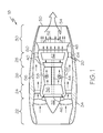
- FIG. 1 is a simplified cross-sectional view a gas turbine engine including a broadband damping system and illustrated in accordance with an exemplary embodiment of the present invention
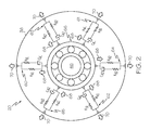
- FIG. 2 is a schematic illustrating a plurality of three parameter axial dampers included within the broadband damping system shown in FIG. 1 ;
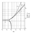
- FIG. 3 is a transmissibility plot of frequency (horizontal axis) versus gain (vertical axis) illustrating the exemplary transmissibility profile of a three parameter axial damper as compared to the transmissibility profiles of a two parameter damper and an undamped device;
- FIG. 4 is a graph of frequency (horizontal axis) versus phase (vertical axis) illustrating the exemplary damping profile of two three parameter axial dampers, which are coupled in parallel and which have varied tunings (solid line), and the exemplary damping profile of two three parameter axial dampers, which are coupled in parallel and which have identical tunings (dashed line);
- FIG. 5 is a graph of frequency (horizontal axis) versus stiffness (vertical axis) illustrating the exemplary stiffness profile of two three parameter axial dampers, which are coupled in parallel and which have varied tunings (solid line), and the exemplary damping profile of two three parameter axial dampers, which are coupled in parallel and which have identical tunings (dashed line); and
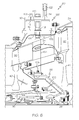
- FIG. 6 is a cross-sectional view taken through a portion of the gas turbine engine shown in FIG. 1 and illustrating an exemplary manner in which one of the three parameter axial dampers included within the broadband damping system shown in FIGs. 1 and 2 can be structurally implemented.
- FIG. 1 is a simplified cross-sectional view a broadband-damped gas turbine engine (GTE) 18 including a broadband damping system 20 and illustrated in accordance with an exemplary embodiment of the present invention.
- GTE 18 is illustrated in FIG. 1 as a two spool turbofan engine including an intake section 22, a compressor section 24, a combustion section 26, a turbine section 28, and an exhaust section 30.
- Intake section 22 includes an intake fan 32 mounted in a nacelle assembly 34.
- compressor section 24 includes a single compressor 36, which is rotatably disposed within an engine case 38 mounted within nacelle assembly 34.
- Turbine section 28 includes a high pressure (HP) turbine 40 and a low pressure (LP) turbine 42, which are rotatably disposed within engine case 38 in flow series.
- Compressor 36 and HP turbine 40 are mounted to opposing ends of an HP shaft or spool 44, and intake fan 32 and LP turbine 42 are mounted to opposing ends of a LP shaft or spool 46.
- LP spool 46 and HP spool 44 are co-axial; that is, LP spool 46 extends through a longitudinal channel provided through HP spool 44.
- Engine case 38 and nacelle assembly 34 terminate in a mixer nozzle 48 and a propulsion nozzle 50, respectively.
- Mixer nozzle 48 cooperates with a centerbody 52 to form an exhaust mixer 54, which mixes hot combustive gas flow received from turbine section 28 with cooler bypass airflow during operation of GTE 18.
- a plurality of rotor bearing assemblies is disposed around HP spool 44 and LP spool 46 at various locations to facilitate high speed rotation of spools 44 and 46 within engine case 38.
- the rotor bearing assemblies commonly assume the form of rolling element bearings disposed around each end of HP spool 44 and LP spool 46.
- broadband-damped GTE 18 is offered by way of example only. It will be readily appreciated that embodiments of the present invention are equally applicable to various other types of gas turbine engine including, but not limited to, other types of turbofan, turboprop, turboshaft, and turbojet engines, as well as to other types of turbomachinery. Furthermore, the particular structure of GTE 18 will inevitably vary amongst different embodiments. For example, in certain embodiments, GTE 18 may include an exposed intake fan (referred to as an "open rotor configuration") or may not include an intake fan. In other embodiments, GTE 18 may employ centrifugal compressors or impellers in addition to or in lieu of axial compressors.
- GTE 18 may include a single spool or three spools along with varying numbers of compressors and turbines. While primarily described below as deployed onboard an aircraft, GTE 18 is by no means limited to deployment onboard any particular platform and may also be deployed onboard other types of vehicles (e.g., watercraft and ground vehicles, such as tanks), included within auxiliary power units, or included within industrial power generators.
- vehicles e.g., watercraft and ground vehicles, such as tanks
- air is drawn into intake section 22 and accelerated by intake fan 32.
- a portion of the accelerated air is directed through a bypass flow passage 56, which is provided between nacelle assembly 34 and engine case 38 and conducts this airflow over and around engine case 38.
- the remaining portion of air exhausted from intake fan 32 is directed into compressor section 36 and compressed by compressor 36 to raise the temperature and pressure of the core airflow.
- the hot, compressed airflow is supplied to combustion section 26 wherein the air is mixed with fuel and combusted utilizing one or more combustors 58 included within section 26.
- the combustive gasses expand rapidly and flow through turbine section 28 to rotate HP turbine 40 and LP turbine 42.
- turbines 40 and 42 drives the rotation of spools 44 and 46, respectively, which, in turn, drives the rotation of compressor 36 and intake fan 32.
- the combustive gas flow is then directed into exhaust section 30 wherein mixer 54 mixes the combustive gas flow with the cooler bypass air received from bypass flow passages 56. Finally, the combustive gas flow is exhausted from GTE 18 through propulsion nozzle 50 to produce forward thrust.
- vibrations are produced during rotation of spools 44 and 46, and transmitted through the non-illustrated rotor bearing assemblies, through engine case 38, and ultimately to the aircraft fuselage.
- the transmission of vibrations to the fuselage can decrease passenger comfort, detract from engine performance, and limit the operational lifespan of the rotor bearing assemblies and other engine components.
- Broadband damping system 20 reduces the magnitude of vibrations of the rotor system, as well as the vibratory forces transmitted from the rotor assembly to engine case 38 over a broad bandwidth as compared to conventional bearing support dampers, such as squeeze film dampers.
- broadband damping system 20 is able to provide highly effective vibration attenuation through multiple rotor critical modes distributed across the frequency range of the rotor assembly during operation of GTE 18.
- broadband damping system 20 provides a highly linear and independently-tunable stiffness profile.
- broadband damping system 20 can be tuned to provide a relatively high static and dynamic stiffness to improve rotor centerline control and thereby improve the overall efficiency of GTE 18.
- the manner in which broadband damping system 20 is able damp vibrations over a relatively broad bandwidth is described more fully below conjunction with FIGs. 2-5 . While described below in conjunction with a gas turbine engine, it is emphasized that embodiments of broadband damping system 20 can be utilized in conjunction with other types of turbomachinery including, for example, turbochargers.
- FIG. 2 is a schematic diagram illustrating a plurality of three parameter axial dampers 60-65 included within broadband damping system 20.
- axial damper refers to a damper or vibration isolator having at least a single degree of freedom and provides damping in at least an axial direction, although the possibility that axial dampers 60-65 could have multiple degrees of freedoms is by no means excluded.
- Axial dampers 60-65 are kinetically coupled between engine case 38 and a rotor bearing assembly 66, as taken along a disturbance transmission path extending from rotor bearing assembly 66 to the mounting interface of GTE 18 ( FIG. 1 ).
- Rotor bearing assembly 66 supports a rotatable shaft or spool, which is identified as LP spool 46 in FIG. 2 for the purposes of providing a complete, albeit non-limiting example.
- rotor bearing assembly 66 is generically illustrated as consisting solely of a ball bearing; however, it will be appreciated that rotor bearing assembly 66 may include any number and type of rotor bearings, including other types of rolling element bearings (e.g., roller bearings), and any number of additional structural elements supportive of or otherwise coupled to the rotor bearing or bearings.
- Axial dampers 60-65 are circumferentially arranged or spaced around the rotational axis of rotor bearing assembly 66 and, more generally, the rotational axis of the rotor assembly in which LP spool 46 is included.
- axial dampers 60-65 assume the form of or include elongated struts, which extend radially outward from rotor bearing assembly 66 in a radially spoked configuration.
- axial dampers 60-65 provide damping in two degrees of freedom within a plane (the X-Y plane) substantially orthogonal to the rotational axis of the rotor assembly and to the engine centerline (the Z-axis).
- axial dampers 60-65 collectively provide damping along vertical and lateral axes substantially parallel with the yaw and pitch axes, respectively, of the host aircraft on which GTE 18 ( FIG. 1 ) is deployed.
- Broadband damping system 20 includes at least four axial dampers, which are divided into two separately-tuned groupings or sets each including at least two axial dampers, as described in detail below.
- broadband damping system 20 includes six dampers 60-65, which are symmetrically arranged around the rotor bearing assembly 66 such that dampers 60-65 are spaced apart at regular intervals of approximately 60 degrees.
- a symmetrical spacing provides a highly stable multi-point mount supporting rotor bearing assembly 66 and LP spool 46.
- axial dampers 60-65 may be asymmetrically arranged around rotor bearing assembly 66 such to impart broadband damping system 20 with varying stiffness and damping properties in different radial directions.
- axial dampers 60-65 may be asymmetrically arranged around rotor bearing assembly 66 to provide an anisotropic stiffness better accommodating known rotordynamic issues; e.g., to counteract static loading due to the weight of GTE 18 and thereby prevent gravity sag and to better accommodate high magnitude impact forces that may occur in the downward direction during aircraft landing.
- dampers 60-65 may have stiffness and damping properties that are individually tuned to provide such anisotropic properties.
- each three parameter axial damper includes three mechanical members: (i) a first spring member (the main spring), which is coupled between spool 46 and engine case 38; (ii) a second spring member (the tuning spring), which is coupled between spool 46 and engine case 38 in parallel with the tuning spring; and (iii) a damper member, which is coupled between spool 46 and engine case 38 in parallel with the main spring and in series with the tuning spring.
- the main spring and tuning spring have spring rates of K A and K B , respectively.
- the damper has a damping constant of C A .
- three parameter devices can be tuned to provide superior damping characteristics (i.e., a lower overall transmissibility) as compared to undamped devices and two parameter devices over a given frequency range.
- the input motion is the radial displacement of rotor bearing assembly 66, as represented in FIG. 2 by arrows 68; and the output motion is the radial displacement of engine case 38, as represented in FIG. 2 by arrows 70.
- FIG. 3 is a transmissibility plot illustrating the damping characteristics of three parameter axial damper (curve 72) as compared to a two parameter damper (curve 74) and an undamped device (curve 76).
- the undamped device (curve 76) provides a relatively high peak gain at the resonant frequency, which, in the illustrated example, is moderately less than 10 Hertz (Hz).
- the two parameter device (curve 74) provides a significantly lower peak gain at the threshold frequency, but an undesirably gradual decrease in gain with increasing frequency after the threshold frequency has been surpassed (referred to as "roll-off").
- the roll-off of the two parameter device is approximately -20 decibel per decade ("dB/decade").
- the three parameter device provides a low peak gain substantially equivalent to that achieved by the two parameter device (curve 74) and further provides a relatively steep roll-off of about -40 dB/decade.
- the three parameter device (curve 72) thus provides a significantly lower transmissibility at higher frequencies, as quantified in FIG. 3 by the area 80 bounded by curves 72 and 74.
- Dampers 60-65 are divided into two groupings or sets: a first set of three parameter axial dampers 60-62 and a second set of three parameter axial dampers 63-65.
- the sets of axial dampers are tuned such that axial dampers 60-62 provide peak damping at a different frequency as compared to axial dampers 63-65; e.g., in preferred embodiments, the peak damping frequency of axial dampers 60-62 and the peak damping frequency of axial dampers 63-65 differs by a factor of at least about 10. This may be more fully appreciated by referring to FIG.
- FIG. 4 is a graph of frequency (horizontal axis) versus phase (vertical axis) illustrating the exemplary damping profile of a pair of three parameter axial dampers, which are coupled in parallel and which are disparately-tuned to provide peak damping at a frequency less than 100 Hz and a frequency greater than a 1000 Hz, versus the exemplary damping profile of a pair of three parameter axial dampers, which are coupled in parallel and which are identically-tuned to provide peak damping at a single frequency between 100 and 1000 Hz.
- a minimum damping threshold identified in FIG. 4 by horizontal line 82
- a targeted frequency range identified in FIG.
- the targeted frequency range may correspond with the operational frequency range of the rotor assembly or, instead, may only encompass a portion thereof.
- the damping profile of the identically-tuned dampers (dashed line) peaks near the midpoint of the targeted frequency range, but tapers off rapidly in either direction.
- the identically-tuned dampers thus provide exceptionally and unnecessarily high damping at critical mode C 3 and acceptable damping at nearby critical modes C 2 and C 4 , but provide relatively poor damping at outlying critical modes C 1 and C 5 .
- the disparately-tuned dampers provide damping exceeding the minimum damping threshold over the entirety of the targeted frequency range and encompassing all rotor critical modes C 1 -C 5 .
- dampers 60-65 can be selected in any manner that provides the above-described disparity in peak damping.
- each of the dampers included within damper set 60-62 will be tuned to have parameters that are substantially identical, as will each of the dampers included within damper set 63-65.
- each damper within the first set of three parameter axial dampers 60-62 can be tuned to have a main spring rate approximately equal to K A1 , a tuning spring rate approximately equal to K B1 , and a damping constant approximately equal to C A1
- each damper included the second set of three parameter axial dampers can be tuned to have a main spring rate approximately equal to K A2 , a tuning spring rate approximately equal to K B2 , and a damping constant approximately equal to C A2 .
- at least one of the K A1 , K B1 , and C A1 will vary with respect to K A2 , K B2 , and C A2 , respectively.
- K B1 and C A1 will typically differ from K B2 and C A2 , respectively, by at least 10%.
- K B1 will exceed K B2 by a factor of two or more.
- C A1 will typically be significantly less than C A2 ; e.g., in certain embodiments, C A2 may exceed C A1 by a factor of at least 10. In such embodiments, K A1 and K A2 may be approximately equal.
- K A1 and K A2 may be approximately equal.
- the identically-tuned dampers (dashed line) have a main spring rate (K A ) of approximately 17.5E6 N/m, a tuning spring rate (K B ) of approximately 87.5E6 N/m, and a damping coefficient (C A ) of approximately 17.5E3 N/(m/s).
- the first damper in the pair of disparately-tuned dampers has a K A1 value of approximately 17.5E6 N/m, a K B1 rate of approximately 17.5E6 N/m, and a C A1 coefficient of approximately 3.5E3 N/(m/s); while the second disparately-tuned damper has a K A2 rate of approximately 17.5E6 N/m, a K B2 rate of approximately 43.8E6 N/m, and a C A2 coefficient of approximately 87.5E3 N/(m/s).
- FIG. 5 is a graph of frequency (horizontal axis) versus stiffness (vertical axis) illustrating the exemplary stiffness profiles for the identically-tuned damper (dashed line) and the disparately-tuned dampers (solid line) described above in conjunction with FIG. 4 .
- a doubled-headed arrow 84 identifies an exemplary targeted frequency range, which may encompass the entirety or only a portion of operational frequency range of the rotor assembly.
- a desired minimum dynamic stiffness threshold is further identified in FIG. 5 by vertical line 86.
- the stiffness profile of the disparately-tuned dampers exceeds the desired dynamic stiffness threshold for a greater portion of the targeted frequency range than does the stiffness profile of the identically-tuned dampers (dashed line).
- the disparately-tuned dampers thus provide an improved stiffness profile that enables better centerline control of the rotor assembly over the operational frequency range, which, in turn, results in an overall increase in engine efficiency.
- Both the identically-tune and disparately-tuned systems in FIG. 5 provide the same static stiffness, therefore producing the same centerline motion for quasi-static or low frequency inputs.
- FIG. 6 is a cross-sectional view taken through a portion of broadband-damped gas turbine engine 18 ( FIGs. 1 and 2 ) and illustrating one manner in which axial damper 60 (and thus axial dampers 61-65) can be structurally implemented.
- the illustrated portion of GTE 18 includes a first rotating blade 90 included within HP turbine 40, a second rotating blade 92 included within LP turbine 42, a stationary blade 94 positioned between HP turbine 40 and LP turbine 42, and a rotor bearing assembly 66.
- Rotor bearing assembly 66 includes a first rotor bearing 96, a second rotor bearing 98, and a stationary bearing housing member 100 (e.g., a conical wall).
- Axial damper 60 includes a main damper unit 102, which is mounted to the exterior of engine case 38; and an elongated strut 104, the outer radial end of which attaches to main damper unit 102 through a radial opening 106 provided in engine case 38.
- Strut 104 extends radially inward from main damper unit 102, through stator vane 94, and to bearing housing member 100.
- the inner radial end of strut 104 is affixed to bearing housing member 100 utilizing, for example, a plurality of bolts 108 or other such fasteners.
- Main damper unit 102 includes a damper housing 110 containing first and second radially-compliant flexures 112 and 114.
- Flexure 114 is affixed to the outer end of strut 104 by way of a radial adjustment device 116, and flexure 112 is fixedly coupled to the outer end of strut 104 by a radial extension piece 118.
- radial adjustment device 116 enables the radial position of strut 104, and thus the radial position of rotor bearing assembly 66, to be fine-tuned after assembly of GTE 18 ( FIG. 1 ) to provide centerline adjustment; i.e., precise centering of the rotor assembly spool.
- flexures 112 and 114 are each mechanically coupled between strut 104 and damper housing 110 or, more generally, between rotor bearing assembly 66 and engine case 38. Flexure 112 cooperates with the interior of housing 110 to define a hydraulic chamber 120 within main damper unit 102, which is filled with a silicon oil or other suitable damping fluid. Hydraulic chamber 120 is fluidly coupled to a bellows 122 by way of a fluid conduit or channel 124. Collectively, hydraulic chamber 120, bellows 122, and conduit 124, along with the damping fluid contained therein, form a damper device 126.
- damper device 126 may include an independent thermal compensation device (e.g., a spring-loaded piston) fluidly coupled to hydraulic chamber 120. Damper device 126 may be further equipped with include a fill port 128 to permit post-assembly filling of hydraulic chamber 120.
- main damper unit 102 servers as a three parameter device providing two vibration transmission paths to engine case 38.
- the first vibration transmission path extends from strut 104 through flexure 114 and to damper housing 110 and, therefore, to engine case 38. Vibrations traveling along this path are effectively shunted around flexure 112 and hydraulic chamber 120. Vibrations transmitted along this path are attenuated by deflection of flexure 114, which serves as the main spring and is wholly or predominately determinative the main spring rate K A .
- the second vibration transmission path extends from strut 104, through flexure 112, through hydraulic chamber 120, and to damper housing 110. Vibrations transmitted along this path are thus attenuated both by deflection of flexure 112, which functions as the tuning spring, and by the corresponding displacement of damping fluid within damper device 126.
- Flexure 112 is a small contributor to the overall K A parameter, and is additionally part of the parameter K B in that K B is determined by the compliance of the containment chamber generally formed by flexures 110 and 112 and bellows 122.
- damper device 126 is wholly or predominately determinative of the damper constant C A .
- axial damper 60 The structural implementation of axial damper 60 described above in conjunction with FIG. 6 is provided by way of non-limiting example only.
- axial dampers 60-65 may assume other forms.
- three parameter axial dampers generally suitable for usage as axial dampers 60-65 are commercially utilized in conjunction within precision isolation systems deployed onboard satellite and other spacecraft.
- An example of an axial three parameter axial damper or vibration isolator is the D-STRUT® isolator developed and commercially marketed by Honeywell, Inc., currently headquartered in Morristown, New Jersey.
- each three parameter strut may be positioned within GTE 18 in essentially in the same manner as is strut 104, thereby eliminating the need for an case-mounted damper unit, such as main damper unit 102.
- a gas turbine engine including a broadband damping system having an increased damping bandwidth, as taken over the frequency range of the engine's rotor assembly, to more effectively attenuate vibrations emitted from the rotor assembly through multiple critical modes.
- the above-described broadband damping system provided substantially linear damping profiles to permit high damping through a broad range of frequencies and loading conditions (amplitudes), while also providing a substantially linear and independently-tunable stiffness profile to improve rotor centerline control. While described above primarily in conjunction with a gas turbine engine, it will be appreciated that embodiments of the broadband damping system are also well-suited for usage in conjunction with other types of turbomachinery, including turbochargers.
- the broadband damping system may include first and second sets of three parameter axial dampers angularly spaced around the rotational axis of the turbomachine's rotor assembly and positioned between the rotor assembly and the turbomachine's stationary housing, as taken along a vibration transmission path.
- the method includes the steps of providing a rotor assembly and an engine case (e.g., engine case 38 shown in FIGs. 1 , 2 , and 6 ); identifying a plurality of rotor critical modes of the rotor assembly over the operational range of the gas turbine engine; tuning first and second sets of three parameter axial dampers (e.g., dampers 60-65 shown in FIG. 5 ) to provide peak damping at different frequencies distributed over a target frequency range encompassing the plurality of rotor critical modes, as graphically indicated in FIG.
- an engine case e.g., engine case 38 shown in FIGs. 1 , 2 , and 6
- tuning first and second sets of three parameter axial dampers e.g., dampers 60-65 shown in FIG. 5
- the first and second sets of three parameter axial dampers may be circumferentially spaced around the rotor assembly at predetermined intervals such that the first set of three parameter axial dampers is interspersed with the second set of three parameter axial dampers, as generally shown in FIG. 2 .
Landscapes
- Engineering & Computer Science (AREA)
- General Engineering & Computer Science (AREA)
- Mechanical Engineering (AREA)
- Chemical & Material Sciences (AREA)
- Combustion & Propulsion (AREA)
- Physics & Mathematics (AREA)
- Acoustics & Sound (AREA)
- Aviation & Aerospace Engineering (AREA)
- Turbine Rotor Nozzle Sealing (AREA)
- Vibration Prevention Devices (AREA)
- Support Of The Bearing (AREA)
Applications Claiming Priority (1)
| Application Number | Priority Date | Filing Date | Title |
|---|---|---|---|
| US13/219,287 US8992161B2 (en) | 2011-08-26 | 2011-08-26 | Gas turbine engines including broadband damping systems and methods for producing the same |
Publications (3)
| Publication Number | Publication Date |
|---|---|
| EP2562367A2 true EP2562367A2 (de) | 2013-02-27 |
| EP2562367A3 EP2562367A3 (de) | 2015-06-17 |
| EP2562367B1 EP2562367B1 (de) | 2017-10-11 |
Family
ID=46754913
Family Applications (1)
| Application Number | Title | Priority Date | Filing Date |
|---|---|---|---|
| EP12181431.3A Active EP2562367B1 (de) | 2011-08-26 | 2012-08-22 | Gasturbinenmotoren mit Breitbanddämpfungssystemen und Herstellungsverfahren dafür |
Country Status (5)
| Country | Link |
|---|---|
| US (1) | US8992161B2 (de) |
| EP (1) | EP2562367B1 (de) |
| JP (1) | JP5956290B2 (de) |
| KR (1) | KR101924334B1 (de) |
| TW (1) | TWI583864B (de) |
Families Citing this family (21)
| Publication number | Priority date | Publication date | Assignee | Title |
|---|---|---|---|---|
| US8992161B2 (en) | 2011-08-26 | 2015-03-31 | Honeywell International Inc. | Gas turbine engines including broadband damping systems and methods for producing the same |
| US9046001B2 (en) | 2011-08-29 | 2015-06-02 | Honeywell International Inc. | Annular bearing support dampers, gas turbine engines including the same, and methods for the manufacture thereof |
| US9297438B2 (en) * | 2012-01-25 | 2016-03-29 | Honeywell International Inc. | Three parameter damper anisotropic vibration isolation mounting assembly |
| US9384668B2 (en) | 2012-05-09 | 2016-07-05 | Singularity University | Transportation using network of unmanned aerial vehicles |
| US9702404B2 (en) | 2015-10-28 | 2017-07-11 | United Technologies Corporation | Integral centering spring and bearing support and method of supporting multiple damped bearings |
| CN108290633A (zh) * | 2015-11-10 | 2018-07-17 | 马特耐特公司 | 使用无人航空载具进行运输的方法和系统 |
| US11002335B2 (en) * | 2016-11-08 | 2021-05-11 | General Electric Company | Controllable magneto-rheological device for gas turbine engine |
| JP6990639B2 (ja) * | 2018-09-26 | 2022-01-12 | 本田技研工業株式会社 | ターボファンエンジン |
| US11105223B2 (en) | 2019-08-08 | 2021-08-31 | General Electric Company | Shape memory alloy reinforced casing |
| US12441491B2 (en) | 2020-04-17 | 2025-10-14 | Sonin Hybrid, LLC | Powertrain for aerial vehicle |
| CN111859730B (zh) * | 2020-06-05 | 2023-10-13 | 合肥通用机械研究院有限公司 | 一种燃料电池离心压缩机转子构形优化设计方法 |
| USD1045668S1 (en) | 2020-08-24 | 2024-10-08 | Sonin Hybrid, LLC | Drone |
| US11674397B2 (en) * | 2020-11-18 | 2023-06-13 | General Electric Company | Variable stiffness damper system |
| US11492926B2 (en) * | 2020-12-17 | 2022-11-08 | Pratt & Whitney Canada Corp. | Bearing housing with slip joint |
| US11879498B2 (en) * | 2021-01-04 | 2024-01-23 | General Electric Company | Rotor damping devices for a turbomachine |
| FR3122694B1 (fr) * | 2021-05-07 | 2024-03-29 | Safran Aircraft Engines | Turboréacteur muni d’un ensemble de fixation disposé sur un carter de soufflante |
| CN113567075A (zh) * | 2021-08-26 | 2021-10-29 | 华能国际电力股份有限公司 | 一种非接触式全尺寸叶片-轮盘系统振动阻尼测试系统及方法 |
| CN116293795B (zh) * | 2021-12-06 | 2025-05-16 | 通用电气阿维奥有限责任公司 | 用于燃气涡轮燃烧器应用的圆顶集成声学阻尼器 |
| FR3131349B1 (fr) * | 2021-12-24 | 2023-11-10 | Safran Helicopter Engines | Turbomachine d’aéronef |
| EP4568895A1 (de) * | 2022-08-09 | 2025-06-18 | Pete Bitar | Kompakte und leichte drohnenabgabevorrichtung mit lichtbogendrohnensystem mit luftkanalluftantriebssystem und relativ geringer flugverfolgbarkeit |
| FR3148060A1 (fr) * | 2023-04-24 | 2024-10-25 | Safran Power Units | Agencement de conduit d’un flux d’air entre des carters annulaires d’un ensemble propulsif d’aeronef |
Family Cites Families (69)
| Publication number | Priority date | Publication date | Assignee | Title |
|---|---|---|---|---|
| US2967739A (en) | 1958-01-23 | 1961-01-10 | Hoffmann August | Damage-proof journalling of bearings for rapidly rotating shafts |
| US3015523A (en) | 1960-05-04 | 1962-01-02 | Westinghouse Electric Corp | Vibration isolating bearing support |
| FR2076450A5 (de) | 1970-01-15 | 1971-10-15 | Snecma | |
| DE2104612A1 (de) | 1970-02-02 | 1971-08-12 | Commissariat Energie Atomique | Fuhrung zur selbsttätigen Ausrichtung eines zu fuhrenden Bauteils |
| US3809340A (en) | 1972-12-26 | 1974-05-07 | A Dolgy | Devices for mounting an engine on an aircraft pylon |
| US3813776A (en) | 1973-05-15 | 1974-06-04 | Mccullough Corp | Vibration isolation system particularly adapted for use with a chain saw |
| US4370094A (en) | 1974-03-21 | 1983-01-25 | Maschinenfabrik Augsburg-Nurnberg Aktiengesellschaft | Method of and device for avoiding rotor instability to enhance dynamic power limit of turbines and compressors |
| US4214796A (en) | 1978-10-19 | 1980-07-29 | General Electric Company | Bearing assembly with multiple squeeze film damper apparatus |
| US4668108A (en) | 1985-03-22 | 1987-05-26 | General Electric Company | Bearing having anisotropic stiffness |
| US4872767A (en) | 1985-04-03 | 1989-10-10 | General Electric Company | Bearing support |
| US5028001A (en) | 1987-03-13 | 1991-07-02 | General Electric Company | Method of vibration isolating an aircraft engine |
| US5421655A (en) | 1987-05-29 | 1995-06-06 | Kmc, Inc. | Fluid dampened support having variable stiffness and damping |
| US5531522A (en) | 1987-05-29 | 1996-07-02 | Kmc, Inc. | Fluid dampened support having variable stiffness and damping |
| US5603574A (en) * | 1987-05-29 | 1997-02-18 | Kmc, Inc. | Fluid dampened support having variable stiffness and damping |
| US4952076A (en) | 1989-07-21 | 1990-08-28 | United Technologies Corporation | Fluid damper for thrust bearing |
| US5065959A (en) | 1989-11-21 | 1991-11-19 | The Boeing Company | Vibration damping aircraft engine attachment |
| US5044781A (en) | 1990-07-26 | 1991-09-03 | United Technologies Corporation | Spring supported damping system |
| US5088840A (en) | 1990-07-26 | 1992-02-18 | United Technologies Corporation | Dashpot damper |
| US5305981A (en) | 1991-10-31 | 1994-04-26 | Honeywell Inc. | Multiaxis vibration isolation system |
| US5284011A (en) | 1992-12-14 | 1994-02-08 | General Electric Company | Damped turbine engine frame |
| US5332070A (en) * | 1993-04-21 | 1994-07-26 | Honeywell Inc. | Three parameter viscous damper and isolator |
| DE4317062C2 (de) | 1993-05-21 | 1995-08-17 | Freudenberg Carl Fa | Kardanwellenlager |
| US5484120A (en) | 1994-03-11 | 1996-01-16 | Sundstrand Corporation | Support strut for ram air driven turbine |
| JPH08326557A (ja) | 1995-05-30 | 1996-12-10 | Ishikawajima Harima Heavy Ind Co Ltd | ガスタービンの支持構造 |
| US5613781A (en) | 1996-04-30 | 1997-03-25 | Dresser-Rand Company | Hanging spring supported squeeze film damping system for shaft bearing |
| US6002778A (en) | 1996-08-07 | 1999-12-14 | Lord Corporation | Active structural control system and method including active vibration absorbers (AVAS) |
| US5947240A (en) | 1997-02-03 | 1999-09-07 | Honeywell, Inc. | Load vibration isolation apparatus |
| US5947457A (en) * | 1997-04-08 | 1999-09-07 | Lord Corporation | Fluid-filled active vibration absorber |
| US5810319A (en) | 1997-04-17 | 1998-09-22 | Applied Power Inc. | Adaptively tuned vibration absorber with dual flexures |
| US6191510B1 (en) | 1997-12-19 | 2001-02-20 | 3M Innovative Properties Company | Internally damped stator, rotor, and transformer and a method of making |
| DE19834111A1 (de) | 1998-07-29 | 2000-02-03 | Asea Brown Boveri | Radiallager |
| US6328293B1 (en) | 1998-09-18 | 2001-12-11 | Lord Corporation | Multi-linkage suspension system including outboard isolators |
| FR2795386B1 (fr) | 1999-06-22 | 2001-11-09 | Eurocopter France | Dispositif de suspension antivibratoire avec ressorts en torsion entre batteurs et structure, pour helicoptere |
| US6325546B1 (en) | 1999-11-30 | 2001-12-04 | General Electric Company | Fan assembly support system |
| US6806604B2 (en) | 2000-07-13 | 2004-10-19 | Kendro Laboratory Products Gmbh | Centrifuge with a magnetically stabilized rotor for centrifugal goods |
| US6394387B1 (en) | 2000-12-22 | 2002-05-28 | Pratt & Whitney Canada Corp. | Rotor shaft support and drive arrangement |
| GB2375513B (en) | 2001-05-19 | 2005-03-23 | Rolls Royce Plc | A mounting arrangement for a gas turbine engine |
| US20030132077A1 (en) | 2002-01-15 | 2003-07-17 | Davis Toren S. | Tuned mass damper using a hexapod |
| US6682219B2 (en) | 2002-04-03 | 2004-01-27 | Honeywell International Inc. | Anisotropic support damper for gas turbine bearing |
| BR0300928A (pt) | 2002-04-04 | 2004-08-17 | Dana Corp | Conjunto de mancal central |
| US6834841B2 (en) * | 2002-07-03 | 2004-12-28 | Honeywell International Inc. | Method and system for decoupling structural modes to provide consistent control system performance |
| US6789998B2 (en) | 2002-09-06 | 2004-09-14 | Honeywell International Inc. | Aperiodic struts for enhanced blade responses |
| FR2864995B1 (fr) | 2004-01-12 | 2008-01-04 | Snecma Moteurs | Support de palier a double raideur |
| US7121729B2 (en) | 2004-03-15 | 2006-10-17 | Honeywell International, Inc. | Damped bearing cage |
| US20050217954A1 (en) * | 2004-03-31 | 2005-10-06 | Hindle Timothy A | Viscous isolation and damping strut utilizing a fluid mass effect |
| US7066651B2 (en) | 2004-07-09 | 2006-06-27 | Rotating Machinery Technology Inc | Disc spring centering device for squeeze film dampers |
| US7631839B1 (en) | 2004-08-20 | 2009-12-15 | Lockheed Martin Corporation | Enhanced multiple instrument distributed aperture sensor |
| US7384199B2 (en) | 2004-08-27 | 2008-06-10 | General Electric Company | Apparatus for centering rotor assembly bearings |
| US8001764B2 (en) | 2004-09-17 | 2011-08-23 | Aurora Flight Sciences Corporation | Vibration isolation engine mount system and method for ducted fans |
| US7182188B2 (en) * | 2005-02-16 | 2007-02-27 | Honeywell International, Inc. | Isolator using externally pressurized sealing bellows |
| US20060204153A1 (en) | 2005-03-10 | 2006-09-14 | Honeywell International Inc. | Compact resilient anisotropic support for bearing |
| EP1866203B1 (de) | 2005-04-04 | 2011-06-08 | Lord Corporation | Lagerungssystem für eine flugzeughilfsturbine zur isolierung einer flugzeughilfsturbine |
| US7625121B2 (en) * | 2005-09-28 | 2009-12-01 | Elliott Company | Bearing assembly and centering support structure therefor |
| US7445094B1 (en) * | 2005-10-11 | 2008-11-04 | The United States Of America As Represented By The Secretary Of The Air Force | Passive magneto-rheological vibration isolation apparatus |
| GB0622405D0 (en) | 2006-11-10 | 2006-12-20 | Rolls Royce Plc | A turbine engine mounting arrangement |
| US20080148708A1 (en) | 2006-12-20 | 2008-06-26 | General Electric Company | Turbine engine system with shafts for improved weight and vibration characteristic |
| US7731426B2 (en) | 2007-04-27 | 2010-06-08 | Honeywell International Inc. | Rotor supports and systems |
| US8973724B2 (en) * | 2007-07-17 | 2015-03-10 | Honeywell International Inc. | Vibration isolators and isolation systems |
| US8118570B2 (en) | 2007-10-31 | 2012-02-21 | Honeywell International Inc. | Anisotropic bearing supports for turbochargers |
| US8511986B2 (en) | 2007-12-10 | 2013-08-20 | United Technologies Corporation | Bearing mounting system in a low pressure turbine |
| US8118251B2 (en) | 2008-01-18 | 2012-02-21 | United Technologies Corporation | Mounting system for a gas turbine engine |
| US7950633B2 (en) | 2008-08-07 | 2011-05-31 | Drs Rsta, Inc. | Vibration isolator system |
| JP2010133530A (ja) * | 2008-12-08 | 2010-06-17 | Mitsubishi Heavy Ind Ltd | 軸受構造及び該軸受構造を備えた過給機 |
| US8256750B2 (en) * | 2009-02-18 | 2012-09-04 | Honeywell International Inc. | Vibration isolation mounting assembly |
| WO2010128896A1 (en) | 2009-05-07 | 2010-11-11 | Volvo Aero Corporation | A strut and a gas turbine structure comprising the strut |
| US8727699B2 (en) * | 2009-12-29 | 2014-05-20 | Rolls-Royce Corporation | Rotating machinery with damping system |
| US8992161B2 (en) | 2011-08-26 | 2015-03-31 | Honeywell International Inc. | Gas turbine engines including broadband damping systems and methods for producing the same |
| US9046001B2 (en) | 2011-08-29 | 2015-06-02 | Honeywell International Inc. | Annular bearing support dampers, gas turbine engines including the same, and methods for the manufacture thereof |
| US20130067931A1 (en) | 2011-09-21 | 2013-03-21 | Honeywell International Inc. | Gas turbine engine assemblies including strut-based vibration isolation mounts and methods for producing the same |
-
2011
- 2011-08-26 US US13/219,287 patent/US8992161B2/en active Active
-
2012
- 2012-08-22 EP EP12181431.3A patent/EP2562367B1/de active Active
- 2012-08-23 TW TW101130710A patent/TWI583864B/zh active
- 2012-08-24 JP JP2012185305A patent/JP5956290B2/ja active Active
- 2012-08-24 KR KR1020120093024A patent/KR101924334B1/ko active Active
Non-Patent Citations (1)
| Title |
|---|
| None |
Also Published As
| Publication number | Publication date |
|---|---|
| KR20130025333A (ko) | 2013-03-11 |
| US20130051981A1 (en) | 2013-02-28 |
| US8992161B2 (en) | 2015-03-31 |
| JP2013050104A (ja) | 2013-03-14 |
| EP2562367B1 (de) | 2017-10-11 |
| KR101924334B1 (ko) | 2018-12-03 |
| TWI583864B (zh) | 2017-05-21 |
| TW201319381A (zh) | 2013-05-16 |
| JP5956290B2 (ja) | 2016-07-27 |
| EP2562367A3 (de) | 2015-06-17 |
Similar Documents
| Publication | Publication Date | Title |
|---|---|---|
| EP2562367B1 (de) | Gasturbinenmotoren mit Breitbanddämpfungssystemen und Herstellungsverfahren dafür | |
| US9297438B2 (en) | Three parameter damper anisotropic vibration isolation mounting assembly | |
| EP2565394B1 (de) | Gasturbinenmotoren mit ringförmigen Lagerstützdämfungen. | |
| EP2400119B1 (de) | Rotorspitzenabstand- und wellendynamik-system für ein gasturbinentriebwerk | |
| US9476320B2 (en) | Gas turbine engine aft bearing arrangement | |
| EP3236095B1 (de) | Lager | |
| US20130067931A1 (en) | Gas turbine engine assemblies including strut-based vibration isolation mounts and methods for producing the same | |
| US10036279B2 (en) | Thrust bearing | |
| EP3049655B1 (de) | Lageranordnung für einen gasturbinenmotor, die radialvibrationen in axialvibrationen verwandelt | |
| WO2014163695A1 (en) | Gas turbine engine, machine and self-aligning foil bearing system | |
| JP2019518176A (ja) | ガス軸受アセンブリ用の流体充填ダンパー | |
| US10738653B2 (en) | Squeeze film damper assemblies | |
| US20250207499A1 (en) | Airfoil vibration damping apparatus | |
| US20170016349A1 (en) | Gas turbine engine | |
| US20240240651A1 (en) | Damping device for damping shaft vibration | |
| US12421869B2 (en) | Torsional vibration damper mechanism for gas turbine engine | |
| EP4265530B1 (de) | Passives drehen einer rotierenden struktur eines gasturbinenmotors während des transports | |
| US11976593B1 (en) | Bearing assembly |
Legal Events
| Date | Code | Title | Description |
|---|---|---|---|
| PUAI | Public reference made under article 153(3) epc to a published international application that has entered the european phase |
Free format text: ORIGINAL CODE: 0009012 |
|
| 17P | Request for examination filed |
Effective date: 20120822 |
|
| AK | Designated contracting states |
Kind code of ref document: A2 Designated state(s): AL AT BE BG CH CY CZ DE DK EE ES FI FR GB GR HR HU IE IS IT LI LT LU LV MC MK MT NL NO PL PT RO RS SE SI SK SM TR |
|
| AX | Request for extension of the european patent |
Extension state: BA ME |
|
| PUAL | Search report despatched |
Free format text: ORIGINAL CODE: 0009013 |
|
| AK | Designated contracting states |
Kind code of ref document: A3 Designated state(s): AL AT BE BG CH CY CZ DE DK EE ES FI FR GB GR HR HU IE IS IT LI LT LU LV MC MK MT NL NO PL PT RO RS SE SI SK SM TR |
|
| AX | Request for extension of the european patent |
Extension state: BA ME |
|
| RIC1 | Information provided on ipc code assigned before grant |
Ipc: F16F 15/02 20060101ALI20150512BHEP Ipc: F01D 5/10 20060101ALI20150512BHEP Ipc: F01D 25/04 20060101AFI20150512BHEP Ipc: F16F 15/023 20060101ALI20150512BHEP |
|
| 17Q | First examination report despatched |
Effective date: 20150612 |
|
| RAP1 | Party data changed (applicant data changed or rights of an application transferred) |
Owner name: HONEYWELL INTERNATIONAL INC. |
|
| RIC1 | Information provided on ipc code assigned before grant |
Ipc: F16F 15/02 20060101ALI20170216BHEP Ipc: F01D 5/10 20060101ALI20170216BHEP Ipc: F16F 15/023 20060101ALI20170216BHEP Ipc: F01D 25/04 20060101AFI20170216BHEP |
|
| GRAP | Despatch of communication of intention to grant a patent |
Free format text: ORIGINAL CODE: EPIDOSNIGR1 |
|
| INTG | Intention to grant announced |
Effective date: 20170425 |
|
| GRAS | Grant fee paid |
Free format text: ORIGINAL CODE: EPIDOSNIGR3 |
|
| GRAA | (expected) grant |
Free format text: ORIGINAL CODE: 0009210 |
|
| AK | Designated contracting states |
Kind code of ref document: B1 Designated state(s): AL AT BE BG CH CY CZ DE DK EE ES FI FR GB GR HR HU IE IS IT LI LT LU LV MC MK MT NL NO PL PT RO RS SE SI SK SM TR |
|
| REG | Reference to a national code |
Ref country code: GB Ref legal event code: FG4D |
|
| REG | Reference to a national code |
Ref country code: CH Ref legal event code: EP |
|
| REG | Reference to a national code |
Ref country code: IE Ref legal event code: FG4D |
|
| REG | Reference to a national code |
Ref country code: AT Ref legal event code: REF Ref document number: 936245 Country of ref document: AT Kind code of ref document: T Effective date: 20171115 |
|
| REG | Reference to a national code |
Ref country code: DE Ref legal event code: R096 Ref document number: 602012038330 Country of ref document: DE |
|
| REG | Reference to a national code |
Ref country code: NL Ref legal event code: MP Effective date: 20171011 |
|
| REG | Reference to a national code |
Ref country code: LT Ref legal event code: MG4D |
|
| REG | Reference to a national code |
Ref country code: AT Ref legal event code: MK05 Ref document number: 936245 Country of ref document: AT Kind code of ref document: T Effective date: 20171011 |
|
| PG25 | Lapsed in a contracting state [announced via postgrant information from national office to epo] |
Ref country code: NL Free format text: LAPSE BECAUSE OF FAILURE TO SUBMIT A TRANSLATION OF THE DESCRIPTION OR TO PAY THE FEE WITHIN THE PRESCRIBED TIME-LIMIT Effective date: 20171011 |
|
| PG25 | Lapsed in a contracting state [announced via postgrant information from national office to epo] |
Ref country code: NO Free format text: LAPSE BECAUSE OF FAILURE TO SUBMIT A TRANSLATION OF THE DESCRIPTION OR TO PAY THE FEE WITHIN THE PRESCRIBED TIME-LIMIT Effective date: 20180111 Ref country code: SE Free format text: LAPSE BECAUSE OF FAILURE TO SUBMIT A TRANSLATION OF THE DESCRIPTION OR TO PAY THE FEE WITHIN THE PRESCRIBED TIME-LIMIT Effective date: 20171011 Ref country code: ES Free format text: LAPSE BECAUSE OF FAILURE TO SUBMIT A TRANSLATION OF THE DESCRIPTION OR TO PAY THE FEE WITHIN THE PRESCRIBED TIME-LIMIT Effective date: 20171011 Ref country code: FI Free format text: LAPSE BECAUSE OF FAILURE TO SUBMIT A TRANSLATION OF THE DESCRIPTION OR TO PAY THE FEE WITHIN THE PRESCRIBED TIME-LIMIT Effective date: 20171011 Ref country code: LT Free format text: LAPSE BECAUSE OF FAILURE TO SUBMIT A TRANSLATION OF THE DESCRIPTION OR TO PAY THE FEE WITHIN THE PRESCRIBED TIME-LIMIT Effective date: 20171011 |
|
| PG25 | Lapsed in a contracting state [announced via postgrant information from national office to epo] |
Ref country code: GR Free format text: LAPSE BECAUSE OF FAILURE TO SUBMIT A TRANSLATION OF THE DESCRIPTION OR TO PAY THE FEE WITHIN THE PRESCRIBED TIME-LIMIT Effective date: 20180112 Ref country code: HR Free format text: LAPSE BECAUSE OF FAILURE TO SUBMIT A TRANSLATION OF THE DESCRIPTION OR TO PAY THE FEE WITHIN THE PRESCRIBED TIME-LIMIT Effective date: 20171011 Ref country code: LV Free format text: LAPSE BECAUSE OF FAILURE TO SUBMIT A TRANSLATION OF THE DESCRIPTION OR TO PAY THE FEE WITHIN THE PRESCRIBED TIME-LIMIT Effective date: 20171011 Ref country code: AT Free format text: LAPSE BECAUSE OF FAILURE TO SUBMIT A TRANSLATION OF THE DESCRIPTION OR TO PAY THE FEE WITHIN THE PRESCRIBED TIME-LIMIT Effective date: 20171011 Ref country code: RS Free format text: LAPSE BECAUSE OF FAILURE TO SUBMIT A TRANSLATION OF THE DESCRIPTION OR TO PAY THE FEE WITHIN THE PRESCRIBED TIME-LIMIT Effective date: 20171011 Ref country code: IS Free format text: LAPSE BECAUSE OF FAILURE TO SUBMIT A TRANSLATION OF THE DESCRIPTION OR TO PAY THE FEE WITHIN THE PRESCRIBED TIME-LIMIT Effective date: 20180211 Ref country code: BG Free format text: LAPSE BECAUSE OF FAILURE TO SUBMIT A TRANSLATION OF THE DESCRIPTION OR TO PAY THE FEE WITHIN THE PRESCRIBED TIME-LIMIT Effective date: 20180111 |
|
| REG | Reference to a national code |
Ref country code: DE Ref legal event code: R097 Ref document number: 602012038330 Country of ref document: DE |
|
| PG25 | Lapsed in a contracting state [announced via postgrant information from national office to epo] |
Ref country code: SK Free format text: LAPSE BECAUSE OF FAILURE TO SUBMIT A TRANSLATION OF THE DESCRIPTION OR TO PAY THE FEE WITHIN THE PRESCRIBED TIME-LIMIT Effective date: 20171011 Ref country code: CZ Free format text: LAPSE BECAUSE OF FAILURE TO SUBMIT A TRANSLATION OF THE DESCRIPTION OR TO PAY THE FEE WITHIN THE PRESCRIBED TIME-LIMIT Effective date: 20171011 Ref country code: EE Free format text: LAPSE BECAUSE OF FAILURE TO SUBMIT A TRANSLATION OF THE DESCRIPTION OR TO PAY THE FEE WITHIN THE PRESCRIBED TIME-LIMIT Effective date: 20171011 Ref country code: DK Free format text: LAPSE BECAUSE OF FAILURE TO SUBMIT A TRANSLATION OF THE DESCRIPTION OR TO PAY THE FEE WITHIN THE PRESCRIBED TIME-LIMIT Effective date: 20171011 |
|
| PLBE | No opposition filed within time limit |
Free format text: ORIGINAL CODE: 0009261 |
|
| STAA | Information on the status of an ep patent application or granted ep patent |
Free format text: STATUS: NO OPPOSITION FILED WITHIN TIME LIMIT |
|
| REG | Reference to a national code |
Ref country code: FR Ref legal event code: PLFP Year of fee payment: 7 |
|
| PG25 | Lapsed in a contracting state [announced via postgrant information from national office to epo] |
Ref country code: RO Free format text: LAPSE BECAUSE OF FAILURE TO SUBMIT A TRANSLATION OF THE DESCRIPTION OR TO PAY THE FEE WITHIN THE PRESCRIBED TIME-LIMIT Effective date: 20171011 Ref country code: IT Free format text: LAPSE BECAUSE OF FAILURE TO SUBMIT A TRANSLATION OF THE DESCRIPTION OR TO PAY THE FEE WITHIN THE PRESCRIBED TIME-LIMIT Effective date: 20171011 Ref country code: SM Free format text: LAPSE BECAUSE OF FAILURE TO SUBMIT A TRANSLATION OF THE DESCRIPTION OR TO PAY THE FEE WITHIN THE PRESCRIBED TIME-LIMIT Effective date: 20171011 Ref country code: PL Free format text: LAPSE BECAUSE OF FAILURE TO SUBMIT A TRANSLATION OF THE DESCRIPTION OR TO PAY THE FEE WITHIN THE PRESCRIBED TIME-LIMIT Effective date: 20171011 |
|
| 26N | No opposition filed |
Effective date: 20180712 |
|
| PG25 | Lapsed in a contracting state [announced via postgrant information from national office to epo] |
Ref country code: SI Free format text: LAPSE BECAUSE OF FAILURE TO SUBMIT A TRANSLATION OF THE DESCRIPTION OR TO PAY THE FEE WITHIN THE PRESCRIBED TIME-LIMIT Effective date: 20171011 |
|
| PG25 | Lapsed in a contracting state [announced via postgrant information from national office to epo] |
Ref country code: MC Free format text: LAPSE BECAUSE OF FAILURE TO SUBMIT A TRANSLATION OF THE DESCRIPTION OR TO PAY THE FEE WITHIN THE PRESCRIBED TIME-LIMIT Effective date: 20171011 |
|
| REG | Reference to a national code |
Ref country code: CH Ref legal event code: PL |
|
| PG25 | Lapsed in a contracting state [announced via postgrant information from national office to epo] |
Ref country code: CH Free format text: LAPSE BECAUSE OF NON-PAYMENT OF DUE FEES Effective date: 20180831 Ref country code: LU Free format text: LAPSE BECAUSE OF NON-PAYMENT OF DUE FEES Effective date: 20180822 Ref country code: LI Free format text: LAPSE BECAUSE OF NON-PAYMENT OF DUE FEES Effective date: 20180831 |
|
| REG | Reference to a national code |
Ref country code: BE Ref legal event code: MM Effective date: 20180831 |
|
| PG25 | Lapsed in a contracting state [announced via postgrant information from national office to epo] |
Ref country code: BE Free format text: LAPSE BECAUSE OF NON-PAYMENT OF DUE FEES Effective date: 20180831 |
|
| PG25 | Lapsed in a contracting state [announced via postgrant information from national office to epo] |
Ref country code: MT Free format text: LAPSE BECAUSE OF NON-PAYMENT OF DUE FEES Effective date: 20180822 |
|
| PG25 | Lapsed in a contracting state [announced via postgrant information from national office to epo] |
Ref country code: TR Free format text: LAPSE BECAUSE OF FAILURE TO SUBMIT A TRANSLATION OF THE DESCRIPTION OR TO PAY THE FEE WITHIN THE PRESCRIBED TIME-LIMIT Effective date: 20171011 |
|
| PG25 | Lapsed in a contracting state [announced via postgrant information from national office to epo] |
Ref country code: HU Free format text: LAPSE BECAUSE OF FAILURE TO SUBMIT A TRANSLATION OF THE DESCRIPTION OR TO PAY THE FEE WITHIN THE PRESCRIBED TIME-LIMIT; INVALID AB INITIO Effective date: 20120822 Ref country code: PT Free format text: LAPSE BECAUSE OF FAILURE TO SUBMIT A TRANSLATION OF THE DESCRIPTION OR TO PAY THE FEE WITHIN THE PRESCRIBED TIME-LIMIT Effective date: 20171011 |
|
| PG25 | Lapsed in a contracting state [announced via postgrant information from national office to epo] |
Ref country code: IE Free format text: LAPSE BECAUSE OF NON-PAYMENT OF DUE FEES Effective date: 20180822 Ref country code: MK Free format text: LAPSE BECAUSE OF NON-PAYMENT OF DUE FEES Effective date: 20171011 Ref country code: CY Free format text: LAPSE BECAUSE OF FAILURE TO SUBMIT A TRANSLATION OF THE DESCRIPTION OR TO PAY THE FEE WITHIN THE PRESCRIBED TIME-LIMIT Effective date: 20171011 |
|
| PG25 | Lapsed in a contracting state [announced via postgrant information from national office to epo] |
Ref country code: AL Free format text: LAPSE BECAUSE OF FAILURE TO SUBMIT A TRANSLATION OF THE DESCRIPTION OR TO PAY THE FEE WITHIN THE PRESCRIBED TIME-LIMIT Effective date: 20171011 |
|
| P01 | Opt-out of the competence of the unified patent court (upc) registered |
Effective date: 20230525 |
|
| PGFP | Annual fee paid to national office [announced via postgrant information from national office to epo] |
Ref country code: DE Payment date: 20250827 Year of fee payment: 14 |
|
| PGFP | Annual fee paid to national office [announced via postgrant information from national office to epo] |
Ref country code: GB Payment date: 20250826 Year of fee payment: 14 |
|
| PGFP | Annual fee paid to national office [announced via postgrant information from national office to epo] |
Ref country code: FR Payment date: 20250825 Year of fee payment: 14 |