EP2561960B1 - Fixture to facilitate sandblasting of a cylindrical object - Google Patents
Fixture to facilitate sandblasting of a cylindrical object Download PDFInfo
- Publication number
- EP2561960B1 EP2561960B1 EP12181230.9A EP12181230A EP2561960B1 EP 2561960 B1 EP2561960 B1 EP 2561960B1 EP 12181230 A EP12181230 A EP 12181230A EP 2561960 B1 EP2561960 B1 EP 2561960B1
- Authority
- EP
- European Patent Office
- Prior art keywords
- fixture
- grit
- blast head
- rotary table
- unit
- Prior art date
- Legal status (The legal status is an assumption and is not a legal conclusion. Google has not performed a legal analysis and makes no representation as to the accuracy of the status listed.)
- Not-in-force
Links
Images


Classifications
-
- B—PERFORMING OPERATIONS; TRANSPORTING
- B24—GRINDING; POLISHING
- B24C—ABRASIVE OR RELATED BLASTING WITH PARTICULATE MATERIAL
- B24C3/00—Abrasive blasting machines or devices; Plants
- B24C3/02—Abrasive blasting machines or devices; Plants characterised by the arrangement of the component assemblies with respect to each other
- B24C3/04—Abrasive blasting machines or devices; Plants characterised by the arrangement of the component assemblies with respect to each other stationary
-
- B—PERFORMING OPERATIONS; TRANSPORTING
- B23—MACHINE TOOLS; METAL-WORKING NOT OTHERWISE PROVIDED FOR
- B23B—TURNING; BORING
- B23B31/00—Chucks; Expansion mandrels; Adaptations thereof for remote control
- B23B31/02—Chucks
- B23B31/10—Chucks characterised by the retaining or gripping devices or their immediate operating means
- B23B31/101—Chucks with separately-acting jaws movable radially
-
- B—PERFORMING OPERATIONS; TRANSPORTING
- B24—GRINDING; POLISHING
- B24C—ABRASIVE OR RELATED BLASTING WITH PARTICULATE MATERIAL
- B24C3/00—Abrasive blasting machines or devices; Plants
- B24C3/18—Abrasive blasting machines or devices; Plants essentially provided with means for moving workpieces into different working positions
- B24C3/20—Abrasive blasting machines or devices; Plants essentially provided with means for moving workpieces into different working positions the work being supported by turntables
- B24C3/22—Apparatus using nozzles
Definitions
- Gas turbines used in the electrical power generation industry include combustors which bum an air-fuel mixture. The expanding gases are then routed into the turbine section to generative motive force.
- the combustors typically include a cylindrical combustion liner 100, as shown in Figure 1 . The combustion of the air-fuel mixture occurs inside the cylindrical combustion liner.
- Part of the repair and reconditioning process involves sandblasting the interior cylindrical surface of the combustion liner to remove any buildup of combustion byproducts.
- One way to accomplish sandblasting of the interior cylindrical surface is to place the combustion liner in a blast room, and then manually direct a flow of grit along the interior cylindrical surface of the combustion liner to remove contaminants.
- An operator typically holds a hose that supplies a flow of grit delivered under pressure, and the operator directs the flow of grit onto the interior cylindrical surface of the combustion liner 100.
- a self-contained sandblasting unit typically includes an enclosure, a mounting system for mounting a cylindrical object inside the enclosure, a grit supply and recovery system, and a movable blast head which can be programmed to move in an automated fashion.
- the blast head moves automatically under the direction of a processor to direct a flow of grit along the interior cylindrical surface of a combustion liner to remove any contaminants.
- the invention provides a fixture that facilitates sandblasting of a generally cylindrical object, comprising: a frame; a rotary table mounted on the frame, the rotary table comprising a mounting system that is operable to securely hold a generally cylindrical object and being configured to selectively rotate the cylindrical object; the mounting system comprising a plurality of mounting units that are operable to clamp a generally cylindrical object between the plurality of mounting units the mounting units including fmgers operable to selectively extend from the mounting unit to engage and hold the object; a blast head movement unit mounted on the frame; and a blast head mounted on the blast head movement unit, wherein the blast head movement unit is configured to move the blast head in a vertical direction, a rotational direction and to oscillate, and wherein the blast head is configured to be attached to a grit supply system.
- blast media could also be aluminum oxide, silicon carbide, garnet, fruit stones, walnut shells, rice hulls, dry ice pellets, or a variety of other media, as is well known to those of ordinary skill in the art.
- FIG. 2 illustrates a first embodiment of a fixture which facilitates sandblasting of an internal wall of a generally cylindrical object.
- the fixture 200 includes a frame 210.
- a rotary table 220 is rotationally mounted on the frame 210 by a rotational mount 224.
- a mounting system on the top surface of the rotary table 220 is used to mount a generally cylindrical object onto the top surface of the rotary table 220.
- a motor 226 can cause the rotary table 220 to selectively rotate.
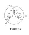
- FIG. 3 A top view of the rotary table 220 is illustrated in Figure 3 .
- the mounting system includes a plurality of mounting units 222 which are positioned symmetrically around the center of the rotary table 220.
- the rotary table 220 includes a plurality of radially extending slots 223 which allow the mounting units 222 to be fixed at different distances from the center of the rotary table 220.
- the mounting units 222 can be operated to cause fingers 225 to selectively extend from the mounting units 222 to engage and hold a cylindrical object placed on the top surface of the rotary table 220.
- the mounting units 222 can also retract the movable fingers 225 to release the cylindrical object.
- three mounting units 222 are provided on the rotary table 220. In alternate embodiments, fewer or greater numbers of the mounting units 222 could be provided.
- the mounting units 222 could be quick release mounts which include a hand operable lever that causes the finger 225 to extend or retract from the mounting units 222.
- the mounting units could be electrically, hydraulically or pneumatically operated to cause the fingers 225 to extend and retract.
- the fingers could have external screw threads that screw into threads on the body of the mounting units so that the fingers 225 can be extended and retracted. Virtually any type of manual or power operated mounting units 222 that will securely hold a cylindrical object on the top surface of the rotary table 220 could be used.
- the fixture illustrated in Figure 2 also includes a blast head movement unit 240 which is mounted at the top of the frame 210.
- the blast head movement unit 240 controls movements of a blast head 244 which sprays grit supplied from a grit supply system.
- an extension arm 242 is moveably mounted in the blast head movement unit 240.
- a grit supply pipe 243 extends down the length of the extension arm 242 to supply grit to the blast head 244.
- a coupling unit 246 is used to couple the grit supply pipe 243 to an external grit supply system hose 248.
- the supply hose 248 supplies grit from an external grit supply system.
- the extension arm 242 can be moved upward and downward in a vertical direction, as indicated by the arrows 280, by the blast head movement unit 240.
- a drive motor 249 could be used to cause selective vertical movement of the extension arm 242.
- the blast head 244 can be moved downward inside a cylindrical object so that grit sprayed from the blast head 244 will impinge upon the interior cylindrical surface of the cylindrical object.
- the blast head movement unit 240 By selectively rotating the rotary table 220 using the motor 226, and by selectively moving the blast head 244 upward and downward within the cylindrical object using the blast head movement unit 240, one can direct a stream of grit onto the entire interior cylindrical surface of the cylindrical object. Provided the movements are coordinated, it is possible to accomplish uniform sandblasting of the interior cylindrical surface.
- a controller is coupled to the blast head movement unit 240 and to the motor 226 that controls movement of the rotary table 220.
- the controller causes selective movement of the rotary table 220 and the blast head 244 to accomplish uniform sandblasting of the interior surface of the cylindrical object.
- the blast head 244 is also rotatable. This could mean rotating the blast head 244 on the extension arm 242, or rotating the extension arm 242.
- An additional rotational control unit located within the blast head movement unit 240 could be used to cause rotational movements of the blast head 244.
- the rotational control unit is used to cause oscillating movements of the blast head 244 to effect uniform sandblasting of the interior cylindrical surface of a cylindrical object.
- forklift receivers 230 are mounted on the bottom of the frame 210.
- the forklift receivers 230 are designed to receive the forks of a standard forklift so that a forklift can be used to move the fixture 200 into and out of a sandblasting facility.
- a fixture 200 as illustrated in Figure 2 can be moved into the interior of a typical blast room that includes an enclosure for performing sandblasting operations, a grit supply system capable of generating a flow of grit used for sandblasting, and a grit recovery system for recycling the grit used in sandblasting operations.
- the fixture 200 Once the fixture 200 is carried into the blast room, and a cylindrical object is mounted on the rotary table 220, the fixture 200 would be coupled to a grit supply line 248 of an external grit supply system of the blast room.
- a controller would be used to cause selective movements of the blast head 244 and the rotary table 220 to accomplish uniform sandblasting of the interior of the cylindrical object.
- the fixture 200 illustrated in Figure 2 is designed to be used in a pre-existing blast room, and it is designed to be coupled to an external grit supply unit.
- the fixture does not itself include a separate enclosure, a grit supply system or a grit recovery system.
- This means that the fixture illustrated in Figure 2 can be manufactured for far less than the cost of a self-contained sandblasting unit.
- the fixture still allows one to accomplish uniform sandblasting of the interior surface of a cylindrical object, just like one can accomplish with a more expensive self-contained sandblasting unit.
- a fixture 200 as illustrated in Figure 2 makes it possible to accomplish high quality sandblasting operations on the interior surface of a combustion liner during a repair and reconditioning process for less than it would cost to accomplish the same sandblasting operation with a traditional self-contained sandblasting unit.
- the fixture 200 illustrated in Figure 2 can lower the cost of performing the overall repair and reconditioning process.
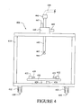
- FIG. 4 illustrates a second embodiment of a fixture 400 that can be used to conduct sandblasting operations on a cylindrical object.
- a rotary table 420 is mounted on a frame 410 by a rotary mount 424.
- a motor 426 for causing selective rotational movement of the rotary table 420 is mounted inside the frame.
- Mounting units 422 with extendable fingers 425 are provided on the top surface of the rotary table 420 to hold a cylindrical object.
- An extension arm 442 is mounted on a movement unit 440.
- a blast head 444 coupled to a grit supply pipe 443 is mounted on the extension arm 442.
- a first motor 449 is used to cause selective vertical movement of the extension arm 442 and blast head 444.
- a second motor 447 is used to cause selective rotational movement of the blast head 444.
- a coupling unit 446 is used to couple the blast head 444 to a flow of grit supplied through a grit supply line 448 of an external grit supply unit.
- a plurality of wheels 430 are mounted to the bottom surface of the frame 410 by axle units 432. This allows the fixture 400 to be easily moved into and out of an existing blast room.
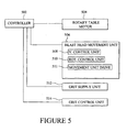
- FIG. 5 illustrates a control system that could be used to accomplish automated sandblasting operations with the fixtures illustrated in Figures 2 and 4 .
- the control system includes a controller 502 which is operatively coupled to a rotary table motor 504 that causes rotational movement of a rotary table of a fixture.
- the controller 502 is also operatively coupled to a blast head movement unit 506.
- the blast head movement unit 506 includes a vertical control unit 508.
- the blast head movement 506 also includes a rotational control unit 510 that causes rotational or oscillatory movement of the blast head.
- the controller 502 is coupled to an external grit supply unit 512.
- the external grit supply unit 512 would not be a part of the fixture, but rather would supply a flow of grit to the fixture. When connected in this fashion, the controller 502 would be able to control the flow rate and/or pressure at which grit is being supplied to the fixture by the external grit supply unit 512.
- an external grit supply unit would still be coupled to the fixture to supply a flow of grit to the fixture.
- a grit control unit 514 could be a part of the fixture itself.
- the grit control unit 514 would be capable of controlling the flow rate and/or pressure of the grit being supplied to the blast head of the fixture.
- the grit control unit 514 would also be coupled to the controller 502 so that the controller 502 can selectively vary the flow rate and/or pressure of the grit being supplied to the blast head.
- Some embodiments might have a controller coupled to both an external grit supply unit 512 and a grit control unit 514 that is part of the fixture itself.
- a fixture embodying the invention could be designed only to conduct sandblasting operations on the interior surfaces of cylindrical object. However, in alternate embodiments, the fixture may be designed to conduct sandblasting operations on both the interior and exterior surfaces of a cylindrical object. Further, a fixture embodying the invention may be designed so that the blast head can be manually or automatically moved closer to or farther away from the surfaces being sandblasted.
- FIG 6 presents a top view of the fixture illustrated in Figure 2 .
- the top wall 202 of the fixture includes a slot 204 that extends from a center of the top wall 202 towards one side edge.
- a rack gear 205 is provided along one edge of the slot 204.
- the movement unit 240, as well as the attached extension arm 242, are mounted in the slot 204. This allows the movement unit 240 and the extension arm 242 to be selectively re-positioned at different locations relative to the center of the top wall 202 of the fixture.
- the blast head 244 on the extension arm 242 can be positioned at a desired distance from the interior surface of a cylindrical objected that is mounted on the rotary table 220. This makes it easier to control the sandblasting operation.
- extension arm 242 and blast head 244 could also be positioned outside a cylindrical object that is mounted on the rotary table 220. This would allow the blast head 244 to conduct a sandblasting operation on the exterior surface of the cylindrical object.
- the movement unit 240 and the extension arm 242 could be mounted on rails that are positioned on the top of the fixture.
- the movement unit and extension arm could be movable in multiple directions, rather than in the single direction illustrated in Figure 6 .
- the movement direction could be a diagonal direction, which might allow the movement unit 240 to move farther away from the center of the fixture than the embodiment illustrated in Figure 6 .
- a controller operatively coupled to the drive unit could selectively activate the drive unit to reposition the blast head before or during sandblasting operations.
- a rack gear 205 is provided along one side edge of the slot 204.
- a pinion gear coupled to a drive motor 250 on the movement unit 240 would engage the rack gear 205.
- rotation of the pinion gear by the drive motor 250 would move the movement unit 240 along the slot to different positions with respect to the center of the frame. This would allow the blast head 244 to be selectively moved closer to and farther away from a surface of an object as the object is being sandblasted.
- a cylindrical object includes contoured surfaces or has a varying diameter, movement of the blast head in this fashion may be desirable to ensure that the blast head maintains a substantially constant distance from the surface, thereby ensuring efficient sandblasting operations.
- the control system illustrated in Figure 5 also shows that the blast head movement unit 506 includes a movement unit drive 511.
- the movement unit drive 511 which would be under the control of the controller 502, corresponds to the drive motor 250 illustrated in Figure 6 .
- the drive mechanism for moving the movement unit 240 on the frame includes a drive motor 250, a pinion gear and the rack gear 205.
- This drive mechanism is but one example of how the movement unit 240 could be selectively moved on the frame.
- an alternate drive mechanism could be used.
- the drive mechanism could be a linear motor, an arrangement of pulleys and drive belts or wires, a hydraulic or pneumatic movement mechanism, or any other sort of drive mechanism, as is well known to those of ordinary skill in the art.
- the controller 502 illustrated in Figure 5 could be provided as part of the fixture. In other instances, the controller could be a separate external controller that is coupled to the various drive mechanisms and control units of the fixture.
Description
- Gas turbines used in the electrical power generation industry include combustors which bum an air-fuel mixture. The expanding gases are then routed into the turbine section to generative motive force. The combustors typically include a
cylindrical combustion liner 100, as shown inFigure 1 . The combustion of the air-fuel mixture occurs inside the cylindrical combustion liner. - After a
combustion liner 100 has been used in a gas turbine for an extended period of time, it is necessary to repair and recondition thecombustion liner 100. Part of the repair and reconditioning process involves sandblasting the interior cylindrical surface of the combustion liner to remove any buildup of combustion byproducts. - One way to accomplish sandblasting of the interior cylindrical surface is to place the combustion liner in a blast room, and then manually direct a flow of grit along the interior cylindrical surface of the combustion liner to remove contaminants. An operator typically holds a hose that supplies a flow of grit delivered under pressure, and the operator directs the flow of grit onto the interior cylindrical surface of the
combustion liner 100. Unfortunately, it is very difficult for an operator to evenly or uniformly sandblast the entire interior cylindrical surface. - Another option is to purchase a self-contained sandblasting unit which is designed to automatically sandblast such objects. A self-contained sandblasting unit typically includes an enclosure, a mounting system for mounting a cylindrical object inside the enclosure, a grit supply and recovery system, and a movable blast head which can be programmed to move in an automated fashion. The blast head moves automatically under the direction of a processor to direct a flow of grit along the interior cylindrical surface of a combustion liner to remove any contaminants.
- Although a self-contained sandblasting unit can conduct a more uniform sandblasting operation on the interior of a cylindrical combustion liner than a manual sandblasting operation, these self-contained sandblasting units are relatively expensive. For this reason, many in the industry prefer to manually sandblast combustion liners, even though it will result in less uniform results. A method and apparatus for milling objects by means of a high velocity water jet is disclosed in
US 5704824 . The document describes apparatus for holding and producing relative motion in three dimensions of both the object and the water jet. - The invention provides a fixture that facilitates sandblasting of a generally cylindrical object, comprising: a frame; a rotary table mounted on the frame, the rotary table comprising a mounting system that is operable to securely hold a generally cylindrical object and being configured to selectively rotate the cylindrical object; the mounting system comprising a plurality of mounting units that are operable to clamp a generally cylindrical object between the plurality of mounting units the mounting units including fmgers operable to selectively extend from the mounting unit to engage and hold the object; a blast head movement unit mounted on the frame; and a blast head mounted on the blast head movement unit, wherein the blast head movement unit is configured to move the blast head in a vertical direction, a rotational direction and to oscillate, and wherein the blast head is configured to be attached to a grit supply system.
-
-
Figure 1 is a perspective view of a cylindrical combustion liner of a gas turbine; -
Figure 2 is a diagram of a fixture which facilitates sandblasting of a generally cylindrical object; -
Figure 3 is a top view of a rotary table which can be used in a fixture as illustrated inFigure 2 ; -
Figure 4 is a diagram of a second embodiment of a fixture that facilitates sandblasting of a generally cylindrical object; -
Figure 5 is a diagram illustrating the major elements of a control system for a fixture as illustrated inFigures 2 and4 ; and -
Figure 6 is a top view of a fixture that facilitates sandblasting of a cylindrical object. - In the following description, references are made to "sandblasting." This term is intended to encompass any procedures where a flow of abrasive particles are used to remove contaminants or surface coatings. While sand was traditionally used for this purpose, other abrasive materials can also be used. For example, the blast media could also be aluminum oxide, silicon carbide, garnet, fruit stones, walnut shells, rice hulls, dry ice pellets, or a variety of other media, as is well known to those of ordinary skill in the art.
-
Figure 2 illustrates a first embodiment of a fixture which facilitates sandblasting of an internal wall of a generally cylindrical object. Thefixture 200 includes aframe 210. A rotary table 220 is rotationally mounted on theframe 210 by arotational mount 224. A mounting system on the top surface of the rotary table 220 is used to mount a generally cylindrical object onto the top surface of the rotary table 220. Amotor 226 can cause the rotary table 220 to selectively rotate. - A top view of the rotary table 220 is illustrated in
Figure 3 . As shown inFigures 2 and3 , the mounting system includes a plurality ofmounting units 222 which are positioned symmetrically around the center of the rotary table 220. The rotary table 220 includes a plurality of radially extendingslots 223 which allow themounting units 222 to be fixed at different distances from the center of the rotary table 220. Once themounting units 222 are fixed in place, themounting units 222 can be operated to causefingers 225 to selectively extend from themounting units 222 to engage and hold a cylindrical object placed on the top surface of the rotary table 220. Themounting units 222 can also retract themovable fingers 225 to release the cylindrical object. - In the embodiment illustrated in
Figure 3 , threemounting units 222 are provided on the rotary table 220. In alternate embodiments, fewer or greater numbers of themounting units 222 could be provided. - In some embodiments, the
mounting units 222 could be quick release mounts which include a hand operable lever that causes thefinger 225 to extend or retract from themounting units 222. In other embodiments, the mounting units could be electrically, hydraulically or pneumatically operated to cause thefingers 225 to extend and retract. In still other embodiments, the fingers could have external screw threads that screw into threads on the body of the mounting units so that thefingers 225 can be extended and retracted. Virtually any type of manual or power operatedmounting units 222 that will securely hold a cylindrical object on the top surface of the rotary table 220 could be used. - The fixture illustrated in
Figure 2 also includes a blasthead movement unit 240 which is mounted at the top of theframe 210. The blasthead movement unit 240 controls movements of ablast head 244 which sprays grit supplied from a grit supply system. In this embodiment, anextension arm 242 is moveably mounted in the blasthead movement unit 240. Agrit supply pipe 243 extends down the length of theextension arm 242 to supply grit to theblast head 244. - At the upper end of the extension arm 242 a
coupling unit 246 is used to couple thegrit supply pipe 243 to an external gritsupply system hose 248. Thesupply hose 248 supplies grit from an external grit supply system. - The
extension arm 242 can be moved upward and downward in a vertical direction, as indicated by thearrows 280, by the blasthead movement unit 240. Adrive motor 249 could be used to cause selective vertical movement of theextension arm 242. - Once a cylindrical object such as the
combustor liner 100 illustrated inFigure 1 has been clamped onto the rotary table 220, theblast head 244 can be moved downward inside a cylindrical object so that grit sprayed from theblast head 244 will impinge upon the interior cylindrical surface of the cylindrical object. By selectively rotating the rotary table 220 using themotor 226, and by selectively moving theblast head 244 upward and downward within the cylindrical object using the blasthead movement unit 240, one can direct a stream of grit onto the entire interior cylindrical surface of the cylindrical object. Provided the movements are coordinated, it is possible to accomplish uniform sandblasting of the interior cylindrical surface. - In preferred embodiments, a controller is coupled to the blast
head movement unit 240 and to themotor 226 that controls movement of the rotary table 220. The controller causes selective movement of the rotary table 220 and theblast head 244 to accomplish uniform sandblasting of the interior surface of the cylindrical object. - The
blast head 244 is also rotatable. This could mean rotating theblast head 244 on theextension arm 242, or rotating theextension arm 242. An additional rotational control unit located within the blasthead movement unit 240 could be used to cause rotational movements of theblast head 244. The rotational control unit is used to cause oscillating movements of theblast head 244 to effect uniform sandblasting of the interior cylindrical surface of a cylindrical object. - In the embodiment illustrated in
Figure 2 ,forklift receivers 230 are mounted on the bottom of theframe 210. Theforklift receivers 230 are designed to receive the forks of a standard forklift so that a forklift can be used to move thefixture 200 into and out of a sandblasting facility. - A
fixture 200 as illustrated inFigure 2 can be moved into the interior of a typical blast room that includes an enclosure for performing sandblasting operations, a grit supply system capable of generating a flow of grit used for sandblasting, and a grit recovery system for recycling the grit used in sandblasting operations. Once thefixture 200 is carried into the blast room, and a cylindrical object is mounted on the rotary table 220, thefixture 200 would be coupled to agrit supply line 248 of an external grit supply system of the blast room. A controller would be used to cause selective movements of theblast head 244 and the rotary table 220 to accomplish uniform sandblasting of the interior of the cylindrical object. - The
fixture 200 illustrated inFigure 2 is designed to be used in a pre-existing blast room, and it is designed to be coupled to an external grit supply unit. Thus, the fixture does not itself include a separate enclosure, a grit supply system or a grit recovery system. This means that the fixture illustrated inFigure 2 can be manufactured for far less than the cost of a self-contained sandblasting unit. However, the fixture still allows one to accomplish uniform sandblasting of the interior surface of a cylindrical object, just like one can accomplish with a more expensive self-contained sandblasting unit. - A
fixture 200 as illustrated inFigure 2 makes it possible to accomplish high quality sandblasting operations on the interior surface of a combustion liner during a repair and reconditioning process for less than it would cost to accomplish the same sandblasting operation with a traditional self-contained sandblasting unit. Thus, thefixture 200 illustrated inFigure 2 can lower the cost of performing the overall repair and reconditioning process. -
Figure 4 illustrates a second embodiment of afixture 400 that can be used to conduct sandblasting operations on a cylindrical object. In this embodiment, a rotary table 420 is mounted on aframe 410 by arotary mount 424. However, in this embodiment, amotor 426 for causing selective rotational movement of the rotary table 420 is mounted inside the frame. Mountingunits 422 withextendable fingers 425 are provided on the top surface of the rotary table 420 to hold a cylindrical object. - An
extension arm 442 is mounted on amovement unit 440. Ablast head 444 coupled to agrit supply pipe 443 is mounted on theextension arm 442. Afirst motor 449 is used to cause selective vertical movement of theextension arm 442 andblast head 444. Asecond motor 447 is used to cause selective rotational movement of theblast head 444. Acoupling unit 446 is used to couple theblast head 444 to a flow of grit supplied through agrit supply line 448 of an external grit supply unit. - In this embodiment a plurality of
wheels 430 are mounted to the bottom surface of theframe 410 byaxle units 432. This allows thefixture 400 to be easily moved into and out of an existing blast room. -
Figure 5 illustrates a control system that could be used to accomplish automated sandblasting operations with the fixtures illustrated inFigures 2 and4 . The control system includes acontroller 502 which is operatively coupled to arotary table motor 504 that causes rotational movement of a rotary table of a fixture. Thecontroller 502 is also operatively coupled to a blasthead movement unit 506. The blasthead movement unit 506 includes avertical control unit 508. Theblast head movement 506 also includes arotational control unit 510 that causes rotational or oscillatory movement of the blast head. - In some embodiments, the
controller 502 is coupled to an externalgrit supply unit 512. The externalgrit supply unit 512 would not be a part of the fixture, but rather would supply a flow of grit to the fixture. When connected in this fashion, thecontroller 502 would be able to control the flow rate and/or pressure at which grit is being supplied to the fixture by the externalgrit supply unit 512. - In other embodiments, an external grit supply unit would still be coupled to the fixture to supply a flow of grit to the fixture. However, a
grit control unit 514 could be a part of the fixture itself. Thegrit control unit 514 would be capable of controlling the flow rate and/or pressure of the grit being supplied to the blast head of the fixture. Thegrit control unit 514 would also be coupled to thecontroller 502 so that thecontroller 502 can selectively vary the flow rate and/or pressure of the grit being supplied to the blast head. - Some embodiments might have a controller coupled to both an external
grit supply unit 512 and agrit control unit 514 that is part of the fixture itself. - A fixture embodying the invention could be designed only to conduct sandblasting operations on the interior surfaces of cylindrical object. However, in alternate embodiments, the fixture may be designed to conduct sandblasting operations on both the interior and exterior surfaces of a cylindrical object. Further, a fixture embodying the invention may be designed so that the blast head can be manually or automatically moved closer to or farther away from the surfaces being sandblasted.
-
Figure 6 presents a top view of the fixture illustrated inFigure 2 . Thetop wall 202 of the fixture includes aslot 204 that extends from a center of thetop wall 202 towards one side edge. In this embodiment, arack gear 205 is provided along one edge of theslot 204. - The
movement unit 240, as well as the attachedextension arm 242, are mounted in theslot 204. This allows themovement unit 240 and theextension arm 242 to be selectively re-positioned at different locations relative to the center of thetop wall 202 of the fixture. - When a fixture is configured as illustrated in
Figures 2 and6 , theblast head 244 on theextension arm 242 can be positioned at a desired distance from the interior surface of a cylindrical objected that is mounted on the rotary table 220. This makes it easier to control the sandblasting operation. - In addition, the
extension arm 242 andblast head 244 could also be positioned outside a cylindrical object that is mounted on the rotary table 220. This would allow theblast head 244 to conduct a sandblasting operation on the exterior surface of the cylindrical object. - The arrangement illustrated in
Figure 6 is only one example. In other embodiments, themovement unit 240 and theextension arm 242 could be mounted on rails that are positioned on the top of the fixture. Also, the movement unit and extension arm could be movable in multiple directions, rather than in the single direction illustrated inFigure 6 . Further, the movement direction could be a diagonal direction, which might allow themovement unit 240 to move farther away from the center of the fixture than the embodiment illustrated inFigure 6 . - If the
movement unit 240 includes a drive unit, a controller operatively coupled to the drive unit could selectively activate the drive unit to reposition the blast head before or during sandblasting operations. In the embodiment illustrated inFigure 6 , arack gear 205 is provided along one side edge of theslot 204. A pinion gear coupled to adrive motor 250 on themovement unit 240 would engage therack gear 205. Thus, rotation of the pinion gear by thedrive motor 250 would move themovement unit 240 along the slot to different positions with respect to the center of the frame. This would allow theblast head 244 to be selectively moved closer to and farther away from a surface of an object as the object is being sandblasted. If a cylindrical object includes contoured surfaces or has a varying diameter, movement of the blast head in this fashion may be desirable to ensure that the blast head maintains a substantially constant distance from the surface, thereby ensuring efficient sandblasting operations. - The control system illustrated in
Figure 5 also shows that the blasthead movement unit 506 includes amovement unit drive 511. Themovement unit drive 511, which would be under the control of thecontroller 502, corresponds to thedrive motor 250 illustrated inFigure 6 . - The drive mechanism for moving the
movement unit 240 on the frame, as illustrated inFigure 6 , includes adrive motor 250, a pinion gear and therack gear 205. This drive mechanism is but one example of how themovement unit 240 could be selectively moved on the frame. In other embodiments, an alternate drive mechanism could be used. For example, the drive mechanism could be a linear motor, an arrangement of pulleys and drive belts or wires, a hydraulic or pneumatic movement mechanism, or any other sort of drive mechanism, as is well known to those of ordinary skill in the art. - The
controller 502 illustrated inFigure 5 could be provided as part of the fixture. In other instances, the controller could be a separate external controller that is coupled to the various drive mechanisms and control units of the fixture. - The scope of the invention is defined in the appended claims.
Claims (9)
- A fixture (200, 400) that facilitates sandblasting of a generally cylindrical object (106), comprising:a frame (210, 410);a rotary table (220, 420) mounted on the frame, the rotary table comprising a mounting system (222,422) that is operable to securely hold a generally cylindrical object (100) and being configured to selectively rotate the cylindrical object;the mounting system comprising a plurality of mounting units that are operable to clamp a generally cylindrical object between the plurality of mounting units the mounting units including fingers (225,425) operable to selectively extend from the mounting unit to engage and hold the object;a blast head movement unit (240, 440, 506) mounted on the frame; anda blast head (244, 444) mounted on the blast head movement unit, wherein the blast head movement unit is configured to move the blast head in a vertical direction (280), a rotational direction and to oscillate, and wherein the blast head is configured to be attached to a grit supply system (512).
- The fixture (200, 400) of claim 1, further comprising a controller (502) that is coupled to the rotary table (220, 420) and the blast head movement unit (240, 440, 506), the controller operable to send signals to the rotary table to cause the rotary table to selectively rotate, the controller also operable to send signals to the blast head movement unit to cause the blast head to selectively move in at least one direction.
- The fixture (200, 400) of claim 2, wherein the controller (502) is also configured to send signals to an external grit supply system (512) to control a flow of grit supplied by the grit supply system.
- The fixture (200, 400) of either of claim 2 or 3, further comprising a grit control unit (514) that controls a flow of grit that is sprayed from the blast head (244, 444), wherein the controller (502) is coupled to the grit control unit, and wherein the controller is operable to send signals to the grit control unit that cause the grit control unit to selectively vary the flow of grit that is sprayed from the blast head.
- The fixture (200, 400) of claim 1, further comprising a grit control unit (514) that controls a flow of grit that is sprayed from the blast head (224, 444).
- The fixture (200, 400) of claim 1, wherein the mounting units (222, 422) are mounted in slots (223) that extend in a radial direction relative to a center of the rotary table (220, 420) such that the mounting units can be selectively positioned at a plurality of different positions relative to the center of the rotary table.
- The fixture (200, 400) of claim 1, wherein the rotary table (220, 420) includes a motor (226, 426) that is configured to selectively rotate the rotary table on the fixture.
- The fixture (200, 400) of claim 1, wherein the blast head movement unit (240, 440, 506) is movably mounted on the frame (210, 410) so that it can be selectively repositioned on the frame.
- The fixture (200, 400) of claim 8, further comprising a drive unit (249, 447, 449) that is configured to selectively move the blast head (244, 444) relative to the frame (210, 410).
Applications Claiming Priority (1)
| Application Number | Priority Date | Filing Date | Title |
|---|---|---|---|
| US13/218,040 US8506361B2 (en) | 2011-08-25 | 2011-08-25 | Fixture to facilitate sandblasting of a cylindrical object |
Publications (2)
| Publication Number | Publication Date |
|---|---|
| EP2561960A1 EP2561960A1 (en) | 2013-02-27 |
| EP2561960B1 true EP2561960B1 (en) | 2015-03-18 |
Family
ID=46724270
Family Applications (1)
| Application Number | Title | Priority Date | Filing Date |
|---|---|---|---|
| EP12181230.9A Not-in-force EP2561960B1 (en) | 2011-08-25 | 2012-08-21 | Fixture to facilitate sandblasting of a cylindrical object |
Country Status (4)
| Country | Link |
|---|---|
| US (1) | US8506361B2 (en) |
| EP (1) | EP2561960B1 (en) |
| JP (1) | JP2013043281A (en) |
| CN (1) | CN102975126B (en) |
Cited By (1)
| Publication number | Priority date | Publication date | Assignee | Title |
|---|---|---|---|---|
| CN106985077A (en) * | 2017-03-27 | 2017-07-28 | 宁波工程学院 | A kind of surface-strengthening equipment and method based on jet |
Families Citing this family (10)
| Publication number | Priority date | Publication date | Assignee | Title |
|---|---|---|---|---|
| CN103231085A (en) * | 2013-05-09 | 2013-08-07 | 吴江市董鑫塑料包装厂 | Lathe fixture |
| WO2015025346A1 (en) * | 2013-08-19 | 2015-02-26 | 株式会社日立製作所 | Plating stripping device |
| CN103447966A (en) * | 2013-08-28 | 2013-12-18 | 珠海醇逸嘉华包装材料科技有限公司 | Method and device for automatically and mechanically sanding and carving on internal surface of glassware |
| CN105215858A (en) * | 2015-10-15 | 2016-01-06 | 鹤山市精工制版有限公司 | A kind of grinding, sand blasting integrated machine |
| CN106346371B (en) * | 2016-08-30 | 2018-07-06 | 来安县科来兴实业有限责任公司 | A kind of multi-functional full-automatic mold sand blasting unit |
| DE102019111723A1 (en) | 2019-05-06 | 2020-11-12 | Hauhinco Maschinenfabrik G. Hausherr, Jochums Gmbh & Co. Kg | Workpiece drive and descaling device with workpiece drive |
| CN110524432A (en) * | 2019-09-06 | 2019-12-03 | 宁波大学 | Sandblasting mechanism |
| CN113681473B (en) * | 2021-08-23 | 2022-09-06 | 连云港品鑫压力容器制造有限公司 | Inner wall rust removing device for pressure vessel processing |
| CN114102448A (en) * | 2021-11-30 | 2022-03-01 | 堃昊电子科技(江苏)有限公司 | Surface sand blasting device for communication piece of 5G base station |
| CN116639468B (en) * | 2023-05-08 | 2023-12-08 | 株洲扬光新材料有限公司 | Metal surface sand blasting equipment and process |
Citations (2)
| Publication number | Priority date | Publication date | Assignee | Title |
|---|---|---|---|---|
| EP1068919A1 (en) * | 1999-07-14 | 2001-01-17 | Erowa AG | Device to clamp a workpiece in a definite position in a working area of a machine tool |
| EP2433734A1 (en) * | 2010-09-27 | 2012-03-28 | MAG IAS GmbH | Milling machine for producing gears |
Family Cites Families (26)
| Publication number | Priority date | Publication date | Assignee | Title |
|---|---|---|---|---|
| US2394376A (en) * | 1945-05-31 | 1946-02-05 | Frank S Grylewicz | Work holder |
| US3041787A (en) * | 1959-10-21 | 1962-07-03 | Bell Intercontinental Corp | Blasting machine |
| US3604157A (en) * | 1969-04-10 | 1971-09-14 | Wheelabrator Corp | Blast machine with automatic blast wheel positioner |
| US3672292A (en) | 1970-09-22 | 1972-06-27 | Vacu Blast Corp | Blast-room for abrasive blasting system |
| CA1321478C (en) * | 1989-05-30 | 1993-08-24 | Somyong Visaisouk | Particle blast cleaning and treating of surfaces |
| US5209028A (en) * | 1992-04-15 | 1993-05-11 | Air Products And Chemicals, Inc. | Apparatus to clean solid surfaces using a cryogenic aerosol |
| US5704824A (en) | 1993-10-12 | 1998-01-06 | Hashish; Mohamad | Method and apparatus for abrasive water jet millins |
| US5411244A (en) * | 1994-03-04 | 1995-05-02 | Turner; Tommy P. | Clamp using elastic tension member |
| DE4440631C2 (en) * | 1994-11-14 | 1998-07-09 | Trumpf Gmbh & Co | Method and processing machine for beam cutting workpieces using at least two cutting beams |
| US5709587A (en) * | 1996-03-25 | 1998-01-20 | Kennametal Inc. | Method and apparatus for honing an elongate rotary tool |
| CA2262688A1 (en) * | 1996-08-22 | 1998-02-26 | David Alan Whitney | Robotic co2 tire mold cleaning |
| JPH1133916A (en) * | 1997-07-16 | 1999-02-09 | Pipe Giken:Kk | Grinding system, and grinding device to be used for this system |
| JP3674306B2 (en) * | 1998-05-08 | 2005-07-20 | スズキ株式会社 | Cylinder inner surface blasting method |
| EP0960950A1 (en) | 1998-05-27 | 1999-12-01 | Waterjet Technology, Inc. | Method and apparatus for ultrahigh pressure water jet peening |
| US6244927B1 (en) * | 1998-08-31 | 2001-06-12 | Ingersoll-Rand Company | Multi-functional sensing methods and apparatus therefor |
| JP2000225528A (en) * | 1999-02-05 | 2000-08-15 | Ishikawajima Harima Heavy Ind Co Ltd | High pressure water jetting device |
| US6568994B1 (en) * | 1999-08-24 | 2003-05-27 | General Electric Company | Shifting edge scrubbing |
| CA2383082A1 (en) * | 1999-09-01 | 2001-03-08 | Siemens Aktiengesellschaft | Method and device for the surface threatment of a component |
| US6520838B1 (en) * | 2001-06-25 | 2003-02-18 | General Electric Company | Shielded spin polishing |
| JP3896265B2 (en) * | 2001-09-11 | 2007-03-22 | オリンパス株式会社 | Positioning jig and spray polishing apparatus using positioning jig |
| JP2003117829A (en) * | 2001-10-03 | 2003-04-23 | Sunrise Kogyo Kk | Quartz oscillator, quartz filter, and device and method for manufacturing the quartz oscillator |
| JP2003214427A (en) * | 2002-01-21 | 2003-07-30 | Minebea Co Ltd | Cleaning method and cleaning device for fluid dynamic pressure bearing |
| CN2609715Y (en) * | 2003-05-16 | 2004-04-07 | 高侨自动化科技股份有限公司 | Wafer sand ejector |
| US8187056B2 (en) * | 2006-12-14 | 2012-05-29 | Flow International Corporation | Process and apparatus for surface-finishing |
| US20090189312A1 (en) * | 2008-01-24 | 2009-07-30 | Whip Mix Corporation | Device and method for removing investment from a dental appliance |
| JP2010274354A (en) | 2009-05-27 | 2010-12-09 | Yokohama Rubber Co Ltd:The | Wet blast washing device and method |
-
2011
- 2011-08-25 US US13/218,040 patent/US8506361B2/en active Active
-
2012
- 2012-08-17 JP JP2012180695A patent/JP2013043281A/en active Pending
- 2012-08-21 EP EP12181230.9A patent/EP2561960B1/en not_active Not-in-force
- 2012-08-24 CN CN201210304445.XA patent/CN102975126B/en not_active Expired - Fee Related
Patent Citations (2)
| Publication number | Priority date | Publication date | Assignee | Title |
|---|---|---|---|---|
| EP1068919A1 (en) * | 1999-07-14 | 2001-01-17 | Erowa AG | Device to clamp a workpiece in a definite position in a working area of a machine tool |
| EP2433734A1 (en) * | 2010-09-27 | 2012-03-28 | MAG IAS GmbH | Milling machine for producing gears |
Cited By (2)
| Publication number | Priority date | Publication date | Assignee | Title |
|---|---|---|---|---|
| CN106985077A (en) * | 2017-03-27 | 2017-07-28 | 宁波工程学院 | A kind of surface-strengthening equipment and method based on jet |
| CN106985077B (en) * | 2017-03-27 | 2019-09-06 | 宁波工程学院 | A kind of surface-strengthening equipment and method based on jet stream |
Also Published As
| Publication number | Publication date |
|---|---|
| CN102975126B (en) | 2017-03-01 |
| JP2013043281A (en) | 2013-03-04 |
| EP2561960A1 (en) | 2013-02-27 |
| US8506361B2 (en) | 2013-08-13 |
| CN102975126A (en) | 2013-03-20 |
| US20130052920A1 (en) | 2013-02-28 |
Similar Documents
| Publication | Publication Date | Title |
|---|---|---|
| EP2561960B1 (en) | Fixture to facilitate sandblasting of a cylindrical object | |
| CN206357058U (en) | A kind of floating sanding apparatus | |
| CN102001046B (en) | Rotary table type automatic sand-blasting machine | |
| CN101338359A (en) | Pneumatic numerical control shot blasting strengthen machine | |
| CN103861754A (en) | Mobile slender workpiece sand blasting and electric arc spraying device capable of realizing automatic recovery and circulation of sand | |
| CN107234501B (en) | A kind of full-automatic scraper grinder with cleaning plant | |
| WO2013172917A1 (en) | Fluid jet receptacle with rotatable inlet feed component and related fluid jet cutting system and method | |
| CN212330722U (en) | Sand blasting and rust removing device for surface of machined part | |
| CN212735641U (en) | Shot blasting machine with workpiece clamping function | |
| CN110587427A (en) | Polishing equipment with heat dissipation function for titanium alloy | |
| US6699109B1 (en) | Apparatus and method of removing abradable material from a turbomachine fan containment case | |
| CN117103139A (en) | Multifunctional spraying device for sand blasting machine | |
| CN215968265U (en) | Sand blasting rust removal device for steel structure construction | |
| CN210998217U (en) | Sand blasting machine with uniform sand blasting | |
| US20220097208A1 (en) | Abrasive blast treatment machine for surfaces of large-scale workpieces | |
| JP2006035347A (en) | Polishing device and polishing method | |
| JP2007105818A (en) | Method and apparatus for internally machining cylinder liner | |
| CN112476149A (en) | Workpiece batch processing equipment with strong cooling performance | |
| CN205765671U (en) | A kind of can the comprehensive sandblasting machine of quick feeding | |
| CN216657616U (en) | Metal structure processing grinding device | |
| CN211278025U (en) | Sand blasting equipment for machining motorcycle accessories | |
| CN215037537U (en) | Outdoor sandblast machine people | |
| CN113843717B (en) | Quick polishing device and method for thermal spraying hard coating | |
| CN218534154U (en) | Carbide blade flank of tooth sand blasting equipment | |
| CN115157126B (en) | Auto-parts is with automatic sand blasting unit |
Legal Events
| Date | Code | Title | Description |
|---|---|---|---|
| PUAI | Public reference made under article 153(3) epc to a published international application that has entered the european phase |
Free format text: ORIGINAL CODE: 0009012 |
|
| AK | Designated contracting states |
Kind code of ref document: A1 Designated state(s): AL AT BE BG CH CY CZ DE DK EE ES FI FR GB GR HR HU IE IS IT LI LT LU LV MC MK MT NL NO PL PT RO RS SE SI SK SM TR |
|
| AX | Request for extension of the european patent |
Extension state: BA ME |
|
| 17P | Request for examination filed |
Effective date: 20130827 |
|
| RBV | Designated contracting states (corrected) |
Designated state(s): AL AT BE BG CH CY CZ DE DK EE ES FI FR GB GR HR HU IE IS IT LI LT LU LV MC MK MT NL NO PL PT RO RS SE SI SK SM TR |
|
| 17Q | First examination report despatched |
Effective date: 20131119 |
|
| GRAP | Despatch of communication of intention to grant a patent |
Free format text: ORIGINAL CODE: EPIDOSNIGR1 |
|
| INTG | Intention to grant announced |
Effective date: 20141110 |
|
| GRAS | Grant fee paid |
Free format text: ORIGINAL CODE: EPIDOSNIGR3 |
|
| GRAA | (expected) grant |
Free format text: ORIGINAL CODE: 0009210 |
|
| AK | Designated contracting states |
Kind code of ref document: B1 Designated state(s): AL AT BE BG CH CY CZ DE DK EE ES FI FR GB GR HR HU IE IS IT LI LT LU LV MC MK MT NL NO PL PT RO RS SE SI SK SM TR |
|
| REG | Reference to a national code |
Ref country code: GB Ref legal event code: FG4D |
|
| REG | Reference to a national code |
Ref country code: CH Ref legal event code: EP |
|
| REG | Reference to a national code |
Ref country code: IE Ref legal event code: FG4D |
|
| REG | Reference to a national code |
Ref country code: AT Ref legal event code: REF Ref document number: 716242 Country of ref document: AT Kind code of ref document: T Effective date: 20150415 |
|
| REG | Reference to a national code |
Ref country code: DE Ref legal event code: R096 Ref document number: 602012005937 Country of ref document: DE Effective date: 20150430 |
|
| REG | Reference to a national code |
Ref country code: NL Ref legal event code: VDEP Effective date: 20150318 |
|
| REG | Reference to a national code |
Ref country code: NL Ref legal event code: VDEP Effective date: 20150318 |
|
| PG25 | Lapsed in a contracting state [announced via postgrant information from national office to epo] |
Ref country code: SE Free format text: LAPSE BECAUSE OF FAILURE TO SUBMIT A TRANSLATION OF THE DESCRIPTION OR TO PAY THE FEE WITHIN THE PRESCRIBED TIME-LIMIT Effective date: 20150318 Ref country code: LT Free format text: LAPSE BECAUSE OF FAILURE TO SUBMIT A TRANSLATION OF THE DESCRIPTION OR TO PAY THE FEE WITHIN THE PRESCRIBED TIME-LIMIT Effective date: 20150318 Ref country code: HR Free format text: LAPSE BECAUSE OF FAILURE TO SUBMIT A TRANSLATION OF THE DESCRIPTION OR TO PAY THE FEE WITHIN THE PRESCRIBED TIME-LIMIT Effective date: 20150318 Ref country code: FI Free format text: LAPSE BECAUSE OF FAILURE TO SUBMIT A TRANSLATION OF THE DESCRIPTION OR TO PAY THE FEE WITHIN THE PRESCRIBED TIME-LIMIT Effective date: 20150318 Ref country code: NO Free format text: LAPSE BECAUSE OF FAILURE TO SUBMIT A TRANSLATION OF THE DESCRIPTION OR TO PAY THE FEE WITHIN THE PRESCRIBED TIME-LIMIT Effective date: 20150618 |
|
| REG | Reference to a national code |
Ref country code: AT Ref legal event code: MK05 Ref document number: 716242 Country of ref document: AT Kind code of ref document: T Effective date: 20150318 |
|
| REG | Reference to a national code |
Ref country code: LT Ref legal event code: MG4D |
|
| PG25 | Lapsed in a contracting state [announced via postgrant information from national office to epo] |
Ref country code: GR Free format text: LAPSE BECAUSE OF FAILURE TO SUBMIT A TRANSLATION OF THE DESCRIPTION OR TO PAY THE FEE WITHIN THE PRESCRIBED TIME-LIMIT Effective date: 20150619 Ref country code: LV Free format text: LAPSE BECAUSE OF FAILURE TO SUBMIT A TRANSLATION OF THE DESCRIPTION OR TO PAY THE FEE WITHIN THE PRESCRIBED TIME-LIMIT Effective date: 20150318 Ref country code: RS Free format text: LAPSE BECAUSE OF FAILURE TO SUBMIT A TRANSLATION OF THE DESCRIPTION OR TO PAY THE FEE WITHIN THE PRESCRIBED TIME-LIMIT Effective date: 20150318 |
|
| PG25 | Lapsed in a contracting state [announced via postgrant information from national office to epo] |
Ref country code: NL Free format text: LAPSE BECAUSE OF FAILURE TO SUBMIT A TRANSLATION OF THE DESCRIPTION OR TO PAY THE FEE WITHIN THE PRESCRIBED TIME-LIMIT Effective date: 20150318 |
|
| PG25 | Lapsed in a contracting state [announced via postgrant information from national office to epo] |
Ref country code: RO Free format text: LAPSE BECAUSE OF FAILURE TO SUBMIT A TRANSLATION OF THE DESCRIPTION OR TO PAY THE FEE WITHIN THE PRESCRIBED TIME-LIMIT Effective date: 20150318 Ref country code: EE Free format text: LAPSE BECAUSE OF FAILURE TO SUBMIT A TRANSLATION OF THE DESCRIPTION OR TO PAY THE FEE WITHIN THE PRESCRIBED TIME-LIMIT Effective date: 20150318 Ref country code: ES Free format text: LAPSE BECAUSE OF FAILURE TO SUBMIT A TRANSLATION OF THE DESCRIPTION OR TO PAY THE FEE WITHIN THE PRESCRIBED TIME-LIMIT Effective date: 20150318 Ref country code: SK Free format text: LAPSE BECAUSE OF FAILURE TO SUBMIT A TRANSLATION OF THE DESCRIPTION OR TO PAY THE FEE WITHIN THE PRESCRIBED TIME-LIMIT Effective date: 20150318 Ref country code: PT Free format text: LAPSE BECAUSE OF FAILURE TO SUBMIT A TRANSLATION OF THE DESCRIPTION OR TO PAY THE FEE WITHIN THE PRESCRIBED TIME-LIMIT Effective date: 20150720 Ref country code: CZ Free format text: LAPSE BECAUSE OF FAILURE TO SUBMIT A TRANSLATION OF THE DESCRIPTION OR TO PAY THE FEE WITHIN THE PRESCRIBED TIME-LIMIT Effective date: 20150318 |
|
| PG25 | Lapsed in a contracting state [announced via postgrant information from national office to epo] |
Ref country code: AT Free format text: LAPSE BECAUSE OF FAILURE TO SUBMIT A TRANSLATION OF THE DESCRIPTION OR TO PAY THE FEE WITHIN THE PRESCRIBED TIME-LIMIT Effective date: 20150318 Ref country code: PL Free format text: LAPSE BECAUSE OF FAILURE TO SUBMIT A TRANSLATION OF THE DESCRIPTION OR TO PAY THE FEE WITHIN THE PRESCRIBED TIME-LIMIT Effective date: 20150318 Ref country code: IS Free format text: LAPSE BECAUSE OF FAILURE TO SUBMIT A TRANSLATION OF THE DESCRIPTION OR TO PAY THE FEE WITHIN THE PRESCRIBED TIME-LIMIT Effective date: 20150718 |
|
| REG | Reference to a national code |
Ref country code: DE Ref legal event code: R097 Ref document number: 602012005937 Country of ref document: DE |
|
| PG25 | Lapsed in a contracting state [announced via postgrant information from national office to epo] |
Ref country code: IT Free format text: LAPSE BECAUSE OF FAILURE TO SUBMIT A TRANSLATION OF THE DESCRIPTION OR TO PAY THE FEE WITHIN THE PRESCRIBED TIME-LIMIT Effective date: 20150318 |
|
| PLBE | No opposition filed within time limit |
Free format text: ORIGINAL CODE: 0009261 |
|
| STAA | Information on the status of an ep patent application or granted ep patent |
Free format text: STATUS: NO OPPOSITION FILED WITHIN TIME LIMIT |
|
| PG25 | Lapsed in a contracting state [announced via postgrant information from national office to epo] |
Ref country code: DK Free format text: LAPSE BECAUSE OF FAILURE TO SUBMIT A TRANSLATION OF THE DESCRIPTION OR TO PAY THE FEE WITHIN THE PRESCRIBED TIME-LIMIT Effective date: 20150318 |
|
| 26N | No opposition filed |
Effective date: 20151221 |
|
| PG25 | Lapsed in a contracting state [announced via postgrant information from national office to epo] |
Ref country code: SI Free format text: LAPSE BECAUSE OF FAILURE TO SUBMIT A TRANSLATION OF THE DESCRIPTION OR TO PAY THE FEE WITHIN THE PRESCRIBED TIME-LIMIT Effective date: 20150318 |
|
| PG25 | Lapsed in a contracting state [announced via postgrant information from national office to epo] |
Ref country code: LU Free format text: LAPSE BECAUSE OF FAILURE TO SUBMIT A TRANSLATION OF THE DESCRIPTION OR TO PAY THE FEE WITHIN THE PRESCRIBED TIME-LIMIT Effective date: 20150821 Ref country code: MC Free format text: LAPSE BECAUSE OF FAILURE TO SUBMIT A TRANSLATION OF THE DESCRIPTION OR TO PAY THE FEE WITHIN THE PRESCRIBED TIME-LIMIT Effective date: 20150318 |
|
| REG | Reference to a national code |
Ref country code: IE Ref legal event code: MM4A |
|
| REG | Reference to a national code |
Ref country code: FR Ref legal event code: ST Effective date: 20160429 |
|
| PG25 | Lapsed in a contracting state [announced via postgrant information from national office to epo] |
Ref country code: IE Free format text: LAPSE BECAUSE OF NON-PAYMENT OF DUE FEES Effective date: 20150821 |
|
| PG25 | Lapsed in a contracting state [announced via postgrant information from national office to epo] |
Ref country code: BE Free format text: LAPSE BECAUSE OF FAILURE TO SUBMIT A TRANSLATION OF THE DESCRIPTION OR TO PAY THE FEE WITHIN THE PRESCRIBED TIME-LIMIT Effective date: 20150318 Ref country code: FR Free format text: LAPSE BECAUSE OF NON-PAYMENT OF DUE FEES Effective date: 20150831 |
|
| PG25 | Lapsed in a contracting state [announced via postgrant information from national office to epo] |
Ref country code: MT Free format text: LAPSE BECAUSE OF FAILURE TO SUBMIT A TRANSLATION OF THE DESCRIPTION OR TO PAY THE FEE WITHIN THE PRESCRIBED TIME-LIMIT Effective date: 20150318 |
|
| PG25 | Lapsed in a contracting state [announced via postgrant information from national office to epo] |
Ref country code: HU Free format text: LAPSE BECAUSE OF FAILURE TO SUBMIT A TRANSLATION OF THE DESCRIPTION OR TO PAY THE FEE WITHIN THE PRESCRIBED TIME-LIMIT; INVALID AB INITIO Effective date: 20120821 Ref country code: SM Free format text: LAPSE BECAUSE OF FAILURE TO SUBMIT A TRANSLATION OF THE DESCRIPTION OR TO PAY THE FEE WITHIN THE PRESCRIBED TIME-LIMIT Effective date: 20150318 Ref country code: BG Free format text: LAPSE BECAUSE OF FAILURE TO SUBMIT A TRANSLATION OF THE DESCRIPTION OR TO PAY THE FEE WITHIN THE PRESCRIBED TIME-LIMIT Effective date: 20150318 |
|
| PG25 | Lapsed in a contracting state [announced via postgrant information from national office to epo] |
Ref country code: CY Free format text: LAPSE BECAUSE OF FAILURE TO SUBMIT A TRANSLATION OF THE DESCRIPTION OR TO PAY THE FEE WITHIN THE PRESCRIBED TIME-LIMIT Effective date: 20150318 |
|
| PG25 | Lapsed in a contracting state [announced via postgrant information from national office to epo] |
Ref country code: TR Free format text: LAPSE BECAUSE OF FAILURE TO SUBMIT A TRANSLATION OF THE DESCRIPTION OR TO PAY THE FEE WITHIN THE PRESCRIBED TIME-LIMIT Effective date: 20150318 |
|
| PGFP | Annual fee paid to national office [announced via postgrant information from national office to epo] |
Ref country code: CH Payment date: 20170827 Year of fee payment: 6 |
|
| PG25 | Lapsed in a contracting state [announced via postgrant information from national office to epo] |
Ref country code: MK Free format text: LAPSE BECAUSE OF FAILURE TO SUBMIT A TRANSLATION OF THE DESCRIPTION OR TO PAY THE FEE WITHIN THE PRESCRIBED TIME-LIMIT Effective date: 20150318 |
|
| PG25 | Lapsed in a contracting state [announced via postgrant information from national office to epo] |
Ref country code: AL Free format text: LAPSE BECAUSE OF FAILURE TO SUBMIT A TRANSLATION OF THE DESCRIPTION OR TO PAY THE FEE WITHIN THE PRESCRIBED TIME-LIMIT Effective date: 20150318 |
|
| PGFP | Annual fee paid to national office [announced via postgrant information from national office to epo] |
Ref country code: DE Payment date: 20180719 Year of fee payment: 7 |
|
| PGFP | Annual fee paid to national office [announced via postgrant information from national office to epo] |
Ref country code: GB Payment date: 20180720 Year of fee payment: 7 |
|
| REG | Reference to a national code |
Ref country code: CH Ref legal event code: PL |
|
| PG25 | Lapsed in a contracting state [announced via postgrant information from national office to epo] |
Ref country code: LI Free format text: LAPSE BECAUSE OF NON-PAYMENT OF DUE FEES Effective date: 20180831 Ref country code: CH Free format text: LAPSE BECAUSE OF NON-PAYMENT OF DUE FEES Effective date: 20180831 |
|
| REG | Reference to a national code |
Ref country code: DE Ref legal event code: R119 Ref document number: 602012005937 Country of ref document: DE |
|
| GBPC | Gb: european patent ceased through non-payment of renewal fee |
Effective date: 20190821 |
|
| PG25 | Lapsed in a contracting state [announced via postgrant information from national office to epo] |
Ref country code: DE Free format text: LAPSE BECAUSE OF NON-PAYMENT OF DUE FEES Effective date: 20200303 |
|
| PG25 | Lapsed in a contracting state [announced via postgrant information from national office to epo] |
Ref country code: GB Free format text: LAPSE BECAUSE OF NON-PAYMENT OF DUE FEES Effective date: 20190821 |