EP2561930A1 - Robinet de sectionnement sans ressort pour pulvérisateurs de liquide - Google Patents
Robinet de sectionnement sans ressort pour pulvérisateurs de liquide Download PDFInfo
- Publication number
- EP2561930A1 EP2561930A1 EP12162446A EP12162446A EP2561930A1 EP 2561930 A1 EP2561930 A1 EP 2561930A1 EP 12162446 A EP12162446 A EP 12162446A EP 12162446 A EP12162446 A EP 12162446A EP 2561930 A1 EP2561930 A1 EP 2561930A1
- Authority
- EP
- European Patent Office
- Prior art keywords
- upstream
- bore
- section
- slide
- downstream
- Prior art date
- Legal status (The legal status is an assumption and is not a legal conclusion. Google has not performed a legal analysis and makes no representation as to the accuracy of the status listed.)
- Withdrawn
Links
Images


Classifications
-
- B—PERFORMING OPERATIONS; TRANSPORTING
- B05—SPRAYING OR ATOMISING IN GENERAL; APPLYING FLUENT MATERIALS TO SURFACES, IN GENERAL
- B05B—SPRAYING APPARATUS; ATOMISING APPARATUS; NOZZLES
- B05B1/00—Nozzles, spray heads or other outlets, with or without auxiliary devices such as valves, heating means
- B05B1/30—Nozzles, spray heads or other outlets, with or without auxiliary devices such as valves, heating means designed to control volume of flow, e.g. with adjustable passages
- B05B1/3033—Nozzles, spray heads or other outlets, with or without auxiliary devices such as valves, heating means designed to control volume of flow, e.g. with adjustable passages the control being effected by relative coaxial longitudinal movement of the controlling element and the spray head
- B05B1/304—Nozzles, spray heads or other outlets, with or without auxiliary devices such as valves, heating means designed to control volume of flow, e.g. with adjustable passages the control being effected by relative coaxial longitudinal movement of the controlling element and the spray head the controlling element being a lift valve
-
- B—PERFORMING OPERATIONS; TRANSPORTING
- B05—SPRAYING OR ATOMISING IN GENERAL; APPLYING FLUENT MATERIALS TO SURFACES, IN GENERAL
- B05B—SPRAYING APPARATUS; ATOMISING APPARATUS; NOZZLES
- B05B12/00—Arrangements for controlling delivery; Arrangements for controlling the spray area
- B05B12/002—Manually-actuated controlling means, e.g. push buttons, levers or triggers
-
- B—PERFORMING OPERATIONS; TRANSPORTING
- B05—SPRAYING OR ATOMISING IN GENERAL; APPLYING FLUENT MATERIALS TO SURFACES, IN GENERAL
- B05B—SPRAYING APPARATUS; ATOMISING APPARATUS; NOZZLES
- B05B9/00—Spraying apparatus for discharge of liquids or other fluent material, without essentially mixing with gas or vapour
- B05B9/01—Spray pistols, discharge devices
-
- F—MECHANICAL ENGINEERING; LIGHTING; HEATING; WEAPONS; BLASTING
- F16—ENGINEERING ELEMENTS AND UNITS; GENERAL MEASURES FOR PRODUCING AND MAINTAINING EFFECTIVE FUNCTIONING OF MACHINES OR INSTALLATIONS; THERMAL INSULATION IN GENERAL
- F16K—VALVES; TAPS; COCKS; ACTUATING-FLOATS; DEVICES FOR VENTING OR AERATING
- F16K1/00—Lift valves or globe valves, i.e. cut-off apparatus with closure members having at least a component of their opening and closing motion perpendicular to the closing faces
- F16K1/12—Lift valves or globe valves, i.e. cut-off apparatus with closure members having at least a component of their opening and closing motion perpendicular to the closing faces with streamlined valve member around which the fluid flows when the valve is opened
Definitions
- the present invention relates generally to shut-off valves for liquid sprayers such as those used for insect control or lawn and garden use.
- the invention relates to valves that do not require a spring to hold the valve closed.
- the valve body had a front section and a rear section.
- the front section had a downstream bore that communicated with a liquid nozzle.
- the rear section of the valve body had an upstream bore that could be attached to a liquid supply line and had three parts that each had different cross-sectional areas.
- the first part of the upstream bore had a relatively small cross-sectional area and communicated with a liquid supply inlet.
- the second part was downstream of the first part and had a larger cross-sectional area than the first part.
- the third part was downstream of the second part and had an even larger cross-sectional area.
- a recess between two segments of the wall provided access to the upstream and downstream bores, as well as to a chamber on the opposite side of the bore.
- the pin fit within the bores. It had a waist section that separated a downstream section and from three upstream sections.
- the downstream section fit within the downstream bore in the valve body, and had an o-ring that formed an upstream seal in that bore.
- the first upstream section of the pin was sized to fit snugly within the first part of the upstream bore when the pin was in the closed position.
- the first upstream section retracted into the second part of the upstream bore, enabling liquid in the first part of the upstream bore to flow into the second part of the upstream bore.
- the second upstream section of the pin had a larger cross-sectional area than the first section, and a second o-ring that provided a seal against the second part of the upstream bore when the pin was in the closed position. That section retracted into the third part of the upstream bore when the pin was moved to the open position, permitting liquid in the second part of the upstream bore to flow into the third part of the upstream bore.
- the third upstream section of the pin fit within the third part of the upstream bore, had a larger cross-sectional area than the second section, and had a third o-ring that formed a downstream seal in the third part of the upstream bore.
- a central passage extended through the pin, from an outlet that was located downstream of the first o-ring to inlets between the second and third o-rings.
- the arm of the lever had a u-shaped notch with detents that engaged the waist of the pin, sliding across pin as the lever was pivoted and converting that rotational movement of the lever into linear movement of the pin.
- the applicants have developed an improvement for a valve, replacing a rotating lever with single-piece slide that locks onto the pin.
- the present invention provides a springless valve that is used for a liquid sprayer as set out in claim 1.
- the new arrangement forms a fixed slide/pin combination that has no rotating parts and thus does not require the conversion of rotational movement into linear movement.
- the new slide can be used with the same valve body and pin that was used in the prior valves, without the need for any additional parts or modifications.
- Resilient arms on the slide portion engage front and rear radial faces on the waist of the pin portion and extend over opposed sides of the waist. Tangs on the arms lock onto a lower side of the waist, rigidly connecting the slide to the pin, forming a new unitary slide/pin combination.
- the slide portion of the new slide/pin combination has a planar base that slides along an outer surface of linear wall segments that extend axially on opposed sides of the pin.
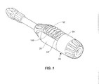
- FIG. 1 is a perspective view of a sprayer valve that uses the new invention.
- FIGS. 2-4 are front end, side, and rear elevation views of that sprayer valve.
- FIGS. 5 and 6 are a cross-sectional views through lines 5-5 in fig. 4 , with the sprayer valve in a closed position in fig. 5 and in an open position in fig. 6 .
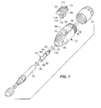
- FIG. 7 is an exploded perspective view.
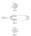
- FIG. 8 is a perspective view of another sprayer valve that uses the new invention.
- FIGS. 9-11 are front end, side, and rear elevation views of that sprayer valve.
- FIGS. 12 and 13 are cross-sectional views of the sprayer valve, with the sprayer valve in a closed position in fig. 12 and in an open position in fig. 13 .
- FIG. 14 is an exploded perspective view.
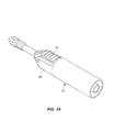
- FIG. 15 is a perspective view of third sprayer valve that uses the new invention.
- FIGS. 16-18 are front end, side, and rear elevation views of that sprayer valve.
- FIGS. 19 and 20 are cross-sectional views of the sprayer valve, with the sprayer valve in a closed position in fig. 19 and in an open position in fig. 20 .
- FIG. 21 is an exploded perspective view.
- Figs. 1-7 show a sprayer valve 20 that uses the same body and pin that was used in H.D. Hudson's prior sprayer valves.
- Figs. 8-21 show two other sprayer valves 22 and 23 that use a different body but a similar pin.
- All three sprayer valves have two general components, a body 30 and a slide/pin combination 32. In the discussion below, these components will first be discussed in general terms. Then the particular elements that differentiate the three sprayer valves will be discussed.
- the body in general
- the body 30 in each of the three illustrated sprayer valves has a front section 40, a rear section 42, and spaced wall sections 44.
- These bodies can be molded from rigid plastic or other suitable material, or, in some circumstances, cut from metal. Each of the elements of the body will be discussed in turn.
- the front section 40 is the front section 40
- the front section 40 of the body 30 on all three sprayer valves connects to a nozzle.
- the illustrated front sections are from 1 ⁇ 2 inch (12.7mm) to several inches long and have a diameter that tapers from less than an inch at the front, downstream end of the body to between 1 and 3 inches (25.4 and 76.2mm) at the upstream end of the front section.
- each illustrated sprayer valve has a cylindrical downstream bore 48 that communicates with a conventional liquid nozzle 50.
- the bore directs liquid that passes through the slide/pin combination 32 to the nozzle.
- Each of the illustrated downstream bores has a diameter of between 1/4 inch and 5/8 inches (6.4mm and 15.8mm).
- the downstream bore and the nozzle are connected by a tubular extension 52, which can be several inches to a foot (304.8mm) or more in length. In these sprayer valves, an upstream end of the extension fits within the downstream bore. Other arrangements can also be used.
- the rear section 42 of the body 30 on all three sprayer valves connects to a liquid supply.
- Each rear section has an external threaded portion 52, a liquid supply inlet 54, and an upstream bore 56.
- the illustrated threaded portions 52 are from 1/4 inch to 2 inches (6.35mm to 50mm) in length, and have a diameter that is slightly smaller than the diameter of the upstream end of the front section 40.
- These threads engage internal threads on a shut-off nut 58 that has an external diameter that general matches the diameter of the upstream end of the front section 40 of the body 30, and has a rear opening 60 that accommodates the outer periphery of a liquid supply line (not shown).
- the liquid supply inlet 54 of each of the illustrated rear sections 42 is located upstream of the threaded portion 52 and has a barb 62 that locks onto the liquid supply line that is inserted into the rear opening 60, holding the liquid supply line in place.
- the upstream bore 56 in the rear section 42 starts at the liquid supply inlet 54, where it receives liquid from the liquid supply line.
- This first part 64 of the upstream bore has a relatively small cross-sectional area.
- this part of the upstream bore be cylindrical. In the illustrated sprayer valves, the diameter of this part of the upstream bore is between 1/8 of an inch and 3/8 of an inch (3.2mm and 9.5mm).
- a second part 66 of the upstream bore 56 is located downstream of the first part 64.
- This part has a larger cross-sectional area than the first part and is generally short in length. Again, it may be preferred that this part of the upstream bore be cylindrical.
- the second part of the upstream bore is between 1/8 of an inch and 3/4 of an inch (3.2mm and 19.1mm) in length, and between 3/16 of an inch and 1/2 inch (4.8mm and 12.7mm) in diameter.
- a third part 68 of the upstream bore 56 is located downstream of the second part 66.
- This part has a larger cross-sectional area than the second part and is generally somewhat longer than the second part. Again, it may be preferred that this part of the upstream bore be cylindrical.
- the third part of the upstream bore is between 3/8 of an inch and 1 inch (9.5mm and 25.4mm) length, and between 1/4 of an inch and 5/8 inch (6.4mm and 16mm) in diameter.
- the front section 40 and the rear section 42 of the body 30 are joined by the spaced wall segments 44, which extend from the front section to the rear section.
- a recess 70 is provided between two wall of the segments, providing access to the upstream and downstream bores 48 and 56.
- the recess is between 3/8 of an inch and 1 inch (9.5mm and 25.4mm) in width, and between 1/2 inch and 11 ⁇ 4 inch (12.7mm and 31.8mm) in length.
- the slide/pin combination 32 in general
- the slide/pin combination 32 is mounted for axial movement with respect to the body 30 between an open position and a closed position.
- the slide/pin combination has a pin portion 74 and a slide portion 76, best seen in figs. 7 , 14 , and 21 . Each of these elements will also be discussed in turn.
- each of the illustrated sprayer valves has an upstream section 80 and a downstream section 82, separated by a narrowed waist 84.
- the pin portion may be made of metal or rigid plastic.
- the pin portion need be only between an inch (25.4mm) and a few inches in length, and between 1/8 of an inch and 1/2 inch (3.2mm and 12.7mm) in diameter. Potentially aiding in manufacture, the pin portion can often be circular in cross section throughout most of its length.
- the downstream section 82 of the pin portion 74 fits within the downstream bore 48 of the body 30.
- a first radial slot 88 in this section of the pin portion is fitted with a first o-ring 90 that forms an upstream seal in the downstream bore.
- liquid enters the downstream bore when the slide/pin combination 32 is in the open position. This seal prevents that liquid from leaking into the recess 70.
- the upstream bore 56 of the body 30 receives liquid from a liquid supply line.
- the slide/pin combination 32 is in the closed position (as seen in figs 5 , 12 , and 19 )
- the first upstream section 80 of the pin portion 74 of the illustrated sprayer valves fits snugly within the first part 64 of the upstream bore 56.
- the fit between the first upstream section of the pin portion and the upstream bore substantially prevents liquid in the upstream bore from flowing past the first upstream section, and thus substantially prevents liquid from flowing through the sprayer valve.
- the first upstream section 80 of the pin portion 74 has a cross-sectional area of less than .002 square inches.
- this relatively small cross-sectional area limits the force of liquid acting on that face of the pin portion, and thus helps to prevent the pressure of liquid from the liquid supply from pushing the slide/pin combination 32 to the open position.
- the liquid pressure that is exerted when the sprayer valve is in the closed position can be overcome by many means, including, for example, friction within the valve body 30 or even a conventional latch on the slide portion 76.
- the slide/pin combination 32 When the slide/pin combination 32 is moved to the open position, as seen in figs 6 , 13 , and 20 , the first upstream section 80 of the pin portion 74 retracts into the second part 66 of the upstream bore 56. In this position, the first part 64 of the upstream bore is opened, enabling liquid in the first part of the upstream bore to flow into the second part of the upstream bore.
- the second part 66 of the upstream bore 56 has a larger cross-sectional area than the first part 64 of the upstream bore, liquid in the second part can flow past the first upstream section 80 of the pin portion 74.
- the second upstream section 82 of the pin portion 74 may have a larger cross-sectional area than the first upstream section 80.
- the second upstream section 82 of each of the illustrated sprayer valves also has a second radial slot 90 in which is mounted a second o-ring 92.
- this o-ring provides a seal against the second part 66 of the upstream bore 56, acting as a further barrier to flow through the sprayer valve.
- the slide/pin combination is moved to the open position (as seen in figs. 6 , 13 , and 20 )
- this o-ring retracts into the third part 68 of the upstream bore. That movement permits liquid in the second part of the upstream bore to flow into the third part 69 of the upstream bore.
- the third upstream section 96 of the pin portion 74 of the slide/pin combination 32 fits within the third part 69 of the upstream bore 56.
- each of the illustrated third upstream sections has a cross-sectional area that is even larger than the cross-sectional area of the second upstream section 80. It is important for the third upstream section to block flow of liquid into the recess 70.
- Each of the illustrated third upstream sections has a third o-ring 100 that is mounted in a third radial slot 102. This o-ring provides a seal that forms a downstream boundary in the third part of the upstream bore, preventing liquid in that part from flowing into the recess.
- the waist 84 separates the downstream section 82 of the pin portion 74 and the third upstream section 96 of the pin portion.
- the waist extends between the upstream bore 56 and the downstream bore 48 in the body 30, and can be accessed through the recess 70.
- the waist has front and rear radial faces 106, 108 that extend outwardly to the upstream end of the downstream section of the pin portion, and to the downstream end of the third upstream section.
- the radial faces are inclined at an angle of between 45 and 90 degrees with respect to the axis of the sprayer valve. These faces serve as contact points with the slide portion 76, as will be discussed in more detail below.
- the waist has a diameter of between 1/8 of an inch and 3/8 of an inch (3.2mm and 9.5mm), with radial faces that are between 1/32 of an inch and 1/8 of an inch (0.8mm and 3.2mm) deep.
- a central passage 110 extends through the pin portion 74, providing a channel that conducts liquid from the upstream bore 56 of the body 30 to the downstream bore 48.
- the passage is between 1/16 of an inch and 1/4 of an inch (1.6mm and 6.4mm) in diameter, and begins at a series of radial inlets 112 that are located in the second upstream section 80 of the pin portion 74 of the slide/pin combination 32, between the second and third o-rings 92 and 100.
- these inlets are between 1/32 of an inch and 1/8 inch (0.8mm and 3.2mm) in diameter, and extend at right angles from the channel. In some cases, a single inlet would be sufficient.
- the central passage 110 in each of the illustrated sprayer valves extends between 3/4 of an inch (19.1mm) and several inches downstream from the inlets 112.
- the passage terminates at an outlet 114 that is located downstream of the first o-ring 90.
- the outlet is located on a downstream-facing end of the pin portion 74, although other locations are also possible.
- the slide portion 76 of the slide/pin combination 32 locks onto the pin portion 74 and provides a surface that a user can move linearly to move the slide/pin combination axially between the open and closed positions. It will generally be preferred that this element be made from molded plastic, but in many arrangements other materials can also be used.
- the slide portion has a base section 120 that fits within the recess 70 in the body 30, providing an exposed outer surface 122 that can be accessed by a user.
- the illustrated base sections are between 1/2 inch (12.7mm) and several inches in length, with a similar or slightly narrower width.
- the slide portion 76 on each of the illustrated sprayer valves also has resilient arms 126 that engage the front and rear radial faces 106, 108 on the waist 84 of the pin portion 74, providing a rigid axial connection between the slide portion and the pin portion.
- This rigid connection (in which some rotation of the pin portion about its axis is possible) results in linear movement of the slide portion being directly transferred to the pin portion, without the need for converting one form of movement to another kind of movement (i.e., rotational movement to linear movement), as was required in the prior version of the sprayer valve.
- the illustrated arms extend over opposed sides of the waist and have tangs 130 that lock onto a lower side of that waist.
- the illustrated arms have concavely curved inner surfaces that match the convexly curved outer profile of the waist on the pin portion.
- distally sloping ramp portions 132 on the tangs 130 first engage the waist 84 as the slide portion 76 is initially located within the recess 70. These ramp portions deflect outwardly as the slide portion is pressed downwardly into the recess, opening the spacing between the tangs. Once points 134 on the tangs pass the widest point of the waist, the arms spring back, trapping the waist between the tangs and holding the slide portion in place without the need for separate fasteners such as screws, etc.
- the slide portion 76 has one or more sets of spaced arms 126. Axial movement between the pin portion 74 and the slide portion is resisted by (1) engagement of a downstream facing face 140 on the arms with the front radial face 106 on the waist section and (2) and engagement of an upstream facing face 142 on the arms with the back radial face 108 on the waist. Other arrangements can also be used.
- the sprayer valve seen in figures 1-7 is an arrangement that uses the same type body 30 that was used on previous H.D. Hudson sprayer valves that used a lever-style on/off switch. That body has an opposed chamber 150 that is positioned radially across from the recess 70, on the opposite side of the pin portion 74 of the slide/pin combination 32. A radial groove in that chamber has an internal, upstream-facing shoulder 152 that is spaced from the pin portion. In prior, lever-type sprayer valves, that shoulder served as a fulcrum for the lever-style switch.
- the recess 70 within the spaced wall segments 44 in the body 30 used in this sprayer valve has a concavely curved outer surface 156.
- the slide portion 76 has a convexly curved base 158.
- An outwardly extending flattened section 160 extends out of the recess and fits over linear parts 162 of the wall segments, with curved sections of the base extending forwardly and rearwardly from the flattened section, laterally between the spaced wall segments.
- downstream facing face 140 and the upstream facing face 142 of the slide portion 76 of the slide/pin combination 32 are both part of the same wide arms 126. As will be seen below, other arrangements are also possible.
- This sprayer valve is particularly useful because it enables a manufacturer to produce a sprayer valve with an axially-moving switch using a body that was designed for use with a lever-style switch, without the need for separate fasteners. Putting the old body to a new use can facilitate manufacturing and save costs.
- the sprayer valves seen in figures 8-21 use a different body 30 than the one seen in figures 1-7 .
- the recess 70 does not have a curved outer surface. Instead, it has recessed linear wall segments 170 that extend axially on opposed sides of the pin portion 74.
- the slide portion 76 has a planar base 172 that slides along an outer surface of those linear wall segments. This arrangement reduces the risk of the slide portion being wedged away from the body, and inadvertently detaching from the pin portion 74.
- downstream facing face 140 and the upstream facing face 142 of the slide portion 76 of the slide/pin combination 32 are parts of separate arms 126 that are spaced apart. This arrangement saves material and thus may reduce costs.
Landscapes
- Engineering & Computer Science (AREA)
- General Engineering & Computer Science (AREA)
- Physics & Mathematics (AREA)
- Fluid Mechanics (AREA)
- Mechanical Engineering (AREA)
- Nozzles (AREA)
- Catching Or Destruction (AREA)
- Special Spraying Apparatus (AREA)
Applications Claiming Priority (1)
| Application Number | Priority Date | Filing Date | Title |
|---|---|---|---|
| US13/215,739 US8777131B2 (en) | 2011-08-23 | 2011-08-23 | Springless shut-off valve for liquid sprayers |
Publications (1)
| Publication Number | Publication Date |
|---|---|
| EP2561930A1 true EP2561930A1 (fr) | 2013-02-27 |
Family
ID=46000758
Family Applications (1)
| Application Number | Title | Priority Date | Filing Date |
|---|---|---|---|
| EP12162446A Withdrawn EP2561930A1 (fr) | 2011-08-23 | 2012-03-30 | Robinet de sectionnement sans ressort pour pulvérisateurs de liquide |
Country Status (2)
| Country | Link |
|---|---|
| US (1) | US8777131B2 (fr) |
| EP (1) | EP2561930A1 (fr) |
Cited By (1)
| Publication number | Priority date | Publication date | Assignee | Title |
|---|---|---|---|---|
| US20180050353A1 (en) * | 2016-08-18 | 2018-02-22 | Xiamen Solex High-Tech Industries Co., Ltd. | Water stop device and shower head |
Families Citing this family (3)
| Publication number | Priority date | Publication date | Assignee | Title |
|---|---|---|---|---|
| US10265708B2 (en) * | 2014-07-15 | 2019-04-23 | Lunatec, Inc. | Pressurizable fluid container and flexible dispenser |
| US20180258627A1 (en) * | 2017-02-24 | 2018-09-13 | Salvador Roxas | Handheld Bidet Attachment Device |
| WO2019079791A1 (fr) * | 2017-10-20 | 2019-04-25 | Green Garden Products Company, LLC | Appareil de pulvérisation avec ensemble tube d'écoulement |
Citations (3)
| Publication number | Priority date | Publication date | Assignee | Title |
|---|---|---|---|---|
| US4933569A (en) | 1988-07-18 | 1990-06-12 | H. D. Hudson Manufacturing Co. | Shut-off valve for sprayer |
| WO1993014880A1 (fr) * | 1992-01-31 | 1993-08-05 | Creative Real Estate Corp. | Appareil d'hydrotherapie |
| GB2461139A (en) * | 2009-04-01 | 2009-12-30 | Globe Union Ind Corp | A pull-out spray head for a kitchen sink faucet |
Family Cites Families (18)
| Publication number | Priority date | Publication date | Assignee | Title |
|---|---|---|---|---|
| USRE26013E (en) | 1966-05-03 | Hose nozzle | ||
| US801210A (en) | 1904-11-19 | 1905-10-10 | William K Mason | Hose-nozzle. |
| US1428530A (en) | 1920-06-08 | 1922-09-12 | Gabriel J Cassidy | Sprayer nozzle |
| US3006560A (en) | 1958-11-14 | 1961-10-31 | Lafayette Brass Mfg Co Inc | Spray gun |
| US3071402A (en) | 1959-09-28 | 1963-01-01 | Air Vac Engineering Company In | Vacuum-operated probe tools |
| US3072345A (en) | 1962-05-18 | 1963-01-08 | Robert J Lennon | Hose nozzle |
| US3419197A (en) * | 1967-10-06 | 1968-12-31 | Battaglia Anthony | Hair spray device |
| US3632083A (en) | 1970-02-11 | 1972-01-04 | Gen Electric | Valve for pressurized fluid system |
| US3768777A (en) | 1971-04-26 | 1973-10-30 | V Hechler | Liquid spray device |
| GB1571797A (en) * | 1975-12-09 | 1980-07-16 | Humbrol Ltd | Apparatus for spraying liquids |
| US4161289A (en) * | 1978-04-14 | 1979-07-17 | Cbs Inc. | Airbrush |
| AU540631B2 (en) * | 1982-01-05 | 1984-11-29 | Ube Industries, Ltd. | Flow adjusting valve for die casting machine |
| US4764047A (en) * | 1987-05-22 | 1988-08-16 | Suncast Corporation | Vehicle and patio washing brush |
| US5094400A (en) * | 1991-01-18 | 1992-03-10 | Ching Fu H | Spraying apparatus |
| US5143299A (en) * | 1991-03-26 | 1992-09-01 | Melnor Industries, Inc. | Spray gun |
| US6749133B1 (en) * | 2000-08-11 | 2004-06-15 | Green Garden Products Company | Spraying apparatus with insert |
| US7185243B1 (en) * | 2001-06-04 | 2007-02-27 | Lsi Logic Corporation | Testing implementation suitable for built-in self-repair (BISR) memories |
| CA2410997A1 (fr) * | 2002-10-31 | 2004-04-30 | Marmospray 2000 Inc. | Pistolet pulverisateur |
-
2011
- 2011-08-23 US US13/215,739 patent/US8777131B2/en not_active Expired - Fee Related
-
2012
- 2012-03-30 EP EP12162446A patent/EP2561930A1/fr not_active Withdrawn
Patent Citations (3)
| Publication number | Priority date | Publication date | Assignee | Title |
|---|---|---|---|---|
| US4933569A (en) | 1988-07-18 | 1990-06-12 | H. D. Hudson Manufacturing Co. | Shut-off valve for sprayer |
| WO1993014880A1 (fr) * | 1992-01-31 | 1993-08-05 | Creative Real Estate Corp. | Appareil d'hydrotherapie |
| GB2461139A (en) * | 2009-04-01 | 2009-12-30 | Globe Union Ind Corp | A pull-out spray head for a kitchen sink faucet |
Cited By (2)
| Publication number | Priority date | Publication date | Assignee | Title |
|---|---|---|---|---|
| US20180050353A1 (en) * | 2016-08-18 | 2018-02-22 | Xiamen Solex High-Tech Industries Co., Ltd. | Water stop device and shower head |
| US10220395B2 (en) * | 2016-08-18 | 2019-03-05 | Xiamen Solex High-Tech Industries Co., Ltd. | Water stop device and shower head |
Also Published As
| Publication number | Publication date |
|---|---|
| US20130048761A1 (en) | 2013-02-28 |
| US8777131B2 (en) | 2014-07-15 |
Similar Documents
| Publication | Publication Date | Title |
|---|---|---|
| US10502333B2 (en) | Ball valve with components integrated into the ball member | |
| US7661609B2 (en) | Pressure washer with soft start washer wand | |
| US7380731B1 (en) | Water sprayer having two water different spraying modes | |
| EP2561930A1 (fr) | Robinet de sectionnement sans ressort pour pulvérisateurs de liquide | |
| EP0527162B1 (fr) | Dispositif distributeur | |
| EP2352695B1 (fr) | Agencement de soupape de distribution pour un récipient | |
| US8074844B2 (en) | Piston pump stroke adjustment mechanism | |
| US11859374B2 (en) | Faucet spray head alignment system | |
| CA2444889A1 (fr) | Clapet a utiliser avec une seringue et empechant le refoulement | |
| US9114416B2 (en) | Nozzle opening/shutting device for airless type cosmetic vessel | |
| CN107061773B (zh) | 水龙头组件 | |
| US20130119156A1 (en) | Paint sprayer | |
| US8087640B2 (en) | Flow valve for example for faucets | |
| US7213616B2 (en) | Diversion valve fluid coupling | |
| US20070080242A1 (en) | Faucet side spray with metal plated exterior and interior structures, and with inert internal waterway | |
| US5823395A (en) | Child-resistant pump dispenser | |
| US7997881B2 (en) | Combined prime valve and electrical pressure control for paint spray pumps | |
| JP2000505181A (ja) | 切換弁 | |
| US4662602A (en) | Metering valve | |
| US6908071B2 (en) | Self-closing faucet with shearing action | |
| US7090150B2 (en) | Activating mechanism for an intercept valve for a spray gun used in water cleaner apparatus | |
| CA2512799A1 (fr) | Robinet de sectionnement a joue rotative | |
| US20100171053A1 (en) | Tap adaptors | |
| US3225972A (en) | Fluid dispenser | |
| EP1675685B1 (fr) | Pistolets d'arrosage |
Legal Events
| Date | Code | Title | Description |
|---|---|---|---|
| PUAI | Public reference made under article 153(3) epc to a published international application that has entered the european phase |
Free format text: ORIGINAL CODE: 0009012 |
|
| AK | Designated contracting states |
Kind code of ref document: A1 Designated state(s): AL AT BE BG CH CY CZ DE DK EE ES FI FR GB GR HR HU IE IS IT LI LT LU LV MC MK MT NL NO PL PT RO RS SE SI SK SM TR |
|
| AX | Request for extension of the european patent |
Extension state: BA ME |
|
| STAA | Information on the status of an ep patent application or granted ep patent |
Free format text: STATUS: THE APPLICATION IS DEEMED TO BE WITHDRAWN |
|
| 18D | Application deemed to be withdrawn |
Effective date: 20130828 |