EP2561805B1 - Apparatus and method for measuring bioelectric signals - Google Patents
Apparatus and method for measuring bioelectric signals Download PDFInfo
- Publication number
- EP2561805B1 EP2561805B1 EP12181656.5A EP12181656A EP2561805B1 EP 2561805 B1 EP2561805 B1 EP 2561805B1 EP 12181656 A EP12181656 A EP 12181656A EP 2561805 B1 EP2561805 B1 EP 2561805B1
- Authority
- EP
- European Patent Office
- Prior art keywords
- interface
- signal
- electrodes
- bioelectric signal
- motion artifact
- Prior art date
- Legal status (The legal status is an assumption and is not a legal conclusion. Google has not performed a legal analysis and makes no representation as to the accuracy of the status listed.)
- Active
Links
- 238000000034 method Methods 0.000 title claims description 21
- 238000005259 measurement Methods 0.000 claims description 96
- 210000003491 skin Anatomy 0.000 claims description 94
- 238000000605 extraction Methods 0.000 claims description 39
- 210000000434 stratum corneum Anatomy 0.000 claims description 11
- 239000000463 material Substances 0.000 claims description 7
- 239000011810 insulating material Substances 0.000 claims description 6
- 239000000284 extract Substances 0.000 claims description 5
- 239000000758 substrate Substances 0.000 claims description 3
- 239000000017 hydrogel Substances 0.000 description 34
- 239000000853 adhesive Substances 0.000 description 25
- 230000001070 adhesive effect Effects 0.000 description 25
- 238000012545 processing Methods 0.000 description 24
- 230000003044 adaptive effect Effects 0.000 description 16
- 238000009413 insulation Methods 0.000 description 14
- 230000008859 change Effects 0.000 description 12
- 229910052751 metal Inorganic materials 0.000 description 6
- 239000002184 metal Substances 0.000 description 6
- 230000008569 process Effects 0.000 description 6
- 210000002615 epidermis Anatomy 0.000 description 5
- 238000013500 data storage Methods 0.000 description 4
- 239000010931 gold Substances 0.000 description 4
- BQCADISMDOOEFD-UHFFFAOYSA-N Silver Chemical compound [Ag] BQCADISMDOOEFD-UHFFFAOYSA-N 0.000 description 3
- 230000000875 corresponding effect Effects 0.000 description 3
- 238000003745 diagnosis Methods 0.000 description 3
- 201000010099 disease Diseases 0.000 description 3
- 208000037265 diseases, disorders, signs and symptoms Diseases 0.000 description 3
- 230000000694 effects Effects 0.000 description 3
- 230000036541 health Effects 0.000 description 3
- 210000000663 muscle cell Anatomy 0.000 description 3
- 210000002569 neuron Anatomy 0.000 description 3
- BASFCYQUMIYNBI-UHFFFAOYSA-N platinum Chemical compound [Pt] BASFCYQUMIYNBI-UHFFFAOYSA-N 0.000 description 3
- 208000020446 Cardiac disease Diseases 0.000 description 2
- 239000004020 conductor Substances 0.000 description 2
- 238000001514 detection method Methods 0.000 description 2
- 239000003792 electrolyte Substances 0.000 description 2
- 239000000499 gel Substances 0.000 description 2
- PCHJSUWPFVWCPO-UHFFFAOYSA-N gold Chemical compound [Au] PCHJSUWPFVWCPO-UHFFFAOYSA-N 0.000 description 2
- 229910052737 gold Inorganic materials 0.000 description 2
- 208000019622 heart disease Diseases 0.000 description 2
- 238000012986 modification Methods 0.000 description 2
- 230000004048 modification Effects 0.000 description 2
- 229910052709 silver Inorganic materials 0.000 description 2
- 239000004332 silver Substances 0.000 description 2
- HKZLPVFGJNLROG-UHFFFAOYSA-M silver monochloride Chemical compound [Cl-].[Ag+] HKZLPVFGJNLROG-UHFFFAOYSA-M 0.000 description 2
- 230000003321 amplification Effects 0.000 description 1
- 206010003119 arrhythmia Diseases 0.000 description 1
- 230000006793 arrhythmia Effects 0.000 description 1
- 239000003990 capacitor Substances 0.000 description 1
- 238000004590 computer program Methods 0.000 description 1
- 239000000470 constituent Substances 0.000 description 1
- 238000010276 construction Methods 0.000 description 1
- 230000001276 controlling effect Effects 0.000 description 1
- 230000002596 correlated effect Effects 0.000 description 1
- 230000008878 coupling Effects 0.000 description 1
- 238000010168 coupling process Methods 0.000 description 1
- 238000005859 coupling reaction Methods 0.000 description 1
- 230000003247 decreasing effect Effects 0.000 description 1
- 238000001914 filtration Methods 0.000 description 1
- 230000006870 function Effects 0.000 description 1
- 238000012544 monitoring process Methods 0.000 description 1
- 208000010125 myocardial infarction Diseases 0.000 description 1
- 238000003199 nucleic acid amplification method Methods 0.000 description 1
- 230000003287 optical effect Effects 0.000 description 1
- 229910052697 platinum Inorganic materials 0.000 description 1
- 230000000644 propagated effect Effects 0.000 description 1
- 238000012552 review Methods 0.000 description 1
- 239000004065 semiconductor Substances 0.000 description 1
Images


Classifications
-
- A—HUMAN NECESSITIES
- A61—MEDICAL OR VETERINARY SCIENCE; HYGIENE
- A61B—DIAGNOSIS; SURGERY; IDENTIFICATION
- A61B5/00—Measuring for diagnostic purposes; Identification of persons
- A61B5/72—Signal processing specially adapted for physiological signals or for diagnostic purposes
- A61B5/7203—Signal processing specially adapted for physiological signals or for diagnostic purposes for noise prevention, reduction or removal
- A61B5/7207—Signal processing specially adapted for physiological signals or for diagnostic purposes for noise prevention, reduction or removal of noise induced by motion artifacts
- A61B5/7214—Signal processing specially adapted for physiological signals or for diagnostic purposes for noise prevention, reduction or removal of noise induced by motion artifacts using signal cancellation, e.g. based on input of two identical physiological sensors spaced apart, or based on two signals derived from the same sensor, for different optical wavelengths
-
- A—HUMAN NECESSITIES
- A61—MEDICAL OR VETERINARY SCIENCE; HYGIENE
- A61B—DIAGNOSIS; SURGERY; IDENTIFICATION
- A61B5/00—Measuring for diagnostic purposes; Identification of persons
- A61B5/05—Detecting, measuring or recording for diagnosis by means of electric currents or magnetic fields; Measuring using microwaves or radio waves
-
- A—HUMAN NECESSITIES
- A61—MEDICAL OR VETERINARY SCIENCE; HYGIENE
- A61B—DIAGNOSIS; SURGERY; IDENTIFICATION
- A61B5/00—Measuring for diagnostic purposes; Identification of persons
- A61B5/24—Detecting, measuring or recording bioelectric or biomagnetic signals of the body or parts thereof
-
- A—HUMAN NECESSITIES
- A61—MEDICAL OR VETERINARY SCIENCE; HYGIENE
- A61B—DIAGNOSIS; SURGERY; IDENTIFICATION
- A61B5/00—Measuring for diagnostic purposes; Identification of persons
- A61B5/24—Detecting, measuring or recording bioelectric or biomagnetic signals of the body or parts thereof
- A61B5/316—Modalities, i.e. specific diagnostic methods
- A61B5/389—Electromyography [EMG]
-
- A—HUMAN NECESSITIES
- A61—MEDICAL OR VETERINARY SCIENCE; HYGIENE
- A61B—DIAGNOSIS; SURGERY; IDENTIFICATION
- A61B5/00—Measuring for diagnostic purposes; Identification of persons
- A61B5/72—Signal processing specially adapted for physiological signals or for diagnostic purposes
- A61B5/7228—Signal modulation applied to the input signal sent to patient or subject; demodulation to recover the physiological signal
-
- A—HUMAN NECESSITIES
- A61—MEDICAL OR VETERINARY SCIENCE; HYGIENE
- A61B—DIAGNOSIS; SURGERY; IDENTIFICATION
- A61B5/00—Measuring for diagnostic purposes; Identification of persons
- A61B5/05—Detecting, measuring or recording for diagnosis by means of electric currents or magnetic fields; Measuring using microwaves or radio waves
- A61B5/053—Measuring electrical impedance or conductance of a portion of the body
-
- A—HUMAN NECESSITIES
- A61—MEDICAL OR VETERINARY SCIENCE; HYGIENE
- A61B—DIAGNOSIS; SURGERY; IDENTIFICATION
- A61B5/00—Measuring for diagnostic purposes; Identification of persons
- A61B5/72—Signal processing specially adapted for physiological signals or for diagnostic purposes
- A61B5/7203—Signal processing specially adapted for physiological signals or for diagnostic purposes for noise prevention, reduction or removal
- A61B5/7207—Signal processing specially adapted for physiological signals or for diagnostic purposes for noise prevention, reduction or removal of noise induced by motion artifacts
- A61B5/721—Signal processing specially adapted for physiological signals or for diagnostic purposes for noise prevention, reduction or removal of noise induced by motion artifacts using a separate sensor to detect motion or using motion information derived from signals other than the physiological signal to be measured
Definitions
- This disclosure relates to methods and apparatuses for measuring bioelectric signals of a testee more accurately by removing a motion artifact from the bioelectric signals.
- Bioelectric signals are signals in the form of an electric potential or an electric current that are generated by muscle cells or nerve cells of a testee, and are obtained by analyzing changes in an electric signal detected by electrodes attached to the body of the testee.
- a motion artifact is generated in the biolectric signals due to movement of the testee. The motion artifact interferes with accurate measurement of bioelectric signals by distorting a waveform of a measurement result.
- FIG. 1 schematically illustrates an example of a structure of a bioelectric signal measurement apparatus 100.
- the bioelectric signal measurement apparatus 100 includes interfaces E1w (120), E1d (130), E2w (140), and E2d (150), a motion artifact extraction unit 160, and a bioelectric signal extraction unit 170.
- the motion artifact extraction unit 160 and the bioelectric signal extraction unit 170 constitute a signal processor 180.
- the bioelectric signal measurement apparatus 100 of FIG. 1 is a merely one example, and various modifications based on the constituent elements illustrated in FIG. 1 will be apparent to one of ordinary skill in the art to which the present description pertains.
- the bioelectric signal measurement apparatus 100 is used to measure bioelectric signals of a testee 110.
- Bioelectric signals are signals in the form of an electric potential or an electric current that are generated by muscle cells or nerve cells of a human body, and may be referred to as bioelectric potentials or bioelectric currents.
- bioelectric potentials or bioelectric currents For convenience of explanation, it will be assumed that the bioelectric signals detected using the bioelectric signal measurement apparatus 100 are in the form of an electric potential.
- the bioelectric signal measurement apparatus 100 detects bioelectric signals using the interfaces E1w (120), E1d (130), E2w (140), and E2d (150) attached to the body of the testee 110.
- the interfaces E1w (120), E1d (130), E2w (140), and E2d (150) are electrically connected to i.e., electrically interface with, the skin of the testee 110 to detect bioelectric signals of the testee 110. That is, the interfaces E1w (120), E1d (130), E2w (140), and E2d (150) are electrodes that electrically contact a living body and output electric signals from the living body to a circuit for measuring bioelectric signals.
- Each of the interfaces E1w (120), E1d (130), E2w (140), and E2d (150) includes one or more electrodes. If an interface has more than one electrode, the electrodes are connected together at a node so that all of the electrodes of the interface have the same electric potential.
- the one or more electrodes of the interface are arranged in various ways for accurate detection of a bioelectric signal, and contact the skin of the testee 110 either directly, or indirectly via a predetermined material, as will be described below.
- the arrangement of the electrodes of the interfaces E1w (120), E1d (130), E2w (140), and E2d (150) will be described below with reference to FIGS. 4 , 5 , 7A, and 7B .
- a bioelectric signal is measured by detecting a difference between electric potential values, that is, voltages, detected by two interfaces E1w (120) and E2w (140) having different electric potentials at positions separated from each other by a predetermined distance.
- a bioelectric signal is measured by differentially amplifying electric potential values acquired from the two interfaces E1w (120) and E2w (140) attached at positions separated from each other by the predetermined distance on the skin of the testee 110 to obtain a waveform of a voltage value corresponding to the bioelectric signal.
- the waveform of the voltage value of the measured bioelectric signal includes noise.
- the bioelectric signal corresponding to an electric potential or an electric current generated in nerve cells or muscle cells is an electric signal having a very small amplitude, and thus is greatly affected by noise.
- the bioelectric signal measurement apparatus 100 measures bioelectric signal using the electrodes of the interfaces E1w (120) and E2w (140) attached to a human body, so the bioelectric signal including noise that is measured is influenced by movement of the body during the measurement of the bioelectric signal through the attached electrodes.
- the noise due to the movement of the body is referred to as a motion artifact, and deteriorates accuracy of the measured bioelectric signal so that accurate recognition of an actual state of the testee 110 and diagnosis and treatment of a disease are made difficult.
- the motion artifact is due to a variation in an electrode-skin contact impedance (hereinafter referred to as a contact impedance) between the skin and the electrode due to the movement of the body.
- a contact impedance an electrode-skin contact impedance
- Such a contact impedance variation generates noise the measured bioelectric signal.
- the motion artifact distorts the waveform of the measured bioelectric signal, and therefore the motion artifact due to the movement of the body must be removed from the measured bioelectric signal for accurate measurement of the bioelectric signal.
- the motion artifact does not have a constant pattern, and often varies according to the movement of the body.
- the motion artifact is a signal in a frequency range similar to a frequency range of a bioelectric signal to be measured, and therefore the motion artifact cannot be removed from the measured bioelectric signal by simple filtering.
- the bioelectric signal measurement apparatus 100 measures a signal proportional to the motion artifact separate from a bioelectric signal including the motion artifact, and removes the signal from the bioelectric signal including the motion artifact using the signal proportional to the motion artifact, thereby obtaining a bioelectric signal free of the motion artifact.
- the motion artifact is generated because the contact impedance variation of the testee 110 due to movement causes a change in the electric potential generated by the electrode, which appears as noise in the measured bioelectric signal.
- the motion artifact is measured by using the contact impedance variation, which is highly correlated with the motion artifact. That is, the motion artifact affecting a bioelectric signal may be measured by measuring a signal proportional to the contact impedance variation due to movement.
- the signal proportional to the contact impedance variation due to movement may be measured by flowing a current i0 from the electrode into the body of the testee 110, detecting a change ⁇ v in an electric potential produced by the current i0 using the electrodes attached to the body and separated from each other by a predetermined distance, and differentially amplifying the change ⁇ v in the electric potentials detected by the electrodes.
- the change ⁇ v in the electric potential produced by the constant current i0 is proportional to the contact impedance variation.
- the motion artifact is measured by making the current i0 flow into the skin and using the change ⁇ v of the electric potential detected by the electrodes attached to the skin.
- the current i0 flowing into the skin of the testee 110 has a frequency fc that does not overlap with the frequency range of a bioelectric signal so that the effect of a bioelectric signal with respect to the measured motion artifact may be reduced.
- the change ⁇ v of the detected electric potential is a signal modulated at the frequency fc.
- the signal modulated at the frequency fc is detected and demodulated to recover the original signal.
- the change ⁇ v of the detected electric potential may be detected by using the interfaces E1d (130) and E2d (150) formed of one or more electrodes attached to the skin of the testee 110 separate from the measurement of a bioelectric signal. That is, the bioelectric signal measurement apparatus 100 measures the bioelectric signal using the two interfaces E1w (120) and E2w (140), and detects the electric potential signal ⁇ v using the two separate interfaces E1d (130) and E2d (150).
- the electrodes of the interfaces E1w (120) and E2w (140) for detecting the bioelectric signal electrically interface with the skin of the testee 110 using a hydrogel 270 (see FIG. 2 ).
- the hydrogel 270 is an electrolyte gel.
- a contact impedance which is an electrical resistance between the electrode and the skin, is reduced, compared to a case in which an electrode formed of a conductive metal directly contacts the skin. That is, since the contact impedance between the electrode and the skin is decreased by using the hydrogel 270, the influence of the contact impedance on a bioelectric signal having a small amplitude is reduced, which is advantageous for the measurement of the bioelectric signal.
- the bioelectric signal measurement apparatus 100 to have an appropriate signal to noise ratio (SNR) for detecting a bioelectric signal.
- SNR signal to noise ratio
- the electrodes of the interfaces E1d (130) and E2d (150) that detect the electric potential signal ⁇ v detect a signal by directly contacting the skin without the hydrogel 270.
- the electrodes of the interfaces E1d (130) and E2d (150) that directly contact the skin without the hydrogel 270 have a higher contact impedance than the interfaces E1w (120) and E2w (140) that electrically interface with the skin using the hydrogel 270.
- the interfaces E1w (120) and E2w (140) that detect the bioelectric signal electrically interface with the skin in a different state than the interfaces E1d (130) and E2d (150) that detect the electric potential signal ⁇ v, and have different electrical conditions than the interfaces E1d (130) and E2d (150), which means that the interfaces E1d (130) and E2d (150) that detect the electric potential signal ⁇ v have a higher contact impedance than the interfaces E1w (120) and E2w (140) that detect the bioelectric signal.
- FIG. 2 is a cross-sectional view of an example of a contact surface where the bioelectric signal measurement apparatus 100 of FIG. 1 contacts the skin of the testee 110.
- electrodes 231 and 232 of the interface E1d (130) and electrodes 251 and 252 of the interface E2d (150) that detect the electric potential signal ⁇ v directly contact the skin of the testee 110 via holes of an adhesive sheet 210.
- electrodes 221 and 222 of the interface E1w (120) and electrodes 241 and 242 of the interface E2w (140) that detect the bioelectric signal contact the skin of the testee 110 via the hydrogel 270, i.e., they do not directly contact the skin of the testee 110, but indirectly contact the skin of the testee 110 via the hydrogel 270.
- the hydrogel 270 which is an electrolyte gel as described above, electrically interfaces with the skin of the testee 110 and the electrodes 221 and 222 of the interface E1w (120) and the electrodes 241 and 242 of the interface E2w (140) that detect the bioelectric signal.
- An electrode made of a conductive metal that electrically interfaces with the skin via the hydrogel 270 is referred to as a wet electrode.
- An electrode made of a conductive metal that electrically interfaces with the skin via direct contact is referred to as a dry electrode.
- a wet electrode is a silver plate coated with silver chloride (AgCl)
- a dry electrode is a plate made of gold (Au).
- Au gold
- the interfaces E1 d (130) and E2d (150) that detect the electric potential signal ⁇ v use dry electrodes having a high contact impedance. Compared to a wet electrode, a dry electrode has a higher correlation between a change in the contact impedance and a motion artifact. Thus, more accurate measurement of bioelectric signals free of a motion artifact is possible by using dry electrodes in the detection of the electric potential signal ⁇ v.
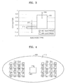
- FIG. 3 is a graph showing an example of a correlation between a motion artifact and a change in contact impedance according to the type of electrodes of interfaces of the bioelectric signal measurement apparatus 100 of FIG. 1 .
- the correlation signifies a degree of correlation between two variables, in this case, between the contact impedance variation and the motion artifact.
- a large correlation signifies that the degree of correlation between the contact impedance variation and the motion artifact is large. Accordingly, for the electrode having a large correlation, the variation in the contact impedance due to the contact between the electrode and the skin of the testee 110 more accurately reflects the motion artifact included in the bioelectric signal during the measurement of the bioelectric signal.
- the x axis denotes the type of an electrode, that is, a wet electrode and a dry electrode
- the y axis denotes a correlation between the contact impedance variation and the motion artifact by a correlation coefficient.
- the correlation coefficient is a value quantitatively indicating a degree of correlation between the contact impedance variation and the motion artifact, and may have a value between -1 to +1. The larger the absolute value of the correlation coefficient is, the higher the correlation is. When the correlation coefficient value is 0, no correlation exists.
- An area 310 denotes an average correlation coefficient value of a dry electrode.
- An area 330 denotes an average correlation coefficient value of a wet electrode.
- a line 320 denotes a range of a standard deviation of the average correlation coefficient value of a dry electrode.
- a line 340 denotes a range of a standard deviation of the average correlation coefficient value of a wet electrode.
- the average correlation coefficient value (area 330) of a wet electrode is about 0.13, indicating a low correlation between the contact impedance and the motion artifact, while the average correlation coefficient value (area 310) of a dry electrode exhibits a high correlation coefficient value of about 0.75, indicating a high correlation between the contact impedance variation and the motion artifact.
- the average correlation coefficient value (area 310) of a dry electrode of 0.75 is about 5.8 times the average correlation coefficient value (area 330) of a wet electrode of 0.13.
- the absolute value of the correlation coefficient of a dry electrode is greater than the absolute value of the correlation coefficient of a wet electrode.
- the contact impedance variation accurately reflects the motion artifact so that a more accurate measurement of the motion artifact is possible.
- the reason the correlation of the dry electrode is relatively high is because the contact impedance of the dry electrode that directly contacts the skin is relatively high compared to the contact impedance of the wet electrode that contacts the skin via the hydrogel 270. This is because the contact impedance variation due to movement appears greater when the measurement is performed using the dry electrode than using the wet electrode.
- the bioelectric signal measurement apparatus 100 performs measurement using wet electrodes having a relatively low contact impedance that has a relatively low correlation with a motion artifact as the electrodes of the interfaces E1w (120) and E2w (140) for the detecting bioelectric signal, and using dry electrodes having a relatively high contact impedance that has a relatively high correlation with a motion artifact as the electrodes of the interfaces E1d (130) and E2d (150) for measuring the electric potential signal ⁇ v.
- the motion artifact measured using he electrodes of the interfaces E1 d (130) and E2d (150) has almost the same shape as the motion artifact included in the bioelectric signal.
- the electrodes of the interfaces E1 d (130) and E2d (150) for measuring the electric potential signal ⁇ v are disposed within a critical distance from the electrodes of the interfaces E1w (120) and E2w (140) for measuring the bioelectric signal.
- the contact impedance variation at the electrodes for measuring the electric potential signal ⁇ v must have almost the same shape as the contact impedance variation at the electrodes for measuring the bioelectric signal. Therefore, the critical distance is a distance that is short enough so that a contact impedance variation due to movement of the testee 110 appears at the electrodes for detecting the electric potential signal ⁇ v has almost the same shape as a contact impedance variation at the electrodes for detecting the bioelectric signal.
- (150) for measuring the electric potential signal ⁇ v is separated from at least one of the electrodes 221 and 222 of the interface E1w (120) and the electrodes 241 and 242 of the interface E2w (140) for measuring the bioelectric signal by the critical distance or less.
- the detailed structure of the electrodes 231 and 232 of the interface E1d (130) and the electrodes 251 and 252 of the interface E2d (150) for measuring the electric potential signal ⁇ v and the electrodes 221 and 222 of the interface E1w (120) and the electrodes 241 and 242 of the interface E2w (140) for measuring the bioelectric signal are described as follows with reference to FIG. 2 .
- the adhesive sheet 210 for measuring the bioelectric signal
- an electrode 260 of a reference interface E3w for measuring a reference electric potential for the bioelectric signal
- the hydrogel 270 for measuring a reference electric potential for the bioelectric signal
- an insulation layer 280 for measuring a reference electric potential for the bioelectric signal
- the adhesive sheet 210 is a sheet formed of an insulating material that has both sides are coated with an adhesive material, and keeps the bioelectric signal measurement apparatus 100 in contact with the skin. That is, the bioelectric signal measurement apparatus 100 contacts the skin via the adhesive sheet 210, and the state of contact is maintained by the adhesive material of the adhesive sheet 210. To enable an electric connection between the bioelectric signal measurement apparatus 100 and the skin of the testee 110, holes are punched at positions of the adhesive sheet 210 where the bioelectric signal measurement apparatus 100 contacts the skin. That is, the bioelectric signal measurement apparatus 100 electrically interfaces with the skin of the testee 110 through the interfaces E1w (120), E1d (130), E2w
- portions where the bioelectric signal measurement apparatus 100 electrically contacts the skin that is, positions where the holes are formed in the adhesive sheet 210, are places where the electrodes 221, 222, 231, 232, 241, 242, 251, and 252 forming the interfaces E1w (120), E1d (130), E2w (140), and E2d (150) are located.
- the electrodes 221, 222, 241, and 242 are electrodes forming the interfaces E1w (120) and E2w (140) for measuring the bioelectric signal, and therefore electrodes having a relatively low contact impedance are used as the electrodes 221, 222, 241, and 242 to reduce an influence of the motion artifact as described above.
- the electrodes 231, 232, 251, and 252 are electrodes forming the interfaces E1d (130) and E2d (150) for measuring the electric potential signal ⁇ v, and therefore electrodes having a relatively high correlation between the contact impedance variation and the motion artifact are used for the electrodes 231, 232, 251, and 252 as described above.
- the electrodes 221, 222, 241, and 242 that measure the bioelectric signal are wet electrodes that electrically interface with the skin of the testee 110 via the hydrogel 270, whereas the electrodes 231, 232, 251, and 252 that measure the electric potential signal ⁇ v are dry electrodes that directly contact the skin of the testee 110.
- the bioelectric signal measurement apparatus 100 measures the bioelectric signal based on a difference between the electric potential values measured at the two interfaces E1w (120) and E2w (140) located at positions separated from each other by a predetermined distance. Accordingly, the electrodes 221 and 222 forming the interface E1w (120) and the electrodes 241 and 242 forming the interface E2w (140) are located at positions separated from each other by a predetermined distance to measure voltages of the bioelectric signal.
- the electrodes 231-232 231 and 232 of the interface E1d (130) for measuring the electric potential signal ⁇ v are alternately arranged with the electrodes 221 and 222 of the interface E1w (120) for measuring the bioelectric signal at a spacing within the critical distance from the electrodes 221 and 222 of the interface E1w (120) so that the motion artifact measured using the electrodes 231 and 232 of the interface E1d (130) has almost the same shape as the motion artifact included in the bioelectric signal measured by the electrodes 221 and 222 of the interface E1w (120).
- the electrodes 251 and 252 of the interface E2d (150) for measuring the electric potential signal ⁇ v are alternately arranged with the electrodes 241 and 242 of the interface E2w (140) for measuring the bioelectric signal at a spacing within the critical distance from the electrodes 241 and 242 of the interface E2w (140) so that the motion artifact measured using the electrodes 251 and 252 of the interface E2d (150) has almost the same shape as the motion artifact included in the bioelectric signal measured by the electrodes 241 and 242 of the interface E2w (140).
- the reference interface E3w for measuring the reference electric potential for the bioelectric signal is formed of at least one electrode 260.
- the at least one electrode 260 of the reference interface E3w has the same structure as the electrodes 221, 222, 241, and 242 of the interfaces E1w (120) and E2w (140) for measuring the bioelectric signal.
- the reference interface E3w for measuring the reference electric potential for the bioelectric signal is located at a position separated a predetermined distance from the interfaces E1w (120) and E2w (140) for measuring the bioelectric signal so that the reference interface E3w is not influenced by the interfaces E1w (120) and E2w (140).
- the position of the reference interface E3w is merely an example, and the reference interface E3w may be located at other positions.
- the insulation layer 280 has a shape of a substrate and is formed of an insulating material that electrically isolates adjacent electrodes from each other to prevent current from flowing between the adjacent electrodes.
- the remaining area except for the areas where the electrodes and the hydrogel 270 are located is all formed by the insulation layer 280.
- the areas where the wet electrodes and the hydrogel 270 that closely contacts the wet electrodes are located may be configured to be concave to prevent an electrical connection between the hydrogel 270 and the dry electrodes. Since the dry electrodes and the wet electrodes are alternately arranged on the insulation layer 280, a cross-section of the insulation layer 280 has an uneven shape as illustrated in FIG.
- the structure of the insulation layer 280 having an uneven shape as illustrated in FIG. 2 is merely an example, and the insulation layer 280 may have any one of numerous different structures.
- the cross-section of the insulation layer 280 may have a flat shape like the insulation layer 1110 of the bioelectric signal measurement apparatus 100 illustrated in FIG. 11A .
- the contact surface 200 where the bioelectric signal measurement apparatus 100 contacts the skin of the testee 110 includes the adhesive sheet 210, the electrodes of the interfaces E1w (120) and E2w (140) for measuring the bioelectric signal, the electrodes of the interfaces E1d (130) and E2d (150) for measuring the electric potential signal ⁇ v, the electrode of the reference interface E3w (260), and the hydrogel 270.
- the shape of the contact surface 200, the types of the electrodes, and the arrangements of the electrodes of the bioelectric signal measurement apparatus 100 are not limited to those illustrated in FIG. 2 , but may be modified in numerous ways as will be apparent to one of ordinary skill in the art.
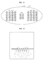
- FIGS. 4 , 5 , and 7A illustrate examples of bottom surfaces 400, 500, and 700 of the bioelectric signal measurement apparatus 100 on which the electrodes forming the interfaces of the bioelectric signal measurement apparatus 100 are arranged.
- the bottom surface 400 includes an adhesive sheet 410, electrodes 421-428 of an interface E1w for measuring a bioelectric signal, electrodes 441--448 of an interface E2w for measuring the bioelectric signal, electrodes 431-438 of an interface E1 d for measuring an electric potential signal ⁇ v, electrodes 451-458 of an interface E2d for measuring the electric potential signal ⁇ v, and an electrode 460 of a reference interface E3w for measuring a reference electric potential for the bioelectric signal.
- the two interfaces E1w and E2w for measuring the bioelectric signal measure electric potential values of the bioelectric signal at positions separated from each other by a predetermined distance.
- the electrodes 431-438 of the interface E1d for measuring the electric potential signal ⁇ v are alternately arranged with the electrodes 421-428 of the interface E1w for measuring the bioelectric signal at a spacing within the critical distance from the electrodes 421-428 of the interface E1w.
- the electrodes 421-428 of the interface E1w are at the same electric potential and form a single interface
- the electrodes 431-438 of the interface E1 d are at the same electric potential and form a same interface.
- the motion artifact measured using the electrodes 431-438 of the interface E1 d has almost the same shape as the motion artifact included in the bioelectric signal measured by the electrodes 421-428 of the interface E1w.
- the electrodes 451-458 of the interface E2d for measuring the electric potential signal ⁇ v are alternately arranged with the electrodes 441-448 of the interface E2w for measuring the bioelectric signal at a spacing within the critical distance from the electrodes 441-448 of the interface E2w, so the motion artifact measured using the electrodes 451-458 of the interface E2d has almost the same shape as the motion artifact included in the bioelectric signal measured by the electrodes 441-448 of the interface E2w.
- the electrode 460 of the reference interface E3w for measuring a reference electric potential for the bioelectric signal is separated by a predetermined distance from the interfaces E1w and E2w for measuring the bioelectric signal so that the interface E3w is not affected by the interfaces E1w and E2w.
- the electrodes 421-428 and 441-448 of the interfaces E1w and E2w for measuring the bioelectric signal and the electrode 460 of the reference interface E3w for measuring the reference electric potential for the bioelectric signal are wet electrodes that contact the skin via the hydrogel 270, whereas the electrodes 431-438 and 451-458 of the interfaces E1d and E2d for measuring the electric potential signal ⁇ v are dry electrodes that directly contact the skin.
- each electrode is located, and the remaining area the adhesive sheet 410 is formed of an insulating material. As illustrated in FIG. 2 , the wet electrodes and the dry electrodes are electrically isolated from each other by the insulating material of the insulation layer.
- the bottom surface 500 includes an adhesive sheet 510, electrodes 521-528 of an interface E1w for measuring a bioelectric signal, electrodes 541-548 of an interface E2w for measuring the bioelectric signal, electrodes 531-538 of an interface E1 d for measuring an electric potential signal ⁇ v, electrodes 551-558 of an interface E2d for measuring the electric potential signal ⁇ v, and electrodes 561-564 of a reference interface E3w.
- the interfaces E1w and E2w for measuring the bioelectric signal, the interfaces E1 d and E2d for measuring the electric potential signal ⁇ v, and the reference interface E3W for measuring the reference electric potential for the bioelectric signal are arranged like the interfaces E1w, E2w, E1d, E2d, and E3w of FIG. 4 .
- the reference interface E3w for measuring the reference electric potential for the bioelectric signal of FIG. 5 is formed of a plurality of electrodes 561-564 having the same electric potential, rather than being formed of single electrode 560 like the reference interface E3w of FIG. 4 .
- the electrodes 521-528 and 541-548 of the interfaces E1w and E2w for measuring the bioelectric signal of FIG. 5 and the electrodes 561-564 of the reference interface E3w for measuring the reference electric potential for the bioelectric signal are not wet electrodes electrically interfacing with the skin via the hydrogel 270, but are electrodes formed of a conductive material like the electrodes 531-538 and 551-558 of the interfaces E1d and E2d for measuring the electric potential signal ⁇ v.
- the electrodes 521-528, 541-548, and 560 of the interfaces E1w, E2w, and E3w each have a sharp protrusion to reduce the influence of the motion artifact on the bioelectric signal without the need to use the hydrogel 270 that maintains a low contact impedance with the skin.
- the sharp protrusions are indicated by black dots in the center of the electrodes 521-528, 541-548, and 560 of the interfaces E1w, E2w, and E3w in FIG. 5 .
- FIG. 6 is a cross-sectional view illustrating an example of the shape of the sharp protrusions of the electrodes forming the interfaces E1w, E2w, and E3w of FIG. 5 , and an example of a state in which electrodes having sharp protrusions penetrate the stratum corneum of the skin and make electrical contact with the epidermis beneath the stratum corneum.
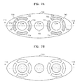
- the bottom surface 700 of FIG. 7A includes an electrode 720 of an interface E1w for measuring a bioelectric signal, an electrode 740 of an interface E2w for measuring the bioelectric signal, electrodes 731-734 of an interface E1d for measuring an electric potential signal ⁇ v, electrodes 751-754 of an interface E2d for measuring the electric potential signal ⁇ v, and an electrode 760 of a reference interface E3w for measuring a reference electric potential for the bioelectric signal.
- each of the interfaces E1w and E2w for measuring the bioelectric signal of FIG. 7A is formed of a single electrode.
- the electrode 720 of the interface E1w and the electrode 740 of the interface E2w measure electric potential values of the bioelectric signal at positions separated from each other by a predetermined distance, and are respectively surrounded by the electrodes 731-734 of the interface E1d for measuring the electric potential signal ⁇ v and the electrodes 751-754 of the interface E2d for measuring the electric potential signal ⁇ v.
- the electrodes 731-734 of the interface E1d for measuring the electric potential signal ⁇ v that surround the electrode 720 of the interface E1w for measuring the bioelectric signal are respectively arranged at a spacing within the critical distance from the electrode 720 of the interface E1w for measuring the bioelectric signal, so the motion artifacts input to the interfaces E1w and E1d have almost the same shape on average.
- the electrodes 751-754 of the interface E2d for measuring the electric potential signal ⁇ v that surround the electrode 740 of the interface E2w for measuring the bioelectric signal are respectively arranged at a spacing within the critical distance from the electrode 740 of the interface E2w for measuring the bioelectric signal, so the motion artifacts input to the interfaces E2w and E2d have almost the same shape on average.
- the electrode 760 of the reference interface E3w for measuring the reference electric potential of FIG. 7A is separated by a predetermined distance from the electrode 720 of the interface E1w and the electrode 740 of the interface E2w for measuring the bioelectric signal so that the reference interface E3w is not influenced by the interfaces E1w and E2w.
- the electrodes 720 and 740 of the interfaces E1w and E2w for measuring the bioelectric signal and the electrode 760 of the reference interface E3w for measuring a reference electric potential for the bioelectric signal may be formed of wet electrodes that contact the skin via the hydrogel 270 as illustrated in FIG. 4 , or electrodes having sharp protrusions that penetrate the stratum corneum of the skin and make electrical contact with the epidermis beneath the stratum corneum without the hydrogel 270 as illustrated in FIG. 5 .
- the electrodes 731-734 and 751-754 of the interfaces E1d and E2d for measuring the electric potential signal ⁇ v are dry electrodes that directly contact the skin.
- FIG. 7B illustrates an example of an adhesive sheet 710 attached to the bottom surface of the bioelectric signal measurement apparatus 100 of FIG. 7A that enables the interfaces of the bioelectric signal measurement apparatus 100 to be attached to the skin of the testee 110 and keeps the interfaces attached to the skin.
- the adhesive sheet 710 has holes where the electrodes of FIG. 7A are located so the electrodes of the bioelectric signal measurement apparatus 100 contact the skin through the holes of the adhesive sheet 710.
- the motion artifact extraction unit 160 receives the electric potential signal ⁇ v from the interfaces E1d (130) and E2d (150) and extracts a signal proportional to a motion artifact.
- the electric potential signal ⁇ v is measured by applying a predetermined current i0 to the skin and obtaining a change ⁇ v in the electric potential produced thereby.
- the detailed operation of the motion artifact extraction unit 160 that extracts a signal proportional to a motion artifact using the electric potential signal ⁇ v detected by the interfaces E1d (130) and E2d (150) will be described below with reference to FIG. 8 .
- FIG. 8 illustrates an example of a circuit of the bioelectric signal measurement apparatus 100 of FIG. 1 .
- the bioelectric signal measurement apparatus 100 of FIG. 8 contacts a skin 810 of the testee 110 via interfaces E1w (821), E2w (822), E3w (823), E1d (831), and E2d (832).
- the interface 8 includes the interfaces E1w (821) and E2w (822) for measuring the bioelectric signal, the interface E3w for measuring a reference electric potential for the bioelectric signal, the interfaces E1d (831) and E2d (832) for measuring the electric potential signal ⁇ v, bias current sources 841 and 842, differential amplifiers 850 and 860, a demodulator 870, and a processor 880.
- the motion artifact extraction unit 160 includes the bias current sources 841 and 842, the differential amplifier 860, and the demodulator 870.
- the motion artifact extraction unit 160 applies a predetermined current i0 modulated at a frequency fc that does not overlap with the frequency range of a bioelectric signal to the interfaces E1d (831) and E2d (832) for measuring the electric potential signal ⁇ v using the bias current sources 841 and 842. Accordingly, the electric potential signal ⁇ v detected by the interfaces E1 d (831) and E2d (832) is influenced by the applied current i0 and is thus modulated at the frequency fc.
- the electric potential signal ⁇ v detected by the interfaces E1d (831) and E2d (832) has a very small amplitude so that the signal needs to be amplified.
- the motion artifact extraction unit 160 differentially amplifies the electric potential values obtained from the interfaces E1 d (831) and E2d (832) using the differential amplifier 860 and demodulates an amplified signal to recover the original signal by using the demodulator 870, thereby extracting a signal proportional to a motion artifact.
- the motion artifact extraction unit 160 outputs the signal proportional to a motion artifact extracted through the above process to the bioelectric signal extraction unit 170.
- the bioelectric signal extraction unit 170 of FIG. 1 extracts a bioelectric signal including a motion artifact using the signals obtained from the interfaces E1w (120) and E2w (140) and removes the motion artifact from the bioelectric signal including a motion artifact, thereby detecting an actual bioelectric signal of the testee 110. Since the signal extracted by the motion artifact extraction unit 160 is proportional to the motion artifact included in the bioelectric signal obtained from the interfaces E1w (120) and E2w (140), the bioelectric signal extraction unit 170 is able to remove the motion artifact from the bioelectric signal including the motion artifact by using the signal extracted by the motion artifact extraction unit 160. A detailed operation of the bioelectric signal extraction unit 170 that removes the motion artifact included in the bioelectric signal obtained from the interfaces E1w (120) and E2w (140) will be described below with reference to FIG. 8 .
- the bioelectric signal extraction unit 170 includes the differential amplifier 850 and the processor 880.
- the differential amplifier 850 of the bioelectric signal extraction unit 170 receives the signals (electric potential values) measured through the interfaces E1w (821) and E2w (822) for measuring the bioelectric signal and differentially amplifies the received signals, thereby outputting a bioelectric signal including a motion artifact.
- the bioelectric signal extraction unit 170 may use a method of modulating the measured signals into a high frequency signal before amplifying the signals, amplifying the modulated signals, and demodulating amplified signals into the original signals by using a demodulator.
- the modulation frequency of the measured signals is different from the frequency fc of the bias current sources 841-842 of the motion artifact extraction unit 160 so that the frequency range of the measured signals does not overlap with the frequency range of the electric potential signal ⁇ v.
- the processor 880 of the bioelectric signal extraction unit 170 controls a process of receiving the bioelectric signal including the motion artifact output from the differential amplifier 850 and the signal proportional to the motion artifact output from the motion artifact extraction unit 160, and removing the motion artifact from the bioelectric signal including the motion artifact using the signal proportional to the motion artifact.
- the processor 880 performs an operation needed for removing the motion artifact from the bioelectric signal including the motion artifact.
- the processor 880 of the bioelectric signal extraction unit 170 includes an adaptive filter to effectively remove the motion artifact.
- the adaptive filter is a digital filter having adjustable filter coefficients that are adjusted according to a value fed back to the adaptive filter.
- the adaptive filter removes noise by estimating noise that actually changes by adjusting the filter coefficients considering the characteristics of an input signal, an environment, and a result signal to random noise having no predetermined pattern.
- the adaptive filter adjusts the filter coefficients based on a bioelectric signal free of the motion artifact that is fed back to the adaptive filter, and filters the signal proportional to the motion artifact using the adjusted filter coefficients, thereby estimating a motion artifact and outputting an estimated motion artifact signal close to an actual motion artifact.
- the processor 880 further includes an operator that receives the estimated motion artifact signal output from the adaptive filter and removes the estimated motion artifact signal from the amplified bioelectric signal including the motion artifact, thereby obtaining an actual bioelectric signal free of the motion artifact.
- FIG. 9 illustrates an example of a circuit of the processor 880 of the bioelectric signal measurement apparatus 100 of FIG. 1 .
- the processor 880 of FIG. 9 includes an adaptive filter 900 and an operator 910.
- the processor 880 of the bioelectric signal measurement apparatus 100 receives a signal 920 proportional to the motion artifact output from the motion artifact extraction unit 160 and a bioelectric signal 930 including the motion artifact output from the amplifier 850.
- the adaptive filter 900 receives the signal 920 proportional to the motion artifact and a bioelectric signal 950 free of the motion artifact that is fed back to the adaptive filter 900 and adjusts the filter coefficients of the adaptive filter 900 based on the bioelectric signal 950 free of the motion artifact.
- the adaptive filter 900 filters the signal 920 proportional to the motion artifact by using the adjusted filter coefficients to estimate the motion artifact, and outputs an estimated motion artifact signal 940 close to an actual motion artifact.
- the operator 910 receives the bioelectric signal 930 including the motion artifact output from the amplifier 850 and the estimated motion artifact signal 940 close to an actual motion artifact output from the adaptive filter 900, and performs an operation of removing the estimated motion artifact signal 940 from the bioelectric signal 930 including the motion artifact. As a result of the operation, the operator 910 outputs the signal 950 free of the motion artifact that is fed back to the adaptive filter 900. Thus, the processor 880 of the bioelectric signal extraction unit 170 obtains an actual bioelectric signal free of the motion artifact through the above-described process.
- the bioelectric signal measured as described above may be used for monitoring the state of a human body or diagnosing or treating a variety of types of diseases.
- the bioelectric signal measurement apparatus 100 may measure an electrocardiogram (ECG), which is one example of a bioelectric signal, through the interfaces E1w (120), E1d (130), E2w (140), and E2d (150) attached to the body of the testee 110.
- ECG electrocardiogram
- ECG electrocardiogram
- An expert who reviews ECG data measured by the bioelectric signal measurement apparatus 100 may diagnose and treat a cardiac disease such as myocardial infarction or arrhythmia, or may monitor electrical activity of the heart of the testee 110 to prevent illness due to cardiac disease.
- a cardiac disease such as myocardial infarction or arrhythmia
- a high reliability of a measured bioelectric signal is required.
- the same electrodes, or electrodes having the same structure are used to measure the bioelectric signal and the electric potential signal ⁇ v without taking into account the correlation between the contact impedance variation and the motion artifact and an electrode type so that accurate measurement of the bioelectric signal is not possible.
- FIG. 10 illustrates an example of a circuit of a bioelectric signal measurement apparatus 1000 in related art.
- the bioelectric signal measurement apparatus 1000 includes bias current sources 1041 and 1042, differential amplifiers 1050 and 1060, a demodulator 1070, and a processor 1080 that are basically the same as the bias current sources 841 and 842, the differential amplifiers 850 and 860, the demodulator 870, and the processor 880 of the bioelectric signal measurement apparatus 100 of FIG. 8 , and thus will not be described in detail here.
- the bioelectric signal measurement apparatus 1000 of FIG. 10 measures the bioelectric signal and the electric potential signal ⁇ v using the same electrodes Ep1 (1020) and Ep2 (1030).
- the bioelectric signal measurement apparatus 1000 typically uses wet electrodes contacting the skin via a hydrogel like the hydrogel 270 as the electrodes Ep1 (1020) and Ep2 (1030) for measuring the bioelectric signal and the electric potential signal ⁇ v.
- the bioelectric signal is measured using the hydrogel between the electrodes Ep1 (1020) and Ep2 (1030) and the skin, the influence of the motion artifact on the bioelectric signal is reduced due to a low contact impedance between the electrodes Ep1 (1020) and Ep2 (1030) and the skin so that a relatively uniform and stable bioelectric signal may be obtained compared to a case of using dry electrodes as the electrodes Ep1 (1020) and Ep2 (1030).
- the electric potential signal ⁇ v is measured using the same electrodes that are used to measure the bioelectric signal, or using the same type of electrodes that are used to measure the bioelectric signals, that is, wet electrodes contacting the skin via the hydrogel, since the influence of the motion artifact is difficult to accurately measure due to a low contact impedance between the wet electrodes and the skin, the motion artifact will not be properly removed from the measured bioelectric signal.
- the bioelectric signal is distorted due to the motion artifact, it is difficult to accurately determine the state of the heart so that the life of a patient may be endangered.
- the bioelectric signal may be accurately measured by using the interfaces that take into account the correlation between the contact impedance variation and the motion artifact and an electrode type.
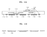
- FIG. 11A is a cross-sectional view of the bioelectric signal measurement apparatus 100 of FIG. 7A taken along the line 11A-11A' in FIG. 7A .
- the bioelectric signal measurement apparatus 100 includes an insulation layer 1110, electrodes 1121-1124 for measuring the electric potential signal ⁇ v of the motion artifact, electrodes 1131 and 1133 for measuring the bioelectric signal, an electrode 1132 for measuring a reference electric potential for the bioelectric signal, an integrated circuit 1140, which, for example, may be a thinned application-specific integrated circuit (ASIC), conductive wires 1150, and various passive devices 1160, such as resistors, or capacitors, or inductors, or any other passive devices known to one of ordinary skill in the art, or any combination thereof.
- ASIC application-specific integrated circuit
- the insulation layer 1110 electrically isolates the electrodes 1131 and 1133 for measuring the bioelectric signal and the electrode 1132 for measuring the reference electric potential for the bioelectric signal from the electrodes 1121-1124 for measuring the electric potential signal ⁇ v of the motion artifact. Also, the insulation layer 1110 prevents electrical coupling or interference between the integrated circuit 1140 and the conductive wires 1150 of the bioelectric signal measurement apparatus 100.
- the electrodes 1121 and 1122 for measuring the electric potential signal ⁇ v of the motion artifact are electrodes having the same electric potential forming the interface E1d, and are arranged at a spacing within the critical distance from the electrode 1131 for measuring the bioelectric signal so the motion artifact measured by the electrodes 1121 and 1122 has almost the same shape on average as the motion artifact measured by the electrode 1131.
- the electrodes 1123 and 1124 for measuring the electric potential signal ⁇ v of the motion artifact are electrodes having the same electric potential for forming the interface E2d, and are arranged at a spacing within the critical distance from the electrode 1133 for measuring the bioelectric signal so the motion artifact measured by the electrodes 1123 and 1124 has almost the same shape on average as the motion artifact measured by the electrode 1133,
- the electrodes 1121-1124 for measuring the electric potential signal ⁇ v of the motion artifact are dry electrodes that directly contact the skin of the testee 110 without the hydrogel 270.
- the dry electrodes may be flat plates formed of a highly conductive metal, such as gold (Au), silver (Ag), platinum (Pt), or any other highly conductive metal know to one of ordinary skill in the art. However, any other type of dry electrode known to one of ordinary skill in the art may be used as the dry electrodes.
- the electrodes 1131 and 1133 for measuring the bioelectric signal are electrodes respectively forming the interfaces E1w and E2w, and are separated from each other by a predetermined distance.
- the electrode 1132 for measuring the reference electric potential for the bioelectric signal is an electrode forming the reference interface E3w, and is separated from the electrodes 1131 and 1133 respectively forming the interfaces E1w and E2w by a predetermined distance so the reference interface E3w is not influenced by the interfaces E1w and E2w.
- the electric potential values measured by the electrodes 1131 and 1133 are differentially amplified to obtain the bioelectric signal.
- the electrodes 1131-1133 are wet electrodes that contact the skin via the hydrogel 270, and may be a flat plate formed of metal coated with a material having a superior conductivity, such as a flat plate formed of silver (Ag) coated with silver chloride (AgCl), or any other type of wet electrode known to one of ordinary skill in the art.
- the electrodes 1131-1133 may be electrodes having sharp protrusions that penetrate the stratum corneum of the skin and make electrical contact points with the epidermis beneath the stratum corneum without the hydrogel 270.
- the integrated circuit 1140 is a semiconductor chip implemented by digital circuits, analog circuits, or both.
- the bias current sources 841 and 842, the differential amplifiers 850 and 860, the modulator 870, and the processor 880 illustrated in FIG. 8 may be located in the integrated circuit 1140.
- the motion artifact extraction unit 160 and the bioelectric signal extraction unit 170 of the bioelectric signal measurement apparatus 100 are implemented by the integrated circuit 1140, the conductive wires 1150, and the various passive devices 1160.
- FIG. 11B is a cross-sectional view of the adhesive sheet 710 of FIG. 7B taken along the line 11B-11B' in FIG. 7B .
- an adhesive sheet 1170 and a hydrogel 1180 are illustrated.
- the adhesive sheet 1170 is a sheet formed of an insulating material having both surfaces coated with an adhesive material, like the adhesive sheet 210 of FIG. 2 , and is used to attach the bioelectric signal measurement apparatus 100 to the skin and keep the bioelectric signal measurement apparatus 100 in contact with the skin. Holes are formed in the adhesive sheet 1170 where the electrodes 1121-1124 of FIG. 11A for measuring the electric potential signal ⁇ v are located, so the electrodes 1121-1124 of FIG.
- the electrodes 1131 and 1133 of FIG. 11A for measuring the bioelectric signal and the electrode 1132 of FIG. 11A for measuring the reference electric potential for the bioelectric signal are wet electrodes
- the electrodes 1131-1133 of FIG. 11A for measuring the bioelectric signal contact the skin via the hydrogel 1180 so that the areas where the electrodes 1131-1133 of FIG. 11A for measuring the bioelectric signal are located are filled with the hydrogel 1180.
- FIG. 12 is a flowchart for explaining an example of a method of measuring bioelectric signals.
- the method of measuring bioelectric signals of FIG. 12 includes operations to be performed using the bioelectric signal measurement apparatus 100 of FIG. 1 .
- the above description of the bioelectric signal measurement apparatus 100 of FIG. 1 is also applicable to the method of measuring bioelectric signals of FIG. 12 .
- the bioelectric signal measurement apparatus 100 applies the current i0 having the frequency fc that does not overlap with the frequency range of the bioelectric signal through the interfaces E1d (130) and E2d (150) that contact the skin of the testee 110.
- the bioelectric signal measurement apparatus 100 detects the electric potential signal ⁇ v modulated at the frequency fc produced by the current i0 applied in operation 1201 through the electrical interfacing with the skin of the testee 110 from the interfaces E1d (130) and E2d (150) having a high contact impedance, and detects the electric potential values of the bioelectric signal through the electrical interfacing with the skin of the testee 110 from the interfaces E1w (120) and E2w (140) having a low contact impedance, that is, a contact impedance that is lower than the contact impedance of the interfaces E1 d (130) and E2d (150) as discussed in detail above.
- the motion artifact extraction unit 160 of the bioelectric signal measurement apparatus 100 differentially amplifies the electric potential signal ⁇ v detected in operation 1202.
- the motion artifact extraction unit 160 demodulates the signal amplified in operation 1203 to recover the original signal to generate a signal proportional to the motion artifact.
- the bioelectric signal extraction unit 170 differentially amplifies the electric potential values of the bioelectric signal detected in operation 1202 to generate the bioelectric signal including the motion artifact.
- the bioelectric signal extraction unit 170 extracts an actual bioelectric signal by removing the motion artifact from the bioelectric signal including the motion artifact generated in operation 1205 using the signal proportional to the motion artifact generated in operation 1204.
- a bioelectric signal of a testee may be accurately measured by extracting a motion artifact included in the bioelectric signal generated by movement of the testee during the measurement of the bioelectric signal, and removing the extracted motion artifact from the bioelectric signal.
- the motion artifact extraction unit 160, the bioelectric signal extraction unit 170, the signal processor 180, the processor 880, the adaptive filter 900, the operator 910, and the processor 1080 described above may be implemented using one or more hardware components, one or more software components, or a combination of one or more hardware components and one or more software components.
- a hardware component may be, for example, a physical device that physically performs one or more operations, but is not limited thereto.
- hardware components include bias current sources, differential amplifiers, demodulators, adaptive filters, operators, integrated circuits, passive devices, low-pass filters, high-pass filters, band-pass filters, analog-to-digital converters, digital-to-analog converters, data storage devices, and processing devices.
- a software component may be implemented, for example, by a processing device controlled by software or instructions to perform one or more operations, but is not limited thereto.
- a computer, controller, or other control device may cause the processing device to run the software or execute the instructions.
- One software component may be implemented by one processing device, or two or more software components may be implemented by one processing device, or one software component may be implemented by two or more processing devices, or two or more software components may be implemented by two or more processing devices.
- a processing device may be implemented using one or more general-purpose or special-purpose computers, such as, for example, a processor, a controller and an arithmetic logic unit, a digital signal processor, a microcomputer, a field-programmable array, a programmable logic unit, a microprocessor, or any other device capable of running software or executing instructions.
- the processing device may run an operating system (OS), and may run one or more software applications that operate under the OS.
- the processing device may access, store, manipulate, process, and create data when running the software or executing the instructions.
- OS operating system
- the singular term "processing device" may be used in the description, but one of ordinary skill in the art will appreciate that a processing device may include multiple processing elements and multiple types of processing elements.
- a processing device may include one or more processors, or one or more processors and one or more controllers.
- different processing configurations are possible, such as parallel processors or multi-core processors.
- a processing device configured to implement a software component to perform an operation A may include a processor programmed to run software or execute instructions to control the processor to perform operation A.
- a processing device configured to implement a software component to perform an operation A, an operation B, and an operation C may have various configurations, such as, for example, a processor configured to implement a software component to perform operations A, B, and C; a first processor configured to implement a software component to perform operation A, and a second processor configured to implement a software component to perform operations B and C; a first processor configured to implement a software component to perform operations A and B, and a second processor configured to implement a software component to perform operation C; a first processor configured to implement a software component to perform operation A, a second processor configured to implement a software component to perform operation B, and a third processor configured to implement a software component to perform operation C; a first processor configured to implement a software component to perform operations A, B, and C, and a second processor configured to implement a software component to perform operations A, B
- Software or instructions for controlling a processing device to implement a software component may include a computer program, a piece of code, an instruction, or some combination thereof, for independently or collectively instructing or configuring the processing device to perform one or more desired operations.
- the software or instructions may include machine code that may be directly executed by the processing device, such as machine code produced by a compiler, and/or higher-level code that may be executed by the processing device using an interpreter.
- the software or instructions and any associated data, data files, and data structures may be embodied permanently or temporarily in any type of machine, component, physical or virtual equipment, computer storage medium or device, or a propagated signal wave capable of providing instructions or data to or being interpreted by the processing device.
- the software or instructions and any associated data, data files, and data structures also may be distributed over network-coupled computer systems so that the software or instructions and any associated data, data files, and data structures are stored and executed in a distributed fashion.
- the software or instructions and any associated data, data files, and data structures may be recorded, stored, or fixed in one or more non-transitory computer-readable storage media.
- a non-transitory computer-readable storage medium may be any data storage device that is capable of storing the software or instructions and any associated data, data files, and data structures so that they can be read by a computer system or processing device.
- Examples of a non-transitory computer-readable storage medium include read-only memory (ROM), random-access memory (RAM), flash memory, CD-ROMs, CD-Rs, CD+Rs, CD-RWs, CD+RWs, DVD-ROMs, DVD-Rs, DVD+Rs, DVD-RWs, DVD+RWs, DVD-RAMs, BD-ROMs, BD-Rs, BD-R LTHs, BD-REs, magnetic tapes, floppy disks, magneto-optical data storage devices, optical data storage devices, hard disks, solid-state disks, or any other non-transitory computer-readable storage medium known to one of ordinary skill in the art.
- ROM read-only memory
- RAM random-access memory
- flash memory CD-ROMs, CD-Rs, CD+Rs, CD-RWs, CD+RWs, DVD-ROMs, DVD-Rs, DVD+Rs, DVD-RWs, DVD+RWs, DVD-RAMs, BD
Landscapes
- Health & Medical Sciences (AREA)
- Life Sciences & Earth Sciences (AREA)
- Engineering & Computer Science (AREA)
- Surgery (AREA)
- General Health & Medical Sciences (AREA)
- Biophysics (AREA)
- Pathology (AREA)
- Veterinary Medicine (AREA)
- Biomedical Technology (AREA)
- Heart & Thoracic Surgery (AREA)
- Medical Informatics (AREA)
- Molecular Biology (AREA)
- Public Health (AREA)
- Animal Behavior & Ethology (AREA)
- Physics & Mathematics (AREA)
- Signal Processing (AREA)
- Artificial Intelligence (AREA)
- Computer Vision & Pattern Recognition (AREA)
- Physiology (AREA)
- Psychiatry (AREA)
- Nuclear Medicine, Radiotherapy & Molecular Imaging (AREA)
- Radiology & Medical Imaging (AREA)
- Measurement And Recording Of Electrical Phenomena And Electrical Characteristics Of The Living Body (AREA)
- Measuring And Recording Apparatus For Diagnosis (AREA)
Applications Claiming Priority (1)
| Application Number | Priority Date | Filing Date | Title |
|---|---|---|---|
| KR1020110085148A KR101832264B1 (ko) | 2011-08-25 | 2011-08-25 | 생체 신호를 측정하는 장치 및 방법 |
Publications (2)
| Publication Number | Publication Date |
|---|---|
| EP2561805A1 EP2561805A1 (en) | 2013-02-27 |
| EP2561805B1 true EP2561805B1 (en) | 2014-05-14 |
Family
ID=47225920
Family Applications (1)
| Application Number | Title | Priority Date | Filing Date |
|---|---|---|---|
| EP12181656.5A Active EP2561805B1 (en) | 2011-08-25 | 2012-08-24 | Apparatus and method for measuring bioelectric signals |
Country Status (5)
| Country | Link |
|---|---|
| US (1) | US9675298B2 (ko) |
| EP (1) | EP2561805B1 (ko) |
| JP (1) | JP6238512B2 (ko) |
| KR (1) | KR101832264B1 (ko) |
| CN (1) | CN102949188B (ko) |
Families Citing this family (26)
| Publication number | Priority date | Publication date | Assignee | Title |
|---|---|---|---|---|
| US10921886B2 (en) * | 2012-06-14 | 2021-02-16 | Medibotics Llc | Circumferential array of electromyographic (EMG) sensors |
| JP2014076117A (ja) * | 2012-10-09 | 2014-05-01 | Nippon Koden Corp | 心電図解析装置および電極セット |
| KR102083559B1 (ko) * | 2013-02-13 | 2020-03-02 | 삼성전자주식회사 | 생체용 전극, 생체 신호 처리 장치 및 생체 신호 처리 방법 |
| EP2886044B1 (en) * | 2013-12-23 | 2019-08-28 | IMEC vzw | System and a method for acquisition of ECG signals with motion artifact reduction. |
| KR102169378B1 (ko) | 2014-02-18 | 2020-10-23 | 삼성전자주식회사 | ECG(electrocardiogram) 센서 및 이의 동작 방법 |
| EP3107447B1 (en) * | 2014-02-19 | 2022-12-07 | Institut National De La Recherche Scientifique (INRS) | Method and system for evaluating a noise level of a biosignal |
| AU2014414868B2 (en) * | 2014-12-23 | 2019-12-05 | Nitto Denko Corporation | Device and method for removal of artifacts in physiological measurements |
| CN107205683B (zh) * | 2015-01-14 | 2021-11-02 | 创心有限公司 | 用于监测生物体的内部电阻抗的方法和系统 |
| CN106456037B (zh) * | 2015-05-11 | 2019-07-12 | 路仁技术有限公司 | 生物信号测量装置 |
| CN104917471B (zh) * | 2015-06-29 | 2017-09-19 | 浙江大学 | 一种生理信号采集放大电路 |
| US11696715B2 (en) | 2015-07-10 | 2023-07-11 | Bodyport Inc. | Cardiovascular signal acquisition, fusion, and noise mitigation |
| KR102556007B1 (ko) | 2015-10-07 | 2023-07-17 | 삼성전자주식회사 | 생체신호 측정장치 및 방법 |
| CN105640536B (zh) * | 2016-03-17 | 2018-06-26 | 镇江市高等专科学校 | 可减少温度误差的生物体表电信号探测方法 |
| CN105640535B (zh) * | 2016-03-17 | 2018-05-08 | 镇江市高等专科学校 | 生物体表电信号探测电极阵列 |
| CN107049299B (zh) * | 2017-04-06 | 2019-12-06 | 河北大学 | 一种抗干扰心电检测系统与检测方法 |
| WO2019045526A1 (ko) * | 2017-08-31 | 2019-03-07 | 신주니어데이비드승준 | 신축성 저항 소자를 이용한 자세 모니터링 장치, 이를 이용한 자세 모니터링 방법 및 시스템 |
| CN111315295A (zh) * | 2017-08-31 | 2020-06-19 | 申承埈 | 利用伸缩性电阻元件的姿势监视装置、利用该装置的姿势监视方法及系统 |
| CN107731301A (zh) * | 2017-10-30 | 2018-02-23 | 无锡中盛医疗设备有限公司 | 一种基于对生物电信号分析的疾病诊断系统及方法 |
| US11172875B2 (en) * | 2018-01-25 | 2021-11-16 | Cardiac Pacemakers, Inc. | Systems and methods for dynamic respiration sensing |
| CN108567423A (zh) * | 2018-03-07 | 2018-09-25 | 南京宽诚科技有限公司 | 一种生物电信号的检测方法及装置 |
| KR102101809B1 (ko) | 2018-09-20 | 2020-04-23 | 링크페이스 주식회사 | 수면 및 각성 유도 장치 |
| CA3116846A1 (en) * | 2018-10-17 | 2020-04-23 | Bodyport Inc. | Cardiovascular signal acquisition, fusion, and noise mitigation |
| KR102171566B1 (ko) | 2018-11-15 | 2020-10-29 | 링크페이스 주식회사 | 생체 신호 측정 방법, 장치 및 컴퓨터 프로그램 |
| CN110449694A (zh) * | 2019-08-20 | 2019-11-15 | 华能国际电力股份有限公司 | 一种tig焊弧长闭环控制电路 |
| KR102353059B1 (ko) * | 2020-04-13 | 2022-01-20 | 주식회사 아이센스 | 생체정보의 측정장치 |
| KR20220045278A (ko) | 2020-10-05 | 2022-04-12 | (주)투비시스 | 생체정보를 이용한 건강관리 서비스 제공 서버, 방법 및 프로그램 |
Family Cites Families (33)
| Publication number | Priority date | Publication date | Assignee | Title |
|---|---|---|---|---|
| US4004578A (en) | 1974-09-10 | 1977-01-25 | Salve S.A. | Expendable electro-cardiograph electrode |
| US4837049A (en) * | 1986-06-17 | 1989-06-06 | Alfred E. Mann Foundation For Scientific Research | Method of making an electrode array |
| US4969468A (en) | 1986-06-17 | 1990-11-13 | Alfred E. Mann Foundation For Scientific Research | Electrode array for use in connection with a living body and method of manufacture |
| US5206602A (en) * | 1992-04-30 | 1993-04-27 | Hewlett-Packard Company | Biomedical amplifier circuit |
| US5309909A (en) * | 1992-05-22 | 1994-05-10 | Physio-Control Corporation | Combined skin preparation and monitoring electrode |
| US5713367A (en) * | 1994-01-26 | 1998-02-03 | Cambridge Heart, Inc. | Measuring and assessing cardiac electrical stability |
| EP0746229B1 (en) | 1994-01-26 | 2003-09-10 | Cambridge Heart, Inc. | Apparatus for measuring and assessing cardiac electrical stability |
| SE9601387D0 (sv) * | 1996-04-12 | 1996-04-12 | Siemens Elema Ab | Anordning för övervakning av för upptagning av fysiologiska mätsignaler avsedda mätelektroder samt deras tilledningar |
| US5749369A (en) * | 1996-08-09 | 1998-05-12 | R.S. Medical Monitoring Ltd. | Method and device for stable impedance plethysmography |
| KR100321261B1 (ko) | 1999-01-11 | 2002-01-19 | 차기철 | 심박출량과 심전도를 모니터링하기 위한 전극 설치 방법 및 이를 이용한 장치 |
| US6807438B1 (en) * | 1999-08-26 | 2004-10-19 | Riccardo Brun Del Re | Electric field sensor |
| US20020038092A1 (en) * | 2000-08-10 | 2002-03-28 | Stanaland Thomas G. | Capacitively coupled electrode system for sensing voltage potentials at the surface of tissue |
| US6690959B2 (en) * | 2000-09-01 | 2004-02-10 | Medtronic, Inc. | Skin-mounted electrodes with nano spikes |
| JP4840952B2 (ja) | 2000-09-19 | 2011-12-21 | 株式会社フィジオン | 生体電気インピーダンス計測方法及び計測装置、並びに該計測装置を用いた健康指針管理アドバイス装置 |
| WO2002065904A1 (en) * | 2001-02-23 | 2002-08-29 | Cordless Antistatic Research Inc. | Enhanced pickup bio-electrode |
| US6912414B2 (en) * | 2002-01-29 | 2005-06-28 | Southwest Research Institute | Electrode systems and methods for reducing motion artifact |
| DE60333225D1 (de) * | 2002-12-10 | 2010-08-12 | Philips Intellectual Property | Tragbare vorrichtung für die bioelektrische interaktion mit bewegungsartefakt-korrekturmitteln |
| US6961601B2 (en) * | 2003-06-11 | 2005-11-01 | Quantum Applied Science & Research, Inc. | Sensor system for measuring biopotentials |
| KR20050072965A (ko) | 2004-01-08 | 2005-07-13 | 림스테크널러지주식회사 | 생체신호 검출용 건식 능동 센서모듈 |
| WO2005077260A1 (en) | 2004-02-12 | 2005-08-25 | Biopeak Corporation | Non-invasive method and apparatus for determining a physiological parameter |
| WO2006007573A1 (en) * | 2004-07-01 | 2006-01-19 | Quantum Applied Science & Research, Inc. | A sensor system for measuring an electric potential signal of an object |
| US7245961B2 (en) * | 2004-07-19 | 2007-07-17 | Hewlett-Packard Development Company, L.P. | ECG electrode characterization and compensation |
| KR100659511B1 (ko) | 2004-10-18 | 2006-12-20 | 학교법인연세대학교 | 패치형 무선 태아 감시장치 |
| WO2006111876A1 (en) | 2005-04-19 | 2006-10-26 | Philips Intellectual Property & Standards Gmbh | System and method for measuring bioelectrical signals of a user |
| KR100825888B1 (ko) | 2005-10-05 | 2008-04-28 | 삼성전자주식회사 | 전극 동잡음 보상 회로 및 전극 동잡음 보상 방법 |
| US20070238945A1 (en) | 2006-03-22 | 2007-10-11 | Emir Delic | Electrode Headset |
| KR100866547B1 (ko) | 2007-02-09 | 2008-11-03 | 연세대학교 산학협력단 | 심전도 잡음 제거 수단을 구비한 뇌전도 검사 장치 및 방법 |
| CN101778597A (zh) * | 2007-08-20 | 2010-07-14 | 皇家飞利浦电子股份有限公司 | 用于测量身体参数的方法 |
| EP2203114B1 (de) | 2007-09-07 | 2011-11-16 | Flore, Ingo | Medizinische messvorrichtung zur bioelektrischen impedanzmessung |
| JP2012500703A (ja) * | 2008-08-29 | 2012-01-12 | コーニンクレッカ フィリップス エレクトロニクス エヌ ヴィ | 電気生理学信号の容量測定における運動アーチファクトの補償 |
| EP2236078A1 (en) * | 2009-04-02 | 2010-10-06 | Koninklijke Philips Electronics N.V. | Processing a bio-physiological signal |
| US20100331659A1 (en) | 2009-06-29 | 2010-12-30 | Sheraton Sr David A | Low artifact defibrillation electrode |
| WO2011007292A1 (en) | 2009-07-13 | 2011-01-20 | Koninklijke Philips Electronics N.V. | Electro-physiological measurement with reduced motion artifacts |
-
2011
- 2011-08-25 KR KR1020110085148A patent/KR101832264B1/ko active IP Right Grant
-
2012
- 2012-08-23 US US13/592,639 patent/US9675298B2/en active Active
- 2012-08-24 EP EP12181656.5A patent/EP2561805B1/en active Active
- 2012-08-24 CN CN201210304313.7A patent/CN102949188B/zh active Active
- 2012-08-27 JP JP2012187001A patent/JP6238512B2/ja active Active
Also Published As
| Publication number | Publication date |
|---|---|
| US20130053675A1 (en) | 2013-02-28 |
| CN102949188B (zh) | 2016-09-28 |
| JP2013043095A (ja) | 2013-03-04 |
| KR20130022542A (ko) | 2013-03-07 |
| KR101832264B1 (ko) | 2018-04-13 |
| JP6238512B2 (ja) | 2017-11-29 |
| US9675298B2 (en) | 2017-06-13 |
| CN102949188A (zh) | 2013-03-06 |
| EP2561805A1 (en) | 2013-02-27 |
Similar Documents
| Publication | Publication Date | Title |
|---|---|---|
| EP2561805B1 (en) | Apparatus and method for measuring bioelectric signals | |
| KR101736978B1 (ko) | 생체 신호를 측정하는 장치 및 방법 | |
| US8626259B2 (en) | Biomedical sensors usable on un-prepared contact surfaces | |
| US8860504B2 (en) | Method and apparatus for measuring biological signal | |
| EP2896360B1 (en) | Apparatus and method of measuring bio impedance | |
| CN110811544B (zh) | 使用振荡器对电极-组织接触进行的估计 | |
| EP2843833B1 (en) | Reconfigurable measuring apparatus and method for controlling apparatus | |
| US20140081114A1 (en) | Method and apparatus for measuring biopotential and mapping ephaptic coupling employing a catheter with mosfet sensor array | |
| US9936889B2 (en) | Apparatus and method of controlling threshold for detecting peaks of physiological signals | |
| WO2011056626A1 (en) | Biomedical electrode | |
| KR102083559B1 (ko) | 생체용 전극, 생체 신호 처리 장치 및 생체 신호 처리 방법 | |
| EP3209197B1 (en) | Simultaneous impedance testing method and apparatus | |
| RU2732344C2 (ru) | Система, регистратор и способ поверхностной электромиографии | |
| Kuronen | Epic Sensors in electrocardiogram measurement | |
| Svärd et al. | Design and evaluation of a capacitively coupled sensor readout circuit, toward contact-less ECG and EEG | |
| JP4189551B2 (ja) | 心室容積連続自動測定装置 | |
| Sweeney et al. | A simple bio-signals quality measure for in-home monitoring | |
| JP3909710B2 (ja) | 心室容積測定装置及び心室容積測定方法 | |
| Garcia-Casado et al. | Opened-Ring Electrode Array for Enhanced Non-invasive Monitoring of Bioelectrical Signals: Application to Surface EEnG Recording | |
| KR101041943B1 (ko) | 전기적 비접촉 심전도를 이용한 체표전위 측정장치 | |
| JP2023054778A (ja) | 損傷電流の存在下での電気生理学的マッピング | |
| JP2021094381A (ja) | ユニポーラ信号及びバイポーラ信号を使用した心室活動の検出 | |
| Ravariu et al. | Manufacturing of capacitive electrodes on Si-substrate for electrophysiological applications | |
| JP2023514508A (ja) | 電極対皮膚結合の推定を伴う容量結合による電気生理学的検出のための検出システム及び方法 |
Legal Events
| Date | Code | Title | Description |
|---|---|---|---|
| PUAI | Public reference made under article 153(3) epc to a published international application that has entered the european phase |
Free format text: ORIGINAL CODE: 0009012 |
|
| AK | Designated contracting states |
Kind code of ref document: A1 Designated state(s): AL AT BE BG CH CY CZ DE DK EE ES FI FR GB GR HR HU IE IS IT LI LT LU LV MC MK MT NL NO PL PT RO RS SE SI SK SM TR |
|
| AX | Request for extension of the european patent |
Extension state: BA ME |
|
| 17P | Request for examination filed |
Effective date: 20130820 |
|
| RBV | Designated contracting states (corrected) |
Designated state(s): AL AT BE BG CH CY CZ DE DK EE ES FI FR GB GR HR HU IE IS IT LI LT LU LV MC MK MT NL NO PL PT RO RS SE SI SK SM TR |
|
| GRAP | Despatch of communication of intention to grant a patent |
Free format text: ORIGINAL CODE: EPIDOSNIGR1 |
|
| INTG | Intention to grant announced |
Effective date: 20140106 |
|
| GRAS | Grant fee paid |
Free format text: ORIGINAL CODE: EPIDOSNIGR3 |
|
| GRAA | (expected) grant |
Free format text: ORIGINAL CODE: 0009210 |
|
| AK | Designated contracting states |
Kind code of ref document: B1 Designated state(s): AL AT BE BG CH CY CZ DE DK EE ES FI FR GB GR HR HU IE IS IT LI LT LU LV MC MK MT NL NO PL PT RO RS SE SI SK SM TR |
|
| REG | Reference to a national code |
Ref country code: GB Ref legal event code: FG4D |
|
| REG | Reference to a national code |
Ref country code: AT Ref legal event code: REF Ref document number: 667622 Country of ref document: AT Kind code of ref document: T Effective date: 20140615 |
|
| REG | Reference to a national code |
Ref country code: IE Ref legal event code: FG4D |
|
| REG | Reference to a national code |
Ref country code: DE Ref legal event code: R096 Ref document number: 602012001737 Country of ref document: DE Effective date: 20140626 |
|
| REG | Reference to a national code |
Ref country code: NL Ref legal event code: T3 |
|
| REG | Reference to a national code |
Ref country code: AT Ref legal event code: MK05 Ref document number: 667622 Country of ref document: AT Kind code of ref document: T Effective date: 20140514 |
|
| REG | Reference to a national code |
Ref country code: LT Ref legal event code: MG4D |
|
| PG25 | Lapsed in a contracting state [announced via postgrant information from national office to epo] |
Ref country code: IS Free format text: LAPSE BECAUSE OF FAILURE TO SUBMIT A TRANSLATION OF THE DESCRIPTION OR TO PAY THE FEE WITHIN THE PRESCRIBED TIME-LIMIT Effective date: 20140914 Ref country code: GR Free format text: LAPSE BECAUSE OF FAILURE TO SUBMIT A TRANSLATION OF THE DESCRIPTION OR TO PAY THE FEE WITHIN THE PRESCRIBED TIME-LIMIT Effective date: 20140815 Ref country code: FI Free format text: LAPSE BECAUSE OF FAILURE TO SUBMIT A TRANSLATION OF THE DESCRIPTION OR TO PAY THE FEE WITHIN THE PRESCRIBED TIME-LIMIT Effective date: 20140514 Ref country code: CY Free format text: LAPSE BECAUSE OF FAILURE TO SUBMIT A TRANSLATION OF THE DESCRIPTION OR TO PAY THE FEE WITHIN THE PRESCRIBED TIME-LIMIT Effective date: 20140514 Ref country code: NO Free format text: LAPSE BECAUSE OF FAILURE TO SUBMIT A TRANSLATION OF THE DESCRIPTION OR TO PAY THE FEE WITHIN THE PRESCRIBED TIME-LIMIT Effective date: 20140814 Ref country code: LT Free format text: LAPSE BECAUSE OF FAILURE TO SUBMIT A TRANSLATION OF THE DESCRIPTION OR TO PAY THE FEE WITHIN THE PRESCRIBED TIME-LIMIT Effective date: 20140514 |
|
| PG25 | Lapsed in a contracting state [announced via postgrant information from national office to epo] |
Ref country code: SE Free format text: LAPSE BECAUSE OF FAILURE TO SUBMIT A TRANSLATION OF THE DESCRIPTION OR TO PAY THE FEE WITHIN THE PRESCRIBED TIME-LIMIT Effective date: 20140514 Ref country code: HR Free format text: LAPSE BECAUSE OF FAILURE TO SUBMIT A TRANSLATION OF THE DESCRIPTION OR TO PAY THE FEE WITHIN THE PRESCRIBED TIME-LIMIT Effective date: 20140514 Ref country code: LV Free format text: LAPSE BECAUSE OF FAILURE TO SUBMIT A TRANSLATION OF THE DESCRIPTION OR TO PAY THE FEE WITHIN THE PRESCRIBED TIME-LIMIT Effective date: 20140514 Ref country code: ES Free format text: LAPSE BECAUSE OF FAILURE TO SUBMIT A TRANSLATION OF THE DESCRIPTION OR TO PAY THE FEE WITHIN THE PRESCRIBED TIME-LIMIT Effective date: 20140514 Ref country code: RS Free format text: LAPSE BECAUSE OF FAILURE TO SUBMIT A TRANSLATION OF THE DESCRIPTION OR TO PAY THE FEE WITHIN THE PRESCRIBED TIME-LIMIT Effective date: 20140514 Ref country code: PL Free format text: LAPSE BECAUSE OF FAILURE TO SUBMIT A TRANSLATION OF THE DESCRIPTION OR TO PAY THE FEE WITHIN THE PRESCRIBED TIME-LIMIT Effective date: 20140514 Ref country code: AT Free format text: LAPSE BECAUSE OF FAILURE TO SUBMIT A TRANSLATION OF THE DESCRIPTION OR TO PAY THE FEE WITHIN THE PRESCRIBED TIME-LIMIT Effective date: 20140514 |
|
| PG25 | Lapsed in a contracting state [announced via postgrant information from national office to epo] |
Ref country code: PT Free format text: LAPSE BECAUSE OF FAILURE TO SUBMIT A TRANSLATION OF THE DESCRIPTION OR TO PAY THE FEE WITHIN THE PRESCRIBED TIME-LIMIT Effective date: 20140915 |
|
| PG25 | Lapsed in a contracting state [announced via postgrant information from national office to epo] |
Ref country code: DK Free format text: LAPSE BECAUSE OF FAILURE TO SUBMIT A TRANSLATION OF THE DESCRIPTION OR TO PAY THE FEE WITHIN THE PRESCRIBED TIME-LIMIT Effective date: 20140514 Ref country code: EE Free format text: LAPSE BECAUSE OF FAILURE TO SUBMIT A TRANSLATION OF THE DESCRIPTION OR TO PAY THE FEE WITHIN THE PRESCRIBED TIME-LIMIT Effective date: 20140514 Ref country code: BE Free format text: LAPSE BECAUSE OF FAILURE TO SUBMIT A TRANSLATION OF THE DESCRIPTION OR TO PAY THE FEE WITHIN THE PRESCRIBED TIME-LIMIT Effective date: 20140514 Ref country code: CZ Free format text: LAPSE BECAUSE OF FAILURE TO SUBMIT A TRANSLATION OF THE DESCRIPTION OR TO PAY THE FEE WITHIN THE PRESCRIBED TIME-LIMIT Effective date: 20140514 Ref country code: RO Free format text: LAPSE BECAUSE OF FAILURE TO SUBMIT A TRANSLATION OF THE DESCRIPTION OR TO PAY THE FEE WITHIN THE PRESCRIBED TIME-LIMIT Effective date: 20140514 Ref country code: SK Free format text: LAPSE BECAUSE OF FAILURE TO SUBMIT A TRANSLATION OF THE DESCRIPTION OR TO PAY THE FEE WITHIN THE PRESCRIBED TIME-LIMIT Effective date: 20140514 |
|
| REG | Reference to a national code |
Ref country code: DE Ref legal event code: R097 Ref document number: 602012001737 Country of ref document: DE |
|
| PLBE | No opposition filed within time limit |
Free format text: ORIGINAL CODE: 0009261 |
|
| STAA | Information on the status of an ep patent application or granted ep patent |
Free format text: STATUS: NO OPPOSITION FILED WITHIN TIME LIMIT |
|
| PG25 | Lapsed in a contracting state [announced via postgrant information from national office to epo] |
Ref country code: LU Free format text: LAPSE BECAUSE OF FAILURE TO SUBMIT A TRANSLATION OF THE DESCRIPTION OR TO PAY THE FEE WITHIN THE PRESCRIBED TIME-LIMIT Effective date: 20140824 Ref country code: MC Free format text: LAPSE BECAUSE OF FAILURE TO SUBMIT A TRANSLATION OF THE DESCRIPTION OR TO PAY THE FEE WITHIN THE PRESCRIBED TIME-LIMIT Effective date: 20140514 |
|
| 26N | No opposition filed |
Effective date: 20150217 |
|
| PG25 | Lapsed in a contracting state [announced via postgrant information from national office to epo] |
Ref country code: IT Free format text: LAPSE BECAUSE OF FAILURE TO SUBMIT A TRANSLATION OF THE DESCRIPTION OR TO PAY THE FEE WITHIN THE PRESCRIBED TIME-LIMIT Effective date: 20140514 Ref country code: BE Free format text: LAPSE BECAUSE OF FAILURE TO SUBMIT A TRANSLATION OF THE DESCRIPTION OR TO PAY THE FEE WITHIN THE PRESCRIBED TIME-LIMIT Effective date: 20140831 |
|
| REG | Reference to a national code |
Ref country code: IE Ref legal event code: MM4A |
|
| REG | Reference to a national code |
Ref country code: DE Ref legal event code: R097 Ref document number: 602012001737 Country of ref document: DE Effective date: 20150217 |
|
| PG25 | Lapsed in a contracting state [announced via postgrant information from national office to epo] |
Ref country code: SI Free format text: LAPSE BECAUSE OF FAILURE TO SUBMIT A TRANSLATION OF THE DESCRIPTION OR TO PAY THE FEE WITHIN THE PRESCRIBED TIME-LIMIT Effective date: 20140514 |
|
| PG25 | Lapsed in a contracting state [announced via postgrant information from national office to epo] |
Ref country code: IE Free format text: LAPSE BECAUSE OF NON-PAYMENT OF DUE FEES Effective date: 20140824 |
|
| REG | Reference to a national code |
Ref country code: CH Ref legal event code: PL |
|
| PG25 | Lapsed in a contracting state [announced via postgrant information from national office to epo] |
Ref country code: CH Free format text: LAPSE BECAUSE OF NON-PAYMENT OF DUE FEES Effective date: 20150831 Ref country code: LI Free format text: LAPSE BECAUSE OF NON-PAYMENT OF DUE FEES Effective date: 20150831 |
|
| PG25 | Lapsed in a contracting state [announced via postgrant information from national office to epo] |
Ref country code: SM Free format text: LAPSE BECAUSE OF FAILURE TO SUBMIT A TRANSLATION OF THE DESCRIPTION OR TO PAY THE FEE WITHIN THE PRESCRIBED TIME-LIMIT Effective date: 20140514 |
|
| PG25 | Lapsed in a contracting state [announced via postgrant information from national office to epo] |
Ref country code: BG Free format text: LAPSE BECAUSE OF FAILURE TO SUBMIT A TRANSLATION OF THE DESCRIPTION OR TO PAY THE FEE WITHIN THE PRESCRIBED TIME-LIMIT Effective date: 20140514 Ref country code: MT Free format text: LAPSE BECAUSE OF FAILURE TO SUBMIT A TRANSLATION OF THE DESCRIPTION OR TO PAY THE FEE WITHIN THE PRESCRIBED TIME-LIMIT Effective date: 20140514 |
|
| PG25 | Lapsed in a contracting state [announced via postgrant information from national office to epo] |
Ref country code: HU Free format text: LAPSE BECAUSE OF FAILURE TO SUBMIT A TRANSLATION OF THE DESCRIPTION OR TO PAY THE FEE WITHIN THE PRESCRIBED TIME-LIMIT; INVALID AB INITIO Effective date: 20120824 Ref country code: TR Free format text: LAPSE BECAUSE OF FAILURE TO SUBMIT A TRANSLATION OF THE DESCRIPTION OR TO PAY THE FEE WITHIN THE PRESCRIBED TIME-LIMIT Effective date: 20140514 |
|
| REG | Reference to a national code |
Ref country code: FR Ref legal event code: PLFP Year of fee payment: 5 |
|
| REG | Reference to a national code |
Ref country code: FR Ref legal event code: PLFP Year of fee payment: 6 |
|
| PG25 | Lapsed in a contracting state [announced via postgrant information from national office to epo] |
Ref country code: MK Free format text: LAPSE BECAUSE OF FAILURE TO SUBMIT A TRANSLATION OF THE DESCRIPTION OR TO PAY THE FEE WITHIN THE PRESCRIBED TIME-LIMIT Effective date: 20140514 |
|
| REG | Reference to a national code |
Ref country code: FR Ref legal event code: PLFP Year of fee payment: 7 |
|
| PG25 | Lapsed in a contracting state [announced via postgrant information from national office to epo] |
Ref country code: AL Free format text: LAPSE BECAUSE OF FAILURE TO SUBMIT A TRANSLATION OF THE DESCRIPTION OR TO PAY THE FEE WITHIN THE PRESCRIBED TIME-LIMIT Effective date: 20140514 |
|
| REG | Reference to a national code |
Ref country code: DE Ref legal event code: R079 Ref document number: 602012001737 Country of ref document: DE Free format text: PREVIOUS MAIN CLASS: A61B0005040000 Ipc: A61B0005240000 |
|
| P01 | Opt-out of the competence of the unified patent court (upc) registered |
Effective date: 20230520 |
|
| PGFP | Annual fee paid to national office [announced via postgrant information from national office to epo] |
Ref country code: NL Payment date: 20230728 Year of fee payment: 12 |
|
| PGFP | Annual fee paid to national office [announced via postgrant information from national office to epo] |
Ref country code: GB Payment date: 20230720 Year of fee payment: 12 |
|
| PGFP | Annual fee paid to national office [announced via postgrant information from national office to epo] |
Ref country code: FR Payment date: 20230721 Year of fee payment: 12 Ref country code: DE Payment date: 20230718 Year of fee payment: 12 |