EP2560136A1 - Procédé, système et produit de programme informatique pour événements de demande de planification - Google Patents
Procédé, système et produit de programme informatique pour événements de demande de planification Download PDFInfo
- Publication number
- EP2560136A1 EP2560136A1 EP12180278A EP12180278A EP2560136A1 EP 2560136 A1 EP2560136 A1 EP 2560136A1 EP 12180278 A EP12180278 A EP 12180278A EP 12180278 A EP12180278 A EP 12180278A EP 2560136 A1 EP2560136 A1 EP 2560136A1
- Authority
- EP
- European Patent Office
- Prior art keywords
- time period
- over
- power generation
- power
- estimated
- Prior art date
- Legal status (The legal status is an assumption and is not a legal conclusion. Google has not performed a legal analysis and makes no representation as to the accuracy of the status listed.)
- Ceased
Links
Images


Classifications
-
- G—PHYSICS
- G06—COMPUTING; CALCULATING OR COUNTING
- G06Q—INFORMATION AND COMMUNICATION TECHNOLOGY [ICT] SPECIALLY ADAPTED FOR ADMINISTRATIVE, COMMERCIAL, FINANCIAL, MANAGERIAL OR SUPERVISORY PURPOSES; SYSTEMS OR METHODS SPECIALLY ADAPTED FOR ADMINISTRATIVE, COMMERCIAL, FINANCIAL, MANAGERIAL OR SUPERVISORY PURPOSES, NOT OTHERWISE PROVIDED FOR
- G06Q10/00—Administration; Management
- G06Q10/06—Resources, workflows, human or project management; Enterprise or organisation planning; Enterprise or organisation modelling
Definitions
- DRMSs demand response management systems
- the utility may be allowed to turn off certain appliances such a HVAC, an electric water heater, stove, refrigerator and the like within a customer's residence during periods of high demand.
- commercial customers may allow the utility to cut off all or a part of the electrical service during periods of high demand.
- the utility's authorization to reduce or completely cut-off a consumer's electrical service is referred to as a demand event.
- These demand events are usually limited in the number that can occur oven a given time period (e.g., no more than five per month), and sometimes are limited in duration (e.g., cannot cut off HVAC for longer than two hours). Consumers can be encouraged to enroll in such programs, despite the possible inconvenience, by the utility offering a preferred rate for electricity or through other incentives.
- Disclosed and described herein are embodiments of systems, methods and computer program for scheduling demand events over a time period based on differences between the estimated power availability and the estimated power consumption at various points during the time period.
- One embodiment of a method comprises establishing a defined time period, estimating power availability over the time period, estimating power consumption over the time period, and scheduling, using a computing device, demand events over the time period based on differences between the estimated power availability and the estimated power consumption at various points during the time period.
- systems are described.
- a system comprises a memory and a processor operably connected with the memory.
- the processor is configured to establish a defined time period; estimate power availability over the time period; estimate power consumption over the time period; and schedule demand events stored in the memory over the time period based on differences between the estimated power availability and the estimated power consumption at various points during the time period.
- One embodiment of a computer program product comprises computer-executable code on a non-transitory computer-readable medium.
- the computer-executable code is for performing the steps of establishing a defined time period; estimating power availability over the time period, wherein estimating power availability over the time period comprises estimating internal power generation controlled by a utility and estimating acquired power availability that can be purchased from sources not controlled by the utility over the time period, and wherein the internal power generation controlled by the utility includes fixed power generation and variable power generation; estimating power consumption over the time period; and scheduling, using a computing device, demand events over the time period based on differences between the estimated power availability and the estimated power consumption at various points during the time period.
- FIG. 1 is a single-line block diagram of a section of an example utility distribution system such as, for example, an electric distribution system.
- a utility service is delivered by a utility provider 100 to various loads L 1 -L n 102 through a distribution system 104.
- the utility service provided can be electric power.
- the distribution system 104 can be comprised of single-phase and/or poly-phase components and be of varying voltage levels. Consumption and demand by the loads 102 can be measured at the load locations by meters M 1 -M n 106.
- the meters 106 can be single-phase or poly-phase electric meters, as known to one of ordinary skill in the art, depending upon the load 102.
- the load can be single-phase and therefore the meter 106 can be single phase.
- Single-phase loads can be connected to different phases (e.g., phase A, phase B or phase C) of the distribution system 104.
- the load 102 can be a poly-phase load such as a three-phase load and the meter 106 can be a three-phase meter that meters the three phases serving the load 102.
- the electric meter 106 is a smart meter as described herein and as known to one of ordinary skill in the art.
- the specification will refer to the meter 106 as a "meter,” “electric meter,” and/or “smart meter,” where the terms can be used interchangeably.
- a smart meter is the GE 1210+c meter as available from General Electric Company (“GE”) (Schenectady, NY).
- GE General Electric Company
- Another non-limiting example of a smart meter is the GE SM3000 meter as also available from GE. While consumption or demand information is used by the utility provider 100 primarily for billing the consumer, it also can be used for other purposes including planning and profiling the utility distribution system.
- utility providers 100 desire to electronically communicate with the meters 106 for numerous purposes including scheduling disconnection or connection of utility services to the loads 102, automatic meter reading (AMR), load shedding and load control, automatic distribution and smart-grid applications, outage reporting, providing additional services such as Internet, video, and audio, etc.
- AMR automatic meter reading
- the meters 106 can be configured to communicate with one or more computing devices 108 through a communications network 110, which can be wired, wireless or a combination of wired and wireless, as known to one of ordinary skill in the art.
- the network 110 is an advanced metering infrastructure (AMI) network.
- AMI advanced metering infrastructure
- AMI refers to systems that measure, collect and analyze energy usage, and interact with advanced devices such as electricity meters, gas meters, water meters, and the like through various communication media either on request (on-demand) or on pre-defined schedules.
- This infrastructure includes hardware, software, communications, consumer energy displays and controllers, customer associated systems, meter data management (MDM) software, supplier and network distribution business systems, and the like.
- MDM meter data management
- the network 110 between the measurement devices (e.g., meters 106) and business systems allows collection and distribution of information to customers, suppliers, utility companies and service providers. This enables these businesses to either participate in, or provide, demand response solutions, products and services.
- the system assists a change in energy usage from their normal consumption patterns, either in response to changes in price or as incentives designed to encourage lower energy usage use at times of peak-demand periods or higher wholesale prices or during periods of low operational systems reliability.
- the network 110 comprises at least a portion of a smart grid network.
- the network 110 utilizes one or more of one or more of a WPAN (e.g., ZigBee, Bluetooth), LAN/WLAN (e.g., 802.11n, microwave, laser, etc.), WMAN (e.g., WiMAX, etc.), WAN/WWAN (e.g., UMTS, GPRS, EDGE, CDMA, GSM, CDPD, Mobitex, HSDPA, HSUPA, 3G, etc.), RS232, USB, Firewire, Ethernet, wireless USB, cellular, OpenHAN, power line carrier (PLC), broadband over power lines (BPL), and the like.
- WPAN e.g., ZigBee, Bluetooth
- LAN/WLAN e.g., 802.11n, microwave, laser, etc.
- WMAN e.g., WiMAX, etc.
- WAN/WWAN e.g., UMTS, GPRS, EDGE, CDMA, GSM, CDPD, Mobitex, H
- the utility 100 desires to communicate with one or more electrical devices 102 at a metered location.
- the network 110 can be used by the utility to communicate with the one or more electrical devices 102.
- a utility may desire to control operational characteristics of loads (e.g. electrical devices) 102 by use of a demand response management system (DRMS).
- DRMS demand response management system
- An example DRMS can be implemented through the use of dedicated control systems to shed loads in response to a request by a utility 100 or based upon market price conditions. Services (e.g., lights, machines, air conditioning, etc.) can be reduced according to a preplanned load prioritization scheme during the critical time frames.
- a DRMS can control or affect the operational characteristics of one or more electrical devices 102 found at a metered location.
- Such electrical devices can include, for example, one or more of a heating, ventilation and air conditioning (HVAC) unit, a water heater, lighting, a dish washer, a refrigerator, a washing machine, a dryer, an electric stove or oven, a microwave oven, and the like.
- HVAC heating, ventilation and air conditioning
- the utility 100 can communicate with the electrical devices 102 by use of network 110 that can comprise all or part of a DRMS, an AMI (as described herein), a smart-grid implementation, an Internet connection, or combinations thereof.
- the network 110 media can be wired (including fiber optic), wireless, or combinations thereof.
- the network 110 communicates with a meter 106, such as a smart meter, which in turn communicates 112 either wirelessly or through a wired connection with the one or more electrical devices 102 at the metered location.
- the network 110 can communicate directly with the one or more electrical devices 102 using, for example, the Internet, cellular telephone, wired telephone connections, wired cable television connections, and the like.
- Computing device 108 can be used to control utility 100 functions such as meter reading, operation of the DRMS, and the like.
- computing device 108 may be connected with other systems 114 through one or more other networks 116.
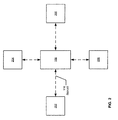
- FIG. 2 is an overview block diagram of a system that can be used to implement embodiments of the present invention.
- computing device 108 which can be used to implement aspects of the present invention, can be interconnected with or also be used to implement all or parts of one or more other systems such as, for example, a demand response management system (DRMS) 202, a load forecasting and profiling system 204 that includes individual customer usage information as well as projected usage information over a specified time period, a power generation and acquisition system 206 that estimates electrical energy that can be generated by utility-controlled resources (both fixed and variable generation), and electrical energy that can be acquired from sources not controlled by the utility over a specified time period, and a weather forecasting system 208 that provides data regarding anticipated weather events over a specified time period.
- DRMS demand response management system
- load forecasting and profiling system 204 that includes individual customer usage information as well as projected usage information over a specified time period
- power generation and acquisition system 206 that estimates electrical energy that can be generated by utility-controlled resources (both fixed and variable generation), and electrical
- Such systems can be interconnected with computing device 108 through one or more networks 116, which can be comprised of wired (including fiber optic) or wireless media, and combinations thereof, and using any of a number of present or future-developed protocols.
- Information can be passed to and from computing device 108 and the various systems 202, 204, 206, 208. In other aspects, information from one or more of systems 202, 204, 206, 208 can be manually input into computing device 108 in order to facilitate implementation of embodiments of the present invention.
- computing device 108 can be interconnected with various utility devices such as meters 106 through network 110, which can be an AMI network, as described herein.
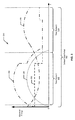
- FIG. 3 is an example graph 300 illustrating a defined time period 302 and various estimated demand and availability curves over the time period 302.
- the time period 302 is initially not fixed and can be set as desired.
- the defined time period 302 can comprise establishing a time period of one hour, one day, one week, one month, one year, two years, five years, ten years, 20 years, etc., or any period of time therebetween.
- Estimated internal power generation 304 which includes fixed generation 306 and variable power generation 308, is illustrated in comparison to the anticipated energy demand 310 over the time period 302.
- estimating power consumption over the time period 302 comprises determining a load profile for each of a plurality of electrical power consumers over the time period 302 and aggregating the plurality of load profiles, which results in the anticipated energy demand 310.
- determining the load profiles for each of a plurality of electrical power consumers over the time period 302 comprises determining the load profiles of residential, commercial and industrial consumers of electrical power over the time period 302.
- load profile information can be obtained from a load forecasting and profiling system 204 that includes individual customer usage information as well as projected usage information over the specified time period 302.
- Internal power generation 304 is generally considered power generation that is under the control of the utility.
- Fixed generation 306 is generally generation that takes a significant amount of time to come on-line (or go off-line) and has an optimal level of generation above or below which is more expensive (and less efficient) than at the optimal level. Generally, fixed power generation 306 is designed to come on-line and stay on line for extended periods of time and generate at a relatively level output. Generally, fixed generation 306 is primarily affected by planned outages and maintenance. Fixed power generation 306 can include one or more of nuclear generation, coal-fired generation, oil-fired generation, natural-gas fired generation, and the like.
- Variable power generation 308 can generally be considered power generation capable of being brought on-line or off-line relatively quickly in comparison to fixed power generation 308 and may be more expensive to generate that fixed generation 308, may not be designed for continuous power generation, or may be affected by factors such as weather.
- Variable power generation 308 can include, for example, one or more of wind generation, solar generation, hydroelectric generation, pumped-storage generation, steam-turbine generation, combustion-turbine generation, and the like.
- total power availability over the time period 302 which includes estimated internal power generation 304 and estimated acquired power availability that can be purchased from sources not controlled by the utility over the time period 302.
- information such as that presented in graph 300 can be obtained from a power generation and acquisition system 206, as described herein.
- information obtained from a power generation and acquisition system 206, as described herein can include an estimated amount and an estimated cost for the fixed power generation 306 and an estimated amount and an estimated cost for the variable power generation 308.
- a weather forecast for the defined time period 302 can be used to estimate the amount and the cost of the variable power generation 308.
- the first time period 312 is a time period when the utility has an opportunity to sell energy as estimated internal power generation 304 exceeds anticipated energy demand 310.
- estimated fixed generation 306 alone exceeds anticipated energy demand 310 over a portion of the first time period 312.
- demand events can be scheduled to decrease anticipated energy demand 310 thereby increasing the amount of power that is available to the utility to sell. Otherwise, if the utility is unable to sell excess power or chooses not to sell (e.g., the selling price is too low), then the utility may generate less variable 308 and/or fixed generation 306.
- the second time period 314 is a time period when anticipated energy demand 310 exceeds estimated internal power generation 304.
- the utility must acquire additional energy from sources not controlled by the utility (i.e., purchase power), use emergency sources of energy (inefficient), and/or reduce anticipated energy demand 310. The latter may be accomplished at least in part by scheduling demand events during this second period in order to reduce anticipated energy demand 310.
- the technical effect of embodiments of the present invention is to schedule demand events over the time period 302 based on differences between the estimated power availability (which includes estimated internal power generation 304 and estimated acquired power availability that can be purchased from sources not controlled by the utility over the time period 302) and the estimated power consumption 310 at various points during the time period 302 by scheduling the demand events to maximize revenue from sales of power by the utility over the time period 310 and minimizing costs of fixed power generation 306, variable power generation 308 and acquired power generation to the utility over the time period 302.
- the estimated power availability which includes estimated internal power generation 304 and estimated acquired power availability that can be purchased from sources not controlled by the utility over the time period 302
- the estimated power consumption 310 at various points during the time period 302 by scheduling the demand events to maximize revenue from sales of power by the utility over the time period 310 and minimizing costs of fixed power generation 306, variable power generation 308 and acquired power generation to the utility over the time period 302.
- an algorithm for selecting demand events for scheduling can include the steps of estimating the anticipated load reduction for each load 102.
- a base estimation is established.
- the base estimated can be based on factors such as building size & type, insulation, number of occupants, electrical equipment, etc. This estimation can be performed both at a meter level and also for specific devices. This estimation can be adjusted over time based on measured observations gathered during successive demand events.
- loads 102 can be grouped to help with the analysis needed to select which loads will be targeted for load reduction. These groups can be based on various factors including geography (such as those loads which are connected to a feeder).
- These groups can be loads 102 that are spread throughout the region but are controlled by owners that want to participate in a specific type of demand event (such as those that are willing to pay a higher rate during peak periods in order to receive a greater reduction in their overall bill).
- events are schedule, all groups are considered individually or in combinations to determine which groups can be used to achieve a desired load reduction. In addition to the total estimated load reduction, other factors are taken into consideration such as: the number of events available during the enrollment period (events per day, week, month, etc.); the expiration date of the available demand events; whether the demand events can be used strategically to create maintenance opportunities; whether there are conflicts with other demand events that are already or anticipated to be scheduled; and the like.
- the desired demand events are marked for scheduling.
- event notifications such as e-mails, text messages, phone calls, etc. are sent out to announce the demand event. For instance, these notifications may be sent to those affected by the demand event.
- signals are sent out to the meters and devices to initiate the demand event in a manner that does not adversely affect the network.
- variable power generation 308 and acquired power generation to the utility over the time period 302 comprises scheduling the demand events to maximize revenue for the utility by scheduling a sale of estimated power availability that exceeds estimated power consumption 310 and scheduling the demand events to minimize costs to the utility by minimizing purchases of acquired power generation when the cost of acquired power generation exceeds the cost of internal power generation 304 and minimizes the use of variable power generation 308 when the cost of variable power generation 308 exceeds the cost of fixed power generation 306.
- a computing device such as computing device 108 described herein can be used to schedule demand events.
- the computing device 108 can create one or more control signals for controlling the demand events over the time period 302 based on differences between the estimated power availability and the estimated power consumption 310 at various points during the time period 302. In one aspect, the computing device 108 can generate one or more reports based on scheduling the demand events over the time period 302 based on differences between the estimated power availability and the estimated power consumption 310 at various points during the time period 302. In various aspects, the one or more reports can comprise one or more of a report of a best fit use of the demand events using the internal power generation 304, a report on a best fit use of the demand events using the internal generation 304 and the acquired power availability, and a report on opportunities for the utility to sell the internal power generation 304 or the acquired power availability.
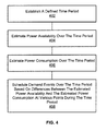
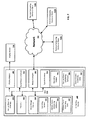
- FIG. 4 is a flowchart illustrating an embodiment of a method of the present invention.
- a defined time period such as time period 302 is established.
- the time period can be of any desired duration.
- the defined time period can be a time period of one hour, one day, one week, one month, one year, two years, five years, ten years, etc., or any period of time therebetween.
- estimating power availability over the time period comprises estimating internal power generation controlled by a utility and estimating acquired power availability that can be purchased from sources not controlled by the utility over the time period, wherein the internal power generation controlled by the utility includes fixed power generation and variable power generation.
- Estimating internal power generation controlled by the utility comprises estimating an amount and a cost for the fixed power generation and an amount and a cost for the variable power generation.
- a weather forecast for the defined time period can be used to estimate the amount and the cost of the variable power generation.
- Estimating acquired power availability that can be purchased from sources not controlled by the utility comprises estimating an amount and a cost for acquired power availability over the time period.
- Variable power generation can comprise one or more of wind generation, solar generation, hydroelectric generation, pumped-storage generation, steam-turbine generation, combustion-turbine generation, and the like.
- Fixed power generation can comprise one or more of nuclear generation, coal-fired generation, oil-fired generation, natural-gas fired generation, and the like.
- estimating power consumption over the time period comprises determining a load profile for each of a plurality of electrical power consumers over the time period and aggregating the plurality of load profiles.
- the load profiles are load profiles of residential, commercial and industrial consumers of electrical power that are aggregated over the time period.
- a demand event comprises a utility having authorization to discontinue electrical power service to all or part of an electrical load of one of the plurality of electrical power consumers for a predetermined duration and scheduling demand events over the time period based on differences between the estimated power availability and the estimated power consumption at various points during the time period comprises scheduling the demand events to decrease the estimated power consumption or increase the estimated power availability.
- scheduling demand events over the time period based on differences between the estimated power availability and the estimated power consumption at various points during the time period comprises scheduling the demand events to maximize revenue from sales of power by the utility over the time period and minimizing costs of fixed power generation, variable power generation and acquired power generation to the utility over the time period.
- scheduling demand events over the time period based on differences between the estimated power availability and the estimated power consumption at various points during the time period comprises scheduling the demand events to maximize revenue for the utility by scheduling a sale of estimated power availability that exceeds estimated power consumption and scheduling the demand events to minimize costs to the utility by minimizing purchases of acquired power generation when the cost of acquired power generation exceeds the cost of internal power generation and minimizes the use of variable power generation when the cost of variable power generation exceeds the cost of fixed power generation.
- the method described in FIG. 4 further comprises generating, by the computing device, one or more control signals for controlling the demand events over the time period based on differences between the estimated power availability and the estimated power consumption at various points during the time period.
- the computing device can generate one or more reports based on scheduling the demand events over the time period based on differences between the estimated power availability and the estimated power consumption at various points during the time period.
- the one or more reports comprise one or more of a report of a best fit use of the demand events using the internal power generation, a report on a best fit use of the demand events using the internal generation and the acquired power availability, and a report on opportunities for the utility to sell the internal power generation or the acquired power availability.
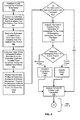
- FIG. 5 is a detailed flowchart illustrating another embodiment of a method of the present invention.
- a load forecast is established for a defined time period.
- the load forecast provides an estimation of power consumption over the time period.
- the load forecast is provided by a load forecasting and profiling system 204 that includes individual customer usage information as well as projected usage information over a specified time period, as described herein.
- estimated fixed power generation that is available over the time period is determined. Both, an amount and costs for the estimated fixed power generation is determined at step 504.
- Known events such as scheduled maintenance are taken into consideration at this step, as well as the probability of unknown events such as forced outages.
- an amount and costs for variable power generation that is available over the time period is determined.
- a weather forecast for the time period can be used to calculate a probability distribution of the variable power generation over the time period.
- gaps are determined where anticipated demand from the load forecasts exceeds total estimated available fixed and variable power generation.
- the demand profiles of customers enrolled in a demand management program are reviewed to determine a best-fit for scheduling demand events to cover the gaps.
- the cost of acquired power generation is analyzed in comparison to the cost of emergency generation in order to cover the gaps.
- periods of excess power generation are analyzed. These are periods (during the defined time period) when generation (whether fixed, variable, emergency or acquired) exceeds anticipated demand from the load forecasts.
- step 524 it is determined whether there are opportunities to sell any excess generation as determined in step 522. If so, then at step 526 any unallocated demand events for the determined time period are analyzed to see whether they can be used to enhance an ability to sell energy. This analysis can involve analyzing current and future energy sales markets to determine if the sale price exceeds the cost of generation. If so, then any remaining demand events can be utilized to maximize the amount of electrical energy that is available for sale. If, at step 524 it is determined that there are not any opportunities to sell excess energy, then the process goes to step 528. At step 528, one or more outputs are produced. In one aspect, the outputs comprise one or more reports.
- the one or more reports comprise one or more of a report of a best fit use of the demand events using the internal power generation, a report on a best fit use of the demand events using the internal generation and the acquired power availability, a report on opportunities for the utility to sell the internal power generation or the acquired power availability, or a report on the best fit of demand events using any combination of generated and/or acquired power.
- the outputs comprise one or more control signals for controlling the demand events over the time period based on differences between the estimated power availability and the estimated power consumption at various points during the time period.
- a unit such as computing device 108, meter 106, DRMS 202, load forecasting and profiling system 204, power generation and acquisition system 206, weather forecasting system 208, etc., can be software, hardware, or a combination of software and hardware.
- the units can comprise the demand event scheduling software 706 as illustrated in FIG. 7 and described below.
- the units can comprise a computing device 108 as referenced above and further described below.
- FIG. 7 is a block diagram illustrating an example operating environment for performing the disclosed methods.
- This example operating environment is only an example of an operating environment and is not intended to suggest any limitation as to the scope of use or functionality of operating environment architecture. Neither should the operating environment be interpreted as having any dependency or requirement relating to any one or combination of components illustrated in the example operating environment.
- the present methods and systems can be operational with numerous other general purpose or special purpose computing system environments or configurations.
- Examples of well-known computing systems, environments, and/or configurations that can be suitable for use with the systems and methods comprise, but are not limited to, personal computers, server computers, laptop devices, and multiprocessor systems. Additional examples comprise set top boxes, programmable consumer electronics, network PCs, minicomputers, mainframe computers, smart meters, smart-grid components, SCADA masters, distributed computing environments that comprise any of the above systems or devices, and the like.
- the processing of the disclosed methods and systems can be performed by software components.
- the disclosed systems and methods can be described in the general context of computer-executable instructions, such as program modules, being executed by one or more computers or other devices.
- program modules comprise computer code, routines, programs, objects, components, data structures, etc. that perform particular tasks or implement particular abstract data types.
- the disclosed methods can also be practiced in grid-based and distributed computing environments where tasks are performed by remote processing devices that are linked through a communications network.
- program modules can be located in both local and remote computer storage media including memory storage devices.
- the components of the computing device 108 can comprise, but are not limited to, one or more processors or processing units 703, a system memory 712, and a system bus 713 that couples various system components including the processor 703 to the system memory 712.
- the system can utilize parallel computing.
- the processor 703 is configured to establish a defined time period; estimate power availability over the time period; estimate power consumption over the time period; and schedule demand events stored in the memory 712 over the time period based on differences between the estimated power availability and the estimated power consumption at various points during the time period.
- the system bus 713 represents one or more of several possible types of bus structures, including a memory bus or memory controller, a peripheral bus, an accelerated graphics port, and a processor or local bus using any of a variety of bus architectures.
- bus architectures can comprise an Industry Standard Architecture (ISA) bus, a Micro Channel Architecture (MCA) bus, an Enhanced ISA (EISA) bus, a Video Electronics Standards Association (VESA) local bus, an Accelerated Graphics Port (AGP) bus, and a Peripheral Component Interconnects (PCI), a PCI-Express bus, a Personal Computer Memory Card Industry Association (PCMCIA), Universal Serial Bus (USB) and the like.
- ISA Industry Standard Architecture
- MCA Micro Channel Architecture
- EISA Enhanced ISA
- VESA Video Electronics Standards Association
- AGP Accelerated Graphics Port
- PCI Peripheral Component Interconnects
- PCI-Express PCI-Express
- PCMCIA Personal Computer Memory Card Industry Association
- USB Universal Serial Bus
- the bus 713, and all buses specified in this description can also be implemented over a wired or wireless network connection and each of the subsystems, including the processor 703, a mass storage device 704, an operating system 705, demand event scheduling software 706, demand event scheduling data 707, a network adapter 708, system memory 712, an Input/Output Interface 710, a display adapter 709, a display device 711, and a human machine interface 702, can be contained within one or more remote computing devices or clients 714a,b,c at physically separate locations, connected through buses of this form, in effect implementing a fully distributed system or distributed architecture.
- the computing device 108 typically comprises a variety of computer readable media.
- Example readable media can be any available media that is non-transitory and accessible by the computing device 108 and comprises, for example and not meant to be limiting, both volatile and non-volatile media, removable and non-removable media.
- the system memory 712 comprises computer readable media in the form of volatile memory, such as random access memory (RAM), and/or non-volatile memory, such as read only memory (ROM).
- RAM random access memory
- ROM read only memory
- the system memory 712 typically contains data such as phase identification data 707 and/or program modules such as operating system 705 and demand event scheduling software 706 that are immediately accessible to and/or are presently operated on by the processing unit 703.
- the system memory 712 contains computer executable codes sections for performing the steps of causing a signal to be transmitted to adjust one or more operational characteristics of an electrical device; receiving information about changes in at least one electrical parameter of one or more phases of a poly-phase electrical system that provides electrical energy to the electrical device; correlating the changes in the at least one electrical parameter of the one or more phases of the poly-phase electrical system that provides electrical energy to the electrical device with the adjustment of the one or more operational characteristics of the electrical device; and identifying the one or more phases of the poly-phase electrical system that provide electrical energy to the electrical device based upon the correlation of the changes in the at least one electrical parameter of the one or more phases of the poly-phase electrical system that provides electrical energy to the electrical device with the adjustment of the one or more operational characteristics of the electrical device.
- the computing device 108 can also comprise other non-transitory, removable/non-removable, volatile/non-volatile computer storage media.
- FIG. 7 illustrates a mass storage device 704 that can provide non-volatile storage of computer code, computer readable instructions, data structures, program modules, and other data for the computing device 108.
- a mass storage device 704 can be a hard disk, a removable magnetic disk, a removable optical disk, magnetic cassettes or other magnetic storage devices, flash memory cards, CD-ROM, digital versatile disks (DVD) or other optical storage, random access memories (RAM), read only memories (ROM), electrically erasable programmable read-only memory (EEPROM), and the like.
- any number of program modules can be stored on the mass storage device 704, including by way of example, an operating system 705 and demand event scheduling software 706.
- Each of the operating system 705 and demand event scheduling software 706 (or some combination thereof) can comprise elements of the programming and the demand event scheduling software 706.
- Demand event scheduling data 707 can also be stored on the mass storage device 704.
- Demand event scheduling data 707 can be stored in any of one or more databases known in the art. Examples of such databases comprise, DB2® (IBM Corporation, Armonk, NY), Microsoft® Access, Microsoft® SQL Server, (Microsoft Corporation, Bellevue, Washington), Oracle®, (Oracle Corporation, Redwood Shores, California), mySQL, PostgreSQL, and the like.
- the databases can be centralized or distributed across multiple systems.
- the user can enter commands and information into the computing device 108 via an input device (not shown).
- input devices comprise, but are not limited to, a keyboard, pointing device ( e . g ., a "mouse"), a microphone, a joystick, a scanner, tactile input devices such as gloves, and other body coverings, and the like
- a human machine interface 702 that is coupled to the system bus 713, but can be connected by other interface and bus structures, such as a parallel port, game port, an IEEE 1394 Port (also known as a Firewire port), a serial port, or a universal serial bus (USB).
- a display device 711 can also be connected to the system bus 713 via an interface, such as a display adapter 709. It is contemplated that the computing device 108 can have more than one display adapter 709 and the computing device 108 can have more than one display device 711.
- a display device can be a monitor, an LCD (Liquid Crystal Display), or a projector.
- other output peripheral devices can comprise components such as speakers (not shown) and a printer (not shown), which can be connected to the computer 108 via Input/Output Interface 710. Any step and/or result of the methods can be output in any form to an output device.
- Such output can be any form of visual representation, including, but not limited to, textual, graphical, animation, audio, tactile, and the like.
- the computing device 108 can operate in a networked environment using logical connections to one or more remote computing devices or clients 714a,b,c.
- a remote computing device 714 can be a personal computer, portable computer, a server, a router, a network computer, a smart meter, a vendor or manufacture's computing device, smart grid components, a SCADA master, a DRMS processor, a DMS processor, a peer device or other common network node, and so on and can be in support of one or more of DRMS 202, load forecasting and profiling system 204, power generation and acquisition system 206, weather forecasting system 208, etc.
- Logical connections between the computing device 108 and a remote computing device or client 714a,b,c can be made via a local area network (LAN) and a general wide area network (WAN). Such network connections can be through a network adapter 708.
- a network adapter 708 can be implemented in both wired and wireless environments. Such networking environments are conventional and commonplace in offices, enterprise-wide computer networks, intranets, and other networks 715 such as the Internet, an AMI network, or the like.
- application programs and other executable program components such as the operating system 705 are illustrated herein as discrete blocks, although it is recognized that such programs and components reside at various times in different storage components of the computing device 701, and are executed by the data processor(s) of the computer.
- An implementation of demand event scheduling software 706 can be stored on or transmitted across some form of computer readable media. Any of the disclosed methods can be performed by computer readable instructions embodied on computer readable media.
- Computer readable media can be any available media that can be accessed by a computer.
- Computer readable media can comprise “computer storage media” and “communications media.”
- “Computer storage media” comprise volatile and non-volatile, removable and non-removable media implemented in any methods or technology for storage of information such as computer readable instructions, data structures, program modules, or other data.
- Example computer storage media comprises, but is not limited to, RAM, ROM, EEPROM, flash memory or other memory technology, CD-ROM, digital versatile disks (DVD) or other optical storage, magnetic cassettes, magnetic tape, magnetic disk storage or other magnetic storage devices, or any other medium which can be used to store the desired information and which can be accessed by a computer.
- the methods and systems can employ Artificial Intelligence techniques such as machine learning and iterative learning.
- Artificial Intelligence techniques such as machine learning and iterative learning. Examples of such techniques include, but are not limited to, expert systems, case based reasoning, Bayesian networks, behavior based AI, neural networks, fuzzy systems, evolutionary computation (e.g. genetic algorithms), swarm intelligence (e.g. ant algorithms), and hybrid intelligent systems (e.g. Expert inference rules generated through a neural network or production rules from statistical learning).
- embodiments of the present invention may be configured as a system, method, or computer program product. Accordingly, embodiments of the present invention may be comprised of various means including entirely of hardware, entirely of software, or any combination of software and hardware. Furthermore, embodiments of the present invention may take the form of a computer program product on a computer-readable storage medium having computer-readable program instructions (e.g., computer software) embodied in the storage medium. Any suitable non-transitory computer-readable storage medium may be utilized including hard disks, CD-ROMs, optical storage devices, or magnetic storage devices.
- Embodiments of the present invention have been described above with reference to block diagrams and flowchart illustrations of methods, apparatuses (i.e., systems) and computer program products. It will be understood that each block of the block diagrams and flowchart illustrations, and combinations of blocks in the block diagrams and flowchart illustrations, respectively, can be implemented by various means including computer program instructions. These computer program instructions may be loaded onto a general purpose computer, special purpose computer, or other programmable data processing apparatus, such as the one or more processors 703 discussed above with reference to FIG. 7 , to produce a machine, such that the instructions which execute on the computer or other programmable data processing apparatus create a means for implementing the functions specified in the flowchart block or blocks.
- These computer program instructions may also be stored in a computer-readable memory that can direct a computer or other programmable data processing apparatus (e.g., one or more processors 703 of FIG. 7 ) to function in a particular manner, such that the instructions stored in the computer-readable memory produce an article of manufacture including computer-readable instructions for implementing the function specified in the flowchart block or blocks.
- the computer program instructions may also be loaded onto a computer or other programmable data processing apparatus to cause a series of operational steps to be performed on the computer or other programmable apparatus to produce a computer-implemented process such that the instructions that execute on the computer or other programmable apparatus provide steps for implementing the functions specified in the flowchart block or blocks.
- blocks of the block diagrams and flowchart illustrations support combinations of means for performing the specified functions, combinations of steps for performing the specified functions and program instruction means for performing the specified functions. It will also be understood that each block of the block diagrams and flowchart illustrations, and combinations of blocks in the block diagrams and flowchart illustrations, can be implemented by special purpose hardware-based computer systems that perform the specified functions or steps, or combinations of special purpose hardware and computer instructions.
Landscapes
- Engineering & Computer Science (AREA)
- Business, Economics & Management (AREA)
- Human Resources & Organizations (AREA)
- Strategic Management (AREA)
- Economics (AREA)
- Entrepreneurship & Innovation (AREA)
- Educational Administration (AREA)
- Game Theory and Decision Science (AREA)
- Development Economics (AREA)
- Marketing (AREA)
- Operations Research (AREA)
- Quality & Reliability (AREA)
- Tourism & Hospitality (AREA)
- Physics & Mathematics (AREA)
- General Business, Economics & Management (AREA)
- General Physics & Mathematics (AREA)
- Theoretical Computer Science (AREA)
- Management, Administration, Business Operations System, And Electronic Commerce (AREA)
- Supply And Distribution Of Alternating Current (AREA)
Applications Claiming Priority (1)
| Application Number | Priority Date | Filing Date | Title |
|---|---|---|---|
| US13/210,614 US8689020B2 (en) | 2011-08-16 | 2011-08-16 | Method, system and computer program product for scheduling demand events |
Publications (1)
| Publication Number | Publication Date |
|---|---|
| EP2560136A1 true EP2560136A1 (fr) | 2013-02-20 |
Family
ID=46801304
Family Applications (1)
| Application Number | Title | Priority Date | Filing Date |
|---|---|---|---|
| EP12180278A Ceased EP2560136A1 (fr) | 2011-08-16 | 2012-08-13 | Procédé, système et produit de programme informatique pour événements de demande de planification |
Country Status (6)
| Country | Link |
|---|---|
| US (1) | US8689020B2 (fr) |
| EP (1) | EP2560136A1 (fr) |
| JP (1) | JP6262934B2 (fr) |
| AU (1) | AU2012211435A1 (fr) |
| BR (1) | BR102012018606A2 (fr) |
| CA (1) | CA2784548C (fr) |
Cited By (5)
| Publication number | Priority date | Publication date | Assignee | Title |
|---|---|---|---|---|
| WO2014135219A1 (fr) * | 2013-03-08 | 2014-09-12 | Nec Europe Ltd. | Système et procédé pour distribuer du courant électrique |
| EP2863510A2 (fr) | 2013-10-21 | 2015-04-22 | Restore N.V. | Portefeuille géré, système de réponse côté demande |
| EP3076346A1 (fr) * | 2015-03-30 | 2016-10-05 | General Electric Company | Systèmes et procédés permettant un système de gestion de réponse à la demande amélioré (drms) |
| WO2018206993A1 (fr) * | 2017-05-11 | 2018-11-15 | Bull Sas | Procédé de gestion de fourniture d'électricité dans un groupe d'ordinateurs |
| EP3296947A4 (fr) * | 2015-05-15 | 2019-01-23 | Kabushiki Kaisha Toshiba | Système de centrale électrique et serveur de système de centrale électrique |
Families Citing this family (42)
| Publication number | Priority date | Publication date | Assignee | Title |
|---|---|---|---|---|
| US9721210B1 (en) * | 2013-11-26 | 2017-08-01 | Invent.ly LLC | Predictive power management in a wireless sensor network |
| US9137050B2 (en) | 2009-07-17 | 2015-09-15 | Honeywell International Inc. | Demand response system incorporating a graphical processing unit |
| US9124535B2 (en) | 2009-07-17 | 2015-09-01 | Honeywell International Inc. | System for using attributes to deploy demand response resources |
| US9818073B2 (en) | 2009-07-17 | 2017-11-14 | Honeywell International Inc. | Demand response management system |
| US9367825B2 (en) | 2009-10-23 | 2016-06-14 | Viridity Energy, Inc. | Facilitating revenue generation from wholesale electricity markets based on a self-tuning energy asset model |
| US9159042B2 (en) | 2009-10-23 | 2015-10-13 | Viridity Energy, Inc. | Facilitating revenue generation from data shifting by data centers |
| US9159108B2 (en) | 2009-10-23 | 2015-10-13 | Viridity Energy, Inc. | Facilitating revenue generation from wholesale electricity markets |
| US8892264B2 (en) | 2009-10-23 | 2014-11-18 | Viridity Energy, Inc. | Methods, apparatus and systems for managing energy assets |
| US8457802B1 (en) | 2009-10-23 | 2013-06-04 | Viridity Energy, Inc. | System and method for energy management |
| US9153001B2 (en) | 2011-01-28 | 2015-10-06 | Honeywell International Inc. | Approach for managing distribution of automated demand response events in a multi-site enterprise |
| US20150046221A1 (en) * | 2011-09-17 | 2015-02-12 | Autogrid Inc. | Load forecasting from individual customer to system level based on price |
| JP5776487B2 (ja) * | 2011-10-13 | 2015-09-09 | ソニー株式会社 | 電力制御装置およびプログラム |
| KR101500304B1 (ko) * | 2011-12-26 | 2015-03-11 | 주식회사 케이티 | 에너지 저장장치의 충방전 제어 방법 및 시스템 |
| US20130232151A1 (en) * | 2012-03-05 | 2013-09-05 | Green Charge Networks Llc | Aggregation of Load Profiles for Consumption Management Systems |
| WO2013172431A1 (fr) * | 2012-05-16 | 2013-11-21 | 京セラ株式会社 | Dispositif de gestion d'énergie, système de gestion d'énergie, et procédé de gestion d'énergie |
| US9831677B2 (en) | 2012-07-19 | 2017-11-28 | Solarcity Corporation | Software abstraction layer for energy generation and storage systems |
| US9270118B2 (en) * | 2012-07-19 | 2016-02-23 | Solarcity Corporation | Techniques for controlling energy generation and storage systems |
| US8849715B2 (en) * | 2012-10-24 | 2014-09-30 | Causam Energy, Inc. | System, method, and apparatus for settlement for participation in an electric power grid |
| US20140081704A1 (en) | 2012-09-15 | 2014-03-20 | Honeywell International Inc. | Decision support system based on energy markets |
| US9389850B2 (en) | 2012-11-29 | 2016-07-12 | Honeywell International Inc. | System and approach to manage versioning of field devices in a multi-site enterprise |
| JP2014143835A (ja) * | 2013-01-24 | 2014-08-07 | Toshiba Corp | 電力系統の制御システム |
| US9810442B2 (en) | 2013-03-15 | 2017-11-07 | Google Inc. | Controlling an HVAC system in association with a demand-response event with an intelligent network-connected thermostat |
| US9595070B2 (en) | 2013-03-15 | 2017-03-14 | Google Inc. | Systems, apparatus and methods for managing demand-response programs and events |
| US9807099B2 (en) | 2013-03-15 | 2017-10-31 | Google Inc. | Utility portals for managing demand-response events |
| US9098876B2 (en) * | 2013-05-06 | 2015-08-04 | Viridity Energy, Inc. | Facilitating revenue generation from wholesale electricity markets based on a self-tuning energy asset model |
| US9171276B2 (en) * | 2013-05-06 | 2015-10-27 | Viridity Energy, Inc. | Facilitating revenue generation from wholesale electricity markets using an engineering-based model |
| US10346931B2 (en) | 2013-07-11 | 2019-07-09 | Honeywell International Inc. | Arrangement for communicating demand response resource incentives |
| US9989937B2 (en) | 2013-07-11 | 2018-06-05 | Honeywell International Inc. | Predicting responses of resources to demand response signals and having comfortable demand responses |
| US9691076B2 (en) | 2013-07-11 | 2017-06-27 | Honeywell International Inc. | Demand response system having a participation predictor |
| US20150186904A1 (en) * | 2013-12-27 | 2015-07-02 | International Business Machines Corporation | System And Method For Managing And Forecasting Power From Renewable Energy Sources |
| US9665078B2 (en) | 2014-03-25 | 2017-05-30 | Honeywell International Inc. | System for propagating messages for purposes of demand response |
| SG10201406883UA (en) * | 2014-10-23 | 2016-05-30 | Sun Electric Pte Ltd | "Power Grid System And Method Of Consolidating Power Injection And Consumption In A Power Grid System" |
| WO2016158028A1 (fr) * | 2015-03-30 | 2016-10-06 | オムロン株式会社 | Dispositif de gestion, système de gestion, procédé de commande for dispositif de gestion, et programme de commande |
| US10855484B2 (en) * | 2015-07-03 | 2020-12-01 | University Of South Africa | Electronic controller for household energy control based on timing and tariff data |
| AU2016324172A1 (en) | 2015-09-17 | 2018-04-19 | Washlava, Inc. | System for commercial laundry services and facilities |
| US10191506B2 (en) * | 2016-09-29 | 2019-01-29 | Enel X North America, Inc. | Demand response dispatch prediction system including automated validation, estimation, and editing rules configuration engine |
| US10541556B2 (en) | 2017-04-27 | 2020-01-21 | Honeywell International Inc. | System and approach to integrate and manage diverse demand response specifications for multi-site enterprises |
| US10999652B2 (en) | 2017-05-24 | 2021-05-04 | Engie Storage Services Na Llc | Energy-based curtailment systems and methods |
| US10658841B2 (en) | 2017-07-14 | 2020-05-19 | Engie Storage Services Na Llc | Clustered power generator architecture |
| US20190123580A1 (en) * | 2017-10-23 | 2019-04-25 | Sigora International Inc. | Management of a power-distribution system |
| KR102665459B1 (ko) * | 2020-09-14 | 2024-05-13 | 한국전자통신연구원 | 주택 단지용 태양광 발전을 위한 용량 설계 장치 및 용량 설계 방법 |
| JP2023178053A (ja) * | 2022-06-03 | 2023-12-14 | パナソニックIpマネジメント株式会社 | 制御システム、制御方法、プログラム及び連系システム |
Citations (1)
| Publication number | Priority date | Publication date | Assignee | Title |
|---|---|---|---|---|
| EP2339517A1 (fr) * | 2009-12-23 | 2011-06-29 | General Electric Company | Procédé et système de gestion de réponse de demande dans un réseau |
Family Cites Families (22)
| Publication number | Priority date | Publication date | Assignee | Title |
|---|---|---|---|---|
| US3602703A (en) | 1969-10-20 | 1971-08-31 | Ibm | Power demand predicting control system |
| US4464724A (en) | 1981-06-17 | 1984-08-07 | Cyborex Laboratories, Inc. | System and method for optimizing power shed/restore operations |
| US4916328A (en) | 1988-12-08 | 1990-04-10 | Honeywell Inc. | Add/shed load control using anticipatory processes |
| US5414640A (en) | 1991-07-05 | 1995-05-09 | Johnson Service Company | Method and apparatus for adaptive demand limiting electric consumption through load shedding |
| JP2001318970A (ja) * | 2000-05-12 | 2001-11-16 | Nippon Steel Corp | 電力の需給制御方法、電力の需給制御装置、電力の需給制御システム及び記憶媒体 |
| US6519509B1 (en) | 2000-06-22 | 2003-02-11 | Stonewater Software, Inc. | System and method for monitoring and controlling energy distribution |
| JP3779151B2 (ja) * | 2000-12-08 | 2006-05-24 | 株式会社日立製作所 | インセンティブ電力負荷制御方法およびシステム |
| US7136725B1 (en) | 2001-06-21 | 2006-11-14 | Paciorek Ronald R | Load shed notification method, product, and apparatus |
| JP2005284420A (ja) * | 2004-03-26 | 2005-10-13 | Tokyo Electric Power Co Inc:The | 電力資源取引システムおよび電力資源取引管理サーバ |
| JP2006352933A (ja) * | 2005-06-13 | 2006-12-28 | Hitachi Ltd | 電力供給制御方法および電力供給制御システム |
| GB0809235D0 (en) * | 2008-05-21 | 2008-06-25 | Poweroasis Ltd | Supervisory system controller for use with a renewable energy powered radio telecommunications site |
| US8260468B2 (en) | 2008-06-25 | 2012-09-04 | Versify Solutions, Inc. | Aggregator, monitor, and manager of distributed demand response |
| US8548638B2 (en) * | 2008-09-15 | 2013-10-01 | General Electric Company | Energy management system and method |
| US8626344B2 (en) | 2009-08-21 | 2014-01-07 | Allure Energy, Inc. | Energy management system and method |
| JP5685715B2 (ja) * | 2009-09-28 | 2015-03-18 | パナソニックIpマネジメント株式会社 | 系統連系形給電システム |
| US8457802B1 (en) | 2009-10-23 | 2013-06-04 | Viridity Energy, Inc. | System and method for energy management |
| US8401709B2 (en) | 2009-11-03 | 2013-03-19 | Spirae, Inc. | Dynamic distributed power grid control system |
| JP2011114945A (ja) * | 2009-11-26 | 2011-06-09 | Fuji Electric Systems Co Ltd | 供給電力計画作成装置、そのプログラム |
| US8386086B2 (en) | 2010-04-26 | 2013-02-26 | Accenture Global Services Limited | Methods and systems for analyzing energy usage |
| US8521337B1 (en) | 2010-07-20 | 2013-08-27 | Calm Energy Inc. | Systems and methods for operating electrical supply |
| US8417391B1 (en) | 2011-12-15 | 2013-04-09 | Restore Nv | Automated demand response energy management system |
| US8965594B2 (en) | 2012-01-19 | 2015-02-24 | General Compression, Inc. | System and method for conserving energy resources through storage and delivery of renewable energy |
-
2011
- 2011-08-16 US US13/210,614 patent/US8689020B2/en active Active
-
2012
- 2012-07-26 BR BR102012018606-3A patent/BR102012018606A2/pt not_active IP Right Cessation
- 2012-08-02 CA CA2784548A patent/CA2784548C/fr active Active
- 2012-08-08 AU AU2012211435A patent/AU2012211435A1/en not_active Abandoned
- 2012-08-10 JP JP2012177624A patent/JP6262934B2/ja active Active
- 2012-08-13 EP EP12180278A patent/EP2560136A1/fr not_active Ceased
Patent Citations (1)
| Publication number | Priority date | Publication date | Assignee | Title |
|---|---|---|---|---|
| EP2339517A1 (fr) * | 2009-12-23 | 2011-06-29 | General Electric Company | Procédé et système de gestion de réponse de demande dans un réseau |
Non-Patent Citations (2)
| Title |
|---|
| ED KOCH ET AL: "Architecture Concepts and Technical Issues for an Open, Interoperable Automated Demand Response Infrastructure", GRID INTEROP FORUM, November 2007 (2007-11-01), XP055043807, Retrieved from the Internet <URL:http://drrc.lbl.gov/system/files/63664.pdf> [retrieved on 20121112] * |
| PETER PALENSKY ET AL: "Demand Side Management: Demand Response, Intelligent Energy Systems, and Smart Loads", IEEE TRANSACTIONS ON INDUSTRIAL INFORMATICS, IEEE SERVICE CENTER, NEW YORK, NY, US, vol. 7, no. 3, 10 August 2011 (2011-08-10), pages 381 - 388, XP011371288, ISSN: 1551-3203, DOI: 10.1109/TII.2011.2158841 * |
Cited By (10)
| Publication number | Priority date | Publication date | Assignee | Title |
|---|---|---|---|---|
| WO2014135219A1 (fr) * | 2013-03-08 | 2014-09-12 | Nec Europe Ltd. | Système et procédé pour distribuer du courant électrique |
| EP2863510A2 (fr) | 2013-10-21 | 2015-04-22 | Restore N.V. | Portefeuille géré, système de réponse côté demande |
| WO2015059544A2 (fr) | 2013-10-21 | 2015-04-30 | Restore Nv | Système de réponse côté demande à gestion de portefeuille |
| EP2961022A1 (fr) | 2013-10-21 | 2015-12-30 | Restore N.V. | Portefeuille gere, systeme de reponse cote demande |
| US9471080B2 (en) | 2013-10-21 | 2016-10-18 | Restore Nv | Portfolio managed, demand-side response system |
| EP3076346A1 (fr) * | 2015-03-30 | 2016-10-05 | General Electric Company | Systèmes et procédés permettant un système de gestion de réponse à la demande amélioré (drms) |
| JP2016192891A (ja) * | 2015-03-30 | 2016-11-10 | ゼネラル・エレクトリック・カンパニイ | 改善されたデマンドレスポンス管理システム(drms)のためのシステムおよび方法 |
| EP3296947A4 (fr) * | 2015-05-15 | 2019-01-23 | Kabushiki Kaisha Toshiba | Système de centrale électrique et serveur de système de centrale électrique |
| WO2018206993A1 (fr) * | 2017-05-11 | 2018-11-15 | Bull Sas | Procédé de gestion de fourniture d'électricité dans un groupe d'ordinateurs |
| US11381082B2 (en) | 2017-05-11 | 2022-07-05 | Bull Sas | Method of managing electricity providing in a computers cluster |
Also Published As
| Publication number | Publication date |
|---|---|
| CA2784548C (fr) | 2019-09-24 |
| CA2784548A1 (fr) | 2013-02-16 |
| JP2013042652A (ja) | 2013-02-28 |
| NZ601720A (en) | 2014-02-28 |
| US8689020B2 (en) | 2014-04-01 |
| BR102012018606A2 (pt) | 2013-11-05 |
| AU2012211435A1 (en) | 2013-03-07 |
| JP6262934B2 (ja) | 2018-01-17 |
| US20130047010A1 (en) | 2013-02-21 |
Similar Documents
| Publication | Publication Date | Title |
|---|---|---|
| US8689020B2 (en) | Method, system and computer program product for scheduling demand events | |
| US11860661B2 (en) | Method and apparatus to assess and control energy efficiency of pump installed in facility of building systems | |
| AU2022202616B2 (en) | Method and apparatus for facilitating the operation of an on-site energy storage system to co-optimize battery dispatch | |
| Hao et al. | Potentials and economics of residential thermal loads providing regulation reserve | |
| Yu et al. | A statistical demand-price model with its application in optimal real-time price | |
| US9960637B2 (en) | Renewable energy integrated storage and generation systems, apparatus, and methods with cloud distributed energy management services | |
| Oprea et al. | Flattening the electricity consumption peak and reducing the electricity payment for residential consumers in the context of smart grid by means of shifting optimization algorithm | |
| US20120136496A1 (en) | System and method for estimating demand response in electric power systems | |
| US11429075B2 (en) | System, apparatus and method for energy management, for usage by consumers of energy from electric utility service providers, and monitoring and management of same | |
| US20110258018A1 (en) | System and method for scheduling demand response events in a network | |
| Goebel | On the business value of ICT-controlled plug-in electric vehicle charging in California | |
| EP2605199A1 (fr) | Modélisation de désutilité d'énergie pour réponse agile à une demande | |
| JP2020501491A (ja) | 動的エネルギーストレージシステム制御のためのシステムおよび方法 | |
| Yang et al. | Quantifying the benefits to consumers for demand response with a statistical elasticity model | |
| US20140049545A1 (en) | Method and system for optimizing utility cost | |
| AU2014252667A1 (en) | System and method for performing demand response optimizations | |
| Malik et al. | Integration of automated Demand Response and Energy Efficiency to enable a smart grid infrastructure | |
| Mathieu et al. | Characterizing the response of commercial and industrial facilities to dynamic pricing signals from the utility | |
| NZ601720B (en) | Method, system and computer program product for scheduling demand events | |
| Beaudin | On optimal scheduling of residential energy management systems | |
| Priolkar et al. | Impact of demand response implementation in India with focus on analysis of consumer baseline load | |
| George et al. | Smart home energy management systems in India: a socio-economic commitment towards a green future | |
| Piette et al. | Using Building Loads Dynamically with Advanced Technologies to Enable Low Carbon Energy Systems | |
| Scarcello et al. | Models and enabling IoT technologies for cooperative energy brokerage in smart-grid | |
| Arlt et al. | Curtailment Contract Design for HVAC Systems and Benefits for Management of Uncertain Generation |
Legal Events
| Date | Code | Title | Description |
|---|---|---|---|
| PUAI | Public reference made under article 153(3) epc to a published international application that has entered the european phase |
Free format text: ORIGINAL CODE: 0009012 |
|
| AK | Designated contracting states |
Kind code of ref document: A1 Designated state(s): AL AT BE BG CH CY CZ DE DK EE ES FI FR GB GR HR HU IE IS IT LI LT LU LV MC MK MT NL NO PL PT RO RS SE SI SK SM TR |
|
| AX | Request for extension of the european patent |
Extension state: BA ME |
|
| 17P | Request for examination filed |
Effective date: 20130820 |
|
| RBV | Designated contracting states (corrected) |
Designated state(s): AL AT BE BG CH CY CZ DE DK EE ES FI FR GB GR HR HU IE IS IT LI LT LU LV MC MK MT NL NO PL PT RO RS SE SI SK SM TR |
|
| 17Q | First examination report despatched |
Effective date: 20140122 |
|
| STAA | Information on the status of an ep patent application or granted ep patent |
Free format text: STATUS: THE APPLICATION HAS BEEN REFUSED |
|
| 18R | Application refused |
Effective date: 20180531 |