EP2559989A1 - Exhaust sensor alignment structure - Google Patents
Exhaust sensor alignment structure Download PDFInfo
- Publication number
- EP2559989A1 EP2559989A1 EP11768815A EP11768815A EP2559989A1 EP 2559989 A1 EP2559989 A1 EP 2559989A1 EP 11768815 A EP11768815 A EP 11768815A EP 11768815 A EP11768815 A EP 11768815A EP 2559989 A1 EP2559989 A1 EP 2559989A1
- Authority
- EP
- European Patent Office
- Prior art keywords
- exhaust
- pipe
- exhaust gas
- exhaust sensor
- engine
- Prior art date
- Legal status (The legal status is an assumption and is not a legal conclusion. Google has not performed a legal analysis and makes no representation as to the accuracy of the status listed.)
- Granted
Links
Images

Classifications
-
- F—MECHANICAL ENGINEERING; LIGHTING; HEATING; WEAPONS; BLASTING
- F01—MACHINES OR ENGINES IN GENERAL; ENGINE PLANTS IN GENERAL; STEAM ENGINES
- F01N—GAS-FLOW SILENCERS OR EXHAUST APPARATUS FOR MACHINES OR ENGINES IN GENERAL; GAS-FLOW SILENCERS OR EXHAUST APPARATUS FOR INTERNAL-COMBUSTION ENGINES
- F01N13/00—Exhaust or silencing apparatus characterised by constructional features
-
- F—MECHANICAL ENGINEERING; LIGHTING; HEATING; WEAPONS; BLASTING
- F01—MACHINES OR ENGINES IN GENERAL; ENGINE PLANTS IN GENERAL; STEAM ENGINES
- F01N—GAS-FLOW SILENCERS OR EXHAUST APPARATUS FOR MACHINES OR ENGINES IN GENERAL; GAS-FLOW SILENCERS OR EXHAUST APPARATUS FOR INTERNAL-COMBUSTION ENGINES
- F01N13/00—Exhaust or silencing apparatus characterised by constructional features
- F01N13/008—Mounting or arrangement of exhaust sensors in or on exhaust apparatus
-
- G—PHYSICS
- G01—MEASURING; TESTING
- G01N—INVESTIGATING OR ANALYSING MATERIALS BY DETERMINING THEIR CHEMICAL OR PHYSICAL PROPERTIES
- G01N1/00—Sampling; Preparing specimens for investigation
- G01N1/02—Devices for withdrawing samples
- G01N1/22—Devices for withdrawing samples in the gaseous state
- G01N1/2247—Sampling from a flowing stream of gas
- G01N1/2252—Sampling from a flowing stream of gas in a vehicle exhaust
-
- F—MECHANICAL ENGINEERING; LIGHTING; HEATING; WEAPONS; BLASTING
- F01—MACHINES OR ENGINES IN GENERAL; ENGINE PLANTS IN GENERAL; STEAM ENGINES
- F01N—GAS-FLOW SILENCERS OR EXHAUST APPARATUS FOR MACHINES OR ENGINES IN GENERAL; GAS-FLOW SILENCERS OR EXHAUST APPARATUS FOR INTERNAL-COMBUSTION ENGINES
- F01N2560/00—Exhaust systems with means for detecting or measuring exhaust gas components or characteristics
- F01N2560/05—Exhaust systems with means for detecting or measuring exhaust gas components or characteristics the means being a particulate sensor
-
- G—PHYSICS
- G01—MEASURING; TESTING
- G01N—INVESTIGATING OR ANALYSING MATERIALS BY DETERMINING THEIR CHEMICAL OR PHYSICAL PROPERTIES
- G01N15/00—Investigating characteristics of particles; Investigating permeability, pore-volume or surface-area of porous materials
- G01N15/06—Investigating concentration of particle suspensions
- G01N15/0656—Investigating concentration of particle suspensions using electric, e.g. electrostatic methods or magnetic methods
-
- Y—GENERAL TAGGING OF NEW TECHNOLOGICAL DEVELOPMENTS; GENERAL TAGGING OF CROSS-SECTIONAL TECHNOLOGIES SPANNING OVER SEVERAL SECTIONS OF THE IPC; TECHNICAL SUBJECTS COVERED BY FORMER USPC CROSS-REFERENCE ART COLLECTIONS [XRACs] AND DIGESTS
- Y10—TECHNICAL SUBJECTS COVERED BY FORMER USPC
- Y10T—TECHNICAL SUBJECTS COVERED BY FORMER US CLASSIFICATION
- Y10T137/00—Fluid handling
- Y10T137/794—With means for separating solid material from the fluid
-
- Y—GENERAL TAGGING OF NEW TECHNOLOGICAL DEVELOPMENTS; GENERAL TAGGING OF CROSS-SECTIONAL TECHNOLOGIES SPANNING OVER SEVERAL SECTIONS OF THE IPC; TECHNICAL SUBJECTS COVERED BY FORMER USPC CROSS-REFERENCE ART COLLECTIONS [XRACs] AND DIGESTS
- Y10—TECHNICAL SUBJECTS COVERED BY FORMER USPC
- Y10T—TECHNICAL SUBJECTS COVERED BY FORMER US CLASSIFICATION
- Y10T137/00—Fluid handling
- Y10T137/8593—Systems
- Y10T137/85978—With pump
-
- Y—GENERAL TAGGING OF NEW TECHNOLOGICAL DEVELOPMENTS; GENERAL TAGGING OF CROSS-SECTIONAL TECHNOLOGIES SPANNING OVER SEVERAL SECTIONS OF THE IPC; TECHNICAL SUBJECTS COVERED BY FORMER USPC CROSS-REFERENCE ART COLLECTIONS [XRACs] AND DIGESTS
- Y10—TECHNICAL SUBJECTS COVERED BY FORMER USPC
- Y10T—TECHNICAL SUBJECTS COVERED BY FORMER US CLASSIFICATION
- Y10T137/00—Fluid handling
- Y10T137/8593—Systems
- Y10T137/85978—With pump
- Y10T137/85986—Pumped fluid control
Definitions
- This invention relates to a structure for arrangement of an exhaust sensor in an engine, the exhaust sensor being for measuring exhaust gas components and requiring air for the measurement of the exhaust gas components.
- Some exhaust sensors exposed to exhaust gas require air for avoiding contamination with exhaust gas components, or for using the air as a reference in concentration measurement of the exhaust gas components. Such air is supplied in different ways depending on characteristics of the exhaust sensors.
- the PM sensor When the exhaust sensor is used as an on-vehicle PM sensor, the PM sensor requires air for measurement of exhaust gas components, and is typically designed on the assumption that the air is supplied to the PM sensor by positive pressure generated by an air compressor or turbo compressor.
- Patent Document 1 W02009/109688
- engines with low engine displacement such as those for passenger cars or small-sized commercial vehicles usually are not provided with an air compressor for generating positive pressure.
- the exhaust sensor when using positive pressure generated by a turbo compressor, the exhaust sensor may possibly be contaminated with oil leaked from a sealing portion of the turbo compressor or oil contained in blowby gas.
- An object of the invention is therefore to enable an exhaust sensor to be supplied with air required for measurement of exhaust gas components without the need of using a device for generating positive pressure.
- the invention provides an exhaust sensor arrangement structure which is a structure for arrangement, in an engine, of an exhaust sensor that measures exhaust gas components and requires air for the measurement of the exhaust gas components.
- an exhaust pipe of the engine communicates with the exhaust sensor through an introduction pipe
- the exhaust sensor communicates with an intake pipe of the engine through a discharge pipe
- an atmosphere pipe open to the atmosphere is connected to the exhaust sensor, so that exhaust gas is sucked into the exhaust sensor through the introduction pipe while the air is sucked into the exhaust sensor through the atmosphere pipe due to intake negative pressure generated during an intake stroke of the engine.
- a turbo compressor may be provided in the intake pipe, and the discharge pipe may be connected to the intake pipe on an upstream side of the turbo compressor in terms of flow of intake air.
- a turbine for driving the turbo compressor may be provided in the exhaust pipe, and the introduction pipe may be connected to the exhaust pipe on a downstream side of the turbine in terms of flow of the exhaust gas.
- An exhaust gas post-treatment apparatus may be provided in the exhaust pipe on the downstream side of the turbine in terms of flow of the exhaust gas, and the introduction pipe may be connected to the exhaust pipe on a downstream side of the exhaust gas post-treatment apparatus in terms of flow of the exhaust gas.
- An exhaust gas post-treatment apparatus may be provided in the exhaust pipe on the downstream side of the turbine in terms of flow of the exhaust gas, and the introduction pipe may be connected to the exhaust pipe on an upstream side of the exhaust gas post-treatment apparatus in terms of flow of the exhaust gas.
- a metering valve may be provided in the discharge pipe.
- a filter may be provided in the atmosphere pipe.
- This invention provides an excellent effect that the exhaust sensor can be supplied with air required for measurement of exhaust gas components without using any device for generating positive pressure.
- Fig. 1 is a schematic diagram of an engine to which an exhaust sensor arrangement structure according to an embodiment of the invention is applied;
- the reference numeral 1 denotes an engine (diesel engine in this embodiment)
- 2 denotes an intake pipe connected to an intake port 1a of the engine 1
- 3 denotes an air cleaner provided in the intake pipe 2
- 4 denotes turbo compressor (turbo charger compressor) for increasing the pressure of intake air supplied to the engine 1, provided in the intake pipe 2 on the downstream side of the air cleaner 3 in terms of flow of the intake air
- 5 denotes an exhaust pipe (tail pipe) connected to an exhaust port 1b of the engine
- 6 denotes a turbine provided in the exhaust pipe 5 for driving the turbo compressor 4
- 7 denotes an exhaust gas post-treatment apparatus provided in the exhaust pipe 5 on the downstream side of the turbine 6 in terms of flow of exhaust gas.
- the exhaust gas post-treatment apparatus 7 has, for example, a diesel particulate filter (DPF) for collecting particulate matters (PM) contained in the exhaust gas.
- DPF diesel particulate filter
- the exhaust sensor 10 is a sensor which can be mounted on a vehicle and is designed on the assumption that the vehicle has an on-board diagnostics (OBD) function.
- the exhaust sensor 10 is a PM sensor which electrically charges air supplied thereto and detects an emission of particulate matters (PM) based on a variation in electrical charge.
- the exhaust sensor 10 has a nozzle 11 for ejecting air from the front end thereof, a cylindrical or sheath-shaped inner case 13 covering the nozzle 11 and having a throttle portion 12 for throttling the air ejected from the front end of the nozzle 11, a cylindrical or sheath-shaped outer case 14 covering the inner case 13, and an electrode (not shown) for electrically charging the air.
- the nozzle 11, the inner case 13 and the outer case 14 are arranged concentrically with each other.
- the inner case 13 and the outer case 14 are respectively provided with gas inlets 13a, 14a for introducing the exhaust gas into the inside of the exhaust sensor 10 (into the inside of the inner case 13 according to this embodiment), and gas outlets 13b, 14b for discharging the exhaust gas from the exhaust sensor 10 (from the inner case 13 according to this embodiment).
- the gas inlets 13a, 14a and the gas outlets 13b, 14b are arranged at intervals in a longitudinal direction of the inner case 13 and the outer case 14.
- the exhaust pipe 5 of the engine 1 communicates with the exhaust sensor 10 through the introduction pipe 15, and the exhaust sensor 10 communicates with the intake pipe 2 of the engine 1 through the discharge pipe 16.
- An atmosphere pipe 17 open to the atmosphere is connected to the exhaust sensor 10.
- the discharge pipe 16 is provided with a metering valve 18 for adjusting the flow rate of the exhaust gas and the air supplied to the exhaust sensor 10.
- the atmosphere pipe 17 is provided with a filter 19 for filtering the air supplied to the exhaust sensor 10.
- the atmosphere pipe 17 is connected to the base end of the nozzle 11.
- one end of the introduction pipe 15 is connected to the exhaust pipe 5 on the downstream side of the exhaust gas post-treatment apparatus 7 in terms of flow of the exhaust gas, while the other end of the introduction pipe 15 is connected to the inner case 13 and outer case 14 (the gas inlets 13a, 14a) of the exhaust sensor 10.
- One end of the discharge pipe 16 is connected to the inner case 13 and outer case 14 (the gas outlets 13b, 14b) of the exhaust sensor 10, and the other end of the discharge pipe 16 is connected to the intake pipe 2 on the upstream side of the turbo compressor 4 in terms of flow of the exhaust gas (in the example shown in Fig. 1 , connected to the intake pipe 2 between the turbo compressor 4 and the air cleaner 3).
- the exhaust sensor 10 is arranged between an engine air-intake system and an engine exhaust system. Specifically, the exhaust sensor 10 communicates with the intake pipe 2 of the engine 1 through the discharge pipe 16, and communicates with the exhaust pipe 5 of the engine 1 through the introduction pipe 15. Accordingly, the air (atmosphere) is sucked toward the intake port 1a of the engine 1 from the air cleaner 3 and the filter 19 due to negative pressure generated within the intake pipe 2 during an intake stroke of the engine 1. The air sucked in from the filter 19 is supplied to the inside of the exhaust sensor 10 through the atmosphere pipe 17.
- the engine exhaust system (the exhaust pipe 5 of the engine 1) communicates with the exhaust sensor 10 through the introduction pipe 15. Therefore, the exhaust gas within the exhaust pipe 5 of the engine 1 is also sucked toward the intake port 1a of the engine 1 due to negative pressure generated in the inside of the intake pipe 2 during an intake stroke of the engine 1.
- the sucked-in exhaust gas is supplied to the inside of the exhaust sensor 10 through the introduction pipe 15.
- the exhaust pipe 5 of the engine 1 communicates with the exhaust sensor 10 through the introduction pipe 15
- the exhaust sensor 10 communicates with the intake pipe 2 of the engine 1 through the discharge pipe 16
- the atmosphere pipe 17 open to the atmosphere is connected to the exhaust sensor 10, so that the exhaust gas is sucked into the exhaust sensor 10 through the introduction pipe 15 and the air is sucked into the exhaust sensor 10 through the atmosphere pipe 17 due to intake negative pressure generated during an intake stroke of the engine 1.
- the turbo compressor 4 is provided in the intake pipe 2 and the discharge pipe 16 is connected to the intake pipe 2 on the upstream side of the turbo compressor 4 in terms of flow of the intake air, which makes it easy to generate a pressure difference between the introduction pipe 15 and the discharge pipe 16.
- the exhaust gas and the air can be efficiently supplied to the inside of the exhaust sensor 10.
- the metering valve 18 is provided in the discharge pipe 16, so that the pressure difference between the introduction pipe 15 and the discharge pipe 16 can be varied by this metering valve 18. This makes it possible to appropriately adjust the flow rate of the exhaust gas and the air supplied into the exhaust sensor 10.
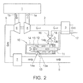
- the filter 19 for filtering the air supplied to the exhaust sensor 10 is provided independently from the air cleaner 3, the air cleaner 3 can be shared by the intake pipe 2 and the atmosphere pipe 17, as shown in Fig. 2 , when an adequate negative pressure is generated by air intake resistance or the like.
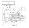
- the point where the introduction pipe 15 communicates can be shifted to a point of the exhaust pipe 5 on the upstream side of the exhaust gas post-treatment apparatus 7 in terms of flow of the exhaust gas.
- the exhaust sensor 10 is not limited to a PM sensor, but may be any other sensor for measuring exhaust gas components other than PM as long as it requires air.
Landscapes
- Engineering & Computer Science (AREA)
- Chemical & Material Sciences (AREA)
- Analytical Chemistry (AREA)
- Combustion & Propulsion (AREA)
- Mechanical Engineering (AREA)
- General Engineering & Computer Science (AREA)
- Health & Medical Sciences (AREA)
- Life Sciences & Earth Sciences (AREA)
- Physics & Mathematics (AREA)
- Molecular Biology (AREA)
- Biomedical Technology (AREA)
- Biochemistry (AREA)
- General Health & Medical Sciences (AREA)
- General Physics & Mathematics (AREA)
- Immunology (AREA)
- Pathology (AREA)
- Exhaust Gas After Treatment (AREA)
- Exhaust Silencers (AREA)
- Testing Of Engines (AREA)
- Processes For Solid Components From Exhaust (AREA)
Abstract
Description
- This invention relates to a structure for arrangement of an exhaust sensor in an engine, the exhaust sensor being for measuring exhaust gas components and requiring air for the measurement of the exhaust gas components.
- Some exhaust sensors exposed to exhaust gas require air for avoiding contamination with exhaust gas components, or for using the air as a reference in concentration measurement of the exhaust gas components. Such air is supplied in different ways depending on characteristics of the exhaust sensors.
- When the exhaust sensor is used as an on-vehicle PM sensor, the PM sensor requires air for measurement of exhaust gas components, and is typically designed on the assumption that the air is supplied to the PM sensor by positive pressure generated by an air compressor or turbo compressor.
- Patent Document 1:
W02009/109688 - However, engines with low engine displacement such as those for passenger cars or small-sized commercial vehicles usually are not provided with an air compressor for generating positive pressure.
- Moreover, when using positive pressure generated by a turbo compressor, the exhaust sensor may possibly be contaminated with oil leaked from a sealing portion of the turbo compressor or oil contained in blowby gas.
- An object of the invention is therefore to enable an exhaust sensor to be supplied with air required for measurement of exhaust gas components without the need of using a device for generating positive pressure.
- In order to achieve the aforementioned object, the invention provides an exhaust sensor arrangement structure which is a structure for arrangement, in an engine, of an exhaust sensor that measures exhaust gas components and requires air for the measurement of the exhaust gas components. In the exhaust sensor arrangement structure, an exhaust pipe of the engine communicates with the exhaust sensor through an introduction pipe, the exhaust sensor communicates with an intake pipe of the engine through a discharge pipe, and an atmosphere pipe open to the atmosphere is connected to the exhaust sensor, so that exhaust gas is sucked into the exhaust sensor through the introduction pipe while the air is sucked into the exhaust sensor through the atmosphere pipe due to intake negative pressure generated during an intake stroke of the engine.
- A turbo compressor may be provided in the intake pipe, and the discharge pipe may be connected to the intake pipe on an upstream side of the turbo compressor in terms of flow of intake air.
- A turbine for driving the turbo compressor may be provided in the exhaust pipe, and the introduction pipe may be connected to the exhaust pipe on a downstream side of the turbine in terms of flow of the exhaust gas.
- An exhaust gas post-treatment apparatus may be provided in the exhaust pipe on the downstream side of the turbine in terms of flow of the exhaust gas, and the introduction pipe may be connected to the exhaust pipe on a downstream side of the exhaust gas post-treatment apparatus in terms of flow of the exhaust gas.
- An exhaust gas post-treatment apparatus may be provided in the exhaust pipe on the downstream side of the turbine in terms of flow of the exhaust gas, and the introduction pipe may be connected to the exhaust pipe on an upstream side of the exhaust gas post-treatment apparatus in terms of flow of the exhaust gas.
- A metering valve may be provided in the discharge pipe.
- A filter may be provided in the atmosphere pipe.
- This invention provides an excellent effect that the exhaust sensor can be supplied with air required for measurement of exhaust gas components without using any device for generating positive pressure.
-
Fig. 1 is a schematic diagram of an engine to which an exhaust sensor arrangement structure according to an embodiment of the invention is applied; -
Fig. 2 is a schematic diagram of an engine to which an exhaust sensor arrangement structure according to another embodiment of the invention is applied; and -
Fig. 3 is a schematic diagram of an engine to which an exhaust sensor arrangement structure according to still another embodiment of the invention is applied. - Preferred embodiments of the invention will be described with reference to the accompanying drawings.
- In
Fig. 1 , thereference numeral 1 denotes an engine (diesel engine in this embodiment), 2 denotes an intake pipe connected to anintake port 1a of theengine intake pipe engine 1, provided in theintake pipe 2 on the downstream side of theair cleaner 3 in terms of flow of the intake air, 5 denotes an exhaust pipe (tail pipe) connected to anexhaust port 1b of theengine exhaust pipe 5 for driving theturbo compressor exhaust pipe 5 on the downstream side of theturbine 6 in terms of flow of exhaust gas. The exhaustgas post-treatment apparatus 7 has, for example, a diesel particulate filter (DPF) for collecting particulate matters (PM) contained in the exhaust gas. - The
exhaust sensor 10 according to this embodiment is a sensor which can be mounted on a vehicle and is designed on the assumption that the vehicle has an on-board diagnostics (OBD) function. Theexhaust sensor 10 is a PM sensor which electrically charges air supplied thereto and detects an emission of particulate matters (PM) based on a variation in electrical charge. - The
exhaust sensor 10 according to this embodiment has anozzle 11 for ejecting air from the front end thereof, a cylindrical or sheath-shapedinner case 13 covering thenozzle 11 and having athrottle portion 12 for throttling the air ejected from the front end of thenozzle 11, a cylindrical or sheath-shapedouter case 14 covering theinner case 13, and an electrode (not shown) for electrically charging the air. - In this embodiment, the
nozzle 11, theinner case 13 and theouter case 14 are arranged concentrically with each other. Theinner case 13 and theouter case 14 are respectively provided withgas inlets inner case 13 according to this embodiment), andgas outlets inner case 13 according to this embodiment). Thegas inlets gas outlets inner case 13 and theouter case 14. - According to this embodiment, as shown in
Fig. 1 , theexhaust pipe 5 of theengine 1 communicates with theexhaust sensor 10 through theintroduction pipe 15, and theexhaust sensor 10 communicates with theintake pipe 2 of theengine 1 through thedischarge pipe 16. Anatmosphere pipe 17 open to the atmosphere is connected to theexhaust sensor 10. Thedischarge pipe 16 is provided with ametering valve 18 for adjusting the flow rate of the exhaust gas and the air supplied to theexhaust sensor 10. Theatmosphere pipe 17 is provided with afilter 19 for filtering the air supplied to theexhaust sensor 10. In this embodiment, theatmosphere pipe 17 is connected to the base end of thenozzle 11. - More specifically, according to the embodiment, one end of the
introduction pipe 15 is connected to theexhaust pipe 5 on the downstream side of the exhaustgas post-treatment apparatus 7 in terms of flow of the exhaust gas, while the other end of theintroduction pipe 15 is connected to theinner case 13 and outer case 14 (thegas inlets exhaust sensor 10. One end of thedischarge pipe 16 is connected to theinner case 13 and outer case 14 (thegas outlets exhaust sensor 10, and the other end of thedischarge pipe 16 is connected to theintake pipe 2 on the upstream side of theturbo compressor 4 in terms of flow of the exhaust gas (in the example shown inFig. 1 , connected to theintake pipe 2 between theturbo compressor 4 and the air cleaner 3). - Operation of the embodiment will be described below.
- According to this embodiment, the
exhaust sensor 10 is arranged between an engine air-intake system and an engine exhaust system. Specifically, theexhaust sensor 10 communicates with theintake pipe 2 of theengine 1 through thedischarge pipe 16, and communicates with theexhaust pipe 5 of theengine 1 through theintroduction pipe 15. Accordingly, the air (atmosphere) is sucked toward theintake port 1a of theengine 1 from theair cleaner 3 and thefilter 19 due to negative pressure generated within theintake pipe 2 during an intake stroke of theengine 1. The air sucked in from thefilter 19 is supplied to the inside of theexhaust sensor 10 through theatmosphere pipe 17. - The engine exhaust system (the
exhaust pipe 5 of the engine 1) communicates with theexhaust sensor 10 through theintroduction pipe 15. Therefore, the exhaust gas within theexhaust pipe 5 of theengine 1 is also sucked toward theintake port 1a of theengine 1 due to negative pressure generated in the inside of theintake pipe 2 during an intake stroke of theengine 1. The sucked-in exhaust gas is supplied to the inside of theexhaust sensor 10 through theintroduction pipe 15. - According to the embodiment, in other words, the
exhaust pipe 5 of theengine 1 communicates with theexhaust sensor 10 through theintroduction pipe 15, theexhaust sensor 10 communicates with theintake pipe 2 of theengine 1 through thedischarge pipe 16, and theatmosphere pipe 17 open to the atmosphere is connected to theexhaust sensor 10, so that the exhaust gas is sucked into theexhaust sensor 10 through theintroduction pipe 15 and the air is sucked into theexhaust sensor 10 through theatmosphere pipe 17 due to intake negative pressure generated during an intake stroke of theengine 1. This makes it possible to supply theexhaust sensor 10 with air required for measurement of exhaust gas components without the need of using any device for generating positive pressure. - According to the embodiment, further, the
turbo compressor 4 is provided in theintake pipe 2 and thedischarge pipe 16 is connected to theintake pipe 2 on the upstream side of theturbo compressor 4 in terms of flow of the intake air, which makes it easy to generate a pressure difference between theintroduction pipe 15 and thedischarge pipe 16. As a result, the exhaust gas and the air can be efficiently supplied to the inside of theexhaust sensor 10. - Further, according to the embodiment, the
metering valve 18 is provided in thedischarge pipe 16, so that the pressure difference between theintroduction pipe 15 and thedischarge pipe 16 can be varied by thismetering valve 18. This makes it possible to appropriately adjust the flow rate of the exhaust gas and the air supplied into theexhaust sensor 10. - Although the invention has been described in its preferred form, it should be understood that the invention is not limited to the embodiment described above, and various modifications and variations are possible.
- For example, although in the embodiment described above, the
filter 19 for filtering the air supplied to theexhaust sensor 10 is provided independently from theair cleaner 3, theair cleaner 3 can be shared by theintake pipe 2 and theatmosphere pipe 17, as shown inFig. 2 , when an adequate negative pressure is generated by air intake resistance or the like. - Further, depending on characteristics of the
exhaust sensor 10, as shown inFig. 3 , the point where theintroduction pipe 15 communicates can be shifted to a point of theexhaust pipe 5 on the upstream side of the exhaustgas post-treatment apparatus 7 in terms of flow of the exhaust gas. This means that one end of theintroduction pipe 15 can be connected to theexhaust pipe 5 on the upstream side of the exhaustgas post-treatment apparatus 7 in terms of flow of the exhaust gas. - Furthermore, the
exhaust sensor 10 is not limited to a PM sensor, but may be any other sensor for measuring exhaust gas components other than PM as long as it requires air. -
- 1.
- Engine
- 2.
- Intake pipe
- 3.
- Air cleaner
- 4.
- Turbo compressor
- 5.
- Exhaust pipe (tail pipe)
- 6.
- Turbine
- 7.
- Exhaust gas post-treatment apparatus
- 10.
- Exhaust sensor
- 15.
- Introduction pipe
- 16.
- Discharge pipe
- 17.
- Atmosphere pipe
- 18.
- Metering valve
- 19.
- Filter
Claims (7)
- An exhaust sensor arrangement structure which is a structure for arrangement, in an engine, of an exhaust sensor that measures exhaust gas components and requires air for the measurement of the exhaust gas components,
the exhaust sensor arrangement structure being characterized in that an exhaust pipe of the engine communicates with the exhaust sensor through an introduction pipe, the exhaust sensor communicates with an intake pipe of the engine through a discharge pipe, and an atmosphere pipe open to the atmosphere is connected to the exhaust sensor, so that exhaust gas is sucked into the exhaust sensor through the introduction pipe while the air is sucked into the exhaust sensor through the atmosphere pipe due to intake negative pressure generated during an intake stroke of the engine. - The exhaust sensor arrangement structure according to claim 1, wherein a turbo compressor is provided in the intake pipe, and the discharge pipe is connected to the intake pipe on an upstream side of the turbo compressor in terms of flow of intake air.
- The exhaust sensor arrangement structure according to claim 2, wherein a turbine for driving the turbo compressor is provided in the exhaust pipe, and the introduction pipe is connected to the exhaust pipe on a downstream side of the turbine in terms of flow of the exhaust gas.
- The exhaust sensor arrangement structure according to claim 3, wherein an exhaust gas post-treatment apparatus is provided in the exhaust pipe on the downstream side of the turbine in terms of flow of the exhaust gas, and the introduction pipe is connected to the exhaust pipe on a downstream side of the exhaust gas post-treatment apparatus in terms of flow of the exhaust gas.
- The exhaust sensor arrangement structure according to claim 3, wherein an exhaust gas post-treatment apparatus is provided in the exhaust pipe on the downstream side of the turbine in terms of flow of the exhaust gas, and the introduction pipe is connected to the exhaust pipe on an upstream side of the exhaust gas post-treatment apparatus in terms of flow of the exhaust gas.
- The exhaust sensor arrangement structure according to any one of claims 1 to 5, wherein a metering valve is provided in the discharge pipe.
- The exhaust sensor arrangement structure according to any one of claims 1 to 6, wherein a filter is provided in the atmosphere pipe.
Applications Claiming Priority (2)
| Application Number | Priority Date | Filing Date | Title |
|---|---|---|---|
| JP2010094338A JP5510017B2 (en) | 2010-04-15 | 2010-04-15 | Exhaust sensor arrangement structure |
| PCT/JP2011/058992 WO2011129294A1 (en) | 2010-04-15 | 2011-04-11 | Exhaust sensor alignment structure |
Publications (3)
| Publication Number | Publication Date |
|---|---|
| EP2559989A1 true EP2559989A1 (en) | 2013-02-20 |
| EP2559989A4 EP2559989A4 (en) | 2014-08-06 |
| EP2559989B1 EP2559989B1 (en) | 2015-12-09 |
Family
ID=44798667
Family Applications (1)
| Application Number | Title | Priority Date | Filing Date |
|---|---|---|---|
| EP11768815.0A Active EP2559989B1 (en) | 2010-04-15 | 2011-04-11 | Exhaust sensor alignment structure |
Country Status (5)
| Country | Link |
|---|---|
| US (1) | US8919187B2 (en) |
| EP (1) | EP2559989B1 (en) |
| JP (1) | JP5510017B2 (en) |
| CN (1) | CN102859342B (en) |
| WO (1) | WO2011129294A1 (en) |
Families Citing this family (5)
| Publication number | Priority date | Publication date | Assignee | Title |
|---|---|---|---|---|
| CN103728139B (en) * | 2013-12-31 | 2016-02-10 | 天津大学 | Wide pressure limit EGR measuring system |
| JP6369075B2 (en) * | 2014-03-20 | 2018-08-08 | 株式会社Ihi | Exhaust gas sampling device |
| DE112016001122B4 (en) | 2015-03-11 | 2022-01-05 | Cummins Emission Solutions Inc. | System and method for monitoring a particulate filter condition in an aftertreatment system |
| JP7017136B2 (en) * | 2018-10-24 | 2022-02-08 | 株式会社デンソー | Vehicle dust measuring device |
| JP7206814B2 (en) * | 2018-10-31 | 2023-01-18 | 株式会社デンソー | PM sensor |
Family Cites Families (15)
| Publication number | Priority date | Publication date | Assignee | Title |
|---|---|---|---|---|
| JPS5212853B2 (en) * | 1972-09-11 | 1977-04-09 | ||
| US3869370A (en) | 1973-05-07 | 1975-03-04 | Donald A Sayles | Method and apparatus for continuously sensing the condition of a gas stream |
| US3925989A (en) * | 1974-04-15 | 1975-12-16 | Case Co J I | Turbocharger exhaust gas recirculation system |
| US4441356A (en) | 1982-03-29 | 1984-04-10 | The Babcock & Wilcox Company | Temperature actuated air flow control and gas sampler |
| JPH0643732Y2 (en) * | 1987-07-17 | 1994-11-14 | ヤンマーディーゼル株式会社 | Remediation device for lean burn sensor |
| JPH0946025A (en) * | 1995-08-03 | 1997-02-14 | Ibiden Co Ltd | Manufacture of printed wiring board |
| JP3502060B2 (en) * | 2001-05-11 | 2004-03-02 | 日野自動車株式会社 | Smoke meter |
| US6598396B2 (en) * | 2001-11-16 | 2003-07-29 | Caterpillar Inc | Internal combustion engine EGR system utilizing stationary regenerators in a piston pumped boost cooled arrangement |
| DE10331643B4 (en) | 2003-07-08 | 2005-08-04 | NOVA-MBB Meßtechnik GmbH & Co.KG | Device and method for detecting particles contained in internal combustion engine exhaust gases |
| JP4293916B2 (en) * | 2004-01-19 | 2009-07-08 | 本田技研工業株式会社 | Exhaust gas sensor mounting structure for internal combustion engine |
| JP4946025B2 (en) * | 2004-12-10 | 2012-06-06 | 三菱瓦斯化学株式会社 | Laminate film |
| JP4550018B2 (en) * | 2006-06-23 | 2010-09-22 | 本田技研工業株式会社 | Internal combustion engine for vehicles |
| JP4942175B2 (en) * | 2006-10-31 | 2012-05-30 | 独立行政法人交通安全環境研究所 | Fine particle measuring apparatus and measuring method for mass classification of fine particles using AC electric field |
| FI20080182A0 (en) | 2008-03-04 | 2008-03-04 | Navaro 245 Oy | Measurement method and apparatus |
| JP5028396B2 (en) * | 2008-12-01 | 2012-09-19 | 日本ピラー工業株式会社 | Resin pipe fitting |
-
2010
- 2010-04-15 JP JP2010094338A patent/JP5510017B2/en not_active Expired - Fee Related
-
2011
- 2011-04-11 US US13/640,808 patent/US8919187B2/en active Active
- 2011-04-11 WO PCT/JP2011/058992 patent/WO2011129294A1/en not_active Ceased
- 2011-04-11 EP EP11768815.0A patent/EP2559989B1/en active Active
- 2011-04-11 CN CN201180018819.5A patent/CN102859342B/en active Active
Also Published As
| Publication number | Publication date |
|---|---|
| US8919187B2 (en) | 2014-12-30 |
| JP2011226823A (en) | 2011-11-10 |
| WO2011129294A1 (en) | 2011-10-20 |
| US20130037137A1 (en) | 2013-02-14 |
| CN102859342B (en) | 2015-04-22 |
| EP2559989A4 (en) | 2014-08-06 |
| CN102859342A (en) | 2013-01-02 |
| EP2559989B1 (en) | 2015-12-09 |
| JP5510017B2 (en) | 2014-06-04 |
Similar Documents
| Publication | Publication Date | Title |
|---|---|---|
| EP2559887A1 (en) | Exhaust sensor | |
| CN103808782B (en) | Operation is used for the method and apparatus to determine the sensor of exhaust gas constituents of motor vehicle | |
| EP2559989B1 (en) | Exhaust sensor alignment structure | |
| US9822738B2 (en) | Ejector and arrangement for use in a motor vehicle having a turbocharger | |
| CN107076632B (en) | Pressure sensor for detecting the pressure of fluid medium | |
| CN118541533B (en) | Engine system and crankcase ventilation system | |
| CN101636569B (en) | Exhaust system for internal combustion engines | |
| JP5736662B2 (en) | Exhaust sensor | |
| JP4844569B2 (en) | Internal combustion engine supercharging system | |
| CN102251889A (en) | Intake manifold for an internal combustion engine | |
| EP3056699B1 (en) | Exhaust purification system | |
| US20200018215A1 (en) | System of forcibly regenerating gasoline particulate filter | |
| CN109844270B (en) | Separation device, engine device and separation method | |
| US9863373B2 (en) | Passive bypass valve for an active purge pump system module | |
| CN101636561A (en) | Exhaust emission purifying device | |
| US8960170B2 (en) | Internal combustion engine | |
| CN112145255A (en) | Crankcase ventilation system | |
| US12410744B2 (en) | Internal combustion engine for a motor vehicle, in particular for a motor car | |
| RU144907U1 (en) | INTAKE SYSTEM FOR ENGINE | |
| CN113167154B (en) | Particulate filter assembly for a motor vehicle, motor vehicle and method for regenerating a particulate filter | |
| CN113847123B (en) | Vehicle and tail gas aftertreatment system thereof | |
| CN107299867A (en) | Waste gas system and the method for making internal combustion engine operation | |
| CN109790775B (en) | Drive system for a motor vehicle and motor vehicle having such a drive system | |
| CN109424412A (en) | After-treatment system | |
| US11125129B2 (en) | Arrangement of at least two engine-compartment exhaust system components for an internal combustion engine of a motor vehicle, and motor vehicle |
Legal Events
| Date | Code | Title | Description |
|---|---|---|---|
| PUAI | Public reference made under article 153(3) epc to a published international application that has entered the european phase |
Free format text: ORIGINAL CODE: 0009012 |
|
| 17P | Request for examination filed |
Effective date: 20121113 |
|
| AK | Designated contracting states |
Kind code of ref document: A1 Designated state(s): AL AT BE BG CH CY CZ DE DK EE ES FI FR GB GR HR HU IE IS IT LI LT LU LV MC MK MT NL NO PL PT RO RS SE SI SK SM TR |
|
| DAX | Request for extension of the european patent (deleted) | ||
| A4 | Supplementary search report drawn up and despatched |
Effective date: 20140707 |
|
| RIC1 | Information provided on ipc code assigned before grant |
Ipc: G01M 15/10 20060101AFI20140701BHEP Ipc: F01N 3/00 20060101ALI20140701BHEP Ipc: G01N 15/06 20060101ALI20140701BHEP |
|
| REG | Reference to a national code |
Ref country code: DE Ref legal event code: R079 Ref document number: 602011021877 Country of ref document: DE Free format text: PREVIOUS MAIN CLASS: G01M0015100000 Ipc: F01N0013000000 |
|
| RIC1 | Information provided on ipc code assigned before grant |
Ipc: F01N 13/00 20100101AFI20150420BHEP |
|
| GRAP | Despatch of communication of intention to grant a patent |
Free format text: ORIGINAL CODE: EPIDOSNIGR1 |
|
| INTG | Intention to grant announced |
Effective date: 20150617 |
|
| GRAS | Grant fee paid |
Free format text: ORIGINAL CODE: EPIDOSNIGR3 |
|
| GRAA | (expected) grant |
Free format text: ORIGINAL CODE: 0009210 |
|
| AK | Designated contracting states |
Kind code of ref document: B1 Designated state(s): AL AT BE BG CH CY CZ DE DK EE ES FI FR GB GR HR HU IE IS IT LI LT LU LV MC MK MT NL NO PL PT RO RS SE SI SK SM TR |
|
| REG | Reference to a national code |
Ref country code: GB Ref legal event code: FG4D |
|
| REG | Reference to a national code |
Ref country code: AT Ref legal event code: REF Ref document number: 764681 Country of ref document: AT Kind code of ref document: T Effective date: 20151215 Ref country code: CH Ref legal event code: EP |
|
| REG | Reference to a national code |
Ref country code: IE Ref legal event code: FG4D |
|
| REG | Reference to a national code |
Ref country code: DE Ref legal event code: R096 Ref document number: 602011021877 Country of ref document: DE |
|
| REG | Reference to a national code |
Ref country code: SE Ref legal event code: TRGR |
|
| REG | Reference to a national code |
Ref country code: LT Ref legal event code: MG4D |
|
| REG | Reference to a national code |
Ref country code: NL Ref legal event code: MP Effective date: 20151209 |
|
| REG | Reference to a national code |
Ref country code: FR Ref legal event code: PLFP Year of fee payment: 6 |
|
| PG25 | Lapsed in a contracting state [announced via postgrant information from national office to epo] |
Ref country code: NO Free format text: LAPSE BECAUSE OF FAILURE TO SUBMIT A TRANSLATION OF THE DESCRIPTION OR TO PAY THE FEE WITHIN THE PRESCRIBED TIME-LIMIT Effective date: 20160309 Ref country code: ES Free format text: LAPSE BECAUSE OF FAILURE TO SUBMIT A TRANSLATION OF THE DESCRIPTION OR TO PAY THE FEE WITHIN THE PRESCRIBED TIME-LIMIT Effective date: 20151209 Ref country code: LT Free format text: LAPSE BECAUSE OF FAILURE TO SUBMIT A TRANSLATION OF THE DESCRIPTION OR TO PAY THE FEE WITHIN THE PRESCRIBED TIME-LIMIT Effective date: 20151209 |
|
| REG | Reference to a national code |
Ref country code: AT Ref legal event code: MK05 Ref document number: 764681 Country of ref document: AT Kind code of ref document: T Effective date: 20151209 |
|
| PG25 | Lapsed in a contracting state [announced via postgrant information from national office to epo] |
Ref country code: GR Free format text: LAPSE BECAUSE OF FAILURE TO SUBMIT A TRANSLATION OF THE DESCRIPTION OR TO PAY THE FEE WITHIN THE PRESCRIBED TIME-LIMIT Effective date: 20160310 Ref country code: NL Free format text: LAPSE BECAUSE OF FAILURE TO SUBMIT A TRANSLATION OF THE DESCRIPTION OR TO PAY THE FEE WITHIN THE PRESCRIBED TIME-LIMIT Effective date: 20151209 Ref country code: FI Free format text: LAPSE BECAUSE OF FAILURE TO SUBMIT A TRANSLATION OF THE DESCRIPTION OR TO PAY THE FEE WITHIN THE PRESCRIBED TIME-LIMIT Effective date: 20151209 Ref country code: RS Free format text: LAPSE BECAUSE OF FAILURE TO SUBMIT A TRANSLATION OF THE DESCRIPTION OR TO PAY THE FEE WITHIN THE PRESCRIBED TIME-LIMIT Effective date: 20151209 Ref country code: LV Free format text: LAPSE BECAUSE OF FAILURE TO SUBMIT A TRANSLATION OF THE DESCRIPTION OR TO PAY THE FEE WITHIN THE PRESCRIBED TIME-LIMIT Effective date: 20151209 |
|
| PG25 | Lapsed in a contracting state [announced via postgrant information from national office to epo] |
Ref country code: IS Free format text: LAPSE BECAUSE OF FAILURE TO SUBMIT A TRANSLATION OF THE DESCRIPTION OR TO PAY THE FEE WITHIN THE PRESCRIBED TIME-LIMIT Effective date: 20151209 |
|
| PG25 | Lapsed in a contracting state [announced via postgrant information from national office to epo] |
Ref country code: IT Free format text: LAPSE BECAUSE OF FAILURE TO SUBMIT A TRANSLATION OF THE DESCRIPTION OR TO PAY THE FEE WITHIN THE PRESCRIBED TIME-LIMIT Effective date: 20151209 Ref country code: CZ Free format text: LAPSE BECAUSE OF FAILURE TO SUBMIT A TRANSLATION OF THE DESCRIPTION OR TO PAY THE FEE WITHIN THE PRESCRIBED TIME-LIMIT Effective date: 20151209 |
|
| PG25 | Lapsed in a contracting state [announced via postgrant information from national office to epo] |
Ref country code: IS Free format text: LAPSE BECAUSE OF FAILURE TO SUBMIT A TRANSLATION OF THE DESCRIPTION OR TO PAY THE FEE WITHIN THE PRESCRIBED TIME-LIMIT Effective date: 20160409 Ref country code: PT Free format text: LAPSE BECAUSE OF FAILURE TO SUBMIT A TRANSLATION OF THE DESCRIPTION OR TO PAY THE FEE WITHIN THE PRESCRIBED TIME-LIMIT Effective date: 20160411 Ref country code: EE Free format text: LAPSE BECAUSE OF FAILURE TO SUBMIT A TRANSLATION OF THE DESCRIPTION OR TO PAY THE FEE WITHIN THE PRESCRIBED TIME-LIMIT Effective date: 20151209 Ref country code: BE Free format text: LAPSE BECAUSE OF NON-PAYMENT OF DUE FEES Effective date: 20160430 Ref country code: SK Free format text: LAPSE BECAUSE OF FAILURE TO SUBMIT A TRANSLATION OF THE DESCRIPTION OR TO PAY THE FEE WITHIN THE PRESCRIBED TIME-LIMIT Effective date: 20151209 Ref country code: AT Free format text: LAPSE BECAUSE OF FAILURE TO SUBMIT A TRANSLATION OF THE DESCRIPTION OR TO PAY THE FEE WITHIN THE PRESCRIBED TIME-LIMIT Effective date: 20151209 Ref country code: SM Free format text: LAPSE BECAUSE OF FAILURE TO SUBMIT A TRANSLATION OF THE DESCRIPTION OR TO PAY THE FEE WITHIN THE PRESCRIBED TIME-LIMIT Effective date: 20151209 Ref country code: RO Free format text: LAPSE BECAUSE OF FAILURE TO SUBMIT A TRANSLATION OF THE DESCRIPTION OR TO PAY THE FEE WITHIN THE PRESCRIBED TIME-LIMIT Effective date: 20151209 |
|
| REG | Reference to a national code |
Ref country code: DE Ref legal event code: R097 Ref document number: 602011021877 Country of ref document: DE |
|
| PLBE | No opposition filed within time limit |
Free format text: ORIGINAL CODE: 0009261 |
|
| STAA | Information on the status of an ep patent application or granted ep patent |
Free format text: STATUS: NO OPPOSITION FILED WITHIN TIME LIMIT |
|
| PG25 | Lapsed in a contracting state [announced via postgrant information from national office to epo] |
Ref country code: PL Free format text: LAPSE BECAUSE OF FAILURE TO SUBMIT A TRANSLATION OF THE DESCRIPTION OR TO PAY THE FEE WITHIN THE PRESCRIBED TIME-LIMIT Effective date: 20151209 Ref country code: DK Free format text: LAPSE BECAUSE OF FAILURE TO SUBMIT A TRANSLATION OF THE DESCRIPTION OR TO PAY THE FEE WITHIN THE PRESCRIBED TIME-LIMIT Effective date: 20151209 |
|
| 26N | No opposition filed |
Effective date: 20160912 |
|
| PG25 | Lapsed in a contracting state [announced via postgrant information from national office to epo] |
Ref country code: SI Free format text: LAPSE BECAUSE OF FAILURE TO SUBMIT A TRANSLATION OF THE DESCRIPTION OR TO PAY THE FEE WITHIN THE PRESCRIBED TIME-LIMIT Effective date: 20151209 |
|
| REG | Reference to a national code |
Ref country code: CH Ref legal event code: PL |
|
| GBPC | Gb: european patent ceased through non-payment of renewal fee |
Effective date: 20160411 |
|
| PG25 | Lapsed in a contracting state [announced via postgrant information from national office to epo] |
Ref country code: BE Free format text: LAPSE BECAUSE OF FAILURE TO SUBMIT A TRANSLATION OF THE DESCRIPTION OR TO PAY THE FEE WITHIN THE PRESCRIBED TIME-LIMIT Effective date: 20151209 Ref country code: LU Free format text: LAPSE BECAUSE OF FAILURE TO SUBMIT A TRANSLATION OF THE DESCRIPTION OR TO PAY THE FEE WITHIN THE PRESCRIBED TIME-LIMIT Effective date: 20160411 |
|
| REG | Reference to a national code |
Ref country code: IE Ref legal event code: MM4A |
|
| PG25 | Lapsed in a contracting state [announced via postgrant information from national office to epo] |
Ref country code: GB Free format text: LAPSE BECAUSE OF NON-PAYMENT OF DUE FEES Effective date: 20160411 Ref country code: LI Free format text: LAPSE BECAUSE OF NON-PAYMENT OF DUE FEES Effective date: 20160430 Ref country code: CH Free format text: LAPSE BECAUSE OF NON-PAYMENT OF DUE FEES Effective date: 20160430 |
|
| REG | Reference to a national code |
Ref country code: FR Ref legal event code: PLFP Year of fee payment: 7 |
|
| PGFP | Annual fee paid to national office [announced via postgrant information from national office to epo] |
Ref country code: FR Payment date: 20170313 Year of fee payment: 7 |
|
| PG25 | Lapsed in a contracting state [announced via postgrant information from national office to epo] |
Ref country code: IE Free format text: LAPSE BECAUSE OF NON-PAYMENT OF DUE FEES Effective date: 20160411 |
|
| PGFP | Annual fee paid to national office [announced via postgrant information from national office to epo] |
Ref country code: SE Payment date: 20170411 Year of fee payment: 7 |
|
| PG25 | Lapsed in a contracting state [announced via postgrant information from national office to epo] |
Ref country code: CY Free format text: LAPSE BECAUSE OF FAILURE TO SUBMIT A TRANSLATION OF THE DESCRIPTION OR TO PAY THE FEE WITHIN THE PRESCRIBED TIME-LIMIT Effective date: 20151209 Ref country code: HU Free format text: LAPSE BECAUSE OF FAILURE TO SUBMIT A TRANSLATION OF THE DESCRIPTION OR TO PAY THE FEE WITHIN THE PRESCRIBED TIME-LIMIT; INVALID AB INITIO Effective date: 20110411 |
|
| PG25 | Lapsed in a contracting state [announced via postgrant information from national office to epo] |
Ref country code: HR Free format text: LAPSE BECAUSE OF FAILURE TO SUBMIT A TRANSLATION OF THE DESCRIPTION OR TO PAY THE FEE WITHIN THE PRESCRIBED TIME-LIMIT Effective date: 20151209 Ref country code: MK Free format text: LAPSE BECAUSE OF FAILURE TO SUBMIT A TRANSLATION OF THE DESCRIPTION OR TO PAY THE FEE WITHIN THE PRESCRIBED TIME-LIMIT Effective date: 20151209 Ref country code: MT Free format text: LAPSE BECAUSE OF NON-PAYMENT OF DUE FEES Effective date: 20160430 Ref country code: MC Free format text: LAPSE BECAUSE OF FAILURE TO SUBMIT A TRANSLATION OF THE DESCRIPTION OR TO PAY THE FEE WITHIN THE PRESCRIBED TIME-LIMIT Effective date: 20151209 Ref country code: TR Free format text: LAPSE BECAUSE OF FAILURE TO SUBMIT A TRANSLATION OF THE DESCRIPTION OR TO PAY THE FEE WITHIN THE PRESCRIBED TIME-LIMIT Effective date: 20151209 |
|
| PG25 | Lapsed in a contracting state [announced via postgrant information from national office to epo] |
Ref country code: BG Free format text: LAPSE BECAUSE OF FAILURE TO SUBMIT A TRANSLATION OF THE DESCRIPTION OR TO PAY THE FEE WITHIN THE PRESCRIBED TIME-LIMIT Effective date: 20151209 |
|
| PG25 | Lapsed in a contracting state [announced via postgrant information from national office to epo] |
Ref country code: AL Free format text: LAPSE BECAUSE OF FAILURE TO SUBMIT A TRANSLATION OF THE DESCRIPTION OR TO PAY THE FEE WITHIN THE PRESCRIBED TIME-LIMIT Effective date: 20151209 |
|
| REG | Reference to a national code |
Ref country code: SE Ref legal event code: EUG |
|
| PG25 | Lapsed in a contracting state [announced via postgrant information from national office to epo] |
Ref country code: SE Free format text: LAPSE BECAUSE OF NON-PAYMENT OF DUE FEES Effective date: 20180412 |
|
| PG25 | Lapsed in a contracting state [announced via postgrant information from national office to epo] |
Ref country code: FR Free format text: LAPSE BECAUSE OF NON-PAYMENT OF DUE FEES Effective date: 20180430 |
|
| PGFP | Annual fee paid to national office [announced via postgrant information from national office to epo] |
Ref country code: DE Payment date: 20250319 Year of fee payment: 15 |