EP2559981B1 - Widerstandsmessung, insbesondere Temperaturbestimmung anhand temperaturabhängiger Widerstände - Google Patents
Widerstandsmessung, insbesondere Temperaturbestimmung anhand temperaturabhängiger Widerstände Download PDFInfo
- Publication number
- EP2559981B1 EP2559981B1 EP12174783.6A EP12174783A EP2559981B1 EP 2559981 B1 EP2559981 B1 EP 2559981B1 EP 12174783 A EP12174783 A EP 12174783A EP 2559981 B1 EP2559981 B1 EP 2559981B1
- Authority
- EP
- European Patent Office
- Prior art keywords
- resistors
- measuring electronics
- temperature
- measuring
- resistor
- Prior art date
- Legal status (The legal status is an assumption and is not a legal conclusion. Google has not performed a legal analysis and makes no representation as to the accuracy of the status listed.)
- Active
Links
Images



Classifications
-
- G—PHYSICS
- G01—MEASURING; TESTING
- G01K—MEASURING TEMPERATURE; MEASURING QUANTITY OF HEAT; THERMALLY-SENSITIVE ELEMENTS NOT OTHERWISE PROVIDED FOR
- G01K7/00—Measuring temperature based on the use of electric or magnetic elements directly sensitive to heat ; Power supply therefor, e.g. using thermoelectric elements
- G01K7/16—Measuring temperature based on the use of electric or magnetic elements directly sensitive to heat ; Power supply therefor, e.g. using thermoelectric elements using resistive elements
-
- G—PHYSICS
- G01—MEASURING; TESTING
- G01K—MEASURING TEMPERATURE; MEASURING QUANTITY OF HEAT; THERMALLY-SENSITIVE ELEMENTS NOT OTHERWISE PROVIDED FOR
- G01K1/00—Details of thermometers not specially adapted for particular types of thermometer
- G01K1/02—Means for indicating or recording specially adapted for thermometers
- G01K1/026—Means for indicating or recording specially adapted for thermometers arrangements for monitoring a plurality of temperatures, e.g. by multiplexing
-
- G—PHYSICS
- G01—MEASURING; TESTING
- G01K—MEASURING TEMPERATURE; MEASURING QUANTITY OF HEAT; THERMALLY-SENSITIVE ELEMENTS NOT OTHERWISE PROVIDED FOR
- G01K2207/00—Application of thermometers in household appliances
- G01K2207/02—Application of thermometers in household appliances for measuring food temperature
- G01K2207/06—Application of thermometers in household appliances for measuring food temperature for preparation purposes
Definitions
- the invention relates to a multi-core temperature sensor according to claim 1 and to a method for determining resistance according to claim 7.
- thermistor also referred to as NTC resistor
- PTC resistor a so-called PTC resistor
- the temperature of the sensor or of the measuring point at the location of the sensor can be determined from the resistance value of the thermistor or the PTC thermistor.
- the single-point core temperature probe requires a two-pole connection to a measuring electronics to measure the temperature value.
- FIG.1 shows a known circuit arrangement with a measuring electronics 101 and a four-point core temperature sensor 102 which is temporarily connected via one of four terminals with the measuring electronics 101.
- the four-point core temperature sensor 102 has four temperature-dependent resistors 103, 104, 105 and 112, which are connected on one side to ground potential 106 and each have a terminal 107, 108, 109 and 113 on the other side.
- a five-pin connector (comprising the terminals 107, 108, 109 and 113 and ground potential) is needed to evaluate the four resistors 103, 104, 105 and 112.
- resistors 103, 104, 105 and 112 For the measurement of the resistors 103, 104, 105 and 112, in each case one of the resistors 103, 104, 105 and 112 is connected to a measuring unit 111 via a switch 110 and measuring the respectively connected resistance between ground potential 106 and the contacted terminal.
- This circuit requires for a four-point core temperature sensor 102, a five-pin connector to the measuring electronics 101st
- Fig.2 shows a likewise known matrix arrangement with two columns and two rows.
- resistors A to D shown, which can be contacted via the lines 201 to 204:
- the resistor A via the lines 201 and 203, the resistor B via the lines 201 and 204, the resistor C via the lines 202 and 203 and the resistance D via the lines 202 and 204 are determined.
- DE 693 00 966 T2 discloses a temperature meter for insertion into a foodstuff to be heated, the temperature meter being in the form of a rod and carrying at its tip and at least one other position a temperature sensor whose resistance varies with temperature via a cable having a connection of a type Phone connector is connected via a corresponding disposed in the oven socket, which is provided for the heat treatment, with a control device for controlling the heating process, wherein three temperature sensors are provided, which are provided on the temperature gauge at suitable spaced-apart positions, the Terminal has three contact areas and the three temperature sensors are connected to each other and form a star or triangle with the three outputs, which are connected to the respective contact areas of the terminal.
- the three resistors are arranged in the form of a star connection.
- the electronic switches can be activatable and deactivatable by the measuring electronics switch or switching functions.
- transistors or relays can be provided, which are controlled by means of the measuring electronics.
- the measuring electronics may have a processor or other processing unit that controls the electronic switches and determines the measured values, for example receives. The resistance values can then be calculated from the measured values.
- the resistors for example in the form of a measuring sensor, are preferably arranged together and are connected to the measuring electronics via the connections, for example a suitable socket-to-plug connection.
- the measuring electronics can carry out different measurements at different times on the basis of the different positions of the electronic switches, wherein in each case a certain contacting of the resistors results from the position of the electronic switches. Different contacts result in the different measurements required for the solution a system of equations with the resistance values of the resistors can be used.
- the measuring electronics may be a processing unit, in particular a processor unit and / or an at least partially hardwired or logic circuit arrangement.
- the measuring electronics can be or include any type of processor or computer or computer with correspondingly necessary peripherals (memory, input / output interfaces, input / output devices, etc.).
- the contacting or different wiring of the at least four resistors can be determined from the connections e.g. with a four-pin plug and a four-pin socket, since according to the present approach five resistors can be efficiently determined with four lines.
- temperature-dependent resistors are thermistors or PTC thermistors.
- the measuring electronics connect the terminals via the electronic switches so that the following measuring resistor values R12, R13, R23, R24 and R34 can be determined for the five resistors A, B, C, D and E:
- R 12 A + B ;
- R 13 A + C + e ;
- R 23 B + C + e ;
- R 24 B + D + e ;
- R 34 C + D ;
- A R 12 - R 23 + R 13 / 2 ;
- B R 23 - R 13 + R 12 / 2 ;
- C R 34 - R 24 + R 23 / 2 ;
- D R 34 + R 24 - R 23 / 2 ;
- e R 13 - R 12 + R 24 - R 34 / Second
- the above-mentioned object is achieved by means of a domestic appliance, in particular cooking appliance or oven, with a contacting possibility for the multi-core temperature sensor as described herein, wherein the contacting possibility comprises a four-pin socket or a four-pin plug.
- the home appliance is equipped with the measuring electronics, by means of electronic switches, the five resistors can be connected via the terminals with the measuring electronics, and the resistance values of the resistors can be determined by means of different measurements by means of the measuring electronics.
- the above object is achieved by means of a system comprising a domestic appliance as described above and a multi-core temperature sensor as described above, wherein the five resistors are connectable via a four-pin socket-connector connection with the measuring electronics.
- a further development consists in determining associated temperature values for the resistance values determined.
- a cooking appliance is controlled based on the temperature values.
- the method can be implemented, for example, in an electronics or control unit of the cooking appliance.
- the solution presented herein further includes a computer program product directly loadable into a memory of a digital computer comprising program code portions adapted to perform steps of the method described herein.
- a computer-readable storage medium e.g. any memory comprising computer-executable instructions (e.g., in the form of program code) adapted for the computer to perform steps of the method described herein.
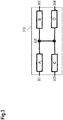
- Figure 3 shows an arrangement 310 with four temperature-dependent resistors A to D.
- the arrangement comprises four terminals 301 to 304, which are connectable to a measuring electronics.
- Resistor A connects terminal 301 to node 305
- resistor B connects terminal 302 to node 305
- resistor C connects terminal 303 to node 305
- resistor D connects terminal 304 to node 305.
- the measuring electronics can have a processing unit (eg an evaluation electronics, a processor, or the like), on the basis of which the four individual resistors A to D can be determined on the basis of the following relationships from the above measurements:
- A R 13 - R 34 + R 14 / 2
- B 2 * R 23 - R 13 - R 34 + R 14 / 2
- C R 13 + R 34 - R 14 / 2
- D R 34 - R 13 + R 14 / 2
- Figure 4 shows an arrangement 410 with five temperature-dependent resistors A to E.
- the arrangement comprises four terminals 401 to 404, which are connectable to a measuring electronics.
- Resistor A connects terminal 401 to node 405
- resistor B connects terminal 402 to node 405
- resistor C connects terminal 403 to node 406, and resistor D connects terminal 404 to node 406.
- a resistor E connects node 405 to node 406.
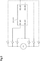
- FIG. 5 shows a schematic circuit of a measuring electronics, by means of which the arrangements 310, 410 can be connected to the measuring unit 111 by means of switches S1 to S6.
- the switches are, for example, electronic switches (eg transistors, relays, mosfets), which can be controlled by the measuring electronics.
- the measuring electronics may have, for example, a controller or processor which, in turn, for the measurements described above, closes the relevant switches, carries out the respective measurement and then closes other switches and carries out the next measurement, etc.
- the resistor R12 can be measured by closing the switch S2 and the switch S6.
- the resistor R13 can be measured by closing the switches S2 and S4.
- the resistor R14 can be measured by closing the switches S2 and S5.
- the resistor R23 can be measured by closing the switches S1 and S4.
- the resistor R34 can be measured by closing the switches S3 and S5.
- the resistor R24 can be measured by closing the switches S1 and S5.
- the other switches are open for the respective measurement.
- series circuits are preferably evaluated from resistors. These approaches are therefore particularly advantageous for determining a lowest temperature of the temperature-dependent resistors.
- the present concept is applicable to any type of resistance measurement. It is not necessary for the resistors used to be particularly temperature dependent (e.g., conventional ohmic resistors may be substituted for NTC or PTC resistors).
Landscapes
- Physics & Mathematics (AREA)
- General Physics & Mathematics (AREA)
- Measuring Temperature Or Quantity Of Heat (AREA)
- Thermistors And Varistors (AREA)
Description
- Die Erfindung betrifft einen Mehrkerntemperaturfühler nach Anspruch 1 sowie ein Verfahren zur Widerstandsbestimmung nach Anspruch 7.
- Es sind Kerntemperaturfühler mit einem Temperaturwiderstand, sogenannte Einpunkt-Kerntemperaturfühler, bekannt. Der hierbei eingesetzte Widerstand ist temperaturabhängig. Üblicherweise wird hierfür ein Heißleiter (auch bezeichnet als NTC-Widerstand) verwendet. Ein solcher Heißleiter hat bei niedriger Temperatur einen hohen Widerstand und bei hoher Temperatur einen niedrigen Widerstand. Auch ist ein sogenannter Kaltleiter (auch bezeichnet als PTC-Widerstand) bekannt, der bei niedriger Temperatur einen geringeren Widerstand als bei hoher Temperatur aufweist.
Aus dem Widerstandswert des Heißleiters oder des Kaltleiters kann die Temperatur des Messfühlers bzw. des Messpunkts am Ort des Messfühlers ermittelt werden.
Der Einpunkt-Kerntemperaturfühler erfordert zur Messung des Temperaturwertes eine zweipolige Verbindung zu einer Messelektronik. - Ferner sind Mehrpunkt-Kerntemperaturfühler bekannt, die mehrere Messpunkte besitzen.
Fig.1 zeigt eine bekannte Schaltungsanordnung mit einer Messelektronik 101 und einem Vierpunkt-Kerntemperaturfühler 102, der über einen von vier Anschlüssen zeitweise mit der Messelektronik 101 verbunden ist. Der Vierpunkt-Kerntemperaturfühler 102 weist vier temperaturabhängige Widerstände 103, 104, 105 und 112 auf, die auf der einen Seite mit Massepotential 106 verbunden sind und jeweils auf der anderen Seite einen Anschluss 107, 108, 109 und 113 aufweisen. Somit wird zur Auswertung der vier Widerstände 103, 104, 105 und 112 eine fünfpolige Steckverbindung (umfassend die Anschlüsse 107, 108, 109 und 113 sowie Massepotential) benötigt. - Für die Messung der Widerstände 103, 104, 105 und 112 wird über einen Schalter 110 jeweils einer der Widerstände 103, 104, 105 und 112 mit einem Messwerk 111 verbunden und der jeweils verbundene Widerstand zwischen Massepotential 106 und dem kontaktierten Anschluss gemessen. Diese Schaltungsanordnung benötigt für einen Vierpunkt-Kerntemperaturfühler 102 eine fünfpolige Steckverbindung zu der Messelektronik 101.
- Nachteilig bei dieser Schaltungsanordnung ist, dass ein aufwendiger fünfpoliger Stecker und eine aufwendige fünfpolige Buchse benötigt werden.
-
Fig.2 zeigt eine ebenfalls bekannte Matrix-Anordnung mit zwei Spalten und zwei Zeilen. Es sind vier Widerstände A bis D gezeigt, die über die Leitungen 201 bis 204 kontaktiert werden können: So kann der Widerstand A über die Leitungen 201 und 203, der Widerstand B über die Leitungen 201 und 204, der Widerstand C über die Leitungen 202 und 203 und der Widerstand D über die Leitungen 202 und 204 bestimmt werden. - Hierbei ist es von Nachteil, dass anhand der Matrix-Anordnung zur Messung von fünf Widerständen insgesamt fünf Leitungen benötigt werden, d.h. analog zu der Darstellung in
Fig.2 zwei Spalten und drei Zeilen oder drei Spalten und zwei Zeilen. -
DE 693 00 966 T2 offenbart einen Temperaturmesser zum Einstecken in ein zu erhitzendes Nahrungsmittel, wobei der Temperaturmesser die Form eines Stabes hat und an seiner Spitze und mindestens einer weiteren Position einen Temperatursensor trägt, deren Widerstand sich mit der Temperatur ändert, der über ein Kabel mit einem Anschluss nach Art eines Telefonsteckers verbunden ist, der über eine korrespondierende in dem Backofen angeordnete Buchse, die für die Wärmebehandlung vorgesehen ist, mit einer Steuereinrichtung zur Steuerung des Heizprozesses verbindbar ist, wobei drei Temperatursensoren vorgesehen sind, die an dem Temperaturmesser an geeigneten voneinander beabstandeten Positionen vorgesehen sind, der Anschluss drei Kontaktbereiche hat und die drei Temperatursensoren miteinander verbunden sind und einen Stern oder Dreieck mit dem drei Ausgängen bilden, die mit den jeweiligen Kontaktbereichen des Anschlusses verbunden sind. Dabei sind die drei Widerstände in Form einer Sternschaltung angeordnet. - Die Aufgabe der Erfindung besteht darin, den vorstehend genannten Nachteil zu vermeiden und insbesondere eine effiziente Möglichkeit zur Kontaktierung eines Mehrpunkt-Temperaturfühlers anzugeben.
Diese Aufgabe wird gemäß den Merkmalen der unabhängigen Patentansprüche gelöst. Weiterbildungen der Erfindung ergeben sich auch aus den abhängigen Ansprüchen.
Zur Lösung der Aufgabe wird ein Mehrkerntemperaturfühler mit fünf temperaturabhängigen Widerständen vorgeschlagen, - bei dem je zwei Widerstände in Reihe geschaltet sind und die Mittenabgriffe der beiden Reihenschaltungen über einen fünften Widerstand miteinander verbunden sind,
- bei dem jedes Ende jeder Reihenschaltung über einen Anschluss mit einer Messelektronik kontaktierbar ist,
- wobei mittels elektronischer Schalter die fünf Widerstände über die Anschlüsse mit der Messelektronik verbindbar sind und
- anhand unterschiedlicher Messungen (insbesondere mittels unterschiedlicher Stellungen der elektronischen Schalter) mittels der Messelektronik die Widerstandswerte der Widerstände bestimmbar sind.
- Bei den elektronischen Schaltern kann es sich um durch die Messelektronik aktivierbare und deaktivierbare Schalter oder Schaltfunktionen handeln. Beispielsweise können Transistoren oder Relais vorgesehen sein, die anhand der Messelektronik angesteuert werden. Beispielsweise kann die Messelektronik eine Prozessor- oder sonstige Verarbeitungseinheit aufweisen, die die elektronischen Schalter ansteuert und die Messwerte bestimmt, z.B. aufnimmt. Aus den Messwerten können dann die Widerstandswerte berechnet werden.
Vorzugsweise sind die Widerstände, z.B. in Form eines Messfühlers, zusammen angeordnet und werden über die Anschlüsse, z.B. eine geeignete Buchse-Stecker-Verbindung, mit der Messelektronik verbunden. Die Messelektronik kann anhand der unterschiedlichen Stellungen der elektronischen Schalter zu verschiedenen Zeiten verschiedene Messungen durchführen, wobei jeweils eine bestimmte Kontaktierung der Widerstände aus der Stellung der elektronischen Schalter resultiert. Aus verschiedenen Kontaktierungen ergeben sich die unterschiedlichen Messungen, die zur Lösung eines Gleichungssystems mit dem Widerstandswerten der Widerstände verwendet werden können. - Die Messelektronik kann eine Verarbeitungseinheit, insbesondere eine Prozessoreinheit und/oder eine zumindest teilweise festverdrahtete oder logische Schaltungsanordnung sein. Die Messelektronik kann insbesondere jede Art von Prozessor oder Rechner oder Computer mit entsprechend notwendiger Peripherie (Speicher, Input/Output-Schnittstellen, Ein-Ausgabe-Geräte, etc.) sein oder umfassen.
- Somit ist es möglich, eine kostengünstige Schaltungsanordnung für die Auswertung eines Mehrpunkt-Kerntemperaturfühlers vorzusehen. Die Kontaktierung bzw. unterschiedliche Beschaltung der mindestens vier Widerstände kann anhand der Anschlüsse z.B. mit einem vierpoligen Stecker und einer vierpoligen Buchse erfolgen, da gemäß dem hier vorliegenden Ansatz fünf Widerstände effizient mit vier Leitungen bestimmt werden können.
- Eine andere Weiterbildung ist es, dass temperaturabhängigen Widerstände Heißleiter oder Kaltleiter sind.
- Hierbei besteht vorteilhaft die Möglichkeit, die kleinste an einem der Widerstände auftretende Temperatur mit hoher Genauigkeit zu ermitteln.
- Auch ist es eine Weiterbildung, dass die Messelektronik über die elektronischen Schalter die Anschlüsse so verbindet, dass die folgenden Messwiderstandswerte R12, R13, R23, R24 und R34 für die fünf Widerstände A, B, C, D und E ermittelbar sind:


- Auch wird die vorstehend genannte Aufgabe gelöst mittels eines Hausgeräts, insbesondere Gargerät oder Ofen, mit einer Kontaktiermöglichkeit für den Mehrkerntemperaturfühler wie hierin beschrieben, wobei die Kontaktiermöglichkeit eine vierpolige Buchse oder einen vierpoligen Stecker umfasst.
- Es ist eine Weiterbildung, dass das Hausgerät mit der Messelektronik ausgerüstet ist, mittels elektronischer Schalter die fünf Widerstände über die Anschlüsse mit der Messelektronik verbindbar sind, und anhand unterschiedlicher Messungen mittels der Messelektronik die Widerstandswerte der Widerstände bestimmbar sind.
- Ferner wird die vorstehend genannte Aufgabe gelöst mittels eines Systems, aufweisend ein Hausgerät wie oben beschrieben und einen Mehrkerntemperaturfühler wie oben beschrieben, wobei die fünf Widerstände über eine vierpolige Buchse-Stecker-Verbindung mit der Messelektronik verbindbar sind.
- Ferner wird die obige Aufgabe gelöst mittels eines Verfahrens zur Widerstandsbestimmung von fünf Widerständen, wobei je zwei Widerstände in Reihe geschaltet sind und die Mittenabgriffe der beiden Reihenschaltungen über einen fünften Widerstand miteinander verbunden sind,
- bei dem die fünf Widerstände über vier Anschlüsse mittels elektronischer Schalter einer Messelektronik elektrisch kontaktiert werden,
- bei dem anhand unterschiedlicher Messungen zu unterschiedlichen Zeitpunkten die Widerstandswerte der fünf Widerstände ermittelt werden.
- Es ist eine Weiterbildung, dass die folgenden Messwiderstandswerte R12, R13, R23, R24 und R34 für die fünf Widerstände A, B, C, D und E ermittelt werden:



- Eine Weiterbildung besteht darin, dass für die ermittelten Widerstandswerte zugehörige Temperaturwerte bestimmt werden.
- Auch ist es eine Ausgestaltung, dass anhand der Temperaturwerte ein Gargerät gesteuert wird.
- Das Verfahren kann beispielsweise in einer Elektronik oder Steuereinheit des Gargeräts implementiert sein.
- Die vorstehenden Ausführungen zu den Vorrichtungen gelten für das hier erwähnte Verfahren entsprechend.
- Die hierin vorgestellte Lösung umfasst ferner ein Computerprogrammprodukt, das direkt in einen Speicher eines digitalen Computers ladbar ist, umfassend Programmcodeteile die dazu geeignet sind, Schritte des hier beschriebenen Verfahrens durchzuführen.
- Weiterhin wird das oben genannte Problem gelöst mittels eines computerlesbaren Speichermediums, z.B. eines beliebigen Speichers, umfassend von einem Computer ausführbare Anweisungen (z.B. in Form von Programmcode) die dazu geeignet sind, dass der Computer Schritte des hier beschriebenen Verfahrens durchführt.
- Die oben beschriebenen Eigenschaften, Merkmale und Vorteile dieser Erfindung sowie die Art und Weise, wie diese erreicht werden, werden klarer und deutlicher verständlich im Zusammenhang mit der folgenden schematischen Beschreibung von Ausführungsbeispielen, die im Zusammenhang mit den Zeichnungen näher erläutert werden. Dabei können zur Übersichtlichkeit gleiche oder gleichwirkende Elemente mit gleichen Bezugszeichen versehen sein.
- Es zeigen:
- Fig.3
- eine nicht zu der Erfindung gehörige Anordnung mit vier temperaturabhängigen Widerständen A bis D, die über vier Anschlüsse mit einer Messelektronik verbindbar sind;
- Fig.4
- eine erfindungsgemäße Anordnung mit fünf temperaturabhängigen Widerständen A bis E, die über vier Anschlüsse mit einer Messelektronik verbindbar sind;
- Fig.5
- eine schematische Schaltung einer Messelektronik, anhand derer die Anordnungen gemäß
Fig.3 undFig.4 jeweils mittels (elektronischer) Schalter mit einem Messwerk verbunden werden können. - Es wird vorgeschlagen, anstatt einer fünfpoligen Verbindung mit einer vierpoligen Verbindung für den Anschluss eines Mehrpunkt-Temperaturfühlers (mit vier oder fünf Messpunkten) auszukommen. Durch den Einsatz eines vierpoligen anstatt eines fünfpoligen Steckers und einer entsprechenden Buchse ergeben sich deutliche Kostenvorteile, reduzierte Anforderungen an Toleranzen sowie geringere Anforderungen an den benötigten Bauraum.
-
Fig.3 zeigt eine Anordnung 310 mit vier temperaturabhängigen Widerständen A bis D. Die Anordnung umfasst vier Anschlüsse 301 bis 304, die mit einer Messelektronik verbindbar sind. Der Widerstand A verbindet den Anschluss 301 mit einem Knoten 305, der Widerstand B verbindet den Anschluss 302 mit dem Knoten 305, der Widerstand C verbindet den Anschluss 303 mit dem Knoten 305 und der Widerstand D verbindet den Anschluss 304 mit dem Knoten 305. - Die Messelektronik (nicht in
Fig.3 dargestellt) verbindet je zwei der Anschlüsse 301 bis 304, so dass nacheinander mehrere Messungen der temperaturabhängigen Widerstände A bis D durchgeführt werden können. Beispielsweise können die folgenden vier Messungen durchgeführt werden: - Messung 1: Die Anschlüsse 301 und 303 werden mit der Messelektronik verbunden. Es wird ein Widerstand R13 gemessen, der einer Reihenschaltung aus den Widerständen A und C entspricht, d.h.

- Messung 2: Die Anschlüsse 301 und 304 werden mit der Messelektronik verbunden. Es wird ein Widerstand R14 gemessen, der einer Reihenschaltung aus den Widerständen A und D entspricht, d.h.

- Messung 3: Die Anschlüsse 302 und 303 werden mit der Messelektronik verbunden. Es wird ein Widerstand R23 gemessen, der einer Reihenschaltung aus den Widerständen B und C entspricht, d.h.

- Messung 4: Die Anschlüsse 303 und 304 werden mit der Messelektronik verbunden. Es wird ein Widerstand R34 gemessen, der einer Reihenschaltung aus den Widerständen C und D entspricht, d.h.

- Die Messelektronik kann eine Verarbeitungseinheit (z.B. eine Auswerteelektronik, einen Prozessor, o.ä.) aufweisen, anhand derer aus den obigen Messungen die vier einzelnen Widerstände A bis D anhand er folgenden Beziehungen ermittelt werden können:



-
Fig.4 zeigt eine Anordnung 410 mit fünf temperaturabhängigen Widerständen A bis E. Die Anordnung umfasst vier Anschlüsse 401 bis 404, die mit einer Messelektronik verbindbar sind. Der Widerstand A verbindet den Anschluss 401 mit einem Knoten 405, der Widerstand B verbindet den Anschluss 402 mit dem Knoten 405, der Widerstand C verbindet den Anschluss 403 mit einem Knoten 406 und der Widerstand D verbindet den Anschluss 404 mit dem Knoten 406. Ein Widerstand E verbindet den Knoten 405 mit dem Knoten 406. - Die Messelektronik (nicht in
Fig.4 dargestellt) verbindet je zwei der Anschlüsse 401 bis 404, so dass nacheinander mehrere Messungen der temperaturabhängigen Widerstände A bis E durchgeführt werden können. Beispielsweise können die folgenden fünf Messungen durchgeführt werden: - Messung 1: Die Anschlüsse 401 und 402 werden mit der Messelektronik verbunden. Es wird ein Widerstand R12 gemessen, der einer Reihenschaltung aus den Widerständen A und B entspricht, d.h.

- Messung 2: Die Anschlüsse 401 und 403 werden mit der Messelektronik verbunden. Es wird ein Widerstand R13 gemessen, der einer Reihenschaltung aus den Widerständen A, E und C entspricht, d.h.

- Messung 3: Die Anschlüsse 402 und 403 werden mit der Messelektronik verbunden. Es wird ein Widerstand R23 gemessen, der einer Reihenschaltung aus den Widerständen B, E und C entspricht, d.h.

- Messung 4: Die Anschlüsse 402 und 404 werden mit der Messelektronik verbunden. Es wird ein Widerstand R24 gemessen, der einer Reihenschaltung aus den Widerständen B, E und D entspricht, d.h.

- Messung 5: Die Anschlüsse 403 und 404 werden mit der Messelektronik verbunden. Es wird ein Widerstand R34 gemessen, der einer Reihenschaltung aus den Widerständen C und D entspricht, d.h.

- Die Messelektronik kann anhand der Verarbeitungseinheit aus den obigen Messungen die fünf einzelnen Widerstände A bis E anhand der folgenden Beziehungen ermitteln:




-
Fig.5 zeigt eine schematische Schaltung einer Messelektronik, anhand derer die Anordnungen 310, 410 mittels Schaltern S1 bis S6 mit dem Messwerk 111 verbunden werden können. Bei den Schaltern handelt es sich beispielsweise um elektronische Schalter (z.B. Transistoren, Relais, Mosfets), die von der Messelektronik ansteuerbar sind. Dazu kann die Messelektronik z.B. einen Kontroller oder Prozessor aufweisen, der der Reihe nach, d.h. für die oben beschriebenen Messungen, die betroffenen Schalter schließt, die jeweilige Messung durchführt und danach andere Schalter schließt und die nächste Messung durchführt, etc. - So kann der Widerstand R12 gemessen werden, indem der Schalter S2 und der Schalter S6 geschlossen werden. Der Widerstand R13 kann gemessen werden, indem die Schalter S2 und S4 geschlossen werden. Der Widerstand R14 kann gemessen werden, indem die Schalter S2 und S5 geschlossen werden. Der Widerstand R23 kann gemessen werden, indem die Schalter S1 und S4 geschlossen werden. Der Widerstand R34 kann gemessen werden, indem die Schalter S3 und S5 geschlossen werden. Der Widerstand R24 kann gemessen werden, indem die Schalter S1 und S5 geschlossen werden.
- Die anderen Schalter sind für die jeweilige Messung offen.
- Hierbei sei angemerkt, dass ein Widerstand Rxy zwischen dem Anschluss x und dem Anschluss y gemessen wird, wobei folgende Zuordnung gilt:
- Anschlüsse 301, 401: x oder y = 1;
- Anschlüsse 302, 402: x oder y = 2;
- Anschlüsse 303, 403: x oder y = 3;
- Anschlüsse 304, 404: x oder y = 4.
- Bei den vorgestellten Lösungen werden vorzugsweise Serienschaltungen aus Widerständen ausgewertet. Diese Lösungsansätze sind daher vor allem von Vorteil zur Ermittlung einer niedrigsten Temperatur der temperaturabhängigen Widerstände.
- Hierbei sei angemerkt, dass das vorliegende Konzept für jede Art der Widerstandsmessung anwendbar ist. Es ist nicht notwendig, dass die eingesetzten Widerstände in besonderem Maße temperaturabhängig sind (z.B. können herkömmliche ohmsche Widerstände anstelle von NTC- oder PTC-Widerständen eingesetzt werden).
- Insbesondere ist es ein Vorteil, dass ein einfacherer und kostengünstiger vierpoliger Stecker für einen Vier- oder Fünfpunkt-Temperaturfühler eingesetzt werden kann. Dies reduziert den erforderlichen Bauraum und vermindert Toleranzprobleme bei SteckerBuchsen-Kombinationen, die eine geringere Anzahl von Polen aufweisen. Weiterhin werden Leitungen eingespart und es müssen weniger Leitungen kontaktiert werden.
-
- 101
- Messelektronik
- 102
- Mehrpunkt-Kerntemperaturfühler
- 103
- temperaturabhängiger Widerstand
- 104
- temperaturabhängiger Widerstand
- 105
- temperaturabhängiger Widerstand
- 112
- temperaturabhängiger Widerstand
- 106
- Massepotential
- 107
- Anschluss
- 108
- Anschluss
- 109
- Anschluss
- 113
- Anschluss
- 110
- Schalter
- 111
- Messwerk
- A
- (temperaturabhängiger) Widerstand, z.B. PTC-Widerstand oder NTC-Widerstand
- B
- (temperaturabhängiger) Widerstand, z.B. PTC-Widerstand oder NTC-Widerstand
- C
- (temperaturabhängiger) Widerstand, z.B. PTC-Widerstand oder NTC-Widerstand
- D
- (temperaturabhängiger) Widerstand, z.B. PTC-Widerstand oder NTC-Widerstand
- E
- (temperaturabhängiger) Widerstand, z.B. PTC-Widerstand oder NTC-Widerstand
- 201-204
- Leitung
- 301
- Anschluss
- 302
- Anschluss
- 303
- Anschluss
- 304
- Anschluss
- 305
- Knoten
- 310
- Anordnung umfassend vier Wiederstände
- 401
- Anschluss
- 402
- Anschluss
- 403
- Anschluss
- 404
- Anschluss
- 405
- Knoten
- 406
- Knoten
- 410
- Anordnung umfassend fünf Wiederstände
- S1-S6
- elektronische Schalter
Claims (10)
- Mehrkerntemperaturfühler umfassend fünf temperaturabhängige Widerstände (A, B, C, D; E), wobei- je zwei Widerstände (A, B; C, D, E) in Reihe geschaltet sind und die Mittenabgriffe (305) der beiden Reihenschaltungen über einen fünften Widerstand (E) miteinander verbunden sind,- jedes Ende jeder Reihenschaltung (401-404) über einen Anschluss (401-404) mit einer Messelektronik kontaktierbar ist,- mittels elektronischer Schalter (S1-S6) die fünf Widerstände (A, B, C, D, E) über die Anschlüsse (401-404) mit der Messelektronik verbindbar sind und- anhand unterschiedlicher Messungen mittels der Messelektronik die Widerstandswerte der Widerstände (A, B; C, D, E) bestimmbar sind.
- Mehrkerntemperaturfühler nach einem der vorhergehenden Ansprüche, wobei die temperaturabhängigen Widerstände (A, B, C, D; E) Heißleiter oder Kaltleiter sind.
- Mehrkerntemperaturfühler nach einem der Ansprüche 1 oder 2, wobei die Messelektronik über die elektronischen Schalter die Anschlüsse so verbindbar sind, dass die folgenden Messwiderstandswerte R12, R13, R23, R24 und R34 für die vier Widerstände A, B, C, D und E ermittelbar sind:


- System, aufweisend einen Mehrkerntemperaturfühler nach einem der Ansprüche 1 bis 3 und ein Hausgerät, insbesondere Gargerät oder Ofen, mit einer Kontaktiermöglichkeit für den Mehrkerntemperaturfühler nach einem der vorhergehenden Ansprüche, wobei- die Kontaktiermöglichkeit eine vierpolige Buchse oder einen vierpoligen Stecker umfasst.
- System nach Anspruch 4, wobei- das Hausgerät mit der Messelektronik ausgerüstet ist,- mittels elektronischer Schalter (S1-S6) die fünf Widerstände (A, B, C, D, E) über die Anschlüsse (401-404) mit der Messelektronik verbindbar sind, und- anhand unterschiedlicher Messungen mittels der Messelektronik die Widerstandswerte der Widerstände (A, B, C, D) bestimmbar sind.
- System nach Anspruch 4 oder 5, wobei die fünf Widerstände (A, B, C, D, E) über eine vierpolige Buchse-Stecker-Verbindung mit der Messelektronik verbindbar sind.
- Verfahren zur Widerstandsbestimmung von fünf Widerständen (A, B, C, D, E), wobei- je zwei Widerstände (A, B, C, D) in Reihe geschaltet sind und die Mittenabgriffe (405, 406) der beiden Reihenschaltungen (A, B, C, D) über einen fünften Widerstand (E) miteinander verbunden sind,- die fünf Widerstände (A-E) über vier Anschlüsse (401-404) mittels elektronischer Schalter (S1-S6) einer Messelektronik elektrisch kontaktiert werden,- bei dem anhand unterschiedlicher Messungen zu unterschiedlichen Zeitpunkten die Widerstandswerte der fünf Widerstände (A-E) ermittelt werden.
- Verfahren nach Anspruch 7, bei dem die folgenden Messwiderstandswerte R12, R13, R23, R24 und R34 für die fünf Widerstände A, B, C, D und E ermittelt werden:



- Verfahren nach einem der Ansprüche 7 oder 8, bei dem für die ermittelten Widerstandswerte zugehörige Temperaturwerte bestimmt werden.
- Verfahren nach Anspruch 9, bei dem anhand der Temperaturwerte ein Gargerät gesteuert wird.
Applications Claiming Priority (1)
| Application Number | Priority Date | Filing Date | Title |
|---|---|---|---|
| DE102011079098A DE102011079098A1 (de) | 2011-07-13 | 2011-07-13 | Widerstandsmessung, insbesondere Temperaturbestimmung anhand temperaturabhängiger Widerstände |
Publications (3)
| Publication Number | Publication Date |
|---|---|
| EP2559981A2 EP2559981A2 (de) | 2013-02-20 |
| EP2559981A3 EP2559981A3 (de) | 2015-04-29 |
| EP2559981B1 true EP2559981B1 (de) | 2018-09-12 |
Family
ID=46466202
Family Applications (1)
| Application Number | Title | Priority Date | Filing Date |
|---|---|---|---|
| EP12174783.6A Active EP2559981B1 (de) | 2011-07-13 | 2012-07-03 | Widerstandsmessung, insbesondere Temperaturbestimmung anhand temperaturabhängiger Widerstände |
Country Status (2)
| Country | Link |
|---|---|
| EP (1) | EP2559981B1 (de) |
| DE (1) | DE102011079098A1 (de) |
Families Citing this family (3)
| Publication number | Priority date | Publication date | Assignee | Title |
|---|---|---|---|---|
| DE102017206407B3 (de) | 2017-04-13 | 2018-07-05 | E.G.O. Elektro-Gerätebau GmbH | Schaltung und Verfahren zur Temperaturmessung und Temperaturfühler |
| FR3101150B1 (fr) * | 2019-09-19 | 2021-10-29 | Continental Automotive Gmbh | Architecture de capteur résistif pour véhicule automobile |
| CN115485833B (zh) * | 2020-11-23 | 2025-12-30 | 北京时代全芯存储技术股份有限公司 | 测试结构以及测试方法 |
Family Cites Families (2)
| Publication number | Priority date | Publication date | Assignee | Title |
|---|---|---|---|---|
| SE469857B (sv) * | 1992-02-07 | 1993-09-27 | Electrolux Ab | Temperaturprob avsedd att införas i en matvara som skall värmebehandlas jämte en ugn för behandling av matvaror innefattande en temperaturprob |
| DE29923215U1 (de) * | 1999-09-20 | 2000-08-03 | RATIONAL AG, 86899 Landsberg | Garprozeßfühler |
-
2011
- 2011-07-13 DE DE102011079098A patent/DE102011079098A1/de not_active Withdrawn
-
2012
- 2012-07-03 EP EP12174783.6A patent/EP2559981B1/de active Active
Non-Patent Citations (1)
| Title |
|---|
| None * |
Also Published As
| Publication number | Publication date |
|---|---|
| EP2559981A3 (de) | 2015-04-29 |
| DE102011079098A1 (de) | 2013-01-17 |
| EP2559981A2 (de) | 2013-02-20 |
Similar Documents
| Publication | Publication Date | Title |
|---|---|---|
| EP2981833B1 (de) | Messwiderstand und entsprechendes messverfahren | |
| DE112016002301B4 (de) | Lenkradgrifferfassungsvorrichtung | |
| EP2675638B1 (de) | Schaltungsanordnung für eine elektrische sitzheizung | |
| DE102020105475A1 (de) | Temperaturmessgerät mit selbständiger Messsondenerkennung | |
| EP2880410B1 (de) | Mehrleitermessvorrichtung zum erfassen eines fehlerhaften, temperaturabhängigen widerstandssensors | |
| DE102010003125B4 (de) | Vorrichtung zur Temperaturmessung | |
| DE102017221612A1 (de) | Stromsensor und Verfahren zum Messen eines elektrischen Stroms | |
| EP3247984B1 (de) | Vorrichtung und verfahren zur temperaturerfassung sowie verwendung der vorrichtung | |
| WO2013124062A2 (de) | Temperaturmess-modul mit lagekompensation | |
| EP2559981A2 (de) | Widerstandsmessung, insbesondere Temperaturbestimmung anhand temperaturabhängiger Widerstände | |
| EP1431768B1 (de) | Verfahren und Vorrichtung zur Widerstandsmessung eines temperaturabhängigen Widerstandselements | |
| DE102009058387A1 (de) | Verfahren und Vorrichtung zur Messung von Leitungswiderständen | |
| EP2559982B1 (de) | System und Verfahren zur Widerstandsbestimmung von drei temperaturabhängigen Widerständen | |
| EP3637116B1 (de) | Sensor und verfahren zur überprüfung eines sensors | |
| WO2006136496A1 (de) | Bestimmung und/oder überwachung der temperatur | |
| WO2011131374A2 (de) | Temperaturüberwachungssystem | |
| EP2639511B1 (de) | Verfahren zum Betreiben eines Gargeräts mit anschließbarem Bratenthermometer und Gargerät | |
| DE102022124708B3 (de) | Leiterplatte zum Einbau in einen Ladesteckverbinder für ein Elektro- oder Hybridfahrzeug, Ladesteckverbinder mit einer solchen Leiterplatte und Anordnung aus einer solchen Leiterplatte und einer zweiten Leiterplatte | |
| EP1879005B1 (de) | Verfahren zur Überprüfung eines Temperatursensors mit mindestens zwei temperatursensitiven Widerständen | |
| EP3058379A1 (de) | Verfahren zum messen einer temperatur | |
| DE102005039573A1 (de) | Schaltungsanordnung zur Erfassung und Auswertung elektrischer und physikalischer Messgrößen in einem elektrischen Schaltgerät | |
| DE10135173A1 (de) | Messvorrichtung, insbesondere für eine Heiz-/Klimaanlage | |
| EP3388802B1 (de) | Schaltung und verfahren zur temperaturmessung und temperaturfühler | |
| DE102007031615A1 (de) | Verfahren zur Überprüfung eines Temperatursensors mit mindestens zwei temperatursensitiven Widerständen | |
| DE102004063207A1 (de) | Temperatursensor |
Legal Events
| Date | Code | Title | Description |
|---|---|---|---|
| PUAI | Public reference made under article 153(3) epc to a published international application that has entered the european phase |
Free format text: ORIGINAL CODE: 0009012 |
|
| AK | Designated contracting states |
Kind code of ref document: A2 Designated state(s): AL AT BE BG CH CY CZ DE DK EE ES FI FR GB GR HR HU IE IS IT LI LT LU LV MC MK MT NL NO PL PT RO RS SE SI SK SM TR |
|
| AX | Request for extension of the european patent |
Extension state: BA ME |
|
| RIN1 | Information on inventor provided before grant (corrected) |
Inventor name: NADLER, ROBERT Inventor name: BAUER, HANS-JUERGEN Inventor name: ROTH, EDUARD |
|
| RAP1 | Party data changed (applicant data changed or rights of an application transferred) |
Owner name: BSH HAUSGERAETE GMBH |
|
| PUAL | Search report despatched |
Free format text: ORIGINAL CODE: 0009013 |
|
| AK | Designated contracting states |
Kind code of ref document: A3 Designated state(s): AL AT BE BG CH CY CZ DE DK EE ES FI FR GB GR HR HU IE IS IT LI LT LU LV MC MK MT NL NO PL PT RO RS SE SI SK SM TR |
|
| AX | Request for extension of the european patent |
Extension state: BA ME |
|
| RIC1 | Information provided on ipc code assigned before grant |
Ipc: G01R 27/08 20060101ALI20150326BHEP Ipc: G01K 7/16 20060101ALI20150326BHEP Ipc: G01R 27/02 20060101ALI20150326BHEP Ipc: G01R 27/14 20060101ALI20150326BHEP Ipc: G01K 1/02 20060101AFI20150326BHEP |
|
| 17P | Request for examination filed |
Effective date: 20151029 |
|
| RBV | Designated contracting states (corrected) |
Designated state(s): AL AT BE BG CH CY CZ DE DK EE ES FI FR GB GR HR HU IE IS IT LI LT LU LV MC MK MT NL NO PL PT RO RS SE SI SK SM TR |
|
| STAA | Information on the status of an ep patent application or granted ep patent |
Free format text: STATUS: EXAMINATION IS IN PROGRESS |
|
| 17Q | First examination report despatched |
Effective date: 20170719 |
|
| GRAP | Despatch of communication of intention to grant a patent |
Free format text: ORIGINAL CODE: EPIDOSNIGR1 |
|
| STAA | Information on the status of an ep patent application or granted ep patent |
Free format text: STATUS: GRANT OF PATENT IS INTENDED |
|
| INTG | Intention to grant announced |
Effective date: 20180405 |
|
| GRAS | Grant fee paid |
Free format text: ORIGINAL CODE: EPIDOSNIGR3 |
|
| GRAA | (expected) grant |
Free format text: ORIGINAL CODE: 0009210 |
|
| STAA | Information on the status of an ep patent application or granted ep patent |
Free format text: STATUS: THE PATENT HAS BEEN GRANTED |
|
| AK | Designated contracting states |
Kind code of ref document: B1 Designated state(s): AL AT BE BG CH CY CZ DE DK EE ES FI FR GB GR HR HU IE IS IT LI LT LU LV MC MK MT NL NO PL PT RO RS SE SI SK SM TR |
|
| REG | Reference to a national code |
Ref country code: GB Ref legal event code: FG4D Free format text: NOT ENGLISH |
|
| REG | Reference to a national code |
Ref country code: CH Ref legal event code: EP |
|
| REG | Reference to a national code |
Ref country code: IE Ref legal event code: FG4D Free format text: LANGUAGE OF EP DOCUMENT: GERMAN |
|
| REG | Reference to a national code |
Ref country code: DE Ref legal event code: R096 Ref document number: 502012013412 Country of ref document: DE |
|
| REG | Reference to a national code |
Ref country code: AT Ref legal event code: REF Ref document number: 1041172 Country of ref document: AT Kind code of ref document: T Effective date: 20181015 |
|
| REG | Reference to a national code |
Ref country code: SE Ref legal event code: TRGR |
|
| REG | Reference to a national code |
Ref country code: NL Ref legal event code: MP Effective date: 20180912 |
|
| REG | Reference to a national code |
Ref country code: LT Ref legal event code: MG4D |
|
| PG25 | Lapsed in a contracting state [announced via postgrant information from national office to epo] |
Ref country code: RS Free format text: LAPSE BECAUSE OF FAILURE TO SUBMIT A TRANSLATION OF THE DESCRIPTION OR TO PAY THE FEE WITHIN THE PRESCRIBED TIME-LIMIT Effective date: 20180912 Ref country code: BG Free format text: LAPSE BECAUSE OF FAILURE TO SUBMIT A TRANSLATION OF THE DESCRIPTION OR TO PAY THE FEE WITHIN THE PRESCRIBED TIME-LIMIT Effective date: 20181212 Ref country code: GR Free format text: LAPSE BECAUSE OF FAILURE TO SUBMIT A TRANSLATION OF THE DESCRIPTION OR TO PAY THE FEE WITHIN THE PRESCRIBED TIME-LIMIT Effective date: 20181213 Ref country code: LT Free format text: LAPSE BECAUSE OF FAILURE TO SUBMIT A TRANSLATION OF THE DESCRIPTION OR TO PAY THE FEE WITHIN THE PRESCRIBED TIME-LIMIT Effective date: 20180912 Ref country code: FI Free format text: LAPSE BECAUSE OF FAILURE TO SUBMIT A TRANSLATION OF THE DESCRIPTION OR TO PAY THE FEE WITHIN THE PRESCRIBED TIME-LIMIT Effective date: 20180912 Ref country code: NO Free format text: LAPSE BECAUSE OF FAILURE TO SUBMIT A TRANSLATION OF THE DESCRIPTION OR TO PAY THE FEE WITHIN THE PRESCRIBED TIME-LIMIT Effective date: 20181212 |
|
| PG25 | Lapsed in a contracting state [announced via postgrant information from national office to epo] |
Ref country code: HR Free format text: LAPSE BECAUSE OF FAILURE TO SUBMIT A TRANSLATION OF THE DESCRIPTION OR TO PAY THE FEE WITHIN THE PRESCRIBED TIME-LIMIT Effective date: 20180912 Ref country code: LV Free format text: LAPSE BECAUSE OF FAILURE TO SUBMIT A TRANSLATION OF THE DESCRIPTION OR TO PAY THE FEE WITHIN THE PRESCRIBED TIME-LIMIT Effective date: 20180912 Ref country code: AL Free format text: LAPSE BECAUSE OF FAILURE TO SUBMIT A TRANSLATION OF THE DESCRIPTION OR TO PAY THE FEE WITHIN THE PRESCRIBED TIME-LIMIT Effective date: 20180912 |
|
| PG25 | Lapsed in a contracting state [announced via postgrant information from national office to epo] |
Ref country code: IT Free format text: LAPSE BECAUSE OF FAILURE TO SUBMIT A TRANSLATION OF THE DESCRIPTION OR TO PAY THE FEE WITHIN THE PRESCRIBED TIME-LIMIT Effective date: 20180912 Ref country code: RO Free format text: LAPSE BECAUSE OF FAILURE TO SUBMIT A TRANSLATION OF THE DESCRIPTION OR TO PAY THE FEE WITHIN THE PRESCRIBED TIME-LIMIT Effective date: 20180912 Ref country code: CZ Free format text: LAPSE BECAUSE OF FAILURE TO SUBMIT A TRANSLATION OF THE DESCRIPTION OR TO PAY THE FEE WITHIN THE PRESCRIBED TIME-LIMIT Effective date: 20180912 Ref country code: EE Free format text: LAPSE BECAUSE OF FAILURE TO SUBMIT A TRANSLATION OF THE DESCRIPTION OR TO PAY THE FEE WITHIN THE PRESCRIBED TIME-LIMIT Effective date: 20180912 Ref country code: IS Free format text: LAPSE BECAUSE OF FAILURE TO SUBMIT A TRANSLATION OF THE DESCRIPTION OR TO PAY THE FEE WITHIN THE PRESCRIBED TIME-LIMIT Effective date: 20190112 Ref country code: NL Free format text: LAPSE BECAUSE OF FAILURE TO SUBMIT A TRANSLATION OF THE DESCRIPTION OR TO PAY THE FEE WITHIN THE PRESCRIBED TIME-LIMIT Effective date: 20180912 Ref country code: ES Free format text: LAPSE BECAUSE OF FAILURE TO SUBMIT A TRANSLATION OF THE DESCRIPTION OR TO PAY THE FEE WITHIN THE PRESCRIBED TIME-LIMIT Effective date: 20180912 Ref country code: PL Free format text: LAPSE BECAUSE OF FAILURE TO SUBMIT A TRANSLATION OF THE DESCRIPTION OR TO PAY THE FEE WITHIN THE PRESCRIBED TIME-LIMIT Effective date: 20180912 |
|
| PG25 | Lapsed in a contracting state [announced via postgrant information from national office to epo] |
Ref country code: SK Free format text: LAPSE BECAUSE OF FAILURE TO SUBMIT A TRANSLATION OF THE DESCRIPTION OR TO PAY THE FEE WITHIN THE PRESCRIBED TIME-LIMIT Effective date: 20180912 Ref country code: PT Free format text: LAPSE BECAUSE OF FAILURE TO SUBMIT A TRANSLATION OF THE DESCRIPTION OR TO PAY THE FEE WITHIN THE PRESCRIBED TIME-LIMIT Effective date: 20190112 Ref country code: SM Free format text: LAPSE BECAUSE OF FAILURE TO SUBMIT A TRANSLATION OF THE DESCRIPTION OR TO PAY THE FEE WITHIN THE PRESCRIBED TIME-LIMIT Effective date: 20180912 |
|
| REG | Reference to a national code |
Ref country code: DE Ref legal event code: R097 Ref document number: 502012013412 Country of ref document: DE |
|
| PLBE | No opposition filed within time limit |
Free format text: ORIGINAL CODE: 0009261 |
|
| STAA | Information on the status of an ep patent application or granted ep patent |
Free format text: STATUS: NO OPPOSITION FILED WITHIN TIME LIMIT |
|
| PG25 | Lapsed in a contracting state [announced via postgrant information from national office to epo] |
Ref country code: DK Free format text: LAPSE BECAUSE OF FAILURE TO SUBMIT A TRANSLATION OF THE DESCRIPTION OR TO PAY THE FEE WITHIN THE PRESCRIBED TIME-LIMIT Effective date: 20180912 |
|
| 26N | No opposition filed |
Effective date: 20190613 |
|
| PG25 | Lapsed in a contracting state [announced via postgrant information from national office to epo] |
Ref country code: SI Free format text: LAPSE BECAUSE OF FAILURE TO SUBMIT A TRANSLATION OF THE DESCRIPTION OR TO PAY THE FEE WITHIN THE PRESCRIBED TIME-LIMIT Effective date: 20180912 |
|
| PGFP | Annual fee paid to national office [announced via postgrant information from national office to epo] |
Ref country code: FR Payment date: 20190724 Year of fee payment: 8 |
|
| PG25 | Lapsed in a contracting state [announced via postgrant information from national office to epo] |
Ref country code: MC Free format text: LAPSE BECAUSE OF FAILURE TO SUBMIT A TRANSLATION OF THE DESCRIPTION OR TO PAY THE FEE WITHIN THE PRESCRIBED TIME-LIMIT Effective date: 20180912 |
|
| REG | Reference to a national code |
Ref country code: CH Ref legal event code: PL |
|
| GBPC | Gb: european patent ceased through non-payment of renewal fee |
Effective date: 20190703 |
|
| PG25 | Lapsed in a contracting state [announced via postgrant information from national office to epo] |
Ref country code: TR Free format text: LAPSE BECAUSE OF FAILURE TO SUBMIT A TRANSLATION OF THE DESCRIPTION OR TO PAY THE FEE WITHIN THE PRESCRIBED TIME-LIMIT Effective date: 20180912 |
|
| REG | Reference to a national code |
Ref country code: BE Ref legal event code: MM Effective date: 20190731 |
|
| PG25 | Lapsed in a contracting state [announced via postgrant information from national office to epo] |
Ref country code: GB Free format text: LAPSE BECAUSE OF NON-PAYMENT OF DUE FEES Effective date: 20190703 |
|
| PG25 | Lapsed in a contracting state [announced via postgrant information from national office to epo] |
Ref country code: LU Free format text: LAPSE BECAUSE OF NON-PAYMENT OF DUE FEES Effective date: 20190703 Ref country code: BE Free format text: LAPSE BECAUSE OF NON-PAYMENT OF DUE FEES Effective date: 20190731 Ref country code: CH Free format text: LAPSE BECAUSE OF NON-PAYMENT OF DUE FEES Effective date: 20190731 Ref country code: LI Free format text: LAPSE BECAUSE OF NON-PAYMENT OF DUE FEES Effective date: 20190731 |
|
| PG25 | Lapsed in a contracting state [announced via postgrant information from national office to epo] |
Ref country code: IE Free format text: LAPSE BECAUSE OF NON-PAYMENT OF DUE FEES Effective date: 20190703 |
|
| REG | Reference to a national code |
Ref country code: AT Ref legal event code: MM01 Ref document number: 1041172 Country of ref document: AT Kind code of ref document: T Effective date: 20190703 |
|
| PG25 | Lapsed in a contracting state [announced via postgrant information from national office to epo] |
Ref country code: AT Free format text: LAPSE BECAUSE OF NON-PAYMENT OF DUE FEES Effective date: 20190703 |
|
| PG25 | Lapsed in a contracting state [announced via postgrant information from national office to epo] |
Ref country code: FR Free format text: LAPSE BECAUSE OF NON-PAYMENT OF DUE FEES Effective date: 20200731 |
|
| PG25 | Lapsed in a contracting state [announced via postgrant information from national office to epo] |
Ref country code: CY Free format text: LAPSE BECAUSE OF FAILURE TO SUBMIT A TRANSLATION OF THE DESCRIPTION OR TO PAY THE FEE WITHIN THE PRESCRIBED TIME-LIMIT Effective date: 20180912 |
|
| PG25 | Lapsed in a contracting state [announced via postgrant information from national office to epo] |
Ref country code: HU Free format text: LAPSE BECAUSE OF FAILURE TO SUBMIT A TRANSLATION OF THE DESCRIPTION OR TO PAY THE FEE WITHIN THE PRESCRIBED TIME-LIMIT; INVALID AB INITIO Effective date: 20120703 Ref country code: MT Free format text: LAPSE BECAUSE OF FAILURE TO SUBMIT A TRANSLATION OF THE DESCRIPTION OR TO PAY THE FEE WITHIN THE PRESCRIBED TIME-LIMIT Effective date: 20180912 |
|
| PG25 | Lapsed in a contracting state [announced via postgrant information from national office to epo] |
Ref country code: MK Free format text: LAPSE BECAUSE OF FAILURE TO SUBMIT A TRANSLATION OF THE DESCRIPTION OR TO PAY THE FEE WITHIN THE PRESCRIBED TIME-LIMIT Effective date: 20180912 |
|
| REG | Reference to a national code |
Ref country code: DE Ref legal event code: R084 Ref document number: 502012013412 Country of ref document: DE |
|
| PGFP | Annual fee paid to national office [announced via postgrant information from national office to epo] |
Ref country code: DE Payment date: 20250731 Year of fee payment: 14 |
|
| PGFP | Annual fee paid to national office [announced via postgrant information from national office to epo] |
Ref country code: SE Payment date: 20250723 Year of fee payment: 14 |