EP2559822B1 - Caisson lumineux à cadre interne mobile - Google Patents
Caisson lumineux à cadre interne mobile Download PDFInfo
- Publication number
- EP2559822B1 EP2559822B1 EP12180700.2A EP12180700A EP2559822B1 EP 2559822 B1 EP2559822 B1 EP 2559822B1 EP 12180700 A EP12180700 A EP 12180700A EP 2559822 B1 EP2559822 B1 EP 2559822B1
- Authority
- EP
- European Patent Office
- Prior art keywords
- inner frame
- box
- envelope
- telescopic
- casing
- Prior art date
- Legal status (The legal status is an assumption and is not a legal conclusion. Google has not performed a legal analysis and makes no representation as to the accuracy of the status listed.)
- Active
Links
Images
Classifications
-
- E—FIXED CONSTRUCTIONS
- E04—BUILDING
- E04B—GENERAL BUILDING CONSTRUCTIONS; WALLS, e.g. PARTITIONS; ROOFS; FLOORS; CEILINGS; INSULATION OR OTHER PROTECTION OF BUILDINGS
- E04B9/00—Ceilings; Construction of ceilings, e.g. false ceilings; Ceiling construction with regard to insulation
- E04B9/003—Ceilings; Construction of ceilings, e.g. false ceilings; Ceiling construction with regard to insulation with movable parts, e.g. pivoting panels, access doors
-
- E—FIXED CONSTRUCTIONS
- E04—BUILDING
- E04B—GENERAL BUILDING CONSTRUCTIONS; WALLS, e.g. PARTITIONS; ROOFS; FLOORS; CEILINGS; INSULATION OR OTHER PROTECTION OF BUILDINGS
- E04B9/00—Ceilings; Construction of ceilings, e.g. false ceilings; Ceiling construction with regard to insulation
- E04B9/006—Ceilings; Construction of ceilings, e.g. false ceilings; Ceiling construction with regard to insulation with means for hanging lighting fixtures or other appliances to the framework of the ceiling
-
- E—FIXED CONSTRUCTIONS
- E04—BUILDING
- E04B—GENERAL BUILDING CONSTRUCTIONS; WALLS, e.g. PARTITIONS; ROOFS; FLOORS; CEILINGS; INSULATION OR OTHER PROTECTION OF BUILDINGS
- E04B9/00—Ceilings; Construction of ceilings, e.g. false ceilings; Ceiling construction with regard to insulation
- E04B9/18—Means for suspending the supporting construction
- E04B9/20—Means for suspending the supporting construction adjustable
-
- E—FIXED CONSTRUCTIONS
- E04—BUILDING
- E04B—GENERAL BUILDING CONSTRUCTIONS; WALLS, e.g. PARTITIONS; ROOFS; FLOORS; CEILINGS; INSULATION OR OTHER PROTECTION OF BUILDINGS
- E04B9/00—Ceilings; Construction of ceilings, e.g. false ceilings; Ceiling construction with regard to insulation
- E04B9/22—Connection of slabs, panels, sheets or the like to the supporting construction
- E04B9/24—Connection of slabs, panels, sheets or the like to the supporting construction with the slabs, panels, sheets or the like positioned on the upperside of, or held against the underside of the horizontal flanges of the supporting construction or accessory means connected thereto
- E04B9/247—Connection of slabs, panels, sheets or the like to the supporting construction with the slabs, panels, sheets or the like positioned on the upperside of, or held against the underside of the horizontal flanges of the supporting construction or accessory means connected thereto by means of sliding or pivoting locking elements, held against the underside of the supporting construction
-
- E—FIXED CONSTRUCTIONS
- E04—BUILDING
- E04B—GENERAL BUILDING CONSTRUCTIONS; WALLS, e.g. PARTITIONS; ROOFS; FLOORS; CEILINGS; INSULATION OR OTHER PROTECTION OF BUILDINGS
- E04B9/00—Ceilings; Construction of ceilings, e.g. false ceilings; Ceiling construction with regard to insulation
- E04B9/04—Ceilings; Construction of ceilings, e.g. false ceilings; Ceiling construction with regard to insulation comprising slabs, panels, sheets or the like
- E04B2009/0492—Ceilings; Construction of ceilings, e.g. false ceilings; Ceiling construction with regard to insulation comprising slabs, panels, sheets or the like with fabrics tensioned on frames
Definitions
- the present invention relates to a preferably light box with movable internal frame.
- This light box is intended to be integrated in a false wall type false ceiling.
- the luminous preference boxes comprise an internal frame provided with at least one stretched sheet attached to the base of said inner frame, an envelope intended to be fixed to a wall and comprising an outer frame and a bottom, and a set hinge connecting the inner frame and the casing so as to allow tilting of said inner frame relative to the casing of the box.
- the envelope may be equipped with lighting means and the sheet may be of the translucent type.
- the box may further comprise, in a known manner, stiffening elements to reinforce its rigidity.
- the inner frame is movable relative to the casing of the box .
- the internal frame may for example be articulated with respect to the casing of the box. It is already known to articulate an internal frame with respect to the envelope such as that described in the document FR 2 911 619 .
- This articulation comprises a first portion mounted on one face of said inner frame facing the bottom of the envelope and a second portion fixed on said bottom and pivoting relative to the first part.
- said articulation has several disadvantages. Thus, insofar as the second part is fixed on said bottom, it is clear that maintenance access to the fluorescent tubes located near said second part is difficult.
- the inner frame comprises a plurality of flexible plies
- said inner frame therefore has a large thickness and it is understood that it is necessary to leave a large clearance between the casing and the internal frame to allow the opening of the box by rotating the internal frame.
- This too important game is unsightly and must be filled by large flexible joints to prevent dust from behind the false ceiling falling into the room under said false ceiling.
- the rotation of the internal frame may be incomplete or impossible.
- the object of the present invention is therefore to overcome the aforementioned drawbacks and to propose a solution making it possible to easily and securely, in particular for maintenance operations, the opening of a box that can be arranged at the door. plumb objects high and have a thick internal frame without having too much play around said internal frame.
- a box intended to be integrated in a false wall type false ceiling comprising a movable internal frame at the base of which is fixed at least one stretched sheet, an envelope for receive said internal frame and at least one mechanism connecting said inner frame to said envelope.
- Said box is remarkable in that the mechanism allows a movement of said inner frame relative to said envelope, successively combining a substantially vertical translation phase and a substantially horizontal translation phase.
- This movement is accomplished by means of a mechanism which comprises at least one telescopic support adapted to extend along a substantially vertical axis and fixed at its upper end to the casing of the box and secured to its lower end of the internal frame by a link "slide".
- the mechanism comprises at least one telescopic support connecting two opposite sides of the inner frame to the casing, said telescopic supports being placed in the vertical plane containing the center of gravity of the internal frame.
- the mechanism comprises two telescopic supports connecting two opposite sides of the inner frame to the casing, said telescopic supports being disposed symmetrically on either side of the vertical plane containing the center of gravity of the internal frame.
- the two telescopic supports of each of the two opposite sides of the inner frame are preferably separated by a distance less than a quarter of the length of said opposite side.
- the inner frame comprises on its upper face a longitudinal groove in the general shape of inverted T and the lower end of each telescopic support comprises a slide adapted to cooperate with said groove to allow sliding in a horizontal plane of the internal frame by compared to the telescopic support.
- the box is provided with guide members disposed on the periphery of the internal frame and a seal on the periphery of the inner frame and comprises at least one fastener type bolt.
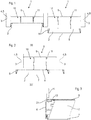
- the casing 1 with internal frame 2 mobile comprises a casing 3 intended to receive said internal frame 2.
- the inner frame 2 is, in operation, housed in the casing 3 of the casing 1, as shown in the leftmost view of the figure 1 and is, especially for maintenance, completely out of the envelope 3, as shown on the figure 2 .
- the most right view of the figure 1 represents the internal frame 2 during movement.
- the envelope 3 is preferably formed by different elements 4 defining generally the four sides 5 of a quadrilateral on which is advantageously mounted a bottom (not shown).
- This envelope 3 is intended to be preferably integrated in a false wall false ceiling type.
- Said elements 4 and the bottom forming the envelope 3 are advantageously, as in this example, made of structural elements, metal or not, the ceiling of the room receiving the false ceiling.
- these elements 4 and the bottom may, for example, be independent profiles bent sheet without departing from the scope of the present invention.
- the inner frame 2 is formed by a rail 6 itself consisting of abutting profiles on which is fixed at least a first flexible sheet 7 stretched.
- Smooth is an organ well known to those skilled in the art in the field of stretched false ceilings which is commonly used to maintain the flexible sheet of a suspended false ceiling.
- the inner frame 2 may be equipped with a second flexible ply 8 stretched above the first flexible ply 7.
- the first flexible ply 7 is translucent and the second flexible ply 8 is transparent. The latter has in particular the role of protecting the first flexible sheet 7 against dust and insects that could be deposited on it and which would then be visible by the users located in the room under said first flexible ply 7.
- the box 1 further comprises, to stiffen the inner frame 2, stiffening means (not shown) formed of at least one spar extending between two opposite profiles of the rail 6 of said inner frame 2 .
- the box 1 further comprises lighting means (not shown), such as neon tubes, advantageously mounted on the bottom of the envelope 3 said box 1.
- lighting means such as neon tubes
- said lighting means may be fixed on the "true ceiling" of the room receiving the false ceiling, without departing from the scope of the present invention.
- the inner frame 2 is movable by a movement successively combining a substantially vertical translation phase and a substantially horizontal translation phase.
- said box 1 comprises a mechanism 10 comprising at least one telescopic support 11 connecting two opposite sides of the inner frame 2 to the casing 3.
- the connection of the telescopic support 11 to the casing 3 can be performed using a support member 9 disposed within the casing 3.
- these two telescopic supports 11 are placed in the vertical plane containing the center of gravity of the internal framework 2.
- the mechanism 10 comprises two telescopic supports 11 connecting two opposite sides of the inner frame 2 to the envelope 3 and being arranged symmetrically on either side of the vertical plane containing the center of severity of the internal framework 2.
- Each telescopic support 11 is able to extend along a substantially vertical axis, it is fixed at its upper end to the casing 3 of the casing 1 and is secured at its lower end of the inner frame 2 by a "slide" connection.
- the inner frame 2 comprises on its upper face a longitudinal groove 21 in the general shape of inverted T, and the lower end of each telescopic support 11 comprises a slider 12 adapted to cooperate with said groove 21 to allow sliding in a substantially horizontal plane of the inner frame 2 relative to the telescopic support 11.
- the skilled person can easily replace the groove 21 and the slider 12 for any other suitable means such as, for example, an I-shaped rail and a rolling member without departing the frame of the present invention.
- the two telescopic supports 11 of each of the two opposite sides of the inner frame 2 are preferably spaced apart by a distance less than a quarter of the length of said opposite side.
- the casing 1 is advantageously provided with guide members (not shown) disposed on the periphery of the inner frame 2 to facilitate the repositioning of the internal frame inside the casing 3 of the box 1 during the vertical translation, said guide members preferably being rollers or balls.
- the casing 1 preferably comprises at least one closure (not shown) of the bolt type for example.
- the mechanism 10 may comprise only one central telescopic support 11 connecting the center of the bottom of the casing 3 to the two opposite sides of the inner frame 2, the telescopic support 11 then comprising an additional horizontal support connecting said two opposite sides of the inner frame 2.
- this variant is not satisfactory for reasons of stability but especially because the telescopic support 11 disposed in the box 1 in a central position hinders access to the the interior of the casing 1 and therefore makes maintenance difficult.
- the inner frame 2 is vertically translated through the telescopic supports 11 (Cf. figure 1 ); then, when the inner frame 2 is completely clear of the casing 3, the telescopic supports 11 being at the end of the stroke, it is then possible to translate the inner frame 2 in a horizontal plane on one side or the other of the envelope 3 in order to clear successively the entire lower surface of the casing 1, facilitating access to all the equipment contained in said box 1.
- the inner frame 2 is shown translated on one side (in bold line) and on the other (partially dotted) of the envelope 3.
- the casing 1 with internal frame 2 mobile according to the invention is preferably intended to be integrated alone to a false wall false ceiling type.
- said box 1 can obviously be arranged next to boxes of the same type, so as to form a lighting matrix.
- the box 1 according to the invention is light and simple construction, and that the inner frame 2 can be easily moved regardless of its dimensions.
Landscapes
- Engineering & Computer Science (AREA)
- Architecture (AREA)
- Physics & Mathematics (AREA)
- Electromagnetism (AREA)
- Civil Engineering (AREA)
- Structural Engineering (AREA)
- Casings For Electric Apparatus (AREA)
- Tents Or Canopies (AREA)
- Non-Portable Lighting Devices Or Systems Thereof (AREA)
Description
- La présente invention concerne un caisson de préférence lumineux à cadre interne mobile. Ce caisson lumineux est destiné à être intégré à une fausse paroi de type faux plafond.
- De manière classique, les caissons de préférence lumineux comprennent un cadre interne muni au moins d'une nappe tendue fixée à la base dudit cadre interne, une enveloppe destinée à être fixée à une paroi et comportant un cadre externe et un fond, et un ensemble charnière reliant le cadre interne et l'enveloppe de manière à permettre un basculement dudit cadre interne par rapport à l'enveloppe du caisson.
- En particulier, l'enveloppe peut être équipée de moyens d'éclairage et la nappe peut être du type translucide. Le caisson peut encore comprendre, de manière connue, des éléments raidisseurs pour renforcer sa rigidité.
- Pour permettre les opérations de maintenance, tant de la face interne de la nappe tendue (nettoyage) que celle des moyens d'éclairage (nettoyage et échange des tubes fluorescents par exemple), le cadre interne est mobile par rapport à l'enveloppe du caisson.
- A cet égard, le cadre interne peut par exemple être articulé par rapport à l'enveloppe du caisson. On connaît déjà une articulation d'un cadre interne par rapport à l'enveloppe telle que celle décrite dans le document
FR 2 911 619 - Le but de la présente invention est donc de pallier les inconvénients précédemment cités et de proposer une solution permettant de réaliser de façon aisée et en toute sécurité, notamment pour des opérations de maintenance, l'ouverture d'un caisson pouvant être disposée à l'aplomb d'objets de grande hauteur et comporter un cadre interne de grande épaisseur sans devoir laisser un jeu trop important autour dudit cadre interne.
- Conformément à l'invention selon la revendication 1, il est donc proposé un caisson destiné à être intégré à une fausse paroi de type faux plafond, comprenant un cadre interne mobile à la base duquel est fixée au moins une nappe tendue, une enveloppe destinée à recevoir ledit cadre interne et au moins un mécanisme reliant ledit cadre interne à ladite enveloppe. Ledit caisson est remarquable en ce que le mécanisme permet un mouvement dudit cadre interne par rapport à ladite enveloppe, combinant successivement une phase de translation sensiblement verticale et une phase de translation sensiblement horizontale.
- Ce mouvement est accompli au moyen d'un mécanisme qui comprend au moins un support télescopique apte à s'étendre selon un axe sensiblement vertical et fixé à son extrémité supérieure à l'enveloppe du caisson et solidaire à son extrémité inférieure du cadre interne par une liaison "glissière".
- Selon un mode de réalisation préférentiel, le mécanisme comprend au moins un support télescopique reliant deux cotés opposés du cadre interne à l'enveloppe, lesdits supports télescopiques étant placés dans le plan vertical contenant le centre de gravité du cadre interne.
- Selon un mode de réalisation encore plus avantageux, le mécanisme comprend deux supports télescopiques reliant deux cotés opposés du cadre interne à l'enveloppe, lesdits supports télescopiques étant disposés symétriquement de part et d'autre du plan vertical contenant le centre de gravité du cadre interne. Les deux supports télescopiques de chacun des deux cotés opposés du cadre interne sont de préférence écartés d'une distance inférieure au quart de la longueur dudit coté opposé.
- De préférence, le cadre interne comporte sur sa face supérieure une rainure longitudinale en forme générale de T inversé et l'extrémité inférieure de chaque support télescopique comporte un coulisseau apte à coopérer avec ladite rainure pour permettre le coulissement dans un plan horizontal du cadre interne par rapport au support télescopique.
- Avantageusement, le caisson est muni d'organes de guidage disposés sur la périphérie du cadre interne et d'un joint sur le pourtour du cadre interne et comporte au moins une fermeture de type à targette.
- D'autres avantages et caractéristiques ressortiront mieux de la description qui va suivre d'une variante d'exécution d'un caisson à cadre interne mobile selon l'invention en référence aux figures annexées sur lesquelles :
- la
figure 1 est une série de vues en coupe verticale d'un caisson à cadre interne mobile selon l'invention, lors de la première phase du mouvement dudit cadre interne ; - la
figure 2 est une série de vues en coupe verticale d'un caisson à cadre interne mobile de lafigure 1 , lors de la deuxième phase du mouvement dudit cadre interne ; - la
figure 3 est une vue en coupe verticale agrandie partielle de lafigure 2 selon l'axe III-III' de lafigure 2 . - En référence aux
figures 1 à 3 , le caisson 1 à cadre interne 2 mobile selon l'invention comprend une enveloppe 3 destinée à recevoir ledit cadre interne 2. - Le cadre interne 2 est, en fonctionnement, logé dans l'enveloppe 3 du caisson 1, comme représenté sur la vue la plus à gauche de la
figure 1 et est, notamment pour la maintenance, entièrement sorti hors de l'enveloppe 3, comme représenté sur lafigure 2 . La vue la plus à droite de lafigure 1 représente le cadre interne 2 en cours de mouvement. - L'enveloppe 3 est de préférence formée par différents éléments 4 définissants globalement les quatre côtés 5 d'un quadrilatère sur lequel est avantageusement monté un fond (non représenté). Cette enveloppe 3 est destinée à être de préférence intégrée à une fausse paroi de type faux plafond. Lesdits éléments 4 et le fond formant l'enveloppe 3 sont avantageusement, comme dans cet exemple, constitués des éléments de structure, métalliques ou non, du plafond du local recevant le faux plafond. Toutefois, ces éléments 4 et le fond pourront, par exemple, être des profilés indépendants en tôle pliée, sans sortir du cadre de la présente invention.
- Le cadre interne 2 est formé par une lisse 6 elle-même constituée de profils aboutés sur lesquels est fixée au moins une première nappe souple 7 tendue. La lisse est un organe bien connu de l'Homme du Métier dans le domaine des faux plafonds tendus qui est utilisée couramment pour maintenir la nappe souple d'un faux plafond tendu.
- Dans la configuration représentée sur les
figures 1 à 3 , le cadre interne 2 peut être équipé d'une seconde nappe souple 8 tendue située au-dessus de la première nappe souple 7. Par exemple, la première nappe souple 7 est translucide et la deuxième nappe souple 8 est transparente. Cette dernière a notamment pour rôle de protéger la première nappe souple 7 contre les poussières et les insectes qui pourraient se déposer sur celle-ci et qui seraient alors visibles par les usagers situés dans le local sous ladite première nappe souple 7. - Dans un mode de réalisation préférentiel, le caisson 1 comprend en outre, pour rigidifier le cadre interne 2, des moyens raidisseurs (non représentés) formés d'au moins un longeron s'étendant entre deux profils opposés de la lisse 6 dudit cadre interne 2.
- De préférence, le caisson 1 comprend encore des moyens d'éclairage (non représentés), tels que des tubes néons, avantageusement montés sur le fond de l'enveloppe 3 dudit caisson 1. Toutefois, en l'absence de fond, lesdits moyens d'éclairage pourront être fixés sur le "vrai plafond" du local recevant le faux plafond, sans sortir du cadre de la présente invention.
- Le cadre interne 2 est mobile par un mouvement combinant successivement une phase de translation sensiblement verticale et une phase de translation sensiblement horizontal.
- On comprend bien que les termes "horizontal" et "vertical" désignent des directions respectivement parallèle et perpendiculaire au faux plafond lorsque celui-ci est horizontal. Il va de soi que ces termes seront à adapter si le faux plafond et donc le cadre interne 2 sont inclinés voire au moins en partie verticaux.
- De même, dans cette description, on suppose que le cadre interne 2 du caisson 1 est disposé horizontalement. Les expressions "supérieure" et "inférieure" utilisées ici se rapportent donc à des positions relatives par rapport au sens vertical. Plus généralement, par exemple dans le cas d'un caisson 1 et d'un cadre interne 2 fixés inclinés ou verticalement, il convient d'interpréter "supérieure" et "inférieure" respectivement dans le sens "proche de la fausse paroi" et "éloigné de la fausse paroi".
- En référence aux
figures 1 à 3 , pour assurer le double mouvement du cadre interne 2, ledit caisson 1 comporte un mécanisme 10 comprenant au moins un support télescopique 11 reliant deux cotés opposés du cadre interne 2 à l'enveloppe 3. La liaison du support télescopique 11 à l'enveloppe 3 pourra être réalisée à l'aide d'un élément support 9 disposé à l'intérieur de l'enveloppe 3. Pour des raisons évidentes d'équilibre lors de la translation verticale, ces deux supports télescopiques 11 sont placés dans le plan vertical contenant le centre de gravité du cadre interne 2. - Avantageusement, pour des questions de stabilité lors des différentes translations, le mécanisme 10 comporte deux supports télescopiques 11 reliant deux cotés opposés du cadre interne 2 à l'enveloppe 3 et étant disposés symétriquement de part et d'autre du plan vertical contenant le centre de gravité du cadre interne 2.
- Chaque support télescopique 11 est apte à s'étendre selon un axe sensiblement vertical, il est fixé à son extrémité supérieure à l'enveloppe 3 du caisson 1 et il est solidaire à son extrémité inférieure du cadre interne 2 par une liaison "glissière".
- De préférence, conformément à la
figure 3 , pour assurer cette liaison "glissière", le cadre interne 2 comporte sur sa face supérieure une rainure 21 longitudinale en forme générale de T inversé, et l'extrémité inférieure de chaque support télescopique 11 comporte un coulisseau 12 apte à coopérer avec ladite rainure 21 pour permettre le coulissement dans un plan sensiblement horizontal du cadre interne 2 par rapport au support télescopique 11. - Pour assurer cette liaison "glissière", l'Homme du Métier pourra sans difficulté remplacer la rainure 21 et le coulisseau 12 pour tout autre moyen adapté tel que, par exemple, un rail en forme de I et un organe de roulement sans sortir du cadre de la présente invention.
- Pour permettre l'accès à presque tout l'intérieur du caisson 1, les deux supports télescopiques 11 de chacun des deux cotés opposés du cadre interne 2 sont de préférence écartés d'une distance inférieure au quart de la longueur dudit coté opposé.
- Par ailleurs, le caisson 1 est avantageusement muni d'organes de guidage (non représentés) disposés sur la périphérie du cadre interne 2 pour faciliter la remise en place du cadre interne à l'intérieur de l'enveloppe 3 du caisson 1 lors de la translation verticale, lesdits organes de guidage étant de préférence des roulettes ou des billes.
- En outre, pour assurer l'étanchéité entre le cadre interne 2 et l'enveloppe 3, on pourra sans difficulté mettre en place un joint (non représentés) par exemple sous forme de balai sur le pourtour du cadre interne 2.
- Enfin, pour maintenir le cadre interne 2 en position de fermeture dite de fonctionnement (Cf. la vue la plus à gauche de la
figure 1 ), le caisson 1 comporte de préférence au moins une fermeture (non représentée) de type à targette par exemple. - Enfin, on comprend bien que le mécanisme 10 pourra ne comporter qu'un seul support télescopique 11 central reliant le centre du fond de l'enveloppe 3 aux deux cotés opposés du cadre interne 2, le support télescopique 11 comprenant alors un support additionnel horizontal reliant lesdits deux cotés opposés du cadre interne 2. Toutefois, on comprend bien que cette variante n'est pas satisfaisante pour des raisons de stabilité mais surtout parce que le support télescopique 11 disposé dans le caisson 1 dans une position centrale gêne l'accès à l'intérieur du caisson 1 et rend par conséquent délicate la maintenance.
- Ainsi avec une configuration telle que décrite précédemment et en référence aux
figures 1 et 2 , pour ouvrir le caisson 1 et faire sortir le cadre interne 2 de l'enveloppe 3, on fait translater verticalement le cadre interne 2 grâce aux supports télescopiques 11 (Cf.figure 1 ) ; puis, lorsque le cadre interne 2 est entièrement dégagé de l'enveloppe 3, les supports télescopiques 11 étant en fin de course, on peut faire alors translater le cadre interne 2 dans un plan horizontal d'un coté ou de l'autre de l'enveloppe 3 afin de dégager successivement toute la surface inférieure du caisson 1, facilitant l'accès à tous les équipements contenus dans ledit caisson 1. Sur lafigure 2 , on a représenté le cadre interne 2 translaté d'un coté (en trait fort) et de l'autre (partiellement en pointillé) de l'enveloppe 3. - Dans cette configuration, après la translation verticale, on comprend bien que le cadre interne 2 se déplace horizontalement parallèlement au faux plafond et que cette translation horizontale du cadre interne 2 peut être réalisée dans un espace réduit et donc même à l'aplomb d'objets de grande hauteur. En effet, l'espace nécessaire à cette translation horizontale doit être au minimum légèrement plus grand que l'épaisseur dudit cadre interne 2.
- Le caisson 1 à cadre interne 2 mobile selon l'invention est de préférence destiné à être intégré seul à une fausse paroi de type faux plafond. Toutefois, ledit caisson 1 peut évidemment être disposé à côté de caissons du même type, de façon à constituer une matrice d'éclairage. En outre, il ressort clairement de la description que le caisson 1 selon l'invention est de construction légère et simple, et que le cadre interne 2 peut être facilement déplacé quelles que soient ses dimensions.
Claims (8)
- Caisson (1) destiné à être intégré à une fausse paroi de type faux plafond, comprenant un cadre interne (2) mobile à la base duquel est fixée au moins une nappe tendue (7, 8), une enveloppe (3) destinée à recevoir ledit cadre interne (2) et au moins un mécanisme (10) reliant ledit cadre interne (2) à ladite enveloppe (3), ledit caisson (1) étant caractérisé en ce que le mécanisme (10) comprend au moins un support télescopique (11) apte à s'étendre selon un axe sensiblement vertical et fixé à son extrémité supérieure à l'enveloppe (3) du caisson (1) et solidaire à son extrémité inférieure du cadre interne (2) par une liaison "glissière" de manière à ce que le cadre interne (2) passe d'une position de fonctionnement dans laquelle il est logé dans l'enveloppe (3) à une position de maintenance dans laquelle il est entièrement sorti de l'enveloppe (3) par un mouvement dudit cadre interne (2) par rapport à ladite enveloppe (3), combinant successivement une phase de translation sensiblement verticale et une phase de translation sensiblement horizontale.
- Caisson (1) selon la revendication 1, caractérisé en ce que le mécanisme (10) comprend au moins un support télescopique (11) reliant deux cotés opposés du cadre interne (2) à l'enveloppe (3), lesdits supports télescopiques (11) étant placés dans le plan vertical contenant le centre de gravité du cadre interne (2).
- Caisson (1) selon la revendication 2, caractérisé en ce que le mécanisme (10) comprend deux supports télescopiques (11) reliant deux cotés opposés du cadre interne (2) à l'enveloppe (3), lesdits supports télescopiques (11) étant disposés symétriquement de part et d'autre du plan vertical contenant le centre de gravité du cadre interne (2).
- Caisson (1) selon la revendication 3, caractérisé en ce que les deux supports télescopiques (11) de chacun des deux cotés opposés du cadre interne (2) sont écartés d'une distance inférieure au quart de la longueur dudit coté opposé.
- Caisson (1) selon l'une quelconque des revendications là 4, caractérisé en ce que le cadre interne (2) comporte sur sa face supérieure une rainure (21) longitudinale en forme générale de T inversé et en ce que l'extrémité inférieure de chaque support télescopique (11) comporte un coulisseau (12) apte à coopérer avec ladite rainure (21) pour permettre le coulissement dans un plan horizontal du cadre interne (2) par rapport au support télescopique (11).
- Caisson (1) selon l'une quelconque des revendications précédentes, caractérisé en ce que le caisson (1) est muni d'organes de guidage disposés sur la périphérie du cadre interne (2).
- Caisson (1) selon l'une quelconque des revendications précédentes, caractérisé en ce que le caisson (1) est muni d'un joint sur le pourtour du cadre interne (2).
- Caisson (1) selon l'une quelconque des revendications précédentes, caractérisé en ce que le caisson (1) comporte au moins une fermeture de type à targette.
Applications Claiming Priority (1)
| Application Number | Priority Date | Filing Date | Title |
|---|---|---|---|
| FR1102531A FR2979116B1 (fr) | 2011-08-17 | 2011-08-17 | Caisson lumineux a cadre mobile. |
Publications (2)
| Publication Number | Publication Date |
|---|---|
| EP2559822A1 EP2559822A1 (fr) | 2013-02-20 |
| EP2559822B1 true EP2559822B1 (fr) | 2018-12-12 |
Family
ID=46642449
Family Applications (1)
| Application Number | Title | Priority Date | Filing Date |
|---|---|---|---|
| EP12180700.2A Active EP2559822B1 (fr) | 2011-08-17 | 2012-08-16 | Caisson lumineux à cadre interne mobile |
Country Status (2)
| Country | Link |
|---|---|
| EP (1) | EP2559822B1 (fr) |
| FR (1) | FR2979116B1 (fr) |
Cited By (2)
| Publication number | Priority date | Publication date | Assignee | Title |
|---|---|---|---|---|
| RU203036U1 (ru) * | 2020-11-30 | 2021-03-18 | Алексей Алексеевич Сатаров | Профиль для монтажа натяжного потолка |
| RU2809371C1 (ru) * | 2023-10-03 | 2023-12-11 | Алексей Михайлович Леготкин | Узел крепления для монтажа многоуровневого натяжного потолка |
Families Citing this family (2)
| Publication number | Priority date | Publication date | Assignee | Title |
|---|---|---|---|---|
| FR3010424B1 (fr) * | 2013-09-10 | 2015-09-25 | Normalu | <p>systeme de fixation pour la realisation de revetements tendus</p> |
| FR3140638A1 (fr) * | 2022-10-05 | 2024-04-12 | Newmat | Elément profilé pour dalle à toile tendue et dalle comprenant un tel élément profilé |
Family Cites Families (3)
| Publication number | Priority date | Publication date | Assignee | Title |
|---|---|---|---|---|
| DE2927166A1 (de) * | 1979-07-05 | 1981-01-08 | Hermann J Kleine | Deckenverkleidung mit mindestens einer deckenplatte oder -tafel bzw. einem deckenpaneel |
| EP1559846B1 (fr) * | 2004-01-28 | 2009-02-04 | Soft Cells A/S | Panneaux et systèmes de tels panneaux dans un faux plafond |
| FR2911619B1 (fr) * | 2007-01-24 | 2010-12-31 | Normalu | Dispositif a caisson mobile. |
-
2011
- 2011-08-17 FR FR1102531A patent/FR2979116B1/fr active Active
-
2012
- 2012-08-16 EP EP12180700.2A patent/EP2559822B1/fr active Active
Non-Patent Citations (1)
| Title |
|---|
| None * |
Cited By (2)
| Publication number | Priority date | Publication date | Assignee | Title |
|---|---|---|---|---|
| RU203036U1 (ru) * | 2020-11-30 | 2021-03-18 | Алексей Алексеевич Сатаров | Профиль для монтажа натяжного потолка |
| RU2809371C1 (ru) * | 2023-10-03 | 2023-12-11 | Алексей Михайлович Леготкин | Узел крепления для монтажа многоуровневого натяжного потолка |
Also Published As
| Publication number | Publication date |
|---|---|
| FR2979116A1 (fr) | 2013-02-22 |
| EP2559822A1 (fr) | 2013-02-20 |
| FR2979116B1 (fr) | 2016-12-09 |
Similar Documents
| Publication | Publication Date | Title |
|---|---|---|
| FR2975420A1 (fr) | Dispositif d'obturation au moins partielle d'une cavite ouverte par le dessus | |
| CA2783706A1 (fr) | Mecanisme d'articulation frangible pour une cloison de plateforme, cloison, ensemble et procede associes | |
| CA2598500C (fr) | Caisson a raidisseur invisible | |
| EP2401443B1 (fr) | Caisson lumineux a ouverture roto-translative | |
| EP2559822A1 (fr) | Caisson lumineux à cadre interne mobile | |
| FR2970019A1 (fr) | Caisson lumineux a charniere a bras telescopique | |
| EP2494121B3 (fr) | Dispositif de fausse paroi | |
| EP1400653A1 (fr) | Fenêtre ou porte-fenêtre, coulissante à vantaux blocables en appui étanche sur le dormant | |
| FR2942489A1 (fr) | Caisson lumineux a ouverture compas a ressort | |
| EP2904176B1 (fr) | Abri pour bassin d'agrément | |
| FR2804984A1 (fr) | Systeme d'echafaudage pour capacites de formes diverses | |
| EP2313593B1 (fr) | Porte pour abri de piscine | |
| FR2581303A1 (fr) | Structure de vitrine | |
| FR2974132A1 (fr) | Dispositif pour le basculement d'au moins un caisson mobile monte sur une paroi telle qu'un mur ou un plafond. | |
| EP3400622A1 (fr) | Abri stationnaire de stockage d'au moins une unité de stockage d'énergie électrique | |
| FR3102452A1 (fr) | Caisson comprenant une porte de type accordeon a multiples panneaux pour un vehicule automobile | |
| EP3400190B1 (fr) | Abri stationnaire de stockage d'au moins une unité de stockage d'énergie électrique | |
| FR3020649A1 (fr) | Abri de piscine a modules telescopiques comprenant un mecanisme de deplacement ameliore des modules | |
| EP3830643A1 (fr) | Dispositif de prise de plan produit | |
| FR2957375A1 (fr) | Abri de piscine compose de plusieurs modules | |
| CA1071930A (fr) | Caisse d'echange a volet de condamnation notamment pour les comptoirs a guichet | |
| EP2505054B1 (fr) | Cloison montante et pivotante | |
| FR2614341A1 (fr) | Perfectionnements aux plates-formes constituant structure de plancher mobile | |
| EP1396603A1 (fr) | Vantail pour porte sectionnelle et porte comprenant un tel vantail | |
| EP3885524A1 (fr) | Dispositif de butée pour volet roulant |
Legal Events
| Date | Code | Title | Description |
|---|---|---|---|
| PUAI | Public reference made under article 153(3) epc to a published international application that has entered the european phase |
Free format text: ORIGINAL CODE: 0009012 |
|
| AK | Designated contracting states |
Kind code of ref document: A1 Designated state(s): AL AT BE BG CH CY CZ DE DK EE ES FI FR GB GR HR HU IE IS IT LI LT LU LV MC MK MT NL NO PL PT RO RS SE SI SK SM TR |
|
| AX | Request for extension of the european patent |
Extension state: BA ME |
|
| 17P | Request for examination filed |
Effective date: 20130820 |
|
| STAA | Information on the status of an ep patent application or granted ep patent |
Free format text: STATUS: EXAMINATION IS IN PROGRESS |
|
| RIC1 | Information provided on ipc code assigned before grant |
Ipc: E04B 9/24 20060101ALI20161109BHEP Ipc: E04B 9/00 20060101AFI20161109BHEP Ipc: E04B 9/20 20060101ALI20161109BHEP Ipc: E04B 9/04 20060101ALI20161109BHEP |
|
| 17Q | First examination report despatched |
Effective date: 20161201 |
|
| GRAP | Despatch of communication of intention to grant a patent |
Free format text: ORIGINAL CODE: EPIDOSNIGR1 |
|
| STAA | Information on the status of an ep patent application or granted ep patent |
Free format text: STATUS: GRANT OF PATENT IS INTENDED |
|
| INTG | Intention to grant announced |
Effective date: 20180712 |
|
| GRAJ | Information related to disapproval of communication of intention to grant by the applicant or resumption of examination proceedings by the epo deleted |
Free format text: ORIGINAL CODE: EPIDOSDIGR1 |
|
| STAA | Information on the status of an ep patent application or granted ep patent |
Free format text: STATUS: EXAMINATION IS IN PROGRESS |
|
| GRAS | Grant fee paid |
Free format text: ORIGINAL CODE: EPIDOSNIGR3 |
|
| STAA | Information on the status of an ep patent application or granted ep patent |
Free format text: STATUS: GRANT OF PATENT IS INTENDED |
|
| GRAP | Despatch of communication of intention to grant a patent |
Free format text: ORIGINAL CODE: EPIDOSNIGR1 |
|
| GRAA | (expected) grant |
Free format text: ORIGINAL CODE: 0009210 |
|
| STAA | Information on the status of an ep patent application or granted ep patent |
Free format text: STATUS: THE PATENT HAS BEEN GRANTED |
|
| INTC | Intention to grant announced (deleted) | ||
| INTG | Intention to grant announced |
Effective date: 20181029 |
|
| AK | Designated contracting states |
Kind code of ref document: B1 Designated state(s): AL AT BE BG CH CY CZ DE DK EE ES FI FR GB GR HR HU IE IS IT LI LT LU LV MC MK MT NL NO PL PT RO RS SE SI SK SM TR |
|
| REG | Reference to a national code |
Ref country code: GB Ref legal event code: FG4D Free format text: NOT ENGLISH |
|
| REG | Reference to a national code |
Ref country code: CH Ref legal event code: EP |
|
| REG | Reference to a national code |
Ref country code: AT Ref legal event code: REF Ref document number: 1076157 Country of ref document: AT Kind code of ref document: T Effective date: 20181215 |
|
| REG | Reference to a national code |
Ref country code: DE Ref legal event code: R096 Ref document number: 602012054567 Country of ref document: DE |
|
| REG | Reference to a national code |
Ref country code: IE Ref legal event code: FG4D Free format text: LANGUAGE OF EP DOCUMENT: FRENCH |
|
| REG | Reference to a national code |
Ref country code: NL Ref legal event code: MP Effective date: 20181212 |
|
| REG | Reference to a national code |
Ref country code: LT Ref legal event code: MG4D |
|
| PG25 | Lapsed in a contracting state [announced via postgrant information from national office to epo] |
Ref country code: HR Free format text: LAPSE BECAUSE OF FAILURE TO SUBMIT A TRANSLATION OF THE DESCRIPTION OR TO PAY THE FEE WITHIN THE PRESCRIBED TIME-LIMIT Effective date: 20181212 Ref country code: LT Free format text: LAPSE BECAUSE OF FAILURE TO SUBMIT A TRANSLATION OF THE DESCRIPTION OR TO PAY THE FEE WITHIN THE PRESCRIBED TIME-LIMIT Effective date: 20181212 Ref country code: NO Free format text: LAPSE BECAUSE OF FAILURE TO SUBMIT A TRANSLATION OF THE DESCRIPTION OR TO PAY THE FEE WITHIN THE PRESCRIBED TIME-LIMIT Effective date: 20190312 Ref country code: ES Free format text: LAPSE BECAUSE OF FAILURE TO SUBMIT A TRANSLATION OF THE DESCRIPTION OR TO PAY THE FEE WITHIN THE PRESCRIBED TIME-LIMIT Effective date: 20181212 Ref country code: LV Free format text: LAPSE BECAUSE OF FAILURE TO SUBMIT A TRANSLATION OF THE DESCRIPTION OR TO PAY THE FEE WITHIN THE PRESCRIBED TIME-LIMIT Effective date: 20181212 Ref country code: BG Free format text: LAPSE BECAUSE OF FAILURE TO SUBMIT A TRANSLATION OF THE DESCRIPTION OR TO PAY THE FEE WITHIN THE PRESCRIBED TIME-LIMIT Effective date: 20190312 Ref country code: FI Free format text: LAPSE BECAUSE OF FAILURE TO SUBMIT A TRANSLATION OF THE DESCRIPTION OR TO PAY THE FEE WITHIN THE PRESCRIBED TIME-LIMIT Effective date: 20181212 |
|
| REG | Reference to a national code |
Ref country code: AT Ref legal event code: MK05 Ref document number: 1076157 Country of ref document: AT Kind code of ref document: T Effective date: 20181212 |
|
| PG25 | Lapsed in a contracting state [announced via postgrant information from national office to epo] |
Ref country code: GR Free format text: LAPSE BECAUSE OF FAILURE TO SUBMIT A TRANSLATION OF THE DESCRIPTION OR TO PAY THE FEE WITHIN THE PRESCRIBED TIME-LIMIT Effective date: 20190313 Ref country code: RS Free format text: LAPSE BECAUSE OF FAILURE TO SUBMIT A TRANSLATION OF THE DESCRIPTION OR TO PAY THE FEE WITHIN THE PRESCRIBED TIME-LIMIT Effective date: 20181212 Ref country code: SE Free format text: LAPSE BECAUSE OF FAILURE TO SUBMIT A TRANSLATION OF THE DESCRIPTION OR TO PAY THE FEE WITHIN THE PRESCRIBED TIME-LIMIT Effective date: 20181212 Ref country code: AL Free format text: LAPSE BECAUSE OF FAILURE TO SUBMIT A TRANSLATION OF THE DESCRIPTION OR TO PAY THE FEE WITHIN THE PRESCRIBED TIME-LIMIT Effective date: 20181212 |
|
| PG25 | Lapsed in a contracting state [announced via postgrant information from national office to epo] |
Ref country code: NL Free format text: LAPSE BECAUSE OF FAILURE TO SUBMIT A TRANSLATION OF THE DESCRIPTION OR TO PAY THE FEE WITHIN THE PRESCRIBED TIME-LIMIT Effective date: 20181212 |
|
| PG25 | Lapsed in a contracting state [announced via postgrant information from national office to epo] |
Ref country code: IT Free format text: LAPSE BECAUSE OF FAILURE TO SUBMIT A TRANSLATION OF THE DESCRIPTION OR TO PAY THE FEE WITHIN THE PRESCRIBED TIME-LIMIT Effective date: 20181212 Ref country code: PT Free format text: LAPSE BECAUSE OF FAILURE TO SUBMIT A TRANSLATION OF THE DESCRIPTION OR TO PAY THE FEE WITHIN THE PRESCRIBED TIME-LIMIT Effective date: 20190412 Ref country code: CZ Free format text: LAPSE BECAUSE OF FAILURE TO SUBMIT A TRANSLATION OF THE DESCRIPTION OR TO PAY THE FEE WITHIN THE PRESCRIBED TIME-LIMIT Effective date: 20181212 Ref country code: PL Free format text: LAPSE BECAUSE OF FAILURE TO SUBMIT A TRANSLATION OF THE DESCRIPTION OR TO PAY THE FEE WITHIN THE PRESCRIBED TIME-LIMIT Effective date: 20181212 |
|
| PG25 | Lapsed in a contracting state [announced via postgrant information from national office to epo] |
Ref country code: SK Free format text: LAPSE BECAUSE OF FAILURE TO SUBMIT A TRANSLATION OF THE DESCRIPTION OR TO PAY THE FEE WITHIN THE PRESCRIBED TIME-LIMIT Effective date: 20181212 Ref country code: SM Free format text: LAPSE BECAUSE OF FAILURE TO SUBMIT A TRANSLATION OF THE DESCRIPTION OR TO PAY THE FEE WITHIN THE PRESCRIBED TIME-LIMIT Effective date: 20181212 Ref country code: IS Free format text: LAPSE BECAUSE OF FAILURE TO SUBMIT A TRANSLATION OF THE DESCRIPTION OR TO PAY THE FEE WITHIN THE PRESCRIBED TIME-LIMIT Effective date: 20190412 Ref country code: RO Free format text: LAPSE BECAUSE OF FAILURE TO SUBMIT A TRANSLATION OF THE DESCRIPTION OR TO PAY THE FEE WITHIN THE PRESCRIBED TIME-LIMIT Effective date: 20181212 Ref country code: EE Free format text: LAPSE BECAUSE OF FAILURE TO SUBMIT A TRANSLATION OF THE DESCRIPTION OR TO PAY THE FEE WITHIN THE PRESCRIBED TIME-LIMIT Effective date: 20181212 |
|
| REG | Reference to a national code |
Ref country code: DE Ref legal event code: R097 Ref document number: 602012054567 Country of ref document: DE |
|
| PLBE | No opposition filed within time limit |
Free format text: ORIGINAL CODE: 0009261 |
|
| STAA | Information on the status of an ep patent application or granted ep patent |
Free format text: STATUS: NO OPPOSITION FILED WITHIN TIME LIMIT |
|
| PG25 | Lapsed in a contracting state [announced via postgrant information from national office to epo] |
Ref country code: AT Free format text: LAPSE BECAUSE OF FAILURE TO SUBMIT A TRANSLATION OF THE DESCRIPTION OR TO PAY THE FEE WITHIN THE PRESCRIBED TIME-LIMIT Effective date: 20181212 Ref country code: SI Free format text: LAPSE BECAUSE OF FAILURE TO SUBMIT A TRANSLATION OF THE DESCRIPTION OR TO PAY THE FEE WITHIN THE PRESCRIBED TIME-LIMIT Effective date: 20181212 Ref country code: DK Free format text: LAPSE BECAUSE OF FAILURE TO SUBMIT A TRANSLATION OF THE DESCRIPTION OR TO PAY THE FEE WITHIN THE PRESCRIBED TIME-LIMIT Effective date: 20181212 |
|
| 26N | No opposition filed |
Effective date: 20190913 |
|
| REG | Reference to a national code |
Ref country code: DE Ref legal event code: R119 Ref document number: 602012054567 Country of ref document: DE |
|
| PG25 | Lapsed in a contracting state [announced via postgrant information from national office to epo] |
Ref country code: TR Free format text: LAPSE BECAUSE OF FAILURE TO SUBMIT A TRANSLATION OF THE DESCRIPTION OR TO PAY THE FEE WITHIN THE PRESCRIBED TIME-LIMIT Effective date: 20181212 |
|
| GBPC | Gb: european patent ceased through non-payment of renewal fee |
Effective date: 20190816 |
|
| PG25 | Lapsed in a contracting state [announced via postgrant information from national office to epo] |
Ref country code: CH Free format text: LAPSE BECAUSE OF NON-PAYMENT OF DUE FEES Effective date: 20190831 Ref country code: MC Free format text: LAPSE BECAUSE OF FAILURE TO SUBMIT A TRANSLATION OF THE DESCRIPTION OR TO PAY THE FEE WITHIN THE PRESCRIBED TIME-LIMIT Effective date: 20181212 Ref country code: LI Free format text: LAPSE BECAUSE OF NON-PAYMENT OF DUE FEES Effective date: 20190831 Ref country code: LU Free format text: LAPSE BECAUSE OF NON-PAYMENT OF DUE FEES Effective date: 20190816 |
|
| REG | Reference to a national code |
Ref country code: BE Ref legal event code: MM Effective date: 20190831 |
|
| PG25 | Lapsed in a contracting state [announced via postgrant information from national office to epo] |
Ref country code: IE Free format text: LAPSE BECAUSE OF NON-PAYMENT OF DUE FEES Effective date: 20190816 Ref country code: DE Free format text: LAPSE BECAUSE OF NON-PAYMENT OF DUE FEES Effective date: 20200303 |
|
| PG25 | Lapsed in a contracting state [announced via postgrant information from national office to epo] |
Ref country code: BE Free format text: LAPSE BECAUSE OF NON-PAYMENT OF DUE FEES Effective date: 20190831 Ref country code: GB Free format text: LAPSE BECAUSE OF NON-PAYMENT OF DUE FEES Effective date: 20190816 |
|
| PG25 | Lapsed in a contracting state [announced via postgrant information from national office to epo] |
Ref country code: CY Free format text: LAPSE BECAUSE OF FAILURE TO SUBMIT A TRANSLATION OF THE DESCRIPTION OR TO PAY THE FEE WITHIN THE PRESCRIBED TIME-LIMIT Effective date: 20181212 |
|
| PG25 | Lapsed in a contracting state [announced via postgrant information from national office to epo] |
Ref country code: MT Free format text: LAPSE BECAUSE OF FAILURE TO SUBMIT A TRANSLATION OF THE DESCRIPTION OR TO PAY THE FEE WITHIN THE PRESCRIBED TIME-LIMIT Effective date: 20181212 Ref country code: HU Free format text: LAPSE BECAUSE OF FAILURE TO SUBMIT A TRANSLATION OF THE DESCRIPTION OR TO PAY THE FEE WITHIN THE PRESCRIBED TIME-LIMIT; INVALID AB INITIO Effective date: 20120816 |
|
| PG25 | Lapsed in a contracting state [announced via postgrant information from national office to epo] |
Ref country code: MK Free format text: LAPSE BECAUSE OF FAILURE TO SUBMIT A TRANSLATION OF THE DESCRIPTION OR TO PAY THE FEE WITHIN THE PRESCRIBED TIME-LIMIT Effective date: 20181212 |
|
| PGFP | Annual fee paid to national office [announced via postgrant information from national office to epo] |
Ref country code: FR Payment date: 20250923 Year of fee payment: 14 |