EP2559750A1 - System-wide control and regulation method for biogas assemblies - Google Patents
System-wide control and regulation method for biogas assemblies Download PDFInfo
- Publication number
- EP2559750A1 EP2559750A1 EP12180864A EP12180864A EP2559750A1 EP 2559750 A1 EP2559750 A1 EP 2559750A1 EP 12180864 A EP12180864 A EP 12180864A EP 12180864 A EP12180864 A EP 12180864A EP 2559750 A1 EP2559750 A1 EP 2559750A1
- Authority
- EP
- European Patent Office
- Prior art keywords
- biogas
- fermenter
- plant
- gas
- biogas plant
- Prior art date
- Legal status (The legal status is an assumption and is not a legal conclusion. Google has not performed a legal analysis and makes no representation as to the accuracy of the status listed.)
- Withdrawn
Links
Images


Classifications
-
- C—CHEMISTRY; METALLURGY
- C12—BIOCHEMISTRY; BEER; SPIRITS; WINE; VINEGAR; MICROBIOLOGY; ENZYMOLOGY; MUTATION OR GENETIC ENGINEERING
- C12M—APPARATUS FOR ENZYMOLOGY OR MICROBIOLOGY; APPARATUS FOR CULTURING MICROORGANISMS FOR PRODUCING BIOMASS, FOR GROWING CELLS OR FOR OBTAINING FERMENTATION OR METABOLIC PRODUCTS, i.e. BIOREACTORS OR FERMENTERS
- C12M21/00—Bioreactors or fermenters specially adapted for specific uses
- C12M21/04—Bioreactors or fermenters specially adapted for specific uses for producing gas, e.g. biogas
-
- C—CHEMISTRY; METALLURGY
- C12—BIOCHEMISTRY; BEER; SPIRITS; WINE; VINEGAR; MICROBIOLOGY; ENZYMOLOGY; MUTATION OR GENETIC ENGINEERING
- C12M—APPARATUS FOR ENZYMOLOGY OR MICROBIOLOGY; APPARATUS FOR CULTURING MICROORGANISMS FOR PRODUCING BIOMASS, FOR GROWING CELLS OR FOR OBTAINING FERMENTATION OR METABOLIC PRODUCTS, i.e. BIOREACTORS OR FERMENTERS
- C12M41/00—Means for regulation, monitoring, measurement or control, e.g. flow regulation
- C12M41/30—Means for regulation, monitoring, measurement or control, e.g. flow regulation of concentration
- C12M41/32—Means for regulation, monitoring, measurement or control, e.g. flow regulation of concentration of substances in solution
-
- C—CHEMISTRY; METALLURGY
- C12—BIOCHEMISTRY; BEER; SPIRITS; WINE; VINEGAR; MICROBIOLOGY; ENZYMOLOGY; MUTATION OR GENETIC ENGINEERING
- C12M—APPARATUS FOR ENZYMOLOGY OR MICROBIOLOGY; APPARATUS FOR CULTURING MICROORGANISMS FOR PRODUCING BIOMASS, FOR GROWING CELLS OR FOR OBTAINING FERMENTATION OR METABOLIC PRODUCTS, i.e. BIOREACTORS OR FERMENTERS
- C12M41/00—Means for regulation, monitoring, measurement or control, e.g. flow regulation
- C12M41/42—Means for regulation, monitoring, measurement or control, e.g. flow regulation of agitation speed
-
- C—CHEMISTRY; METALLURGY
- C12—BIOCHEMISTRY; BEER; SPIRITS; WINE; VINEGAR; MICROBIOLOGY; ENZYMOLOGY; MUTATION OR GENETIC ENGINEERING
- C12M—APPARATUS FOR ENZYMOLOGY OR MICROBIOLOGY; APPARATUS FOR CULTURING MICROORGANISMS FOR PRODUCING BIOMASS, FOR GROWING CELLS OR FOR OBTAINING FERMENTATION OR METABOLIC PRODUCTS, i.e. BIOREACTORS OR FERMENTERS
- C12M41/00—Means for regulation, monitoring, measurement or control, e.g. flow regulation
- C12M41/48—Automatic or computerized control
-
- Y—GENERAL TAGGING OF NEW TECHNOLOGICAL DEVELOPMENTS; GENERAL TAGGING OF CROSS-SECTIONAL TECHNOLOGIES SPANNING OVER SEVERAL SECTIONS OF THE IPC; TECHNICAL SUBJECTS COVERED BY FORMER USPC CROSS-REFERENCE ART COLLECTIONS [XRACs] AND DIGESTS
- Y02—TECHNOLOGIES OR APPLICATIONS FOR MITIGATION OR ADAPTATION AGAINST CLIMATE CHANGE
- Y02E—REDUCTION OF GREENHOUSE GAS [GHG] EMISSIONS, RELATED TO ENERGY GENERATION, TRANSMISSION OR DISTRIBUTION
- Y02E50/00—Technologies for the production of fuel of non-fossil origin
- Y02E50/30—Fuel from waste, e.g. synthetic alcohol or diesel
Definitions
- control and regulation strategies are mainly carried out on a laboratory scale as part of the scientific projects. If they are developed for full-scale systems, then for a special process technology and for certain substrate mixtures or / and it is assumed that a complex measuring technique (eg gas chromatograph) has to be used.
- a complex measuring technique eg gas chromatograph
- the complex process technology of the biogas plants offers many control-technical intervention options. Without IT support from the company, however, this advantage can quickly become a disadvantage. As a result, the operators can cope with many tasks, such. As the substrate management, the choice of supply strategy, the choice of the stirring strategy or the control of the CHP, be overwhelmed. Poor or suboptimal decisions in the field can be economically disadvantageous for businesses.
- the use of the MSR technology can strengthen the stability of the anaerobic degradation processes and thus the operational reliability.
- a predictive substrate delivery strategy can ensure safe operation.
- the energy production should be maintained at a high level - without gas losses or a partial load operation of the biogas utilization plant (eg CHP).
- CHP biogas utilization plant
- the CHP power utilization of the examined German plants is 85%. But there are many who reach a value above 95%.
- the MSR technology on biogas plants and their plant-wide view thus have a significant potential for achieving and for securing the economy at a high level.
- the process technology of the biogas plants must be planned so that they can work economically as well as operate safely, optimally and flexibly.
- the volatile organic acids (eg acetic acid, propionic acid, butyric acid, valeric acid and caproic acid) are formed in the course of aceto and acidogenesis.
- acetic acid, carbon dioxide and hydrogen are consumed for methane formation.
- the content of volatile fatty acids in the fermentation substrate is stable, since the acid formation and the acid utilization are in equilibrium. If the formation of acid exceeds the maximum degradation capacity due to acetic acid formation and methane formation, the concentration of volatile organic acids increases. The increase may be caused by too much stress on the fermentor or by inhibition of methanogenesis.
- the redox potential reflects changes in the oxidation and reduction state of the digested sludge. Negative redox potential values are appropriate for anaerobic digestion processes and anaerobic biocenosis [35], as most reactions have a reducing character in the environment. An increase in the value is unfavorable for the anaerobic biocenosis as it reflects an increase in the number of oxidation processes. Measurement is relatively easy through the use of redox electrodes, which must be cleaned regularly to avoid fouling. According to [3], the methane bacteria need a redox potential of less than - 330 mV for their growth. Based on [6], the optimal range for methanogenic bacteria is between -330 and -300 mV.
- the amount of the dosed substrate plays an important role, in particular with regard to the hydraulic residence time in the fermenter and the organic load on the biology.
- the substrate composition TM and oTM levels are relevant for estimating the expected biogas production.
- the nitrogen content of the substrates is also important, since in the course of anaerobic degradation a conversion into toxic nitrogen compounds occurs.
- the content of trace elements such. Fe, Ni, Co, Mo, Mn, Se and Na in the substrates are crucial for the metabolic processes and the composition of the biocenosis or for growth. From plants that operate a so-called mono-fermentation, it is known that trace element deficiency leads to a significant reduction of biogas production [21].
- Gas production and composition depend very much on the load on the fermenter and on the composition of the substrates used. With constant substrate supply, a decrease in gas production and / or methane content indicates the disruption or inhibition of the process [32].
- the biogas quantity measurement and the measurement of the biogas composition are absolutely necessary on every biogas plant. The two parameters can be used very well for process control.
- ammonia undecated ammonium
- hydrogen sulfide hydrogen sulfide
- ammonium NH 4 +
- ammonia NH 3
- the toxic effect of ammonium determines the undissociated share - ammonia. Since the concentrations above about 100 mg NH 3 -N / I can already inhibit the process, regular monitoring is advisable when processing nitrogen-rich substrates, whereby the proportion of free ammonia depends on the pH value and the temperature and increases Increase of both parameters to "[34].
- the dry matter content (TS), the dry matter (TM) (also referred to as dry residue) and the viscosity of the digested sludge play an important role in terms of mixing, the gas release of the digested sludge and the pumpability [34].
- the dry matter (TM) forms dissolved and particulate solids. The determination takes place without filtration, so that the weight of the dissolved compounds is also recorded. In contrast, the dry matter forms only filterable solids.
- TS and TM values do not correlate directly with the viscosity [34]
- many systems are monitored to evaluate the mixing of the TS or TM fermenter. Since the viscosity of the digested sludge is very difficult to measure, it can, for. B.
- biogas and methane yield are of great importance for the design and operation of biogas plants.
- the two quantities indicate the expected biogas and methane production per fresh mass or organic dry matter for a given substrate.
- the laboratory determination of the parameters can be carried out by means of flow or batch processes (according to DIN 3841).
- the measurement results of the laboratory tests for the determination of biogas and methane yield were investigated and compiled in numerous works for various substrates. For each substrate, there is a defined range for the biogas yield and the methane content of the biogas.
- FNR Agency for Renewable Resources
- KTBL Board of Trustees for Technology and Construction in Agriculture e.V.
- the organic acids, HCO 3 - , NH 3 and S 2- can be determined [29].
- the measurement is based on the amount of titrated acid or base being proportional to the determining parameter.
- the abovementioned measurement parameters can be determined.
- Kapp [14] solution via linear regression
- Moosburger et al. [23] solution via linear algebraic equations
- Zaher et al. [38] developed and tested two titrators for the determination of organic acids and bicarbonate buffer for a laboratory fermenter.
- the study compared two titration methods.
- the first method is based on a calculation of the acid constants in complex buffer systems.
- the second method is based on the assumption that in the buffer system studied, the organic acids and bicarbonates are the dominant components of alkalinity.
- the calculation of the concentration of organic acids and bicarbonate buffer is based on the methods of Kapp [14] and Moosburger et al. [23].
- Kapp [14] and Moosburger et al. [23].
- the laboratory fermenter was overloaded so that different concentrations of organic acids could be measured.
- the authors have also succeeded in measuring the concentrations of lactic acid with the aid of titration.
- NIRS near-infrared spectroscopy
- the measurement method makes use of the fact that the dielectric constants of water (value of approx. 80) and suspended solids (value of approx. 2 to 10) differ considerably.
- An electromagnetic wave is radiated by the measuring device into the material through an antenna or an electromagnetic field of a stray field arrangement (eg open line) propagates into the material. Both the electromagnetic wave entering the material and the wave reflected by the material are measured. For the evaluation of the resulting spectra so-called data-mining methods are used.
- the measuring technique was tested with the help of several samples in the laboratory as well as on running biogas plants.
- Control according to DIN 19226 is a process in a system in which one or more input variables influence one or more output variables in a specific way, the information flow being open, a signal being input to the technical system as an input variable This output does not affect the input in any way.
- the rules according to DIN 19226 is "a process in which one variable, the controlled variable (variable to be controlled), is continuously measured, compared with another variable, the reference variable, and influenced in the sense of an alignment with the reference variable.”
- Heinzle et al. [12] published one of the first studies on the control and regulation of anaerobic plants, which were primarily equipped with simple controllers.
- Cimatoribus has implemented and calibrated a mathematical model of the biogas plant as part of her PhD thesis [4]. Afterwards, she designed a nonlinear adaptive control algorithm using a feedback linearization method. The control was simulatively tested using the model on a NawaRo biogas plant and a biowaste fermentation plant. In particular, the tested control system has controlled the concentration of organic acids. Thanks to the adaptation mechanism, the control algorithm has been very flexible with little effort at the same time. The regulatory strategy was successfully tested on a typical agricultural and co-digestion plant [17]. According to Cimatoribus [4], this control strategy can also be applied to other systems and substrates after adaptation of the controller parameters.
- the methanogenic fermentation is realized as a two-stage storage-flow-method in the fermenter and post-fermenter. This means that the fermenter is heavily loaded with the raw substrate. Subsequently, the partially easilygorene material succeeds with a small addition of raw substrate or without raw substrate from the fermenter to the post-fermenter. Both stages work on the investigated biogas plants in the mesophilic temperature range.
- the TM contents in fermenters are in the range of 5 to 9%, as a so-called wet fermentation is realized on the plants.
- the pH values in both fermentation chambers are in the range of 7.0 to 7.8, so that a simultaneous anaerobic digestion and biogas production process can take place with the goal of maximum methane production. The nature of the process is currently underway, due to its procedural reliability, flexibility, security of operation and Redundancy, used very frequently [8]. In the following, the selected systems are presented in detail.
- the biogas plant 1 was built in 2005 and put into operation around the turn of the year 2005/2006.
- the biogas plant mainly uses agricultural substrates such as maize silage, liquid manure, green rye, sudangras, chicken droppings, sugar beet and fodder beets, and is therefore referred to as a biogas NawaRo plant.
- Figure 0.1 the process flow diagram of the plant and the main routes of the material flows can be found.
- the stackable substrates are introduced directly into the fermenter and the post-fermenter with the aid of a so-called solid feed station, which has an original and a screw system.
- Pumpable substrates are added from the pre-pit into the fermenter or into the post-fermenter with the help of the rotary pump located dry in the pumping station. After fermentation in the last stage (post-fermenter), the fermented sludge reaches the digestate store.
- the biogas is desulphurised before being recycled on the biological way (Sulfobakter oxydans) with the help of the injection of small amounts of air into the gas storage of the fermenter and Nachgärers. Furthermore, the biogas is dehumidified using the gas cooler.
- the methane produced is converted into electricity and heat by a block heating power plant (CHP).
- the electrical efficiency of the CHP is about 36% and the maximum energy production about 550 kW el .
- the maximum heat production of the CHP is about 600 kW th .
- the heat is used primarily for heating the fermenter and the post-fermenter.
- On the biogas plant a heat utilization concept was realized, so that excess heat is used for the drying of woodchips or grain.
- the damp material is transported in specially developed containers and dried in them with the warm air.
- each container with a suction and a pressure line was connected to the distributor in the pumping station.
- the pumping path is selected during the respective pumping operation by opening the automatic slide of the corresponding suction and pressure line. All pumping operations of the biogas plant are thus operated with only one pump.
- the design of the pumping station offers several advantages when using the online measuring technology.
- the biogas plant 2 was built in 2007 and put into operation at the turn of the year 2007/2008.
- the procedural design and substrate composition of the plant are very similar to the biogas plant 1.
- the plant produces energy from agricultural substrates such as corn silage, pig manure and green rye and is therefore referred to as NawaRo plant just like the BGA 1.
- the entry technique of the plant was identical to that on BGA 1.
- Process flow diagram biogas plant 2
- the process flow diagram of the plant with the main paths of the material flows can be seen.
- the design of the pump station of the plant is comparable to that of the BGA 1.
- the biogas After biological desulphurisation in the fermenter and post-fermenter, the biogas is treated with the aid of a gas drying module.
- the module cools the biogas more effectively than the gas cooler of the BGA 1, so dehumidification should work better here.
- the entire biogas is converted into electricity in the CHP with a maximum output of 534 kW el .
- This also creates the heat that is needed in part for heating the fermentation chamber.
- There were various concepts for the recovery of excess heat such. B. Holzhackschnitzeltrocknung or local heating network planned. Until the measurement program was completed, no heat utilization concept was realized.
- Biogas plant 3 was built in 2007 and put into operation.
- the procedural design of the plant differs slightly from the BGA 2 and the BGA 1, as the plant also other substrates such as hygienic waste from the food industry or high-energy glycerol are recycled.
- agricultural substrates such as pig manure, chicken manure or maize silage are utilized on the plant.
- the plant can therefore be called a co-digestion plant. Due to the diversity of the input, the system had to be equipped with additional process components.
- Figure 0.3 Refer to the process flow diagram of the system with main routes of the material flows.
- substrates of different composition can be stored separately and metered mixed with each other.
- the plant has a sanitation station in which the substrates subject to sanitation are treated at a temperature of 70 ° C for one hour, in accordance with EU Regulation 1774/2002. Due to special hygiene requirements of the company, the system was divided into a black and white zone. Thus, the lines of the pumping station biogas plant were separated into two zones. The black zone serves to convey the raw substrates requiring sanitation. The non-sanitizing substrates and the digested sludge are conveyed via the white zone. Unlike the two systems discussed above, two piston pumps (positive displacement pumps) are in use here. The pumping technique was mainly used because the substrates supplied often contaminants such. B. packaging material or intestines may include.
- the plant's initial substrates such as pig manure or food waste
- the plant also has an external wet chemical desulphurisation in addition to the biological.
- the entire biogas is converted into electricity using the CHP with a maximum output of 714 kW el .
- biogas plants 3, 2 and 1 were equipped above average with online measuring technology compared to other German plants (Table 3.1).
- the substrate flow was measured by means of a magneto-inductive flow meter from Siemens type Sitrans FM Magflo Mag 5000 W.
- a magneto-inductive flow meter from Siemens type Sitrans FM Magflo Mag 5000 W.
- Jumo were used for the temperature measurement in the pumping station as well as in the fermenter sensors of the company Jumo.
- the measurement of pH and redox potential was carried out with the aid of the differential electrodes pHD S sc from the measuring device manufacturer Hach-Lange.
- the special feature of the electrodes is the closed design, which protects the reference system from the measuring medium, which excludes electrode poisoning. As a result, the electrode is protected by the hydrogen sulfide present in the substrate.
- the much dirt-resistant salt bridge reduces the required cleaning effort compared to systems with diaphragms. Also dilutions of the electrolyte are prevented.
- the conductivity was measured with the aid of the digital inductive conductivity sensor 3798 S sc from Hach-Lange.
- the dry matter content in the liquid substrate was measured using Solitax sc from Hach-Lange with a corresponding tube fitting. All four sensors were connected to the SC 1000 controller from Hach-Lange.
- NIR near-infrared
- the gas analyzers used on the plants studied are summarized in Table 3.2.
- For oxygen and hydrogen sulfide electrochemical sensors were used, which had to be regularly renewed and calibrated.
- Table 3.2 Compilation of gas analyzers on the biogas plants examined BGA 1 BGA 2 BGA 3 Manufacturer ExTox CHEMEC PRONOVA Type ET - 8D BC 20 SSM 6000 Measurement of CH 4 IR IR IR Measurement of CO 2 IR IR IR Measurement of O 2 el.-chem. el.-chem. el.-chem. Measurement of H 2 S el.-chem. el.-chem. el.-chem. IR - infrared, el.-chem. - electrochemical
- the representativeness of the sample is decisive for the validity of the measurement.
- the sampling is therefore relatively easy if the material stored in the silo is homogeneous or if a container is well mixed.
- the mixing of the biogas reactors, the storage tank and the digestate storage is important in terms of sampling.
- several investigations were carried out on the representativeness of the sampling of the stackable and pumpable substrates.
- samples of the supplied substrate batches were examined at the biogas plant 3.
- the biogas plant processed predominantly pumpable starting substrates during the trial phase.
- the volume of a batch of the liquid input substrate was between 19 and 26 m 3 .
- the plant had three substrate containers with a storage volume of 30 m 3 each.
- the individual batches were added virtually unmixed in the storage container.
- a total of eight batches were examined.
- the TM content and the COD were measured.
- the mixing in the fermentation tanks was investigated by means of online process probes for measurements of the dry matter content, pH, redox potential and conductivity, which were installed in the central pumping station of the biogas plants 1 and 3. Thus the distribution of the solids as well as the dissolved products of the anaerobic degradation was checked. The measuring signals were recorded during longer pumping operations. Several cubic meters of digested sludge (up to 40 m 3 ) were pumped over the measuring section.
- the biogas plants 1 and 2 were equipped with process measuring technology for online measurement of pH, redox potential and conductivity (BGA 2 only).
- the measuring techniques were installed on the two systems in the pumping station on so-called measuring sections, so that the parameters in each substrate current could be measured.
- the organic acids were tested on-site on the biogas plants tested using the semi-automatic titrator (TIMAQUA from Radiometer) and the cuvette test (photometric determination using rapid tests from Hach-Lange) as well as externally in a certified laboratory (gas chromatography, Ion Chromatography) determined. Since the same samples were examined with several measuring methods, the measuring methods could be compared with each other.
- TIMAQUA semi-automatic titrator
- cuvette test photometric determination using rapid tests from Hach-Lange
- a certified laboratory gas chromatography, Ion Chromatography
- the rapid tests were carried out using the photometric measurement method.
- the sludge samples were elaborately prepared. They were first diluted with the distilled water, then centrifuged and optionally diluted again.
- the determination of the volatile organic acids was carried out after a modified Nordmann titration.
- a semi-automatic titrator type TIMAQUA from Radiometer was used.
- Ammonium was determined on the examined plants in an external laboratory (according to DIN 38406 E5-1) as well as by cuvette tests of Hach-Lange. Thus, the results of the two measurement methods could be compared.
- the alkalinity and the acid buffer were investigated on the investigated plants by means of three measuring methods: rapid tests by Hach-Lange (LCK 362), titration with the help of the semi-automatic titrator (TIMAQUA from Radiometer) and with the help of BiogasPro.
- LCK 362 rapid tests by Hach-Lange
- TIMAQUA semi-automatic titrator
- BiogasPro the carbonic acid bicarbonate buffer is essentially determined.
- the addition of hydrochloric acid to the sample lowers the pH to such an extent that carbon dioxide, previously in the form of bicarbonate and carbonic acid in the aqueous phase, escapes from the sample as a gas.
- the amount of gas that is proportional to the acid buffer is recorded using BiogasPro.
- the biogas analysis was carried out on the examined biogas plants with the help of the installed online gas analyzers. Drift and shift of the measured values were investigated so that methane content measurement could be corrected.
- the gas flow was recorded online on all biogas plants examined with the help of the mass flow meter.
- temperature and pressure sensors were installed in order to record the standard cubic meters of the biogas. The correlation of the measured values for the corrected methane content of the biogas, the biogas quantity measurement and the generated electrical energy allowed the Perform a plausibility check of the measured values and calculate the true or probable efficiency of the CHP.
- the mass flows of the substrates on the biogas plants 1 and 2 were recorded with the help of the IDM flow meter.
- the measured values were checked for their plausibility in the context of the work. For this purpose, some larger pumping operations were selected and analyzed on each plant with significant change of filling. In the analysis, the volume measured by the flow measurement was compared with the volume detected by the level measurement. The correction factors were taken into account in the mass balancing of the plants.
- the gas tanks with the fermenters, the post-fermenters and the digestate storage tanks are integrated by using the membrane roof.
- the level measurement in most containers is carried out by means of a rope probe. The measurement does not indicate the actual filling level of the gas storage, but only the relative rope length is given as the measured value (the filling level of the gas storage is determined by means of the measuring method as the ratio between the used rope length and the maximum rope length).
- the calculation of the volume for the gas storage of the biogas plant 2 was carried out.
- the calculation of the volume of the gas storage was carried out with the help of the CAD 3D drawing.
- the 3D drawings were made for five cases with chosen different relative pitches. In this way, the volumes could be measured by computer technology in each individual case.
- model should therefore provide results with sufficient accuracy for a given task, given given constraints and input data.
- TM and oTM concentrations of the input and output are significantly higher than those of e.g. B. are known in wastewater technology.
- TM concentrations in sewage treatment plants are often in the milligram range and rarely exceed 50 g / l TM in the input of anaerobic sludge stabilization reactors.
- the TM concentration in the input is between 100 and 300 g / l DM (eg maize from 290 to 330 g / l TM, food waste from 100 to 250 g / l, manure from 40 to 70 g / 1 and whey from 40 to 70 g / l). Due to the high concentrations of TM and oTM, the mass flows of the dry matter and the organic dry matter on biogas plants can be detected relatively easily. The COD-based balancing thus loses its advantages in comparison to wastewater technology. In addition, the measurement of the COD contents of the many substrates is difficult since complete oxidation of the organic material is often technically impossible. As a result, the mass balances of biogas plants play a significantly more important role than the CSB balances in contrast to wastewater technology.
- the model is based on mass balances of organic dry matter and nitrogen.
- a simplified description of the kinetics of anaerobic degradation and ammonium formation is used.
- the degradable part of the organic matter of the substrate is converted into the biogas.
- One part of the biomass is converted into CH 4 and another part into CO 2 .
- water vapor thus plays only a minor role in the mass balance.
- Nitrogen and oxygen enter the gas reservoirs together with the air for biological desulphurisation or with the substrate, so these must be taken into account in the mass balance.
- the total amount of residual gases such as hydrogen sulfide and traces of other gases (formaldehyde, ammonia), is very small and can be neglected in the balancing.
- the molar mass of CH 4 is 16 g / mol, that of CO 2 44 g / mol. According to the law of mass conservation, 16 g of CH 4 and 44 g of CO 2 are formed from 60 g of CH 3 COOH.
- the same balance can be made for any other substance. If the composition of the biogas is known, the mass balance can be calculated exactly. This is illustrated by a simple example.
- the result of the equation is the value of the function ⁇ a (t) at a given time t i .
- ⁇ 8 (t ⁇ ) indicates the maximum biogas sum for the substrate.
- the function ⁇ a (t) represents a temporal change of the biogas formation and can therefore be derived from the biogas production rate, which is determined with the help of batch biogas yield tests.
- the examples of the gas sum curves used for the derivation can be Figure 0.4 be removed. Since the description of the biogas formation function is very complicated, it was adopted for the model in a discrete form.
- the results of the determination of the total degradation kinetics for individual substrates were presented in. It can be seen that an assumption of the total kinetics as a function of the first order is not applicable.
- Figure 0.5 demonstrates that the overall kinetics of degradation is time-dependent.
- Biogas production is calculated using the equation.
- q B ⁇ ⁇ dc oTM . fig dt ⁇ V ⁇ f a t i ⁇ - represents the formation of biogas per mass of the organic, degradable dry matter, which can be calculated using Equation 4.8: ⁇ ⁇ 22 . 413 ⁇ m 3 kmol v CH 4 ⁇ 16 ⁇ kg kmol + v CO 2 ⁇ 44 ⁇ kg kmol
- the release of ammonium nitrogen was calculated by assuming that nitrogen is homogeneously distributed in the degradable organic dry matter.
- concentration of ammonium nitrogen in the reactor c NH 4 - N * was calculated using the equation below.
- V ⁇ dc NH 4 - N dt q Z ⁇ c N . fig . Z + c NH 4 - N . Z - q A ⁇ c N . fig + c NH 4 - N + V ⁇ f NH 4 - N t ⁇ c N .
- Part of the nitrogen contained in the substrate is found in the bacterial biomass again.
- both the amount of nitrogen released by conversion of organic N into NH 4 -N and the amount absorbed by the biomass can be estimated.
- the nitrogen content of the dry mass of the anaerobic bacteria can be between 7% and 11% [3]. For the simplified calculation, it was assumed that the bacterial biomass contains about 9% of the nitrogen.
- the example shows that a relatively simple modeling of the anaerobic biogas processes and a simple technique for characterizing the system input (offline TM measurement) can provide sufficient accuracy.
- Figure 0.7 results of the simulation for the biogas plant 3 can be taken.
- Number 1 marked the period in which the substrate supply was significantly reduced. It can clearly be seen that over the period the calculated and actual biogas production overlap. At the time, the only substrate studies on the TM and COD levels on the plant were also performed.
- Number 2 marked the period in which the calculated biogas production was significantly higher than the actual biogas production. During the period, a significant amount of biogas escaped due to significant leakage in the membrane of the gas reservoir.
- Figure 0.8 represents the results of the calculation of the NH 4 -N concentration for the fermenter and the post-fermenter of the biogas plant 1. It can be seen that the NH 4 -N concentration in the post-fermenter is higher than in the fermenter. This is because a part of the substrates is fed directly to the fermenter and subsequently reaches the post-fermenter. Thus, during the degradation of the organic material, nitrogen was used as Ammonium nitrogen released. Figure 0.8 shows that the NH 4 -N concentration can change relatively slowly during operation.
- Figure 0.10 shows the result of the calculation of the concentration of organic acids for fermenters of the biogas plant 1.
- the calculation algorithm takes into account the laboratory measured values.
- the measured values between the laboratory measurements were interpolated by calculation with the help of mass balancing.
- the results reflect the dynamics of acid formation very well.
- the Figure 0.12 represents results of the TM calculation using the soft sensor and TM measured values for the fermenter of the biogas plant 3. It can be seen that the TM content is much lower than in the fermenter of the biogas plant 1. This is understandable because in the plant 3 substrates were used, which have a higher water content. Unfortunately, only a few laboratory readings were available to verify the accuracy of the simulation. The good agreement of the calculation with the actual results is very good.
- the MSR of production capacity includes all control mechanisms for measuring existing plant capacities, such as energy production, throughput and biogas production, and defines the overriding objectives for the facility to utilize existing capacity. Since the decisions directly affect the profitability of the system, they are often directly taken by the operator. Within the scope of the work, a fully automated MSR concept for the control and regulation of the biogas utilization plants (eg CHP) as well as an MSR concept for the economically optimal substrate supply of the fermentation tank will be developed and presented.
- CHP biogas utilization plants
- the MSR technology of anaerobic mining operations is mainly concerned with the control and the control and regulation of the fermentation tank. This refers to the corresponding process control of the fermentation. Process management achieves production goals and ensures stable operation. The monitoring and control of the stability of the fermentation plays a very important role, because it stands directly with the economy by optimal gas production and utilization of the Methanausbeuten stands.
- Input management should play a key role in biogas plants, as information such as substrate availability, substrate costs or substrate research results (biogas yield from new potential substrates) has a major impact on both the supply strategy of the plant and its control and regulation ,
- Information management is playing an increasingly important role on biogas plants.
- the information must be collected, evaluated and passed on to the operators.
- data management must be provided to verify, collect and manage information.
- Similar to wastewater treatment plants, automated daily operating logs, substrate receiving and digestate dispensing stations are being developed that are connected to the process control system. The control and regulation of plants is still far from being fully automated. Therefore, in the near future, more and more semi-automatic systems will be required, which transmit information to the operator by visualizing the data or by other means of communication (eg via telephone, alarm and flashlight).
- the way in which information is transmitted plays a key role for operators of biogas plants (it often has to be adapted to project-specific circumstances), since these elements increase the understanding of the process and simplify the decision on operating procedures. However, this topic was not considered in the context of this work.
- the required scope of the metrological equipment or the measuring system and measuring program for a specific plant depends on the specific boundary conditions and the task.
- Various factors play an important role in the choice of measurement technology, since metrological devices have different properties (eg: frequency of measurement, accuracy, representativeness of the sample, costs for the calibration, type of sample preparation, costs of the measuring device and the measurement) ,
- biogas plant measurement technology there is currently no reliable measurement technology available on the market that can determine the key parameters (organic acid concentration, ammonium nitrogen concentration and acid capacity) online, thus requiring the control and regulatory strategies required have to be won elsewhere.
- a combination of offline and online measurement technology can provide a relatively large amount of reliable information that is sufficient for easy monitoring.
- the quality and reliability of the data must be improved.
- the organic acids (FOS - volatile organic acids), the TM concentration in the digested sludge and the NH 4 -N concentration can be determined with the help of the model based soft sensors. As a result, the course of the measured values between the laboratory analysis measured values can be determined and used for the purpose of control and regulation.
- the frequency of offline measurements is determined by trend development and other online control parameters (pH, redox conductivity).
- the calculation of the TAC value was not possible on the basis of the balancing, therefore the value is determined by means of an offline measurement. During the investigation, however, it was observed that the parameter correlated well with the conductivity of the digested sludge. In addition, the determination of buffer capacity using BiogasPro is a robust and simple method. The automation of the measurement could bring a great advantage of the MSR technology for biogas plants.
- control parameters such as pH, the redox potential and the conductivity are very robust and suitable for use in biogas plants, they provide information that can only be used to a limited extent for the control and regulation of biogas plants.
- the pH depends on many different parameters such as alkalinity and acid concentration. A significant reduction in the parameter means that the biological step is already in an extremely unstable state. In general, it is then too late to react and to prevent significant performance restriction. However, the parameters may be in the so-called emergency brake and alarm function play a crucial role.
- the more sensitive parameters such as acid concentration (in particular propionic acid concentration) and hydrogen concentration in the dissolved phase provide much faster information about problems in the process flow.
- control system as the manipulated variable, the amount of the substrate mixture in each case separately for the fermenter and for the post-fermenter.
- the anaerobic biocenosis can adapt to different conditions. Due to the adaptation of the biocenosis, the tolerable limits of the stability parameters must be constantly investigated and adapted.
- the operator has the option of constantly adjusting the setpoints. Since the control system constantly determines the actual, current degradation rate of the substrates as well as the actual, current biogas and methane yields of the individual substrates, the control adapts to the operating conditions. Thus, the developed system has a learning function.
- the digested sludge and the fresh substrates are pumped from tank to tank using the pumping technique.
- the pumping technique and the hydraulic properties of the pipelines (hydraulic resistance)
- the TM limit for a specific biogas plant can be set individually for the regulation. For the biogas plants investigated in this work, the limit was about 9% TM.
- the control can determine an optimal combination of substrates (function of the prediction of the TM content and the NH 4 -N content) so that the flow limit in the fermentation tanks is not exceeded.
- the algorithm of the control system is in Figure 0.14 shown.
- the control system was designed to primarily ensure the stability of the fermentation in the respective fermentation tank. Only when this criterion is met can the amount of substrate be adjusted to achieve maximum and optimal methane production at a maximum rate of degradation.
- a method for controlling a biogas plant is proposed, with which the actual biogas and / or methane production of the biogas plant can be determined with increased accuracy.
- Proposed is a method in which the actual biogas and / or methane production of the biogas plant is determined at least using the variables gas flow rate at a gas discharge line of the biogas plant and volume or volume change in a gas storage.
- the volume or the volume change of the gas storage can, for. B. be determined with a rope probe.
- For the determination of the gas flow rate in the standard cubic meter commercial flow meter can be used, such. B. MID flow meter can be used in combination with the temperature and the pressure measurement
- the volume or the volume change in the gas storage is determined by means of a level sensor, a temperature sensor and a pressure sensor. As a result, the accuracy of the determination of the amount of gas produced can be further increased.
- the measurement method proposed above can be replaced by the online measurement.
- An example would be the further development of the NIRS measurement technology whereby z.
- concentration of organic acids the acid buffer of the digested sludge, the TS, oTS, TM and oTM concentration of the substrates or the proportion of ammonium nitrogen in the digested sludge could be determined.
- Another aspect of the invention therefore relates to the control of the stirring technique.
- the embodiments of the invention explained below can be implemented in combination with or independently of the previously explained embodiments.
- a method for operating a biogas plant in which a measurement of the electrical conductivity of the digested sludge in the fermenter and / or in the post-fermenter is carried out and based on one or more measured conductivity values switching on the agitator in the fermenter and / or Nachgärer is controlled.
- a plurality of conductivity values are determined. From this the standard deviation of the conductivity values is determined. The agitator is turned on when the standard deviation is greater than a certain limit.
- the conductivity is a well-suited parameter for the assessment of the distribution of dissolved products and intermediates of anaerobic digestion.
- Another suitable parameter for the control of the stirring technique is the deviation of the measured values of the conductivity from the mean value (eg as standard deviation).
- the proposed controller is intended to ensure that the standard deviation of the conductivity remains below a limit specified by the operator. The determination of the optimum limit value is to be determined by experiments depending on the biogas plant.
- Another aspect of the invention relates to the consideration of the density of the digested sludge in a fermentation tank of the biogas plant.
- the fermentation tank can z. B. be the fermenter or the post-fermenter.
- the density of the digested sludge can also be taken into account in the fermenter and in the postgrader.
- a method for operating a biogas plant in which the density measurement of the digested sludge in a fermentation tank of the biogas plant at least a first pressure value in a first height of the fermentation tank and at least a second pressure value measured in a second, different height of the fermentation tank is determined and from the first and the second pressure value, the density.
- pressure probes for. B. in the form of pressure sensors used.
- a more accurate statement about the density of the digested sludge in different height layers is possible.
- the agitator is switched on based on the determined values of the density of the digested sludge.
- a measuring system for the investigation of the density of digested sludge which was developed in the work, consists of at least two pressure probes (the number of probes can be arbitrarily high), which are arranged below each other at different depths below the digested sludge surface. Since the height difference between the probes is known, the density can be calculated with sufficient accuracy using Equation 6.1.
- the agitators would be controlled by density using the regulator.
- the switch-on point would be when the value falls below a certain value (eg 900 kg / m 3 ).
- the agitators could only be switched off if the density of the digested sludge was higher than the upper value (eg 980 kg / m 3 ).
- the proposed scheme would be complementary to the conventional time-pause scheme.
- the agitators are switched on immediately after the substrate feed and run for a set time.
- Another aspect of the invention relates to the optimization of the operation of a biogas plant by including associated gas utilization plants and gas storage.
- the embodiments of the invention explained below can be implemented in combination with or independently of the previously explained embodiments.
- a method for operating a biogas plant in which a target power of a gas utilization plant is connected, which is connected to the biogas plant and supplied with biogas and / or methane from a gas storage of the biogas plant, the target power under consideration the temporal change of the gas volume stored in a gas storage of the biogas plant is determined.
- the gas utilization plant should utilize 100% of the biogas.
- Each system has a specific continuous throughput and can also work with higher power for a short time.
- the specification of the target performance was granted by the operator or semi-automatically by the process control system on the biogas plants investigated during the work. Requirements of the operator are based primarily on the assessment of the values on the basis of the previous day. This led to overestimation or underestimation of biogas production. This can often lead to emptying or overfilling of the gas storage.
- the specification of the target power based on the measured biogas production is a fundamental parameter for the control and regulation of the gas utilization plant.
- the biogas plant must have sufficient free gas storage capacity. Ideally, the gas storage of the biogas plant should always be empty, so that the entire volume could be available in the event of failure of gas utilization.
- a method for operating a biogas plant in which a target power of a gas utilization plant is specified, which is connected to the biogas plant and supplied with biogas and / or methane from a gas storage of the biogas plant, wherein the target power to a predetermined first value, e.g. B. 30%, compared to an otherwise predetermined standard target power is increased when the stored gas in the gas storage (12) reaches or exceeds a predetermined maximum value, for. B. 75% or 85% of the available gas storage volume.
- the method can also be combined with the aforementioned method, in which the setpoint power is determined taking into account the time change of the gas volume stored in a gas reservoir of the biogas plant.
- the desired power by a predetermined second value, for. B. 30%, compared to an otherwise predetermined standard target power is reduced when the stored in the gas reservoir (12) gas volume reaches or falls below a predetermined minimum value, for. B. 15% or 25% of the available gas storage volume.
- FIG.15 and Figure 0.16 show embodiments of the invention.
- a fermentation tank 10 is shown, which may be formed as a fermenter or Nachgärer.
- the fermentation tank 10 has a lower portion in which digested sludge 11 is present.
- Above the digested sludge 11 is a Gas storage for emerging biogas or methane.
- FIG. 15 and Figure 0.16 Different aspects of the biogas plant are described separately for better clarity. However, a combination of the features described in the same biogas plant is also advantageous.
- a sensor for determining the volume in the gas reservoir 12 is provided on the fermentation tank 10, in the form of a rope probe 19.
- the rope probe 19 measures the fill level of the gas reservoir 12 in the fermentation tank 10.
- the fermentation tank 10 has a sensor module 28 in the region of the gas reservoir 12, which sensor module has a temperature sensor and a pressure sensor.
- other sensors can be provided therein.
- the sensor module 28 and the cable probe 19 are connected via electrical lines to an evaluation device 16.
- a gas discharge line 14 through which gas from the gas storage 12 to a gas recovery plant 18, z. B. a CHP, is transported, a gas flow meter 13 is provided.
- the gas flow meter 13 which measures the gas flow in standard cubic meters, is likewise connected to the evaluation device 16 via an electrical line.
- a gas analysis device 15 can also be connected to the gas discharge line 14, by means of which the composition (eg methane content) of the gas guided through the gas discharge line 14 is detected.
- the gas analyzer 15 is also connected via an electrical line to the evaluation unit 16.
- the evaluation device 16 may be a computer or another computer-controlled device. On the basis of the supplied sensor signals, the evaluation device 16 determines the actual biogas and / or methane production of the biogas plant, e.g. using the amounts of gas flow rate detected by the gas flow meter 13 and the volume in the gas storage 12 detected by the wire probe 19. The volume change in the gas storage 12 may also be used. In this case, the evaluation device 16 z. B. determines the time derivative of the signal of the rope probe 19. The evaluation device 16 and rope probe 19 output data to a control and regulating device 17, which is provided for controlling and regulating the gas utilization plant 18. As a result, z. B. the target power of the gas recovery plant 18 is controlled.
- a stirrer 20 is provided which is actuated by a controller 24. Furthermore, a first pressure sensor 26 and a second pressure sensor 27 are arranged on or in the fermentation tank 10, in the region of the digested sludge 11. The first pressure sensor 26 is arranged at a higher position than the second pressure sensor 27. The first pressure sensor 26 outputs a first pressure value p 1 to a calculation device 23. The second pressure sensor 27 outputs a second pressure value p 2 to the calculation device 23.
- the calculation device 23 is set up to determine the density of the digested sludge 11 in the fermentation tank 10 on the basis of the first and second pressure values p 1 , p 2 . The calculation device 23 outputs the calculated density value to the control 24.
- the controller 24 is adapted to turn on the agitator 29 when the determined values of the density of the digested sludge 11 fall below a predetermined limit.
- a conductivity sensor 22 which serves to determine the electrical conductivity of the digested sludge 11.
- the conductivity sensor 22 outputs a signal indicative of the conductivity of the digested sludge 11 to the controller 24.
- the controller 24 is adapted to turn on the agitator 20 at certain conductivity values, z. If the conductivity values fluctuate too much over time, which can be determined by determining the standard deviation of the conductivity values and turning on the agitator 20 if the standard deviation is greater than its limit.
- the conductivity sensor 22 is disposed in a digested sludge line 25.
- the digester sludge line 25 serves to remove sludge 11 from the fermentation tank 10.
- a pump 21 is provided.
- the conductivity sensor 22 may also be arranged directly in the region of the digested sludge 11 of the fermentation tank 10.
- the invention further relates to a device for carrying out a method of the type described above, e.g. a device for specifying a nominal power of a gas utilization plant and / or a device for regulating the substrate supply of a biogas plant.
- the device may in particular comprise a computer with a computer on which a computer program for carrying out the method is executed.
- the invention further relates to a computer program with program code means, set up for carrying out a method of the type described above, when the computer program is executed on a computer.
- the invention further relates to such a computer program stored on a machine-readable carrier.
Landscapes
- Chemical & Material Sciences (AREA)
- Life Sciences & Earth Sciences (AREA)
- Engineering & Computer Science (AREA)
- Health & Medical Sciences (AREA)
- Wood Science & Technology (AREA)
- Organic Chemistry (AREA)
- Zoology (AREA)
- Bioinformatics & Cheminformatics (AREA)
- Genetics & Genomics (AREA)
- Biochemistry (AREA)
- General Engineering & Computer Science (AREA)
- Microbiology (AREA)
- Sustainable Development (AREA)
- Biomedical Technology (AREA)
- Analytical Chemistry (AREA)
- General Health & Medical Sciences (AREA)
- Biotechnology (AREA)
- Molecular Biology (AREA)
- General Chemical & Material Sciences (AREA)
- Oil, Petroleum & Natural Gas (AREA)
- Computer Hardware Design (AREA)
- Processing Of Solid Wastes (AREA)
- Treatment Of Sludge (AREA)
Abstract
Description
Der Einsatz der MSR-Technik auf Biogasanlagen ist in der Praxis auf einem niedrigen Niveau. Die Ergebnisse von umfangreichen Studien in Deutschland belegen, dass zahlreiche Biogasanlagen mangelhaft mit der Messtechnik ausgestattet sind. Eine logische Konsequenz dieser Tatsache ist, dass keine oder nur einfache Steuerungs- und Regelungsstrategien eingesetzt werden. Nach einer umfangreichen Analyse konnten in der Fachliteratur keine Berichte über anlagenweite Steuerungs- und Regelungskonzepte in der Praxis gefunden werden.The application of the MSR technology to biogas plants is in practice at a low level. The results of extensive studies in Germany show that numerous biogas plants are poorly equipped with the measuring technology. A logical consequence of this fact is that no or only simple control strategies are used. After a comprehensive analysis, no reports on plant-wide control and regulation concepts could be found in the specialist literature.
Der Stand des Wissens ist demgegenüber zwar ein Schritt voraus, es wurden bis dato jedoch keine marktreifen Produkte im Bereich MSR-Technik entwickelt. Die wichtigen Parameter für die Steuerung und Regelung wie z. B. die Konzentration der organischen Säuren oder der Wasserstoffpartialdruck in der wässrigen Phase können bis dato nicht zuverlässig online mit einem vertretbaren Aufwand gemessen werden. Es bestehen jedoch sehr genaue Messtechniken (z. B. Gaschromatografie) oder es werden neue Entwickelt (z. B. Nahinfrarotspektroskopie). Sie sind jedoch oft zu teuer, wenig robust, erfordern aufwendige Probenaufbereitung oder größeren Kalibrierungsaufwand. Darüber hinaus werden andere Messtechniken (z. B. Titration für die Bestimmung der organischen Säuren und der Säurekapazität) für die Bestimmung der angestrebten Parametern angewendet, die kostengünstig sind und schnell Ergebnisse liefern können. Die Ergebnisse geben jedoch eher eine Tendenz des Parameterwertes und keine genauen Absolutwerte wieder. Die Steuerungs- und Regelungsstrategien werden im Rahmen der wissenschaftlichen Projekte überwiegend im Labormaßstab durchgeführt. Wenn sie für full-scale Anlagen entwickelt werden, dann für eine spezielle Verfahrenstechnik und bestimmte Substratmischungen oder/und es wird vorausgesetzt, dass eine aufwendige Messtechnik (z. B. Gaschromatograf) eingesetzt werden muss.On the other hand, the state of knowledge is one step ahead, but so far no marketable products in the field of MCR technology have been developed. The important parameters for the control and regulation such. As the concentration of organic acids or the hydrogen partial pressure in the aqueous phase can not so far be reliably measured online at a reasonable cost. However, there are very accurate measurement techniques (eg gas chromatography) or new developments are being developed (eg near-infrared spectroscopy). However, they are often too expensive, less robust, require elaborate sample preparation or greater calibration effort. In addition, other measurement techniques (eg titration for the determination of organic acids and acid capacity) are used to determine the desired parameters, which are inexpensive and can deliver results quickly. However, the results rather reflect a tendency of the parameter value and not accurate absolute values. The control and regulation strategies are mainly carried out on a laboratory scale as part of the scientific projects. If they are developed for full-scale systems, then for a special process technology and for certain substrate mixtures or / and it is assumed that a complex measuring technique (eg gas chromatograph) has to be used.
Auf der anderen Seite bietet die komplexe Verfahrenstechnik der Biogasanlagen viele regelungstechnische Eingriffsmöglichkeiten. Ohne eine EDV-technische Unterstützung des Betriebes kann jedoch dieser Vorteil schnell zum Nachteil werden. Demzufolge können die Betreiber zurecht mit vielen Aufgaben, wie z. B. das Substratmanagement, die Wahl der Zufuhrstrategie, die Wahl der Rührstrategie oder die Steuerung des BHKW, überfordert sein. Schlechte oder suboptimale Entscheidungen in den Bereichen können einen wirtschaftlichen Nachteil für die Betriebe bedeuten.On the other hand, the complex process technology of the biogas plants offers many control-technical intervention options. Without IT support from the company, however, this advantage can quickly become a disadvantage. As a result, the operators can cope with many tasks, such. As the substrate management, the choice of supply strategy, the choice of the stirring strategy or the control of the CHP, be overwhelmed. Poor or suboptimal decisions in the field can be economically disadvantageous for businesses.
Ein durchdachtes Substratmanagement, das auf Eigenerfahrungen des Betriebes basiert (z. B. Erfahrungswerte Methan-, Biogasbildungsraten und Abbauraten der eingesetzten Substrate), sowie im Zuge dessen mehrere Szenarien, die analysiert und verglichen werden, ist ohne Einsatz der EDV-Technik schwierig. Die Voraussetzung für EDV-gestützte Unterstützung des Betreibers ist eine anlagenweite Kontrolle des Betriebes.Well thought-out substrate management based on the company's own experience (eg empirical values of methane, biogas formation rates and degradation rates of the substrates used), as well as several scenarios that are analyzed and compared, is difficult without the use of EDP technology. The prerequisite for IT-supported support of the operator is a plant-wide control of the operation.
Der Einsatz der MSR-Technik kann unter anderem die Stabilität der anaeroben Abbauprozesse und dadurch die Betriebssicherheit stärken. Darüber hinaus kann eine vorausschauende Substratzufuhrstrategie einen sicheren Betrieb gewährleisten. Dazu soll die Energieproduktion auf einem hohen Niveau - ohne Gasverluste oder einem Teillastbetrieb der Biogasverwertungsanlage (z. B. BHKW) - gehalten werden. Dadurch kann eine höhere Auslastung der Biogasanlage erreicht werden. Im Schnitt beträgt die BHKW-Leistungsausnutzung der untersuchten deutschen Anlagen 85 %. Es gibt aber viele, die einen Wert über 95 % erreichen.Among other things, the use of the MSR technology can strengthen the stability of the anaerobic degradation processes and thus the operational reliability. In addition, a predictive substrate delivery strategy can ensure safe operation. For this purpose, the energy production should be maintained at a high level - without gas losses or a partial load operation of the biogas utilization plant (eg CHP). As a result, a higher utilization of the biogas plant can be achieved. On average, the CHP power utilization of the examined German plants is 85%. But there are many who reach a value above 95%.
Bisherige ungenaue Messungen des Gasvolumens führen zur sprunghaften Änderungen der Sollleitung der BHKW, wodurch die Gasspeicher entleert oder zu voll sind. Dies ist die Folge einer ungenauen Messung des Gasvolumens in den Speichern. Genauere Messungen in Normkubikmeter könnte die notwendigen Informationen für die Steuerung der BHKW liefern.Previous inaccurate measurements of the gas volume lead to sudden changes in the nominal line of the CHP, causing the gas storage tank emptied or too full. This is the consequence of an inaccurate measurement of the gas volume in the reservoirs. More accurate measurements in standard cubic meters could provide the necessary information for the control of the CHP.
Außer der Optimierung der Energieproduktion und Ausnutzung der Substrate sollte auch in der Zukunft der Energieverbrauch der Anlage intensiver betrachtet werden. Ein großes Potenzial liegt dabei bei der Rührtechnik. Eine gezielte Regelungsstrategie der Rührwerkstechnik, einer der größten Energieverbraucher der Biogasanlage, kann die gewinne maximieren.Apart from optimizing energy production and utilizing the substrates, the energy consumption of the plant should also be considered more intensively in the future. There is great potential in the mixing technology. A targeted control strategy of agitator technology, one of the largest energy consumers of the biogas plant, can maximize profits.
Die MSR-Technik auf Biogasanlagen und deren anlagenweite Betrachtung haben somit ein signifikantes Potenzial für das Erreichen und für die Sicherung der Wirtschaftlichkeit auf einem hohen Niveau.The MSR technology on biogas plants and their plant-wide view thus have a significant potential for achieving and for securing the economy at a high level.
Die Verfahrenstechnik der Biogasanlagen muss so geplant werden, damit sie wirtschaftlich arbeiten sowie sicher, optimal und flexibel betrieben werden können.The process technology of the biogas plants must be planned so that they can work economically as well as operate safely, optimally and flexibly.
Die anaeroben Abbauprozesse im Fermenter der Biogasanlage sollen möglichst stabil und effizient verlaufen. Dies garantiert hohe Erträge und einen wirtschaftlichen Betrieb. Um diesen Zustand erreichen zu können, muss der Betreiber einer Biogasanlage die Produktionsprozesse überwachen und kontrollieren können. Dies kann nur dann erfolgen, wenn ausreichend viel Transparenz geschaffen wird. Hinsichtlich der Prozesskontrolle werden folgende Messgrößen unterschieden: Kontrollparameter zur Früherkennung von Prozessstörungen (Frühwarnparameter) zur Vermeidung von Prozessstörungen sowie Kontrollparameter zur Beurteilung des Prozesszustands (variable Einstellgrößen). Die Messparameter auf Biogasanlagen können folgend klassifiziert werden:
- ● Kontrollparameter zur Früherkennung von Prozessstörungen
- o Flüchtige organische Säuren
- o FOS/TAC-Verhältnis
- o Redox-Potenzial
- o Wasserstoff in der Gas- und Flüssigphase
- ● Kontrollparameter zur Beurteilung des Prozesszustands:
- o Substratmenge und Zusammensetzung
- o Gasproduktion und Gaszusammensetzung
- o Toxizität (z. B. Ammoniumstickstoff, Schwefelwasserstoff)
- o Gärtemperatur
- o Trockensubstanzgehalt und Viskosität des Gärgemisches
- o pH-Wert
- ● Control parameters for the early detection of process faults
- o Volatile organic acids
- o FOS / TAC ratio
- o Redox potential
- o hydrogen in the gas and liquid phases
- ● Control parameters for assessing the process status:
- o Substrate amount and composition
- o Gas production and gas composition
- o Toxicity (eg ammonium nitrogen, hydrogen sulphide)
- o fermentation temperature
- o Dry matter content and viscosity of the fermentation mixture
- o pH
Die flüchtigen organischen Säuren (z. B. Essigsäure, Propionsäure, Buttersäure, Valeriansäure und Capronsäure) werden im Laufe der Aceto- und Acidogenese gebildet. Die Produkte der beiden Prozesse: Essigsäure, Kohlendioxid und Wasserstoff, werden für die Methanbildung verbraucht. Bei einer stabilen Fermentation ist der Gehalt an flüchtigen Fettsäuren im Gärsubstrat stabil, da sich die Säurebildung und die Säureverwertung im Gleichgewicht befinden. Übersteigt die Säurebildung die maximale Abbaukapazität durch Essigsäurebildung und Methanbildung, kommt es zu einem Anstieg der Konzentration an flüchtigen organischen Säuren. Der Anstieg kann durch eine zu starke Belastung des Fermenters oder durch eine Hemmung der Methanogenese verursacht werden.The volatile organic acids (eg acetic acid, propionic acid, butyric acid, valeric acid and caproic acid) are formed in the course of aceto and acidogenesis. The products of the two processes: acetic acid, carbon dioxide and hydrogen, are consumed for methane formation. In a stable fermentation, the content of volatile fatty acids in the fermentation substrate is stable, since the acid formation and the acid utilization are in equilibrium. If the formation of acid exceeds the maximum degradation capacity due to acetic acid formation and methane formation, the concentration of volatile organic acids increases. The increase may be caused by too much stress on the fermentor or by inhibition of methanogenesis.
Das FOS/TAC-Verhältnis steht für den Quotient aus der Summe der flüchtigen organischen Säuren (FOS) und dem gesamten anorganischen Carbonat (TAC). Der FOS-Wert spiegelt näherungsweise den Gehalt an sämtlichen flüchtigen Fettsäuren wieder. Die Höhe des TAC-Wertes gibt an, wie stark der pH-Wert einer Zugabe von Säure widersteht. Die beide Parameter werden mit Hilfe der Titration gemessen. Der Säureverbrauch bis zum pH Wert von 5 entspricht der Carbonat- und Bicarbonatkonzentration. Die Pufferkapazität ist für die Stabilität der anaeroben Abbauprozesse von großer Bedeutung. Säurebindungsvermögen haben mehrere Ionen. Die wichtigste Rolle in dem sogenannten Faulwasser spielen folgende Ionen:
- Karbonationen HCO3 -, CO3 2- (Kohlensäure-Bicarbonat-Puffer)
- Ammoniak NH3 (Ammoniakpuffer)
- Phosphate PO4 3- , HPO4 2- (Phosphatpuffer)
- Acetate COOH- (Essigsäure-Acetat-Puffer).
- Carbonate ions HCO 3 - , CO 3 2- (carbonic bicarbonate buffer)
- Ammonia NH 3 (ammonia buffer)
- Phosphates PO 4 3- , HPO 4 2- (phosphate buffer)
- Acetate COOH - (acetic acid-acetate buffer).
In der Literatur werden sehr unterschiedliche Grenzwerte des Parameters angegeben (Tabelle 2.1).
In der Fachliteratur wurden keine direkten Hinweise auf die Einflussmaßnahmen gefunden. Sollte das FOS/TAC-Verhältnis zu hoch sein, dann bieten sich die gleichen Maßnahmen wie bei der erhöhten Konzentration an organischen Säuren an.In the literature, no direct indications of the influence measures were found. If the FOS / TAC ratio is too high, then the same measures as for the increased concentration of organic acids are appropriate.
Das Redox-Potenzial spiegelt Änderungen des Oxidations- und Reduktionszustands des Faulschlammes. Negative Redox-Potenzial-Werte sind angemessen für anaerobe Abbauprozesse und anaerobe Biozönose [35], da in dem Milieu die meisten Reaktionen Reduktionscharakter haben. Ein Anstieg des Wertes ist ungünstig für die anaerobe Biozönose, da er eine Zunahme an der Anzahl der Oxidationsprozesse widerspiegelt. Die Messung erfolgt relativ einfach durch den Einsatz von Redox-Elektroden, die zur Vermeidung von Störungen infolge von Fouling regelmäßig gereinigt werden müssen. Die Methanbakterien brauchen laut [3] für ihr Wachstum ein Redox-Potenzial kleiner als - 330 mV. Anhand [6] liegt der Optimalbereich für methanogene Bakterien zwischen -330 und -300 mV . [5] gibt einen typischen Wert für die anaerobe Biozönose von -300 mV an. Schließlich berichtet [33], dass ein optimaler Bereich für die Hydrolyse- und Versäuerungsphase zwischen -300 mV und +400 mV liegt und für die Acetogene- und Methanogenephase im Bereich kleiner -250 mV liegt.The redox potential reflects changes in the oxidation and reduction state of the digested sludge. Negative redox potential values are appropriate for anaerobic digestion processes and anaerobic biocenosis [35], as most reactions have a reducing character in the environment. An increase in the value is unfavorable for the anaerobic biocenosis as it reflects an increase in the number of oxidation processes. Measurement is relatively easy through the use of redox electrodes, which must be cleaned regularly to avoid fouling. According to [3], the methane bacteria need a redox potential of less than - 330 mV for their growth. Based on [6], the optimal range for methanogenic bacteria is between -330 and -300 mV. [5] gives a typical value for the anaerobic biocenosis of -300 mV. Finally, [33] reports that an optimal range for the hydrolysis and acidification phase is between -300 mV and +400 mV and for the acetogen and methanogen phase in the range of less than -250 mV.
Ein rascher Anstieg des Redox-Potenzials signalisiert den Anstieg der Konzentration an organischen Säuren im Faulschlamm [11].A rapid increase in the redox potential indicates the increase in the concentration of organic acids in the digested sludge [11].
Sollte der Redox-Potenzial-Wert ansteigen, dann bieten sich die gleichen Maßnahmen wie bei der erhöhten Konzentration der organischen Säuren oder erhöhten FOS/TAC-Werten an.If the redox potential value increases, the same measures as for the increased concentration of the organic acids or increased FOS / TAC values are appropriate.
Die Menge des zudosierten Substrates spielt eine wichtige Rolle insbesondere hinsichtlich der hydraulischen Verweilzeit im Fermenter sowie der organischen Belastung der Biologie. Im Zusammenhang damit steht die Substratzusammensetzung. TM- und oTM-Gehalte sind relevant für die Einschätzung der erwarteten Biogasproduktion. Zur Prozessstabilität ist auch der Stickstoffgehalt der Substrate von Bedeutung, da im Laufe des anaeroben Abbaus eine Umwandlung in toxische Stickstoffverbindungen auftritt. Der Gehalt an Spurenelementen wie z. B. Fe, Ni, Co, Mo, Mn, Se und Na in den Substraten ist für die Stoffwechselprozesse und die Zusammensetzung der Biozönose bzw. für das Wachstum entscheidend. Von Anlagen, die eine sog. Monovergärung betreiben, ist bekannt, dass Spurenelementmangel zur signifikanten Reduktion der Biogasproduktion führt [21]. Um das zu vermeiden, werden häufig Ausgangssubstrate so gewählt, dass ausreichend viele Spurenelemente für die Bakterien zur Verfügung stehen. Häufig werden deswegen auch die Wirtschaftsdünger wie Schweinegülle oder Hühnerkot eingesetzt. Wenn keine entsprechende Mischung der Substrate hergestellt werden kann, muss eins von den mittlerweile zahlreichen auf dem Markt befindlichen Produkte der Spurenelementemischung eingesetzt werden.The amount of the dosed substrate plays an important role, in particular with regard to the hydraulic residence time in the fermenter and the organic load on the biology. Related to this is the substrate composition. TM and oTM levels are relevant for estimating the expected biogas production. For process stability, the nitrogen content of the substrates is also important, since in the course of anaerobic degradation a conversion into toxic nitrogen compounds occurs. The content of trace elements such. Fe, Ni, Co, Mo, Mn, Se and Na in the substrates are crucial for the metabolic processes and the composition of the biocenosis or for growth. From plants that operate a so-called mono-fermentation, it is known that trace element deficiency leads to a significant reduction of biogas production [21]. To avoid this, starting substrates are often chosen so that enough trace elements for the Bacteria are available. Frequently, therefore, the farm manures such as pig manure or chicken manure are used. If a corresponding mixture of substrates can not be produced, one of the many trace element mixture products on the market today must be used.
Die Gasproduktion und die Gaszusammensetzung hängen sehr stark von der Belastung des Fermenters sowie von der Zusammensetzung der eingesetzten Substrate ab. Bei konstanter Substratzufuhr deutet eine Minderung der Gasproduktion und/oder des Methangehalts auf die Störung oder die Hemmung des Prozesses hin [32]. Die Biogasmengenmessung und die Messung der Biogaszusammensetzung sind auf jeder Biogasanlage zwingend notwendig. Die beiden Parameter können sehr gut für die Prozesskontrolle verwendet werden.Gas production and composition depend very much on the load on the fermenter and on the composition of the substrates used. With constant substrate supply, a decrease in gas production and / or methane content indicates the disruption or inhibition of the process [32]. The biogas quantity measurement and the measurement of the biogas composition are absolutely necessary on every biogas plant. The two parameters can be used very well for process control.
Es gibt eine ganze Reihe von Verbindungen, die auf die Bakterien toxisch wirken können. Hier werden die am häufigsten vorkommenden Verbindungen Ammoniak (undissoziiertes Ammonium) und Schwefelwasserstoff vorgestellt.There are a number of compounds that can be toxic to the bacteria. Here, the most common compounds are ammonia (undissociated ammonium) and hydrogen sulfide.
Die Freisetzung von Ammonium (NH4 +) und Ammoniak (NH3) kommt durch Abbau von stickstoffhaltigen Verbindungen (Proteine) zustande. Die toxische Wirkung des Ammoniums bestimmt der undissoziierte Anteil - Ammoniak. "Da die Konzentrationen oberhalb von ca. 100 mg NH3-N/I bereits den Prozess hemmen kann, ist bei Verarbeitung stickstoffreicher Substrate eine regelmäßige Kontrolle sinnvoll. Der Anteil an freiem Ammoniak ist dabei vom pH-Wert und der Temperatur abhängig und nimmt bei Erhöhung beider Parameter zu" [34].The release of ammonium (NH 4 + ) and ammonia (NH 3 ) is due to degradation of nitrogen-containing compounds (proteins). The toxic effect of ammonium determines the undissociated share - ammonia. Since the concentrations above about 100 mg NH 3 -N / I can already inhibit the process, regular monitoring is advisable when processing nitrogen-rich substrates, whereby the proportion of free ammonia depends on the pH value and the temperature and increases Increase of both parameters to "[34].
Die Stärke der Hemmwirkung hängt von der Temperatur-, dem pH-Wert sowie der Adaptionsfähigkeit der Biozönose ab. In der Literatur liegen daher die Grenzwerte in einer großen Bandbreite von 150 bis 700 mg/l NH3. Somit lassen sich auch hier keine eindeutig verlässliche, allgemeingültige Grenzwerte festlegen.The strength of the inhibitory effect depends on the temperature, the pH and the adaptability of the biocenosis. In the literature, therefore, the limits are in a wide range of 150 to 700 mg / l NH 3 . Thus, no clearly reliable, universally valid limit values can be defined here.
Die Messung des Ammonium- und des Ammoniakgehaltes erfolgt mittels Spektrometrie nach Zentrifugation und Filtration der Faulschlammprobe.The measurement of the ammonium and ammonia content by means of spectrometry after centrifugation and filtration of the digested sludge sample.
Es gibt folgende Maßnahmen gegen eine erhöhte Konzentration an Ammoniak im Faulschlamm: eine Senkung der Gesamtstickstoffkonzentration durch Reduktion der stickstoffhaltigen Substrate im Input oder eine Absenkung der Gärtemperatur [36].There are the following measures against an increased concentration of ammonia in the digested sludge: a reduction of the total nitrogen concentration by reduction of the nitrogen-containing substrates in the input or a lowering of the fermentation temperature [36].
Der Trockensubstanzgehalt (TS), die Trockenmasse (TM) (auch als Trockenrückstand bezeichnet) und die Viskosität des Faulschlammes spielen eine wichtige Rolle hinsichtlich der Durchmischung, des Gasaustrages des Faulschlammes sowie der Pumpfähigkeit [34]. Die Trockenmasse (TM) bildet gelöste und partikuläre Feststoffe. Die Bestimmung erfolgt ohne Filtration, sodass das Gewicht der gelösten Verbindungen mit erfasst wird. Im Gegensatz dazu bildet die Trockensubstanz nur abfiltrierbare Feststoffe. Die TS- und TM-Werte korrelieren zwar nicht direkt mit der Viskosität [34], auf vielen Anlagen werden aber für die Beurteilung der Durchmischung des Fermenters TS oder TM überwacht. Da die Viskosität des Faulschlammes sehr schwer zu messen ist, kann sie z. B. durch die Leistungsaufnahme der Rührwerke indirekt kontrolliert und überwacht werden. Eine solche Überwachung der Rührwerksarbeit kann die Prozessstörungen durch eine unvollständige Durchmischung des Fermenterinhalts vermeiden [34]. Da die Rührtechnik viel Energie verbraucht ist jede Einsparung diesbezüglich relevant. Auf den meisten Biogasanlagen wird die Rührtechnik entweder nach einem vorgegebenen Zeitintervall oder über eine händisch eingestellte Drehzahl gesteuert. Es bestehen jedoch keine Systeme zur automatischen Steuerung der Rührtechnik des anaeroben Reaktors.The dry matter content (TS), the dry matter (TM) (also referred to as dry residue) and the viscosity of the digested sludge play an important role in terms of mixing, the gas release of the digested sludge and the pumpability [34]. The dry matter (TM) forms dissolved and particulate solids. The determination takes place without filtration, so that the weight of the dissolved compounds is also recorded. In contrast, the dry matter forms only filterable solids. Although the TS and TM values do not correlate directly with the viscosity [34], many systems are monitored to evaluate the mixing of the TS or TM fermenter. Since the viscosity of the digested sludge is very difficult to measure, it can, for. B. be indirectly controlled and monitored by the power of the agitators. Such monitoring of agitator work can avoid process disturbances by incomplete mixing of the fermenter contents [34]. Since the stirring technology consumes a lot of energy every saving is relevant in this respect. On most biogas plants, the stirring technology is controlled either after a specified time interval or via a manually set speed. However, there are no systems for automatic control of the stirring of the anaerobic reactor.
Die verschiedenen Bakteriengruppen, die die vier Schritte des anaeroben Abbaus durchführen, haben unterschiedliche pH-Optima. "Hydrolysierende und versäuernde Bakterien haben optimale Milieubedingungen in einer leicht sauren Umgebung (um pH 6), während methanbildende Mikroorganismen den neutralen Bereich bevorzugen" [16]. Allgemein kann man sagen, dass die anaerobe Biozönose einen Toleranzbereich von pH 6,8 bis 7,5 hat [13]. Zur Erkennung von Prozessstörungen sowie zur Prozesssteuerung ist der pH-Wert jedoch völlig ungeeignet, da sich durch die starke Pufferwirkung von Bicarbonat und Ammonium der pH-Wert erst bei einer massiven Anreicherung von Stoffwechselprodukten (meist organischen Säuren) verändert. Für die Überwachung der Prozesse ist es jedoch wichtig, dass der pH regelmäßig kontrolliert wird.The different bacterial groups that perform the four steps of anaerobic degradation have different pH optima. "Hydrolyzing and acidifying bacteria have optimal environmental conditions in a slightly acidic environment (around pH 6), while methane-forming microorganisms prefer the neutral region" [16]. In general one can say that the anaerobic biocenosis has a tolerance range of pH 6.8 to 7.5 [13]. However, the pH value is completely unsuitable for the detection of process disturbances and for process control, since the strong buffer effect of bicarbonate and ammonium changes the pH value only with a massive accumulation of metabolic products (usually organic acids). However, it is important for the monitoring of the processes that the pH is checked regularly.
Die Biogas- und Methanausbeute sind von großer Bedeutung für die Auslegung und das Betreiben der Biogasanlagen. Die beiden Größen bezeichnen die erwartete Biogas- und Methanproduktion pro Frischmasse oder organischer Trockenmasse für ein bestimmtes Substrat.The biogas and methane yield are of great importance for the design and operation of biogas plants. The two quantities indicate the expected biogas and methane production per fresh mass or organic dry matter for a given substrate.
Die Laborbestimmung der Parameter kann mit Hilfe von Durchfluss- oder Batchverfahren (gem. DIN 3841) erfolgen. Die Messergebnisse der Laborversuche für die Bestimmung der Biogas- und der Methanausbeute wurde in zahlreichen Arbeiten für diverse Substrate untersucht und zusammengestellt. Für jedes Substrat gibt es eine definierte Bandbreite für die Biogasausbeute sowie den Methangehalt des Biogases. Unter zahlreichen Publikationen sind zwei besonders renommiert, die häufig verwendet werden: Publikationen der Fachagentur nachwachsende Rohstoffe (FNR) [7, 9] sowie Publikation des Kuratoriums für Technik und Bauwesen in der Landwirtschaft e.V. (KTBL).The laboratory determination of the parameters can be carried out by means of flow or batch processes (according to DIN 3841). The measurement results of the laboratory tests for the determination of biogas and methane yield were investigated and compiled in numerous works for various substrates. For each substrate, there is a defined range for the biogas yield and the methane content of the biogas. Among numerous publications, two are particularly well-known and frequently used: Publications of the Agency for Renewable Resources (FNR) [7, 9] and the publication of the Board of Trustees for Technology and Construction in Agriculture e.V. (KTBL).
Mittlerweile gibt es mehrere Modelle, die den anaeroben Abbau beschreiben. In der Diplomarbeit von Prause [25] wurden etwa 70 Modelle, die bis 1997 anstanden, zusammengestellt und nach Reaktortypen klassifiziert. In der Arbeit wurden Modelle für kontinuierliche, ideale Rührkessel (CSTR), UASB-, Wirbelschicht-, Festbett- und Hybridreaktoren erwähnt. Insgesamt wurden dort 40 dynamische Modelle für die Modellierung der CSTR zusammengestellt. Alle vorgestellten Modelle basierten auf Modellierung der anaeroben Biomasse sowie Abbauvorgänge der drei Stoffgruppen Kohlenhydrate, Proteine und Fette. Die meisten Modellen wurden auf Basis von CSB-Bilanzen entwickelt.There are now several models that describe anaerobic degradation. In the diploma thesis of Prause [25] about 70 models, which were available until 1997, were compiled and classified according to reactor types. The work mentioned models for continuous, ideal stirred tanks (CSTR), UASB, fluidized bed, fixed bed and hybrid reactors. In total, 40 dynamic models were compiled for the modeling of the CSTR. All presented models were based on modeling of the anaerobic biomass as well as degradation processes of the three substance groups carbohydrates, proteins and fats. Most of the models were developed on the basis of CSB balance sheets.
Um die einzelnen Produktionsprozesse überwachen und Inputdaten für die Steuerung und Regelung liefern zu können, muss eine ganze Reihe von Messgeräten auf Biogasanlagen eingesetzt werden, die die notwendigen Parameter bestimmen.In order to be able to monitor the individual production processes and to provide input data for the control and regulation, a whole series of measuring devices must be used on biogas plants, which determine the necessary parameters.
In der Messtechnik werden oft die Begriffe online, inline und offline verwendet. Deren Bedeutung hängt jedoch sehr stark vom konkreten Bezug ab. In Bezug auf das untersuchte Material werden die Messtechniken folgend klassifizieren:
- ● inline - bezeichnet alle Messungen, die das Substrat direkt im Prozess (im Reaktor oder in der Rohrleitung) untersuchen,
- ● offline - bezeichnet alle Messungen für die eine Probe vom Prozess genommen wird und quasi extern untersucht wird.
- ● inline - refers to all measurements that examine the substrate directly in the process (in the reactor or in the pipeline),
- ● offline - refers to all measurements for which a sample is taken from the process and examined virtually externally.
In Bezug auf die EDV-technische Anbindung wird die Messtechnik folgend klassifiziert:
- ● online - bezeichnet alle Messungen, deren Ergebnis direkt vom Messgerät zum Prozessleitsystem gesendet werden kann,
- ● offline - bezeichnet alle Messungen, deren Ergebnisse nicht sofort für das Prozessleitsystem verfügbar sind.
- ● online - refers to all measurements whose result can be sent directly from the measuring instrument to the process control system.
- ● offline - refers to all measurements whose results are not immediately available to the process control system.
Zur Vereinfachung und zum Verständnis werden in dieser Arbeit die Begriffe online und offline nur in Bezug auf die EDV-technische Anbindung verwendet.For simplicity and understanding, the terms online and offline are used in this work only in relation to the computer-technical connection.
Die Entwicklung der neuen Messtechniken für Biogasanlagen hat diverse Richtungen, die sich aus Bedürfnissen dieses speziellen Einsatzes (z. B. Analyse des Faulschlammes mit einem hohen TM-Gehalt) ergeben. Die Hauptanliegen bei der Entwicklung von neuen Messtechniken sind:
- Die Vereinfachung oder die Vermeidung der Probenaufbereitung
- Die Senkung der Analysekosten (Investitions- und Betriebskosten)
- Die Automatisierung der Messungen (Offline- zu Inlinemessung)
- Erhöhung der Verfügbarkeit der Messwerte für die Steuerung und Regelung (von Offline- zu Onlinemessung)
- Die Messung von Frühwarnparameter (z. B. einzelne organische Säuren, Wasserstoff)
- Die Abschätzung des Messwertes mit Hilfe von sogenannten Softsensoren
- Die Senkung des Kalibrationsaufwands
- Simplification or avoidance of sample preparation
- The reduction of the analysis costs (investment and operating costs)
- The automation of measurements (offline to inline measurement)
- Increasing the availability of measured values for control and regulation (from offline to online measurement)
- The measurement of early warning parameters (eg single organic acids, hydrogen)
- The estimation of the measured value with the help of so-called soft sensors
- The reduction of the calibration effort
Im Nachfolgenden wird der Stand des Wissens für einzelne Messtechniken im Einzelnen dargestellt.In the following, the state of knowledge for individual measurement techniques is presented in detail.
Durch Titration lassen sich die organischen Säuren, HCO3 -, NH3 und S2- bestimmen [29]. Die Messung beruht darauf, dass die Menge an der titrierten Säure oder Base proportional zu dem bestimmenden Parameter ist. Über Umrechnung mit Hilfe von mathematischen Funktionen lassen sich die oben genannten Messparameter bestimmen. In der Vergangenheit wurden einige Methoden zur Bestimmung der diversen Parameter über Titration z. B. von Kapp [14] (Lösung über lineare Regression) oder Moosburger et al. [23] (Lösung über lineare algebraische Gleichungen) entwickelt. Die Vorteile der Messtechnik sind: niedrige Betriebskosten, einfache Bestimmung (möglich auch vor Ort auf Biogasanlagen) und einfache Technik (für die Bestimmung braucht man nur die pH-Elektrode und Säure oder Base).By titration, the organic acids, HCO 3 - , NH 3 and S 2- can be determined [29]. The measurement is based on the amount of titrated acid or base being proportional to the determining parameter. By conversion with the aid of mathematical functions, the abovementioned measurement parameters can be determined. In the past, some methods for determining the various parameters via titration z. Kapp [14] (solution via linear regression) or Moosburger et al. [23] (solution via linear algebraic equations) developed. The advantages of the measuring technology are: low operating costs, simple determination (possible also on site on biogas plants) and simple technology (for the determination one needs only the pH electrode and acid or base).
Zaher et al. [38] haben zwei Titratoren für die Bestimmung von organischen Säuren und Bikarbonatpuffer für einen Laborfermenter entwickelt und getestet. Im Rahmen der Untersuchung wurden zwei Titrationsmethoden miteinander verglichen. Die erste Methode beruht auf einer Berechnung der Säurekonstanten bei komplexen Puffersystemen. Die zweite Methode basiert auf der Annahme, dass in dem untersuchten Puffersystem die organischen Säuren und die Bikarbonate die dominierenden Anteile der Alkalinität bilden. Die Berechnung der Konzentration von organischen Säuren und Bikarbonatpuffer basiert auf den Methoden von Kapp [14] und Moosburger et al. [23]. Während der Testphase wurde der Laborfermenter überlastet, sodass unterschiedliche Konzentrationen an organischen Säuren gemessen werden konnten. Den Autoren ist es gelungen auch die Konzentrationen von Milchsäure mit Hilfe von Titration zu messen.Zaher et al. [38] developed and tested two titrators for the determination of organic acids and bicarbonate buffer for a laboratory fermenter. The study compared two titration methods. The first method is based on a calculation of the acid constants in complex buffer systems. The second method is based on the assumption that in the buffer system studied, the organic acids and bicarbonates are the dominant components of alkalinity. The calculation of the concentration of organic acids and bicarbonate buffer is based on the methods of Kapp [14] and Moosburger et al. [23]. During the test phase the laboratory fermenter was overloaded so that different concentrations of organic acids could be measured. The authors have also succeeded in measuring the concentrations of lactic acid with the aid of titration.
Der Einsatz von Nahinfrarotspektroskopie (NIRS) als prozessanalytische Technologie ist in vielen Sektoren, wie beispielsweise in der chemischen, pharmazeutischen und Lebensmittel verarbeitenden Industrie, bereits Standard [15]. NIRS wird in der Anaerobtechnik und in letzter Zeit in der Biogastechnik verstärkt getestet. Da das Biogassubstrat sehr hohe TM-Gehalte hat, wird insbesondere das Absorptions-Reflexions-Messprinzip der Messtechnik eingesetzt. Dabei wird das Phänomen des Übergangs zwischen spezifischen Energieniveaus der Moleküle der organischen Verbindungen nach Nahinfraroteinstrahlung (von 800 bis 2500 nm) verwendet. Die Differenz aus eingestrahlter und in der Probe absorbierter Energie kann als diffuse Reflexion aufgezeichnet werden. Dabei entstehen für das jeweilige Substrat charakteristische Spektren. Die Berechnung von Spektren der gesuchten Parameter erfolgt mit Hilfe der multivariablen statistischen Methoden; auch als Schätzmodelle bezeichnet. Mit Hilfe der Messtechnik ist es möglich inline und berührungslos Messparameter wie TM, oTM, TS, oTS, CSB, Essigsäureäquivalent, Essigsäure, pH, Pufferkapazität, Rohnährstoffe, Methanpotenzial, Restgaspotenzial und Düngernährstoffe im Rohsubstrat, Fermentersubstrat (Faulschlamm) sowie Gärreste der Biogasanlage zu bestimmen.The use of near-infrared spectroscopy (NIRS) as the process analytical technology is already standard in many sectors, such as the chemical, pharmaceutical, and food processing industries [15]. NIRS is increasingly being tested in anaerobic technology and more recently in biogas technology. Since the biogas substrate has very high TM contents, the absorption-reflection measuring principle of the measuring technique is used in particular. The phenomenon of the transition between specific energy levels of the molecules of the organic compounds after near-infrared irradiation (from 800 to 2500 nm) is used. The difference between incoming and absorbed energy in the sample can be recorded as diffuse reflection. This produces characteristic spectra for the respective substrate. The calculation of spectra of the searched parameters takes place with the help of multivariable statistical methods; also referred to as estimation models. With the aid of measuring technology, it is possible to determine inline and non-contact measurement parameters such as TM, oTM, TS, oTS, COD, acetic acid equivalent, acetic acid, pH, buffer capacity, raw nutrients, methane potential, residual gas potential and fertilizer nutrients in the raw substrate, fermenter substrate (digested sludge) and digestate of the biogas plant ,
Nacke et al. [24] berichten über die Entwicklung von einer Inline-Mikrowellen-Prozesssensorik zur Bestimmung des Trockenmasseanteils und dessen organischen Anteil im Biogasfermenter. Das Messverfahren nutzt die Tatsache, dass die Dielektrizitätskonstanten von Wasser (Wert von ca. 80) und suspendierten Feststoffen (Wert von ca. 2 bis 10) sich wesentlich unterscheiden. Von der Messeinrichtung wird durch eine Antenne eine elektromagnetische Welle ins Material eingestrahlt oder ein elektromagnetisches Feld einer Streufeldanordnung (z. B. offene Leitung) breitet sich in das Material aus. Gemessen wird sowohl die in das Material hineinlaufende elektromagnetische Welle als auch die vom Material reflektierte Welle. Für die Auswertung der so entstandenen Spektren werden so genante Data-Mining-Methoden verwendet. Die Messtechnik wurde mit Hilfe von mehreren Proben im Labor als auch auf laufenden Biogasanlagen ausprobiert. Die Validierung der Messtechnik auf einer landwirtschaftlichen Biogasanlage mit einer typischen Substratzusammensetzung ergab eine gute Korrelation (Korrelationskoeffizient von 0,972) für TS und oTS zwischen der online und im Labor gemessenen Werten. Insgesamt wurden 638 Tageswerte miteinander korreliert. Laut Autoren kann die Messtechnik einen weitergehenden Beitrag zur Erfassung und Bilanzierung der Stoffströme an Biogasanlagen leisten.Nacke et al. [24] report on the development of an in-line microwave process sensor for determining the dry matter content and its organic content in the biogas fermenter. The measurement method makes use of the fact that the dielectric constants of water (value of approx. 80) and suspended solids (value of approx. 2 to 10) differ considerably. An electromagnetic wave is radiated by the measuring device into the material through an antenna or an electromagnetic field of a stray field arrangement (eg open line) propagates into the material. Both the electromagnetic wave entering the material and the wave reflected by the material are measured. For the evaluation of the resulting spectra so-called data-mining methods are used. The measuring technique was tested with the help of several samples in the laboratory as well as on running biogas plants. The validation of the measurement technique on an agricultural biogas plant with a typical substrate composition showed a good correlation (correlation coefficient of 0.972) for TS and oTS between the values measured online and in the laboratory. A total of 638 daily values were correlated. According to the authors, measuring technology can make a further contribution to the recording and balancing of material flows in biogas plants.
Kujawski und Steinmetz [18] berichten über Monitoring der Fermentation auf drei full-scale Biogasanlagen. Dabei wurden auf dem Markt verfügbare Messtechniken eingesetzt und getestet. Eine genaue Datenanalyse verdeutlicht Defizite und Vorteile einzelner Messeinrichtungen. Für die Überwachung der Konzentration an flüchtigen organischen Säuren hat sich die Titration bewährt. Es wird belegt, dass ein wichtiger Indikator des Anstiegs der Säurekonzentration das Redox-Potenzial ist. Dabei wird auch eine Korrelation zwischen den flüchtigen organischen Säuren und dem Redox-Potenzial entdeckt. Dabei wurde eine Hypothese über den Zusammenhang des Redox-Potenzials und des Oxidationspotenzials der Reaktion der Oxidation der organischen Säuren zu Essigsäure (Essigsäurebildung). Des Weiteren wurde eine Korrelation der Ergebnisse der Leitfähigkeit und deren Korrelation mit der Alkalinität vorgestellt. Die Zusammenhänge können für die Steuerung und die Regelung der Biogasanlagen von Bedeutung sein. Die Autoren weisen darauf Hin, dass die Wahl eines optimalen Messsystems von der Anlagenkonstellation und vor allem von der Substratzusammensetzung abhängt. Dabei soll für jeden einzelnen Messparameter ein Kompromiss zwischen der Verfügbarkeit und der Genauigkeit getroffen werden. Kujawski und Steinmetz belegen auch, dass ein Mangel der Messtechnik zu erheblichen Schwierigkeiten, insbesondere auf Anlagen die eine variable Inputzusammensetzung haben sowie Substrate mit hoher Abbaukinetik einsetzen, führen kann.Kujawski and Steinmetz [18] report monitoring of the fermentation on three full-scale biogas plants. In the process, available measuring techniques were used and tested. Accurate data analysis highlights deficiencies and advantages of individual measuring devices. The titration has proven itself for monitoring the concentration of volatile organic acids. It is shown that an important indicator of the increase in acid concentration is the redox potential. It also discovers a correlation between the volatile organic acids and the redox potential. A hypothesis was made about the relationship between the redox potential and the oxidation potential of the reaction of the oxidation of organic acids to acetic acid (formation of acetic acid). Furthermore, a correlation of the results of the conductivity and their correlation with the alkalinity was presented. The relationships may be important for the control and regulation of the biogas plants. The authors point out that the choice of an optimal measuring system depends on the plant constellation and above all on the substrate composition. In doing so, a compromise between the availability and the accuracy is to be made for each individual measuring parameter. Kujawski and Steinmetz also show that a lack of measurement technology can lead to considerable difficulties, especially on systems which have a variable in-plaster composition and use substrates with high degradation kinetics.
Das Steuern nach DIN 19226 "ist ein Vorgang in einem System, bei dem eine oder mehrere Eingangsgrößen eine oder mehrere Ausgangsgrößen auf eine bestimmte Art und Weise beeinflussen. Der Informationsfluss ist dabei offen. Ein Signal wird in das technische System als Eingangsgröße eingegeben und macht sich im System an einer anderen Stelle als Ausgangsgröße bemerkbar. Diese Ausgangsgröße beeinflusst die Eingangsgröße in keiner Weise."Control according to DIN 19226 "is a process in a system in which one or more input variables influence one or more output variables in a specific way, the information flow being open, a signal being input to the technical system as an input variable This output does not affect the input in any way. "
Das Regeln nach DIN 19226 ist "ein Vorgang, bei dem fortlaufend eine Größe, die Regelgröße (zu regelnde Größe), erfasst, mit einer anderen Größe, der Führungsgröße, verglichen und im Sinne einer Angleichung an die Führungsgröße beeinflusst wird."The rules according to DIN 19226 is "a process in which one variable, the controlled variable (variable to be controlled), is continuously measured, compared with another variable, the reference variable, and influenced in the sense of an alignment with the reference variable."
Der Stand der Steuerungs- und Regelungstechnik auf Biogasanlagen ist noch relativ unterentwickelt [19]. Der Automationsgrad der meisten Anlagen hat niedriges Niveau. Viele Anlagen werden immer noch per Hand gesteuert. Damit finden Entwicklungen die z. B. in den letzten 20 Jahren auf den Kläranlagen in dieser Beziehung stattgefunden haben nahezu keine Berücksichtigung auf Biogasanlagen [19].The state of the art of control technology for biogas plants is still relatively underdeveloped [19]. The automation level of most facilities is low. Many plants are still controlled by hand. Thus, developments find the z. In the last 20 years, for example, in sewage treatment plants, almost no consideration has been given to biogas plants [19].
In der Praxis werden überwiegend nur einfache Steuerungs- und Regelungsstrategien umgesetzt wie z. B. Substratzugabe nach Gewicht und Dosierung des Sauerstoffs zur Entschwefelung anhand der O2- und der H2S Konzentration im Biogas. "Viele Anlagen besitzen an Steuer- und Regelungstechnik nur die Minimalausstattung. Dies sind einfache Zeitrelais zur Steuerung der Pump- und Rührintervalle."[2].In practice, predominantly only simple control and regulation strategies are implemented such. B. Addition of substrate by weight and dosage of oxygen for desulfurization based on the O 2 - and H 2 S concentration in the biogas. "Many plants only have the minimum equipment for control and regulation technology, which are simple time relays for controlling the pumping and stirring intervals." [2].
Im Vergleich zur Entwicklung der Messtechnik tut sich im Bereich der Steuerungs- und Regelungstechnik wesentlich weniger. Dies ist jedoch logisch, da erst die Entwicklung einer Messtechnik die Entwicklung der Steuerungs- und Regelungstechnik ermöglicht.Compared to the development of measuring technology, there is much less in the field of control technology. However, this is logical, because only the development of a measurement technology enables the development of the control technology.
Im Rahmen von wissenschaftlichen Projekten werden neue Steuerungs- und Regelungsstrategien überwiegen im Labormaßstab anstatt in der Großtechnik entwickelt. Im Folgenden werden die bisher bekannten Ergebnisse von laufenden und abgeschlossenen Forschungsvorhaben dargestellt.As part of scientific projects, new control and regulatory strategies will predominate on a laboratory scale rather than large scale. The results of current and completed research projects known to date are presented below.
In den letzten Jahren wurde mit Hilfe komplexerer Kontrollansätze die Effizienz und Anwendbarkeit zur Steuerung von Anaerobanlagen erhöht. Insbesondere im Rahmen des EU-Projektes "Telemac" wurden verschiedene Regelungsstrategien auf die Anaerobprozesse angewendet sowie entsprechende Hard- und Softwarekomponenten entwickelt [27].In recent years, more complex control approaches have increased the efficiency and applicability to control anaerobic plants. In particular within the framework of the EU project "Telemac", various control strategies were applied to the anaerobic processes and corresponding hardware and software components were developed [27].
Heinzle et al. [12] veröffentlichte eine der ersten Untersuchungen zur Regelung und Steuerung von Anaerobanlagen, die in erster Linie jedoch mit einfachen Reglern ausgestattet waren.Heinzle et al. [12] published one of the first studies on the control and regulation of anaerobic plants, which were primarily equipped with simple controllers.
Scherer et al. [28] berichtet über den Einsatz von Fuzzylogiccontrolern (FLC). Im Laufe eines wissenschaftlichen Projektes wurde die Steuerungsstrategie für Fermenter im Labormaßstab entwickelt und optimiert. Die Untersuchung wurde an einer Pilotanlage mit einem 1 m3 Fermenter und Gerstenschrot sowie Rübensilage durchgeführt. Am Anfang wurde insbesondere die Gasbildungsrate als Regelgröße verwendet und anschließend der pH-Wert sowie die CH4- und Gasbildungsrate. Anhand der Angaben der Autoren ermöglichten die FLC einen stabilen Betrieb des Versuchsreaktors auch bei einer organischen Belastung von über 14 kg oTM/(m3 d) sowie einer kurzen hydraulischen Aufenthaltszeit von 6,5 Tagen.Scherer et al. [28] reports on the use of Fuzzy Logic Controllers (FLC). In the course of a scientific project, the control strategy for fermenters was developed and optimized on a laboratory scale. The investigation was carried out on a pilot plant with a 1 m 3 fermenter and barley meal and beet silage. Initially, the rate of gas formation was particularly used as a control variable, and then the pH value and the CH 4 - and gas formation rate. Based on the information provided by the authors, the FLC enabled stable operation of the experimental reactor even at an organic load of more than 14 kg oTM / (m 3 d) and a short hydraulic residence time of 6.5 days.
Wolf et al. [37] berichtet über einen Einsatz der mathematischen Modellierung mit Hilfe von Anaerobic Digestion Model No 1 (ADM 1) für die Steuerung und Regelung von Biogasanlagen. Mit Hilfe der parallelen Simulation sollen auf einer großtechnischen Biogasanlage, die anaerobe Prozesse simuliert werden. Das Steuerungssystem vergleicht die angestrebten Ziele und den aktuellen Zustand des Prozesses. Die Regelung und die Steuerung erfolgten mit Hilfe von genetischen Algorithmen. Damit wurden die Entscheidungen über Inputmenge und -Zusammensetzung getroffen. Damit war es möglich die Produktivität der Biogasanlage um 25 % zu erhöhen [37]. Das Steuerungssystem sollte in 2007 installiert und erprobt werden. Bisher fehlen zu diesem Projekt weitere Angaben.Wolf et al. [37] reports on the use of mathematical modeling with the aid of Anaerobic Digestion Model No 1 (ADM 1) for the control and regulation of biogas plants. With the help of the parallel simulation, the anaerobic processes are to be simulated on a large-scale biogas plant. The control system compares the desired goals and the current state of the process. The regulation and the control took place with the help of genetic algorithms. This decision was made on input quantity and composition. That was possible increase the productivity of the biogas plant by 25% [37]. The control system was to be installed and tested in 2007. So far there are no further details for this project.
Cimatoribus hat im Rahmen ihrer Doktorarbeit [4] ein mathematisches Modell der Biogasanlage implementiert und kalibriert. Anschließen hat sie einen nichtlinearen adaptiven Regelungsalgorithmus mittels einer Feedback-Linearisierungsmethode entworfen. Die Regelung wurde mit Hilfe des Modells auf einer NawaRo Biogasanlage sowie einer Bioabfallvergärungsanlage simulatorisch getestet. Das getestete Regelungssystem hat insbesondere die Konzentration der organischen Säuren kontrolliert. Der Regelungsalgorithmus ist dank des Adaptationsmechanismus bei gleichzeitig geringem Messaufwand sehr flexibel gewesen. Die Regelungsstrategie wurde auf einer typischen landwirtschaftlichen sowie Co-Vergärungsanlage [17] erfolgreich getestet. Nach Cimatoribus [4] ist diese Regelungsstrategie nach Anpassung der Reglerparameter auch auf andere Anlagen und Substrate anwendbar.Cimatoribus has implemented and calibrated a mathematical model of the biogas plant as part of her PhD thesis [4]. Afterwards, she designed a nonlinear adaptive control algorithm using a feedback linearization method. The control was simulatively tested using the model on a NawaRo biogas plant and a biowaste fermentation plant. In particular, the tested control system has controlled the concentration of organic acids. Thanks to the adaptation mechanism, the control algorithm has been very flexible with little effort at the same time. The regulatory strategy was successfully tested on a typical agricultural and co-digestion plant [17]. According to Cimatoribus [4], this control strategy can also be applied to other systems and substrates after adaptation of the controller parameters.
Franke et al. [10] und Prechtl et al. [26] berichtet über die Entwicklung einer Regelungsstrategie für Fermenter, bei der die Substratmenge auf dem Regelwert H2-Konzentration im Biogas basierte. Die Untersuchungen wurden im Labormaßstab mit verschiedenen Substraten durchgeführt: Grasschnitt, Hähnchenfestmist, Maissilage, Getreidekorn und Zuckerrübenschnitzel. Solange eine vorgegebene Konzentration an H2 unterschritten wurde, wurde die Raumbelastung der Fermenter gesteigert. Bei Überschreitung des Grenzwertes wurde die Raumbelastung bis zur Unterschreitung der kritischen H2-Konzentration ausgesetzt bzw. reduziert. Die Autoren weisen darauf hin, dass die Regelungsstrategie sich noch in der Entwicklungsphase befindet, da selbst während der Untersuchung einige Defizite, z. B. schwierige Indikation der Überlastung aufgrund der schwach ausgeprägten H2-Peaks, festgestellt worden sind.Franke et al. [10] and Prechtl et al. [26] reports on the development of a control strategy for fermenters, in which the amount of substrate was based on the standard H 2 concentration in the biogas. The investigations were carried out on a laboratory scale with various substrates: grass clippings, chicken dung, corn silage, cereal grain and sugar beet pulp. As long as a predetermined concentration of H 2 was exceeded, the volume load of the fermenter was increased. If the limit value was exceeded, the volume load was suspended or reduced to below the critical H 2 concentration. The authors point out that the regulatory strategy is still in the developmental phase, as even during the investigation, some deficits, eg. B. difficult indication of overload due to the weak H 2 peaks, have been found.
Warmenhoven et al. [31] berichtet über die Entwicklung einer Regelung von hochbelasteten (von 11,3 bis 14,0 kg oTM/(m3 d) expanded-granular-sludge-bed-reactor (EGSB-Reaktor) für die Vergärung von Abwasser aus der Fruchtverpackungsindustrie. Die Regelgröße im Fall des Systems ist der gesamte organische Kohlenstoff (TOC), der inline im Zulauf des Reaktors gemessen wurde. Der Einsatz der Steuerungsstrategie führte zur Senkung der Fluktuationen in der organischen Belastung des Fermenters. Obwohl der Pufferbehälter im Zulauf der Anlage sehr klein war, war es mit Hilfe der neuen Regelung möglich, die Fermentation stabil zu fahren. Laut der Aussage der Autoren wurde nach der Implementierung der CSB-Abbau in der Anlage verbessert.Warmenhoven et al. [31] reports the development of a scheme of heavily loaded (from 11.3 to 14.0 kg oTM / (m 3 d) expanded-granular-sludge-bed-reactor (EGSB reactor) for the fermentation of waste water from the fruit packaging industry The control factor in the case of the system is the total organic carbon (TOC) measured in-line in the feed of the reactor.The use of the control strategy led to a reduction of fluctuations in the organic load of the fermenter, although the buffer tank in the inlet of the plant was very small With the help of the new regulation, it was possible to stabilize the fermentation and, according to the authors, improved the COD degradation in the plant after implementation.
Für die Analyse wurden drei Biogasanlagen mit einem ähnlichen verfahrenstechnischen Konzept, einer unterschiedlichen Inputzusammensetzung und einer überdurchschnittlichen messtechnischen Ausstattung gewählt.For the analysis, three biogas plants with a similar procedural concept, a different in-plaster composition and an above-average metrological equipment were chosen.
Auf den untersuchten Biogasanlagen wird die methanogene Fermentation als zweistufiges Speicher-Durchfluss-Vefahren im Fermenter und Nachgärer realisiert. Das heißt, dass der Fermenter mit dem Rohsubstrat am stärksten belastet wird. Anschließend gelingt das teilweise ausgegorene Material mit einem geringen Zusatz an Rohsubstrat oder ohne Rohsubstrat vom Fermenter zum Nachgärer. Beide Stufen arbeiten auf den untersuchten Biogasanlagen im mesophilen Temperaturbereich. Die TM-Gehalte in Fermenter liegen im Bereich von 5 bis 9 %, da auf den Anlagen eine sog. Nassfermentation realisiert wird. Die pH-Werte liegen in beiden Fermentationskammern im Bereich von 7,0 bis 7,8, sodass ein simultaner anaerober Abbau- und Biogasbildungsprozess mit dem Ziel maximaler Methanproduktion stattfinden kann. Die Art des Verfahrens wird zurzeit, aufgrund ihrer verfahrenstechnischen Zuverlässigkeit, Flexibilität, Sicherheit des Betreibens und Redundanz, sehr häufig eingesetzt [8]. Im Folgenden werden die gewählten Anlagen detailliert vorgestellt.On the examined biogas plants, the methanogenic fermentation is realized as a two-stage storage-flow-method in the fermenter and post-fermenter. This means that the fermenter is heavily loaded with the raw substrate. Subsequently, the partially ausgegorene material succeeds with a small addition of raw substrate or without raw substrate from the fermenter to the post-fermenter. Both stages work on the investigated biogas plants in the mesophilic temperature range. The TM contents in fermenters are in the range of 5 to 9%, as a so-called wet fermentation is realized on the plants. The pH values in both fermentation chambers are in the range of 7.0 to 7.8, so that a simultaneous anaerobic digestion and biogas production process can take place with the goal of maximum methane production. The nature of the process is currently underway, due to its procedural reliability, flexibility, security of operation and Redundancy, used very frequently [8]. In the following, the selected systems are presented in detail.
Die Biogasanlage 1 wurde in 2005 gebaut und um die Jahreswende 2005/2006 in Betrieb genommen. Die Biogasanlage verwertet überwiegend landwirtschaftliche Substrate wie Maissilage, Gülle, Grünroggen, Sudangras, Hühnerkot sowie Zucker- und Futterrüben und wird daher als NawaRo-Biogasanlage bezeichnet.
Das Biogas wird vor der Verwertung auf dem biologischen Weg (Sulfobakter oxydans) mit Hilfe der Einblasung geringer Luftmengen in die Gasspeicher des Fermenters und des Nachgärers entschwefelt. Des Weiteren wird das Biogas mit Hilfe des Gaskühlers entfeuchtet. Das produzierte Methan wird von einem Block-Heiz-Kraft-Werk (BHKW) in Strom und Wärme umgewandelt. Der elektrische Wirkungsgrad des BHKW beträgt ca. 36 % und die maximale Energieproduktion etwa 550 kWel. Die maximale Wärmeproduktion vom BHKW beträgt ca. 600 kWth. Die Wärme wird primär für die Beheizung des Fermenters und des Nachgärers genutzt. Auf der Biogasanlage wurde ein Wärmenutzungskonzept verwirklicht, sodass überschüssige Wärme für die Trocknung von Holzhackschnitzeln oder Getreide genutzt wird. Das Feuchtmaterial wird in speziell dafür entwickelten Containern transportiert und in ihnen mit der warmen Luft getrocknet.The biogas is desulphurised before being recycled on the biological way (Sulfobakter oxydans) with the help of the injection of small amounts of air into the gas storage of the fermenter and Nachgärers. Furthermore, the biogas is dehumidified using the gas cooler. The methane produced is converted into electricity and heat by a block heating power plant (CHP). The electrical efficiency of the CHP is about 36% and the maximum energy production about 550 kW el . The maximum heat production of the CHP is about 600 kW th . The heat is used primarily for heating the fermenter and the post-fermenter. On the biogas plant a heat utilization concept was realized, so that excess heat is used for the drying of woodchips or grain. The damp material is transported in specially developed containers and dried in them with the warm air.
Das besondere Augenmerk des verfahrenstechnischen Konzeptes der Anlage gilt der Konstruktion der Pumpstation der Anlage, die das Umpumpen von jedem Behälter zu jedem Behälter der Anlage mit Hilfe nur einer Drehkolbenpumpe ermöglicht. Dafür wurde jeder Behälter mit einer Saug- und einer Druckleitung an den Verteiler in der Pumpstation angeschlossen. Der Pumpweg wird beim jeweiligen Pumpvorgang durch das Öffnen der automatischen Schieber der entsprechenden Saug- und Druckleitung gewählt. Sämtliche Pumpvorgänge der Biogasanlage werden somit mit nur einer Pumpe bedient. Die Konzeption der Pumpstation bietet einige Vorteile beim Einsatz der Online-Messtechnik.Particular attention is paid to the construction of the plant's pumping station, which allows the pumping of each tank to each tank of the plant with the help of only one rotary lobe pump. For this purpose, each container with a suction and a pressure line was connected to the distributor in the pumping station. The pumping path is selected during the respective pumping operation by opening the automatic slide of the corresponding suction and pressure line. All pumping operations of the biogas plant are thus operated with only one pump. The design of the pumping station offers several advantages when using the online measuring technology.
Die Biogasanlage 1 setzt sich aus folgenden Komponenten zusammen (
- ● Fahrsilo für Maissilage, Nutzvolumen ca. 12.000 m3
- ● Vorgrube für Annahme von angelieferten Flüssigsubstraten (überwiegend Gülle), Nutzvolumen ca. 250 m3
- ● Ein Fermenter und ein Nachgärer mit ca. je 1.700 m3 Nutzvolumen und auch als Gasspeicher genutzt
- ● Gärrestlager, Nutzvolumen ca. 5.000 m3
- ● Betriebshalle mit Steuerwarte, Schaltschrankraum, Pumpstation, Feststoffbeschickungsstation, BHKW-Raum
- ● Wärmenutzungskonzept für Trocknung von Holzhackschnitzeln, Getreide o. ä.
- ● Silo for maize silage, useful volume approx. 12,000 m 3
- ● Pre-pit for accepting delivered liquid substrates (mainly manure), useful volume approx. 250 m 3
- ● One fermenter and one secondary fermenter with approx. 1,700 m 3 usable volume each and also used as gas storage
- ● Residual storage, useful volume approx. 5,000 m 3
- ● Operating hall with control room, control cabinet space, pumping station, solid feed station, CHP room
- ● Heat utilization concept for drying woodchips, grain or similar
Die Biogasanlage 2 wurde in 2007 gebaut und um die Jahreswende 2007/2008 in Betrieb genommen. Die verfahrenstechnische Konzeption sowie Substratzusammensetzung der Anlage sind der Biogasanlage 1 sehr ähnlich. Die Anlage produziert Energie aus landwirtschaftlichen Substraten wie Maissilage, Schweinegülle sowie Grünroggen und wird daher genauso wie die BGA 1 als NawaRo-Anlage bezeichnet. Die Eintragstechnik der Anlage wurde identisch wie auf der BGA 1 ausgeführt. Im Gegensatz zur BGA 1 wurde der Gärrestbehälter der Biogasanlage mit einem gasdichten Dach abgedeckt. Der
Die Biogasanlage 2 setzt sich aus folgenden Komponenten zusammen:
- ● Fahrsilo für Maissilage mit Nutzvolumen von ca.12.000 m3
- ● Vorgrube für Annahme von angelieferten Flüssigsubstraten (überwiegend Gülle) mit Nutzvolumen von ca. 160 m3
- ● Ein Fermenter und ein Nachgärer mit ca. je 1.700 m3 Nutzvolumen und Gasspeichern
- ● Ein gasdicht überdachte Gärrestlager mit ca. 5.000 m3 Nutzvolumen (Flüssigkeit)
- ● Betriebshalle mit Steuerwarte, Schaltschrankraum, Pumpstation, Feststoffbeschickungsstation, BHKW-Raum
- ● Installation für Gastrocknung
- ● Silo for maize silage with useful volume of approx. 12,000 m 3
- ● Pre-pit for accepting delivered liquid substrates (mainly manure) with useful volume of approx. 160 m 3
- ● One fermenter and one secondary fermenter with approx. 1,700 m 3 usable volume and gas storage
- ● A gastight covered fermentation residue storage with approx. 5,000 m 3 usable volume (liquid)
- ● Operating hall with control room, control cabinet space, pumping station, solid feed station, CHP room
- ● Installation for gas drying
Die Konzeption der Pumpstation der Anlage ist vergleichbar mit der der BGA 1.The design of the pump station of the plant is comparable to that of the
Nach der biologischen Entschwefelung im Fermenter und Nachgärer wird das Biogas mit Hilfe eines Gastrocknungsmoduls aufbereitet. Das Modul kühlt das Biogas effektiver als der Gaskühler der BGA 1 ab, daher soll die Entfeuchtung hier besser funktionieren.After biological desulphurisation in the fermenter and post-fermenter, the biogas is treated with the aid of a gas drying module. The module cools the biogas more effectively than the gas cooler of the
Das gesamte Biogas wird im BHKW mit einer maximalen Leistung von 534 kWel, verstromt. Dabei entsteht auch die Wärme, die teilweise für die Beheizung der Fermentationskammer benötigt wird. Es wurden verschiedene Konzepte für die Verwertung der überschüssigen Wärme wie z. B. Holzhackschnitzeltrocknung oder Nahwärmenetz geplant. Bis das Messprogramm abgeschlossen wurde, wurde noch kein Wärmenutzungskonzept realisiert.The entire biogas is converted into electricity in the CHP with a maximum output of 534 kW el . This also creates the heat that is needed in part for heating the fermentation chamber. There were various concepts for the recovery of excess heat such. B. Holzhackschnitzeltrocknung or local heating network planned. Until the measurement program was completed, no heat utilization concept was realized.
Biogasanlage 3 wurde in 2007 gebaut und in Betrieb genommen. Die verfahrenstechnische Konzeption der Anlage unterscheidet sich etwas von der BGA 2 und der BGA 1, da auf der Anlage auch andere Substrate wie hygienisierungspflichtige Abfälle aus der Lebensmittelindustrie oder energiereiches Glycerin verwertet werden. Außerdem werden auf der Anlage auch landwirtschaftliche Substrate wie Schweinegülle, Hühnermist oder Maissilage verwertet. Die Anlage kann also als Co-Vergärungsanlage bezeichnet werden. Aufgrund der Vielfältigkeit des Inputs musste die Anlage mit zusätzlichen verfahrenstechnischen Komponenten ausgerüstet werden.
Für die Lagerung der flüssigen Substrate wurden auf der Anlage insgesamt fünf Behälter errichtet. Damit können Substrate mit unterschiedlicher Zusammensetzung getrennt gelagert und entsprechend miteinander vermischt zudosiert werden.For the storage of the liquid substrates, a total of five containers were erected on the plant. Thus, substrates of different composition can be stored separately and metered mixed with each other.
Die Anlage verfügt über eine Hygienisierungsstation, in der die hygienisierungspflichtigen Substrate mit einer Temperatur von 70 °C über eine Stunde, gemäß der EU Verordnung 1774/2002, behandelt werden. Aufgrund besonderer Anforderungen an die Hygiene des Betriebes wurde die Anlage in eine schwarze und weiße Zone unterteilt. Somit wurden die Leitungen der Pumpstation der Biogasanlage in zwei Zonen getrennt. Die schwarze Zone dient zur Förderung der rohen hygienisierungspflichtigen Substrate. Über die weiße Zone werden die nicht hygienisierungspflichtigen Substrate sowie der Faulschlamm gefördert. Anders als bei den beiden zuvor besprochenen Anlagen sind hier zwei Kolbenpumpen (Verdrängerpumpen) im Einsatz. Die Pumptechnik wurde vor allem deswegen eingesetzt, da die angelieferten Substrate oft Störstoffe wie z. B. Verpackungsmaterial oder Därme beinhalten können.The plant has a sanitation station in which the substrates subject to sanitation are treated at a temperature of 70 ° C for one hour, in accordance with EU Regulation 1774/2002. Due to special hygiene requirements of the company, the system was divided into a black and white zone. Thus, the lines of the pumping station biogas plant were separated into two zones. The black zone serves to convey the raw substrates requiring sanitation. The non-sanitizing substrates and the digested sludge are conveyed via the white zone. Unlike the two systems discussed above, two piston pumps (positive displacement pumps) are in use here. The pumping technique was mainly used because the substrates supplied often contaminants such. B. packaging material or intestines may include.
Da die Ausgangssubstrate der Anlage wie Schweinegülle oder Lebensmittelabfälle in der Regel erhöhte Schwefelkonzentrationen beinhalten können, verfügt die Anlage zusätzlich zur biologischen über eine externe nasschemische Entschwefelung.Since the plant's initial substrates, such as pig manure or food waste, can generally contain elevated sulfur concentrations, the plant also has an external wet chemical desulphurisation in addition to the biological.
Die Biogasanlage 3 setzt sich aus folgenden Komponenten zusammen:
- ● Fünf Misch- und Ausgleichsbehälter für Rohsubstrate
- o Vorgrube für überwiegend Schweinegülle mit ca. 300 m3
- o Drei Misch- und Ausgleichsbehälter mit 30 m3 je für z. B. pumpfähige Lebensmittelabfälle
- o Ein beheizter Behälter für Glycerin von ca. 40 m3
- ● Fahrsilo von ca. 400 m3 für stapelbare Substrate wie z B. Maissilage oder Hühnerkot
- ● Ein Fermenter und ein Nachgärer mit ca. je 1.400 m3 Nutzvolumen und Gasspeicher
- ● Ein Gärrestlager mit ca. 5.000 m3 Nutzvolumen
- ● Externe Entschwefelung (mit Hilfe von Eisenoxid)
- ● Betriebshalle mit Steuerwarte, Schaltschrankraum, Pumpstation, Feststoffbeschickungsstation, BHKW-Raum
- ● Five mixing and equalizing tanks for raw substrates
- o Pre-pit for predominantly pig manure with approx. 300 m 3
- o Three mixing and equalizing tanks with 30 m 3 each for z. B. pumpable food waste
- o A heated container for glycerin of about 40 m 3
- ● Ride silo of approx. 400 m 3 for stackable substrates such as corn silage or chicken droppings
- ● One fermenter and one secondary fermenter with approx. 1,400 m 3 usable volume and gas storage
- ● A digestate warehouse with approx. 5,000 m 3 usable volume
- ● External desulphurisation (with the help of iron oxide)
- ● Operating hall with control room, control cabinet space, pumping station, solid feed station, CHP room
Genauso wie auf den zwei zuvor vorgestellten Biogasanlagen wird das gesamte Biogas mit Hilfe des BHKW mit einer maximalen Leistung von 714 kWel, verstromt. Dabei entsteht überschüssige Wärme, von der ein Teil für die Beheizung des Fermenters und des Nachgärers sowie die Hygienisierung der Eingangssubstrate benötigt wird. Der Rest der Wärme wird für das Heizen von benachbarten Betrieben und Wohnhäusern verwendet.Just as on the two biogas plants previously presented, the entire biogas is converted into electricity using the CHP with a maximum output of 714 kW el . This creates excess heat, part of which is needed for the heating of the fermenter and the post-fermenter and the sanitation of the input substrates. The rest of the heat is used for heating neighboring farms and homes.
Die Biogasanlagen 3, 2 und 1 wurden überdurchschnittlich mit Online-Messtechnik im Vergleich zu anderen deutschen Anlagen ausgestattet (Tabelle 3.1).The biogas plants 3, 2 and 1 were equipped above average with online measuring technology compared to other German plants (Table 3.1).
Auf den Anlagen 1 und 2 wurden mehrere Online-Messungen in der Pumpstation installiert. Dank der besonderen Konstruktion der Pumpstation wird für die Messung der Parameter Durchfluss, TS, Leitfähigkeit, pH, Redox-Potenzial und Temperatur (bzw. andere Parametern die mit Hilfe von NIR-Spektrometer gemessen werden können) in dem Rohsubstratstrom bzw. in dem Faulschlamm gemessen. Dies ist möglich, weil über die Pumpstation von jedem Behälter zu jedem Behälter umgepumpt werden kann. Diese Lösung hat einige Vorteile, die später detailliert angesprochen werden.
Der Substratdurchfluss wurde mit Hilfe von einem Magnetisch-Induktiven-Durchflussmesser der Firma Siemens Typ Sitrans FM Magflo Mag 5000 W gemessen. Für die Temperaturmessung in der Pumpstation sowie im Fermenter wurden Sensoren der Firma Jumo verwendet. Die Messung von pH und Redox-Potenzial erfolgte mit Hilfe von der Differenzialelektroden pHD S sc vom Messgerätehersteller Hach-Lange. Das Besondere an den Elektroden ist die geschlossene Bauweise, die das Referenz-System vom Messmedium schützt, wodurch eine Elektrodenvergiftung ausgeschlossen ist. Demzufolge wird die Elektrode von dem im Substrat vorhandenen Schwefelwasserstoff geschützt. Die wesentlich schmutzunempfindlichere Salzbrücke reduziert den erforderlichen Reinigungsaufwand im Vergleich zu Systemen mit Diaphragmen. Auch Verdünnungen des Elektrolyts werden so verhindert. Die Leitfähigkeit wurde mit Hilfe des digitalen induktiven Leitfähigkeitssensors 3798 S sc von Hach-Lange gemessen. Der Trockensubstanzgehalt in dem flüssigen Substrat wurde mit Hilfe von Solitax sc von Hach-Lange mit einer entsprechenden Rohreinbauarmatur gemessen. Alle vier Sensoren wurden an den SC 1000 Controller der Firma Hach-Lange angeschlossen.The substrate flow was measured by means of a magneto-inductive flow meter from Siemens type Sitrans
Während einer Messkampagne, die von Juni 2007 bis Dezember 2007 dauerte, wurde die Nahinfrarot-Messtechnik (NIR-Messtechnik) kalibriert und Schätzmodelle für Online-Messungen entwickelt. Auf der Biogasanlage 1 wurden insgesamt zwei NIR-Spektrometer installiert. Zuerst wurde ein Spektrometer auf der Rohrleitung in der Pumpstation eingebaut. Das zweite Spektrometer wurde an dem Vorlagebehälter der Feststoffdosierungsstation eingebaut.During a measurement campaign that lasted from June 2007 to December 2007, near-infrared (NIR) measurement technology was calibrated and estimation models developed for online measurements. A total of two NIR spectrometers were installed on
Die Gasanalysatoren, die auf den untersuchten Anlagen verwendet wurden, sind in Tabelle 3.2 zusammengestellt. Die Infrarotmesszellen, die für die Methan- sowie Kohlenstoffdioxid-Bestimmung verwendet wurden, zeichnen sich, im Gegensatz zu den elektrochemischen Messesonden, durch einen robusten Betrieb und eine geringe Häufigkeit der Kalibrierung aus. Für Sauerstoff und Schwefelwasserstoff wurden elektrochemische Sensoren verwendet, die regelmäßig erneuert und kalibriert werden mussten.
Auf der Biogasanlage 2 und auf der Biogasanlage 3 wurden zusätzlich Druck- sowie Temperatursensoren eingebaut, sodass der Durchfluss in Normkubikmeter gemessen wurde.On the
Alle untersuchten Biogasanlagen wurden ähnlich nach dem Speicher-Durchfluss-Verfahren mit zwei Gärbehältern, d. h. einem für deutsche Verhältnisse typischen Verfahrenskonzept, konzipiert. Dadurch können Ergebnisse und Schlussfolgerungen der Untersuchung auf viele ähnliche Objekte übertragen werden. Zum anderen vereinfacht die ähnliche Verfahrenstechnik der Anlagen die Analyse des Einflusses der unterschiedlichen Inputzusammensetzungen auf das Verhalten und die Bedürfnisse hinsichtlich eines entwickelten anlagenweiten Steuerungs- und Regelungssystems für die Biogasanlagen.All investigated biogas plants were similar to the storage flow method with two fermenters, d. H. a process concept typical for German conditions. This allows the results and conclusions of the study to be transferred to many similar objects. On the other hand, the similar process technology of the plants simplifies the analysis of the influence of the different in-plaster compositions on the behavior and the requirements with regard to a developed plant-wide control and regulation system for the biogas plants.
Da ein Einsatz der Messtechnik und Automatisierungstechnik auf den drei Biogasanlagen im Vergleich zu anderen deutschen Biogasanlagen überdurchschnittlich ist, konnten verhältnismäßig viele Informationen über die Prozessabläufe in Form von Betriebstagebüchern und Datenbanken gesammelt werden. Des Weiteren konnten auch die vorgegebenen Betriebsstrategien (z. B. quasikontinuierliche Fermenterbeschickung, Rühren in festen Zeitabständen) gemäß der Planung ausgeführt werden. Mit Hilfe der Fernwirktechnik über Internetverbindung konnte der Betrieb der Anlagen genau verfolgt werden sowie die Absprache und der Erfahrungsaustausch mit den Betreibern einfacher durchgeführt werden.Since the use of measuring technology and automation technology on the three biogas plants is above average compared with other German biogas plants, relatively much information about the process flows could be collected in the form of operating diaries and databases. Furthermore, the given operating strategies (eg quasi-continuous fermenter feeding, stirring at fixed time intervals) could also be carried out according to the planning. With the aid of the telecontrol system via Internet connection, the operation of the plants could be closely monitored and the collusion and exchange of experience with the operators could be carried out more easily.
Für die Auswertungen standen Datenbanken der untersuchten Biogasanlagen zur Verfügung. In den Datenbanken befanden sich zahlreiche Informationen:
- ● Messwerte der Online-Messtechnik
- ● Zählerstände
- ● Laufzeiten der Antriebe
- ● Zustandsaufzeichnungen (z. B. Zeitpunkte des Einschaltens und des Ausschaltens der Antriebe)
- ● Alarm- und Meldelisten mit Statusmeldungen sowie Warn- und Alarmmeldungen
- ● Measured values of online measurement technology
- ● Counter readings
- ● Operating times of the drives
- ● Status records (eg times of switching on and switching off the drives)
- ● Alarm and message lists with status messages as well as warning and alarm messages
Für die Anfertigung dieser Arbeit wurden die Datenbanken und Betriebstagebücher mit Aufzeichnungen in den folgenden Zeiträumen analysiert:
- ● BGA 1: von Januar 2006 bis Dezember 2007
- ● BGA 3: von Oktober 2006 bis November 2008
- ● BGA 2: von Dezember 2007 bis Dezember 2008
- ● BGA 1: from January 2006 to December 2007
- ● BGA 3: from October 2006 to November 2008
- ● BGA 2: from December 2007 to December 2008
Auf den untersuchten Biogasanlagen wurden umfangreiche Messkampagnen realisiert. In Tabelle 3.3 und Tabelle 3.4 wurden die auf den untersuchten Anlagen durchgeführten Offline-Messungen zusammengestellt. Dabei wurden auch die Messmethoden aufgelistet. Außer der Überwachung des Fermentationsprozesses wurden die Messkampagnen unter der Berücksichtigung der folgenden Ziele konzipiert und durchgeführt:
- ● Die Überprüfung der Messgenauigkeit der einzelnen Messtechniken
- ● Die Überprüfung der Störanfälligkeit der einzelnen Messtechniken im Einsatz auf Biogasanlagen mit unterschiedlichen Substraten
- ● Die Kalibrierung und das Ausprobieren von neuen Messtechniken (Daten wurden für die Kalibrierung vom NIR-Spektrometer genutzt sowie für das Testen von neuartiger Messtechnik zur Messung der Carbonatpufferkapazität mit Hilfe von BiogasPro)
- ● Die Überprüfung von Drift und von Shift der Online-Messtechnik der Anlagen
- ● Die Erklärung der Abweichungen bei Messungen von ähnlichen Prozessparametern mit unterschiedlichen Messtechniken (z. B. Messung von organischen Säuren mit Hilfe von Ionenchromatografie und Titration)
- ● The verification of the measuring accuracy of the individual measuring techniques
- ● Checking the susceptibility of the individual measuring techniques in use to biogas plants with different substrates
- ● The calibration and testing of new measurement techniques (data was used for the calibration of the NIR spectrometer and for the testing of novel measurement techniques for measuring the carbonate buffer capacity using BiogasPro)
- ● The verification of drift and shift of the online measuring technology of the systems
- ● Explanation of deviations in measurements of similar process parameters with different measuring techniques (eg measurement of organic acids with the aid of ion chromatography and titration)
Auf den einzelnen Biogasanlagen wurden die Messkampagnen in folgenden Zeiträumen durchgeführt:
- ● BGA 1: vom Mai 2007 bis November 2007
- ● BGA 3: vom Mai 2007 bis November 2007 und vom Februar 2008 bis Mai 2008
- ●
BGA 2 vom Dezember 2007 bis Juni 2008
- ● BGA 1: from May 2007 to November 2007
- ● BGA 3: from May 2007 to November 2007 and from February 2008 to May 2008
- ●
BGA 2 from December 2007 to June 2008
Derzeit gibt es keine Messtechnik für die Untersuchung der Dichte des Faulschlammes in Fermentern. Daher wurde für die Untersuchung ein Ansatz entwickelt.Currently, there is no measurement technique for studying the density of digested sludge in fermenters. Therefore, an approach has been developed for the study.
Die Messungen wurden direkt im Fermenter der Biogasanlage 2 durchgeführt. Im Laufe der Untersuchung wurde die Dichteänderung des Substrates bei ausgeschalteten Rührwerken im Fermenter in verschiedenen Tiefen gemessen. Die Messung war mit Hilfe eines höhenverstellbaren Drucksensors möglich. Somit konnte der hydrostatische Druck in verschiedenen Tiefen des Fermenters gemessen werden. Der hydrostatische Druck wird mit Hilfe der bekannten Gleichung berechnet: ![]()
p - hydrostatischer Druck in Pa
p - Dichte des Mediums in kg/m3
g - Erdbeschleunigung ca. 9,81 m/s2
h - Tiefe der Drucksonde unter dem Spiegel in mThe measurements were carried out directly in the fermenter of ![]()
p - hydrostatic pressure in Pa
p - density of the medium in kg / m 3
g - gravitational acceleration approx. 9,81 m / s 2
h - depth of the pressure probe under the mirror in m
Im Laufe der Untersuchung wurde festgestellt, dass der hydrostatische Druck nicht proportional der Tiefe ist, da die Dichte des Mediums aufgrund der Gasblasenkompression in verschiedenen Tiefen unterschiedlich ist. Daher wurde die Dichte des Mediums getrennt für jede Schicht des Behälters anhand Gleichung 5.2 berechnet. 
Δ p- Erhöhung des hydrostatischen Druckes über Höhe der Schicht [Pa]
Δh - Dicke der Schicht in [m]In the course of the investigation it was found that the hydrostatic pressure is not proportional to the depth, since the density of the medium due to the gas bubble compression in different depths is different. Therefore, the density of the medium was calculated separately for each layer of the container using Equation 5.2.
Δ p - increase in hydrostatic pressure above the height of the layer [Pa]
Δh - thickness of the layer in [m]
Die Repräsentativität der Probe ist entscheidend für die Aussagekraft der Messung. Die Probenahme verläuft demzufolge relativ einfach, wenn das Material, das im Silo gelagert ist, homogen ist oder wenn ein Behälter gut durchmischt ist. Die Durchmischung der Biogasreaktoren, der Vorlagebehälter und der Gärrestspeicher ist wichtig hinsichtlich der Probenahme. Im Rahmen dieser Arbeit wurden mehrere Untersuchungen zur Repräsentativität der Probenahme der stapelbaren und pumpfähigen Substrate durchgeführt.The representativeness of the sample is decisive for the validity of the measurement. The sampling is therefore relatively easy if the material stored in the silo is homogeneous or if a container is well mixed. The mixing of the biogas reactors, the storage tank and the digestate storage is important in terms of sampling. Within the scope of this work, several investigations were carried out on the representativeness of the sampling of the stackable and pumpable substrates.
Auf den Biogasanlagen 1 und 2 wurden mehrere Untersuchungen zur Bestimmung der Eigenschaften der Maissilage durchgeführt. Es wurden unter anderem die Maisproben von verschiedenen Stellen des Fahrsilos genommen und deren TM-Gehalt analysiert. Die Ergebnisse haben gezeigt, dass Maissilage im Fahrsilo große Ungleichmäßigkeiten hinsichtlich der Trockenmasse aufweißt. Da die Untersuchungen besonders intensiv auf der Biogasanlage 1 durchgeführt worden sind, werden hauptsächlich diese Ergebnisse vorgestellt.On the
Im Rahmen der Arbeit wurden auf der Biogasanlage 3 die Stichproben der angelieferten Substratchargen untersucht. Die Biogasanlage verarbeitete während der Versuchsphase überwiegend pumpfähige Ausgangssubstrate. Das Volumen einer Charge des flüssigen Inputsubstrates betrug zwischen 19 und 26 m3. Die Anlage verfügte über drei Substratbehälter mit einem Speichervolumen von je 30 m3. Die einzelnen Chargen wurden praktisch unvermischt in die Speicherbehälter gegeben. Es wurden insgesamt acht Chargen untersucht. Dabei wurde der TM-Gehalt und der CSB gemessen.Within the scope of the work, samples of the supplied substrate batches were examined at the
Die Durchmischung in den Gärbehältern wurde mit Hilfe von Online-Prozesssonden für Messungen des Trockensubstanzgehaltes, pH, Redox-Potenzials und Leitfähigkeit untersucht, die in der zentralen Pumpstation der Biogasanlagen 1 und 3 installiert wurden. Damit wurde die Verteilung der Feststoffe sowie der gelösten Produkte des anaeroben Abbaus überprüft. Die Messsignale wurden während längerer Pumpvorgänge aufgenommen. Dabei wurden mehrere Kubikmeter des Faulschlammes (bis 40 m3) über die Messstrecke umgepumpt.The mixing in the fermentation tanks was investigated by means of online process probes for measurements of the dry matter content, pH, redox potential and conductivity, which were installed in the central pumping station of the
Die Biogasanlagen 1 und 2 wurden mit der Prozessmesstechnik für Online-Messung von pH, Redox-Potenzial und Leitfähigkeit (nur BGA 2) ausgestattet. Die Messtechniken wurden auf den beiden Anlagen in der Pumpstation auf sogenannten Messstrecken eingebaut, sodass die Parameter in jedem Substratstrom gemessen werden konnten. Auf der Biogasanlage 3 wurde keine Online-Prozess-Messtechnik installiert.The
Für die Online-Messsonden der BGA 1 und der BGA 2 wurden innerhalb der Messkampagne Untersuchungen zur Feststellung der optimalen Kalibrierungs- und Serviceintervallen durchgeführt. Dabei wurden die Messwerte der Online-Sonden mit den Messwerten des Handmessgerätes "Sension" der Firma Hach-Lange verglichen. Da das Handmessgerät vor jeder Messung kalibriert und validiert wurde, konnte anschließend die Abweichung des Online-Messwertes festgestellt werden.For the
Die Online-Redox-Potenzial-Sonden auf der Biogasanlage 1 und auf der Biogasanlage 2 wurden regelmäßig mit Hilfe des Standards (200 mV und 400 mV) überprüft und kalibriert. Eine Überprüfung des Messwertes mit Hilfe des Handmessgerätes wurde auch durchgeführt. Die Ergebnisse waren jedoch nicht zufrieden stellend, da die Redox-Potenzialmessung sehr träge ist und auch beim Handmessgerät sich sehr langsam an die im Substrat oder Faulschlamm herrschenden Bedienungen anpasst. In der Praxis betrug die Zeit der Anpassung einige dutzende Minuten. Gleichzeitig liefen in der teilweise belüfteten Substratprobe die Oxidations- und Reduktionsreaktionen ab, die das Potenzial veränderten. Die Leitfähigkeit wurde auf allen untersuchten Biogasanlagen mit Hilfe eines Handmessgerätes (Sension von Hach-Lange) gemessen. Nur auf der Biogasanlage 2 wurde zusätzlich eine Online-Messung (Typ 3798 S sc von Hach-Lange) installiert. Da die Messung auf dem berührungslosen, induktiven Messverfahren basiert, ist die Technik sehr robust und benötigt in der Regel keine Kalibrierung. Im Rahmen der Messkampagne wurde die Genauigkeit der Online-Messung mit einem Handmessgerät überprüft. Im Rahmen der Untersuchung wurde die Leitfähigkeits-Sonde einmal pro Quartal kalibriert. Dabei wurde mit Hilfe eines Standards (Salzlösungen mit bekannter Leitfähigkeit) die Sonde kontrolliert. Während der Messkampagne wurde beobachtet, dass die Öffnung (Innenring) der Sonde mit Substratpartikeln oder kleinen Steinen ab und zu verstopft wurde. Nach mehreren Versuchen wurde die Sonde entsprechend in der Rohrleitung angeordnet, sodass die größeren Partikel die Sondenöffnung nicht verstopften.The online redox potential probes on
Die organischen Säuren wurden vor Ort auf den untersuchten Biogasanlagen mit Hilfe des halb automatischen Titrators (TIMAQUA von Radiometer) sowie mit Hilfe des Küvetten-Tests (photometrische Bestimmung mit Hilfe von Schnelltests von Hach-Lange) als auch extern in einem zertifizierten Labor (Gaschromatografie, lonenchromatograpie) bestimmt. Da die gleichen Proben mit mehreren Messverfahren untersucht worden sind, konnten die Messmethoden miteinander verglichen werden.The organic acids were tested on-site on the biogas plants tested using the semi-automatic titrator (TIMAQUA from Radiometer) and the cuvette test (photometric determination using rapid tests from Hach-Lange) as well as externally in a certified laboratory (gas chromatography, Ion Chromatography) determined. Since the same samples were examined with several measuring methods, the measuring methods could be compared with each other.
Die Schnelltests wurden mit Hilfe des photometrischen Messverfahrens durchgeführt. Für die Untersuchung wurden die Faulschlammproben aufwendig vorbereitet. Sie wurden zuerst mit dem destillierten Wasser verdünnt, anschließend zentrifugiert und gegebenenfalls wieder verdünnt.The rapid tests were carried out using the photometric measurement method. For the investigation, the sludge samples were elaborately prepared. They were first diluted with the distilled water, then centrifuged and optionally diluted again.
Die Bestimmung der flüchtigen organischen Säuren wurde nach einer modifizierten Nordmann-Titration durchgeführt. Für die Titration wurde ein halb automatischer Titrator Typ TIMAQUA von Radiometer genutzt.The determination of the volatile organic acids was carried out after a modified Nordmann titration. For the titration, a semi-automatic titrator type TIMAQUA from Radiometer was used.
Ammonium wurde auf den untersuchten Anlagen in einem externen Labor (nach DIN 38406 E5-1) sowie mittels Küvetten-Tests von Hach-Lange bestimmt. Somit konnten die Ergebnisse der beiden Messverfahren miteinander verglichen werden.Ammonium was determined on the examined plants in an external laboratory (according to DIN 38406 E5-1) as well as by cuvette tests of Hach-Lange. Thus, the results of the two measurement methods could be compared.
Die Alkalinität und der Säurepuffer wurden auf den untersuchten Anlagen mit Hilfe von drei Messverfahren untersucht: Schnelltests von Hach-Lange (LCK 362), Titration mit Hilfe des halb automatischen Titrators (TIMAQUA von Radiometer) und mit Hilfe von BiogasPro. Mit Hilfe von BiogasPro wird im Wesentlichen der Kohlensäure-Bicarbonat-Puffer bestimmt. Durch die Zugabe von Salzsäure zur Probe wird der pH-Wert soweit herabgesetzt, dass Kohlendioxid, das zuvor in Form von Bicarbonat und Kohlensäure in der wässrigen Phase vorlag, von der Probe als Gas entweicht. Die Menge an Gas, die proportional zum Säurepuffer ist, wird mit Hilfe von BiogasPro erfasst.The alkalinity and the acid buffer were investigated on the investigated plants by means of three measuring methods: rapid tests by Hach-Lange (LCK 362), titration with the help of the semi-automatic titrator (TIMAQUA from Radiometer) and with the help of BiogasPro. With the help of BiogasPro, the carbonic acid bicarbonate buffer is essentially determined. The addition of hydrochloric acid to the sample lowers the pH to such an extent that carbon dioxide, previously in the form of bicarbonate and carbonic acid in the aqueous phase, escapes from the sample as a gas. The amount of gas that is proportional to the acid buffer is recorded using BiogasPro.
Die Biogasanalyse wurde auf den untersuchten Biogasanlagen mit Hilfe der installierten Online-Gasanalysatoren durchgeführt. Drift und Shift der Messwerte wurde untersucht, sodass Methangehaltsmessung korrigiert werden konnte.The biogas analysis was carried out on the examined biogas plants with the help of the installed online gas analyzers. Drift and shift of the measured values were investigated so that methane content measurement could be corrected.
Der Gasdurchfluss wurde auf allen untersuchten Biogasanlagen online mit Hilfe des Massen-Durchflussmessers erfasst. Zusätzlich auf der Biogasanlage 2 und auf der Biogasanlage 3 wurden Temperatur- sowie Druckfühler installiert, um die Normkubikmeter des Biogases erfassen zu können. Über die Korrelation der Messwerte für den korrigierten Methangehalt des Biogases, die Biogasmengenmessung und die erzeugte elektrische Energie ließ sich die Plausibilitätsprüfung der Messwerte durchführen sowie der wahre oder wahrscheinliche Wirkungsgrad des BHKW berechnen.The gas flow was recorded online on all biogas plants examined with the help of the mass flow meter. In addition to the
Die Massenströme der Substrate auf den Biogasanlagen 1 und 2 wurden mit Hilfe des IDM Durchflussmessers erfasst. Die Messwerte wurden im Rahmen der Arbeit auf deren Plausibilität bilanztechnisch überprüft. Dafür wurden einige größere Umpumpvorgänge auf jeder Anlage mit signifikanten Änderung des Füllendes ausgesucht und analysiert. Bei der Analyse wurde das über die Durchflussmessung erhobene Volumen mit dem Volumen, das über die Füllstandsmessung erfasst wurde, verglichen. Die Korrekturfaktoren wurden bei der Massenbilanzierung der Anlagen berücksichtigt.The mass flows of the substrates on the
Auf allen Anlagen wurden Füllstandsmessungen über Drucksensoren gemessen. Der tatsächliche Füllstandswert des Faulschlammes und des flüssigen Substrates in den Behältern hängt signifikant von der Dichte des Materials ab. Die Dichtemessungen wurden auf den Biogasanlagen 3 und 1 mit Hilfe von Gewichtsmessung der Proben mit einem bekannten Volumen durchgeführt. Die Dichtemessung auf der Biogasanlagen 2 wurde mit Hilfe eines höhenverstellbaren Drucksensors gemessen.Level measurements on pressure sensors were measured on all systems. The actual level of digested sludge and the liquid substrate in the containers is significantly dependent on the density of the material. The density measurements were made on the
Auf den meisten deutschen Biogasanlagen werden die Gasbehälter mit den Fermentern, den Nachgärern sowie den Gärrestspeichern durch den Einsatz des Membrandachs integriert. Die Füllstandsmessung in den meisten Behältern erfolgt mit Hilfe einer Seilsonde. Die Messung gibt keinen faktischen Füllstand des Gasspeichers, sondern als Messwert wird nur die relative Seillänge angegeben (der Füllstand des Gasspeichers wird mit Hilfe des Messverfahrens als Verhältnis zwischen der genutzten Seillänge und der maximalen Seillänge ermittelt).On most German biogas plants, the gas tanks with the fermenters, the post-fermenters and the digestate storage tanks are integrated by using the membrane roof. The level measurement in most containers is carried out by means of a rope probe. The measurement does not indicate the actual filling level of the gas storage, but only the relative rope length is given as the measured value (the filling level of the gas storage is determined by means of the measuring method as the ratio between the used rope length and the maximum rope length).
Im Rahmen der Arbeit wurde für die Gasspeicher der Biogasanlage 2 die Berechnung des Volumens durchgeführt. Die Berechnung des Volumens des Gasspeichers wurde mit Hilfe der CAD 3D Zeichnung durchgeführt. Die 3D Zeichnungen wurden für fünf Fälle mit gewählten unterschiedlichen relativen Seillängen angefertigt. Damit konnten die Volumina im einzelnen Fall EDV-technisch vermessen werden.Within the scope of the work, the calculation of the volume for the gas storage of the
Im Laufe der Messkampagne in 2007 auf der Biogasanlage 1 wurde die Kalibrierung der NIRS-Messtechnik zur Untersuchung von flüchtigen organischen Säuren (Essigsäureäquivalent), oTS und NH4-N durchgeführt. Nach Abschluss der Kalibrierung wurde die Messtechnik abgebaut. Die Ergebnisse der Kalibrierung werden im Rahmen der Arbeit präsentiertIn the course of the measurement campaign in 2007 at the
Der Sinn und das Ziel der Modellierung ist eine möglichst genaue und zielgerichtete Beschreibung eines Systems. Ein Modell soll daher mit ausreichender Genauigkeit für eine bestimmte Aufgabe, bei vorgegebenen Randbedingungen und Inputdaten, Ergebnisse liefern. Durch Änderung der Randbedingungen sowie des Inputs eines Modells lassen sich diverse Arbeitsbedingungen für ein System testen, ohne dass es in der Realität gemacht werden muss.The purpose and meaning of modeling is the most accurate and goal-oriented description of a system. A model should therefore provide results with sufficient accuracy for a given task, given given constraints and input data. By modifying the boundary conditions as well as the input of a model, various working conditions for a system can be tested without it having to be done in reality.
Die Bestimmung von vielen Parametern des anaeroben Abbaus wie z. B. die Abbaurate der Substrate, die spezifische Methan- und Biogasausbeute, das Restgaspotenzial sowie von wichtigen Kontrollparametern wie z. B. die Konzentration der organischen Säuren, der Ammoniumgehalt und die Pufferkapazität sind mit Hilfe der zurzeit verfügbaren Messtechnik nur mit hohem Aufwand möglich. Die Online-Modellierung (das Mitlaufen des Modells im Betrieb sowie die Online-Kalibrierung anhand der Betriebsdaten) kann einige von diesen Parametern zumindest schätzen, indem die gesuchten Werte berechnet werden und somit Lücken zwischen z. B. genaueren Ergebnissen der Offline-Messungen (Labormessungen) gefüllt werden können. Damit können dynamische Daten generiert werden. Aus diversen Gründen ist der Einsatz der zurzeit verfügbaren Modelle der anaeroben Abbauprozesse (wie z. B. von ADM 1) für die Online-Simulation und für die Steuerung und Regelung der Biogasanlagen schwierig.The determination of many parameters of anaerobic degradation such. As the degradation rate of the substrates, the specific methane and biogas yield, the residual gas potential and important control parameters such. As the concentration of organic acids, the ammonium content and the buffer capacity are using the currently available measurement technology only possible with great effort. Online modeling (running the model in-service and online calibration based on operational data) can at least estimate some of these parameters by calculating the sought-after values and thus filling gaps between, for example. B. more accurate results of offline measurements (laboratory measurements) can be filled. This dynamic data can be generated. For various reasons, the use of currently available models of anaerobic digestion processes (such as ADM 1) is difficult for on-line simulation and control of biogas plants.
Auf landwirtschaftlichen und industriellen Biogasanlagen werden meistens Substrate mit einem relativ hohen TM- und oTM-Gehalt eingesetzt, da sie eine höhere Biogasausbeute pro Frischmasse (Gesamtmasse des Substrates) aufweisen und somit eine bessere Wirtschaftlichkeit garantieren. Die TM- und oTM-Konzentrationen des Inputs und Outputs sind deutlich höher als die, die z. B. in der Abwassertechnik bekannt sind. In der Abwassertechnik liegen die TM-Konzentrationen im Zulauf der Kläranlagen oft im Milligramm Bereich und im Input von anaeroben Schlammstabilisierungsreaktoren selten über 50 g/l TM. Auf den meisten Biogasanlagen liegt die TM-Konzentration im Input zwischen 100 und 300 g/l TS (z. B. Mais von 290 bis 330 g/l TM, Lebensmittelabfälle von 100 bis 250 g/l, Gülle von 40 bis 70 g/l und Molke von 40 bis 70 g/I). Aufgrund der hohen Konzentrationen von TM und oTM lassen sich die Massenströme der Trockenmasse und der organischen Trockenmasse auf Biogasanlagen relativ einfach erfassen. Die CSB-basierte Bilanzierung verliert somit im Verglich zur Abwassertechnik ihre Vorteile. Zusätzlich ist die Messung der CSB-Gehalte der vielen Substrate erschwert, da die vollständige Oxidation des organischen Materials oft technisch nicht möglich ist. Dadurch spielen die Massenbilanzen an Biogasanlagen eine signifikant wichtigere Rolle als die CSB-Bilanzen im Gegensatz zur Abwassertechnik.On agricultural and industrial biogas plants substrates are usually used with a relatively high TM and oTM content, since they have a higher biogas yield per fresh mass (total mass of the substrate) and thus guarantee better efficiency. The TM and oTM concentrations of the input and output are significantly higher than those of e.g. B. are known in wastewater technology. In sewage technology, TM concentrations in sewage treatment plants are often in the milligram range and rarely exceed 50 g / l TM in the input of anaerobic sludge stabilization reactors. On most biogas plants, the TM concentration in the input is between 100 and 300 g / l DM (eg maize from 290 to 330 g / l TM, food waste from 100 to 250 g / l, manure from 40 to 70 g / 1 and whey from 40 to 70 g / l). Due to the high concentrations of TM and oTM, the mass flows of the dry matter and the organic dry matter on biogas plants can be detected relatively easily. The COD-based balancing thus loses its advantages in comparison to wastewater technology. In addition, the measurement of the COD contents of the many substrates is difficult since complete oxidation of the organic material is often technically impossible. As a result, the mass balances of biogas plants play a significantly more important role than the CSB balances in contrast to wastewater technology.
Bisher entwickelte Modelle basieren auf der Modellierung der Bakterienpopulation. Die Gesamtkinetik und -stöchiometrie des anaeroben Abbaus hängen sehr stark von der Anzahl sowie den Eigenschaften der Mikroorganismen ab. Auf der anderen Seite ist die analytische Quantifizierung der Bakterienarten zurzeit noch nicht wirklich möglich. Des Weiteren sind auch die meisten Bakterienspezies sowie deren Verhalten und Adaptionsvermögen weitgehend nicht erforscht. Es stellt sich daher die Frage, ob die aufwendigen Modelle bezüglich der Biomassepopulation so verifiziert werden können. Des Weiteren stellt sich die Frage, ob es zurzeit nicht sinnvoller wäre, Modelle zu entwickeln, die eine vereinfachte Gesamtkinetik des Prozesses beschreibt. So eine Vereinfachung ist durchaus in vielen Fällen (z. B. für die Online-Simulation, die Grobbilanzierung für die Planung der Anlagen) berechtigt und denkbar.Previously developed models are based on the modeling of the bacterial population. The overall kinetics and stoichiometry of anaerobic digestion depend very much on the number and properties of the microorganisms. On the other hand, the analytical quantification of bacterial species is not really possible at present. Furthermore, most bacterial species as well as their behavior and adaptability are largely unexplored. This raises the question of whether the elaborate models can be verified with respect to the biomass population. Furthermore, the question arises whether it would not make more sense to develop models that describe a simplified overall kinetics of the process. Such a simplification is in many cases (eg for the online simulation, the rough accounting for the planning of the systems) justified and conceivable.
Im Folgenden werden die Grundlagen und Annahmen des Modells, welches im Rahmen der Arbeit entwickelt wurde, vorgestellt. Das Modell basiert auf den Massenbilanzierungen der organischen Trockenmasse und des Stickstoffs. Zudem wird eine vereinfachte Beschreibung der Kinetik des anaeroben Abbaus und der Ammoniumbildung zu Grunde gelegt.In the following, the basics and assumptions of the model developed in the context of the work are presented. The model is based on mass balances of organic dry matter and nitrogen. In addition, a simplified description of the kinetics of anaerobic degradation and ammonium formation is used.
Der abbaubare Teil der organischen Masse des Substrates wird in das Biogas umgewandelt. Dabei werden ein Teil der Biomasse in CH4 und ein anderer Teil in CO2 umgewandelt. Mit dem Biogas entweicht aus dem Faulschlamm relativ viel Wasserdampf (etwa 40 g/m3 des Biogases bei einer Temperatur von ca. 30°C), der aber zum großen Teil in der Regel vor der energetischen Nutzung kondensiert wird und als Kondensat zurück in die Gärbehälter gepumpt wird. Wasserdampf spielt somit in der Massenbilanz nur eine untergeordnete Rolle. Stickstoff und Sauerstoff gelangen zusammen mit der Luft für die biologische Entschwefelung oder mit dem Substrat in die Gasspeicher, daher müssen diese in der Massenbilanz berücksichtigt werden. Die Gesamtmenge der restlichen Gase, wie Schwefelwasserstoff und Spuren von anderen Gasen (Formaldehyd, Ammoniak), ist sehr gering und kann bei der Bilanzierung vernachlässigt werden.The degradable part of the organic matter of the substrate is converted into the biogas. One part of the biomass is converted into CH 4 and another part into CO 2 . With the biogas escapes from the digested sludge relatively much water vapor (about 40 g / m 3 of biogas at a temperature of about 30 ° C), which is condensed in the rule before the energetic use and as condensate back into the Fermenter is pumped. Water vapor thus plays only a minor role in the mass balance. Nitrogen and oxygen enter the gas reservoirs together with the air for biological desulphurisation or with the substrate, so these must be taken into account in the mass balance. The total amount of residual gases, such as hydrogen sulfide and traces of other gases (formaldehyde, ammonia), is very small and can be neglected in the balancing.
Die Masse des Biogases hängt stark von der Biogaszusammensetzung ab. Dies wird am Beispiel der Biogasbildung von Essigsäure vereinfacht dargestellt (Gleichung 4.3)
CH3COOH → CH4 + CO2 [Gleichung 3.3]
The mass of the biogas depends strongly on the biogas composition. This is simplified by the example of the biogas formation of acetic acid (equation 4.3)
CH 3 COOH → CH 4 + CO 2 [Equation 3.3]
Die molare Masse von CH4 beträgt 16 g/mol, die von CO2 44 g/mol. Nach dem Massenerhaltungsgesetz entstehen 16 g CH4 und 44 g CO2 aus 60 g CH3COOH.The molar mass of CH 4 is 16 g / mol, that of CO 2 44 g / mol. According to the law of mass conservation, 16 g of CH 4 and 44 g of CO 2 are formed from 60 g of CH 3 COOH.
Die gleiche Bilanz lässt sich für jede andere Substanz durchführen. Wenn die Zusammensetzung des Biogases bekannt ist, kann die Massenbilanz exakt berechnet werden. Dies wird anhand eines einfachen Beispiels dargestellt. Das Gewicht von 100 Nm3 Biogas mit 55 %Vol. Methan und 45%Vol. CO2 kann mit Hilfe der folgenden Gleichung vereinfacht berechnet werden: 
Das bedeutet, dass 100 m3 Biogas von ca. 127,6 kg des Subrates produziert werden. Mit Hilfe einer vereinfachten Massenbilanzierung (Input = Output) lässt sich also die abgebaute Biomasse sowie die Biogasmenge ausrechnen.This means that 100 m 3 of biogas are produced by about 127.6 kg of the sub-level. With the help of a simplified mass balance (input = output), the degraded biomass and the amount of biogas can be calculated.
Die Berechnung der Massenbilanzen für einen kontinuierlich beschickten Gärbehälter ist jedoch nicht einfach, da sie eine Nachbildung der Strömungsverhältnisse im Behälter erfordert. Zur Vereinfachung wird angenommen, dass die Gärbehälter ideal durchmischt (CSTR) sind. Dies ist aufgrund der sehr langen hydraulischen Aufenthaltszeit der Substrate vertretbar. Allerdings könnten Totzonen durch Gasblasen oder mangelnde Durchmischung auftreten. wodurch das Nutzvolumen unvollständig ausgenutzt wird. Daher wird in der Bilanzierung ein aktives Volumen des Gärbehälters berücksichtigt. Somit gilt für den Gärbehälter, eine Substratart und eine Substratzugabe die Bilanzgleichung: 
CoTM,abb - Konzentration von abbaubaren oTM im Gärbehälter [kg/m3]
coTM,abb,Z - Konzentration von abbaubaren oTM im Zulauf des Gärbehälters [kg/m3]
qZ - Zulaufstrom des Gärbehälters [m3/h]
qA - Ablaufstrom des Gärbehälters [m3/h]
ƒa (t) - Gesamtkinetik des anaeroben Abbaus [1/d]
t - Zeit [h]
V - aktives Volumen des GärbehältersHowever, the calculation of the mass balances for a continuously charged fermentation tank is not easy, since it requires a simulation of the flow conditions in the tank. For simplicity, it is assumed that the fermentors are ideally mixed (CSTR). This is justifiable due to the very long hydraulic residence time of the substrates. However, dead zones could occur due to gas bubbles or lack of mixing. whereby the useful volume is used incompletely. Therefore, an active volume of the fermentation tank is taken into account in the balancing. Thus, the balance equation applies to the fermentation vessel, a substrate type and a substrate addition:
C oTM, abb - concentration of degradable oTM in the fermentation tank [kg / m 3 ]
c oTM, fig, Z - concentration of degradable oTM in the inlet of the fermentation tank [kg / m 3 ]
q Z - inlet flow of the fermentation tank [m 3 / h]
q A - outlet flow of the fermentation tank [m 3 / h]
ƒ a (t) - total kinetics of anaerobic degradation [1 / d]
t - time [h]
V - active volume of the fermentation tank
Die Umwandlung der organischen Trockenmasse in Biogas wird mit Hilfe der Energiebilanzbasierten Modelle durch mehrere Gleichungen beschrieben. Im Gegensatz dazu wird im vereinfachten Modell angenommen, dass für jedes Substrat separat die Gesamtkinetik des Abbaus der organischen Trockenmasse ƒ a(t) direkt von der empirisch ermittelten Gassummenkurve abgeleitet werden kann. Dazu wird folgende Gleichung benötigt. 
Das Ergebnis der Gleichung ist der Wert der Funktion ƒa(t) zu einem bestimmten Zeitpunkt ti. ƒ8(t∞) gibt die maximale Biogas-Summe für das Substrat an. Die Funktion ƒa(t) stellt eine zeitliche Veränderung der Biogasbildung dar und kann daher von der Biogasbildungsrate, die mit Hilfe von Batch-Biogasausbeuteversuchen bestimmt wird, abgeleitet werden. Im Rahmen der Arbeit wurden keine Biogasertragsmessungen der vorhandenen Substrate durchgeführt, daher wurden die Kurvender Literatur entnommen und digitalisiert. Die Beispiele der Gassummenkurven, die für die Ableitung genutzt wurden, können
Die Biogasproduktion wird mit Hilfe der Gleichung berechnet. 
γ - steht für die Biogasbildung pro Masse der organischen, abbaubaren Trockensubstanz, die mit Hilfe der Gleichung 4.8 berechnet werden kann: 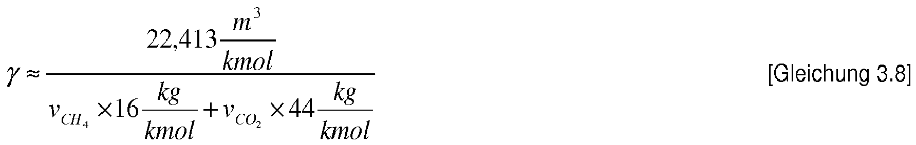
γ - represents the formation of biogas per mass of the organic, degradable dry matter, which can be calculated using Equation 4.8:
![]()
![]()
![]()
![]()
![]()
![]()
Die Berechnung der Konzentration von Ammonium-Stickstoff und Ammoniak erfordert eine genaue Bilanzierung aller Stickstofffraktionen sowie des Stickstoffkreislaufs. Selbst für sehr umfangreiche Modelle des anaeroben Abbaus wie z. B. ADM 1 [1 ist die Aufgabe, aufgrund der Komplexität der anaeroben Vorgänge, relativ schwierig. Im Rahmen der Arbeit wurde ein vereinfachtes Modell der Stickstoffbilanzierung implementiert und erprobt.The calculation of the concentration of ammonia-nitrogen and ammonia requires accurate calculation of all nitrogen fractions and the nitrogen cycle. Even for very extensive models of anaerobic degradation such. B. ADM 1 [1, the task is relatively difficult due to the complexity of the anaerobic processes. As part of the work, a simplified model of nitrogen balancing was implemented and tested.
Die Freisetzung des Ammonium-Stickstoffs wurde mit Hilfe der Annahme berechnet, dass Stickstoff homogen in der abbaubaren organischen Trockenmasse verteilt ist. Die Konzentration des Ammoniumstickstoffs im Reaktor ![]()

Konzentration an partikulären abbaubaren Stickstoff im zugeführten Substrat [kg/m3]
![]()
cN,abb - Konzentration an partikulären abbaubaren Stickstoff [kg/m3]
![]()
![]()
Concentration of particulate degradable nitrogen in the fed substrate [kg / m 3 ]
![]()
c N, abb - Concentration of particulate degradable nitrogen [kg / m 3 ]
![]()
In der hier vorgestellten Methode wurde angenommen, dass nahezu der gesamte Stickstoff in der organischen Trockensubstanz vorhanden ist. Da keine Untersuchungen über die Gesamtkinetik der Freisetzung von Ammonium vorlagen, wurde sie mit der der - Gesamtkinetik des anaeroben Abbaus ƒa(t) gleichgesetzt.In the method presented here it was assumed that almost all of the nitrogen is present in the organic dry matter. Since no studies on the overall kinetics of the release of ammonium were available, it was equated with that of the - total kinetics of anaerobic degradation ƒ a (t) .
Ein Teil des im Substrat enthaltenen Stickstoffs findet sich in der Bakterienbiomasse wieder. Mit Hilfe des Online-Bilanzierung-Modells (Kapitel 3.7) kann sowohl die durch Umwandlung von organischen N in NH4-N freigesetzte Stickstoffmenge, als auch die Menge, die von der Biomasse absorbiert wird, abgeschätzt werden. Der Stickstoffgehalt der Trockenmasse der anaeroben Bakterien kann zwischen 7% und 11 % betragen [3]. Für die vereinfachte Berechnung wurde angenommen, dass die Bakterienbiomasse etwa 9 % vom Stickstoff beinhaltet.Part of the nitrogen contained in the substrate is found in the bacterial biomass again. Using the online balancing model (chapter 3.7), both the amount of nitrogen released by conversion of organic N into NH 4 -N and the amount absorbed by the biomass can be estimated. The nitrogen content of the dry mass of the anaerobic bacteria can be between 7% and 11% [3]. For the simplified calculation, it was assumed that the bacterial biomass contains about 9% of the nitrogen.
Im Rahmen dieser Arbeit wurde mit Hilfe der hier dargestellten Abhängigkeiten ein Modell aufgestellt, anhand dessen eine Simulationssoftware erstellt worden ist. Damit konnte die dynamische Massenbilanzierung der Gärbehälter der untersuchten Biogasanlagen durchgeführt werden. Auf Grundlage des Modells wurden Entwürfe der Softsensoren entwickelt. Somit können unter anderem Online-Werte sowie die Vorhersage folgender Parameter der einzelnen Gärbehälter berechnet und abgeschätzt werden:
- maximal zu erwartende Biogasproduktion
- tatsächliche Biogas- und Methanausbeute der einzelnen Substrate
- TM des Faulschlammes sowie nicht abgebaute oTM-Menge (Biogaspotenzial des Faulschlammes),
- Konzentrationen von Ammoniak und Ammoniumstickstoff (in Verbindung mit Offline-Messwerten)
- maximum expected biogas production
- actual biogas and methane yield of the individual substrates
- TM of the digested sludge and undegraded oTM amount (biogas potential of the sludge),
- Concentrations of ammonia and ammonium nitrogen (in conjunction with offline measurements)
Darüber hinaus konnte anhand des Vergleiches der Simulationsergebnisse und der tatsächlichen Biogasproduktion der Verlauf der Konzentrationen an flüchtigen organischen Säuren abgeschätzt werden.Moreover, the comparison of the simulation results and the actual biogas production allowed to estimate the course of volatile organic acid concentrations.
Für die Steuerung und Regelung der Substratzufuhr ist die genaue Ermittlung der zu erwartenden Biogas- und Methanproduktion von Bedeutung. Mit Hilfe einer statischen Bilanzierung der Betriebsdaten lässt sich mit einer ausreichenden Genauigkeit für längere Zeiträume (z. B. 6 Monate) des Betriebes der Durchschnittswert berechnen. Diese Ergebnisse sind jedoch zur Steuerung und Regelung oder für ein Monitoring der Anlagen nicht zu verwenden. Laut der Ergebnisse der Analyse der Betriebsdaten ist es daher zwingend notwendig, die zu erwartenden Methan- und Biogasproduktionen über dynamische Simulation zu berechnen.For the control and regulation of the substrate supply, the exact determination of the expected biogas and methane production is of importance. With the aid of a static balancing of the operating data, the average value can be calculated with sufficient accuracy for longer periods (
Das Modell, das im Kapitel 3.5 vorgestellt wurde, wurde unter anderem für die dynamische Berechnung der Soll-Biogasproduktion sowie der Soll-Methanproduktion für die Biogasanlagen 1 und 3 genutzt. Die Online-Berechnung wurde unter folgenden Annahmen durchgeführt:
- ● Die Biogasausbeute der Substrate ist konstant im gesamten Zeitraum
- ● Die anaeroben Reaktoren (Fermenter und Nachgärer) sind ideal durchmischt
- ● Ein bestimmter Anteil des Nutzvolumens des Reaktors ist durchgängig vom Biogas belegt
- ● The biogas yield of the substrates is constant throughout the period
- ● The anaerobic reactors (fermenter and post-fermenter) are ideally mixed
- ● A certain proportion of the useful volume of the reactor is continuously occupied by biogas
Die Ergebnisse der gemessenen und berechneten Biogasproduktion für die Biogasanlage 1 können
In den ersten Monaten des Betriebes wurde die Biogasmenge rechnerisch höher als die gemessene Biogasproduktion eingeschätzt. Das kann folgende Ursachen haben:
- ● Die Bakterienpopulation hat sich noch nicht entwickelt, wodurch die Substrate nicht vollständig in Biogas umgewandelt wurden (Inbetriebnahmephase)
- ● In den Gärbehältern lagen erhöhte Konzentrationen an organischen Säuren vor, wodurch eine erhebliche Fracht aus Säuren mit den Gärresten in den Gärrestspeicher gelangte
- ● The bacterial population has not yet developed, as a result of which the substrates have not been completely converted into biogas (commissioning phase)
- ● Increased concentrations of organic acids were present in the fermentation tanks, resulting in a significant load of acids with digestate in the digestate storage
Ab Tag 180 zeigen die Ergebnisse der berechneten Biogasproduktion eine Übereinstimmung mit der gemessenen Biogasproduktion. Es ist deutlich zu erkennen, dass die Dynamik der Prozesse gut abgebildet wurde.From day 180, the results of the calculated biogas production show a correspondence with the measured biogas production. It can be clearly seen that the dynamics of the processes were well represented.
Das Beispiel zeigt, dass eine relativ einfache Modellierung der anaeroben Biogasprozesse und eine einfache Technik zur Charakterisierung des Anlageninputs (offline TM Messung), eine hinreichende Genauigkeit liefern kann.The example shows that a relatively simple modeling of the anaerobic biogas processes and a simple technique for characterizing the system input (offline TM measurement) can provide sufficient accuracy.
Es ist deutlich zu erkennen, dass die berechnete Methan- und Biogasproduktion nicht eng mit den tatsächlichen Werten übereinstimmen. Dafür gibt es folgende Gründe. Zum einen wurden die TM- und oTM-Messungen für wenige Substrate und nur für Stichproben (im Zeitraum der mit Nr. 1 markiert wurde) ausgeführt. Zum anderen wurden für die Berechnung Annahmen zur Abbaukinetik getroffen, da die Untersuchungen dazu nicht durchgeführt wurden.It can be clearly seen that the calculated methane and biogas production do not closely match the actual values. There are the following reasons. On the one hand, the TM and oTM measurements were carried out for a few substrates and only for random samples (in the period marked # 1). On the other hand assumptions for the reduction kinetics were made for the calculation, since the investigations were not carried out for this purpose.
Die Ergebnisse der Simulation für die BGA 3 können
Im Laufe des weiteren Betriebes sind die tatsächlichen Ammonium-Stickstoff-Konzentrationen angestiegen (
Die Ergebnisse zeigen, dass die FOS-Konzentration im Gärbehälter mit Hilfe der Offline-Messungen sowie der Online-Massenbilanzierung kontrolliert werden kann. Mit Hilfe des entwickelten Modells kann vorausschauend berechnet werden wie sich die Konzentrationen an organischen Säuren aktuell entwickelt. Damit können jedoch keine langfristigen Vorhersagen erstellt werden.The results show that the FOS concentration in the fermentation tank can be controlled by offline measurements and online mass balancing. With the aid of the developed model, it is possible to calculate in advance how the concentrations of organic acids are currently being developed. However, this can not be used to create long-term forecasts.
Die Ergebnisse der TM Berechnung mit Hilfe des Softsensors und TM-Messwerten für die Biogasanlage 1 sind in
Die
Die anlagenweite Steuerung und Regelung der Biogasanlagen kann in drei miteinander gekoppelte Teilbereiche unterteilt werden:
- ● Messen, Steuern und Regeln der Produktionskapazitäten (z. B. der Gasverwertung, der Energieproduktion der Biogasanlage, der Speicherkapazität des Gärrestes)
- ● Messen, Steuern und Regeln der anaeroben Abbauvorgänge (z. B. die Regelung der Substratzufuhr hinsichtlich der Stabilität des Prozesses oder maximaler Ausnutzung der Substrate)
- ● Messen und Überwachen von Maschinen und Anlagenteilen (z B. des BHKW, der Rührwerkstechnik, der Pumptechnik)
- ● Measuring, controlling and regulating production capacities (eg gas utilization, energy production of biogas plant, storage capacity of digestate)
- ● measuring, controlling and regulating the anaerobic degradation processes (eg controlling the substrate supply with regard to the stability of the process or maximum utilization of the substrates)
- ● Measuring and monitoring of machines and system parts (eg of CHP, stirrer technology, pump technology)
Das MSR der Produktionskapazitäten beinhaltet alle Kontrollmechanismen zur Messung der vorhandenen Anlagenkapazitäten, wie Energieproduktion, Durchsatzleistung sowie Biogasproduktion, und definiert die übergeordneten Ziele für die Anlage zur Auslastung der vorhandenen Kapazitäten. Da die Entscheidungen die Wirtschaftlichkeit der Anlage direkt beeinflussen, werden sie oft direkt vom Betreiber getroffen. Im Rahmen der Arbeit wird ein voll automatisiertes MSR-Konzept zur Steuerung und Regelung der Biogasverwertungsanlagen (z. B. BHKW) sowie ein MSR-Konzept zur wirtschaftlich optimalen Substratzufuhr des Gärbehälters entwickelt und dargestellt.The MSR of production capacity includes all control mechanisms for measuring existing plant capacities, such as energy production, throughput and biogas production, and defines the overriding objectives for the facility to utilize existing capacity. Since the decisions directly affect the profitability of the system, they are often directly taken by the operator. Within the scope of the work, a fully automated MSR concept for the control and regulation of the biogas utilization plants (eg CHP) as well as an MSR concept for the economically optimal substrate supply of the fermentation tank will be developed and presented.
Die MSR-Technik der anaeroben Abbauvorgänge beschäftigt sich überwiegend mit der Kontrolle sowie der Steuerung und Regelung der Gärbehälter. Darunter versteht man die entsprechende Prozessführung der Fermentation. Durch die Prozessführung werden Produktionsziele erreicht und ein stabiler Betrieb gewährleistet. Die Überwachung und Kontrolle der Stabilität der Fermentation spielt eine sehr wichtige Rolle, weil sie direkt mit der Wirtschaftlichkeit durch optimale Gasproduktion und Ausnutzung der Methanausbeuten steht. Im Rahmen der Arbeit wird ein MSR-Konzept für die Fermentation vorgeschlagen.The MSR technology of anaerobic mining operations is mainly concerned with the control and the control and regulation of the fermentation tank. This refers to the corresponding process control of the fermentation. Process management achieves production goals and ensures stable operation. The monitoring and control of the stability of the fermentation plays a very important role, because it stands directly with the economy by optimal gas production and utilization of the Methanausbeuten stands. The work proposes an MSR concept for fermentation.
Die erreichbare Auslastung der Biogasanlage und die mittlere Energieproduktion hängen sehr stark vom zuverlässigen Betrieb der Anlagenteile und der Maschinen ab. Ein Ausfall des BHKW oder des Rührwerks kann schwerwiegende wirtschaftliche Folgen haben. Daher müssen die wichtigen Anlagenteile messtechnisch überwacht werden, damit deren Ausfallrisiko minimiert wird. Dies wird jedoch in der Praxis oftmals nicht umgesetzt. Zudem finden sich in der Fachliteratur nur wenige Informationen dazu.The achievable utilization of the biogas plant and the average energy production depend very much on the reliable operation of the plant components and the machines. Failure of the CHP or agitator can have serious economic consequences. For this reason, the important plant components must be metrologically monitored so that their risk of failure is minimized. However, this is often not implemented in practice. In addition, only a small amount of information can be found in the specialist literature.
Die verfahrenstechnische Ausführung der Biogasanlage wie z. B. die Anzahl der Fermentationsstufen, das aktive Nutzvolumen des Gärraums und der Temperaturbereich der Fermentation (mesophil oder thermophil) haben einen sehr großen Einfluss auf die Möglichkeiten der Steuerung und Regelung der Biogasanlage.The procedural execution of the biogas plant such. As the number of fermentation stages, the active effective volume of the fermentation chamber and the temperature range of the fermentation (mesophilic or thermophilic) have a very large impact on the possibilities of controlling and regulating the biogas plant.
Das Inputmanagement sollte auf Biogasanlagen eine zentrale Rolle spielen, da Informationen wie die Substratverfügbarkeit, die Substratkosten oder die Ergebnisse der Substratrecherche (Untersuchungsergebnisse der Biogasausbeute von neuen potenziellen Substraten) sowohl auf die Zufuhrstrategie des Betriebes als auch auf dessen Steuerung und Regelung einen sehr großen Einfluss haben.Input management should play a key role in biogas plants, as information such as substrate availability, substrate costs or substrate research results (biogas yield from new potential substrates) has a major impact on both the supply strategy of the plant and its control and regulation ,
Das Informationsmanagement spielt auf Biogasanlagen eine immer wichtigere Rolle. Die Informationen müssen gesammelt, ausgewertet und an die Betreiber weitergegeben werden. Für eine effiziente Nutzung, der auf der Anlage gesammelten Informationen, muss ein Datenmanagement geschaffen werden, mit dem Informationen geprüft, gesammelt und verwaltet werden können. Ähnlich wie bei Kläranlagen werden automatisierte Betriebstagebücher, Substratannahme- und Gärrestabgabestationen entwickelt, die mit dem Prozessleitsystem verbunden sind. Die Steuerung und Regelung von Anlagen ist noch weit davon entfernt voll automatisiert zu erfolgen. Deswegen werden in naher Zukunft verstärkt halb automatische Systeme erforderlich sein, die durch Visualisierung der Daten oder über andere Kommunikationswege (z. B. über das Telefon, Alarm- und Lichthupe) dem Betreiber Informationen übermitteln. Die Art und Weise der Informationsübermittlung spielt für Betreiber von Biogasanlagen eine zentrale Rolle (sie muss oft an projektspezifische Gegebenheiten angepasst werden), da diese Elemente zur Steigerung des Prozessverständnisses führen und die Entscheidung über Betriebsablaufe vereinfachen. Dieser Themenbereich wurde jedoch im Rahmen dieser Arbeit nicht näher betrachtet.Information management is playing an increasingly important role on biogas plants. The information must be collected, evaluated and passed on to the operators. For efficient use of the information collected on the site, data management must be provided to verify, collect and manage information. Similar to wastewater treatment plants, automated daily operating logs, substrate receiving and digestate dispensing stations are being developed that are connected to the process control system. The control and regulation of plants is still far from being fully automated. Therefore, in the near future, more and more semi-automatic systems will be required, which transmit information to the operator by visualizing the data or by other means of communication (eg via telephone, alarm and flashlight). The way in which information is transmitted plays a key role for operators of biogas plants (it often has to be adapted to project-specific circumstances), since these elements increase the understanding of the process and simplify the decision on operating procedures. However, this topic was not considered in the context of this work.
Die Untersuchungen zum Einsatz der Messtechnik sowie die statische und die dynamische Bilanzierung der Anlagen bilden die Grundlage für die Entwicklung eines anlagenweiten Konzeptes. Anhand der gesammelten Informationen sowie den entwickelten Werkzeugen wurde ein Entwurf des anlagenweiten Steuerungs- und Regelungssystems erstellt, der im Folgenden vorgestellt wird.The investigations into the use of measuring technology as well as the static and dynamic balancing of the plants form the basis for the development of a plant-wide concept. Based on the information gathered and the tools developed, a design of the plant-wide control system was developed, which is presented below.
Um die Biogasanlagen überwachen, steuern und regeln zu können, muss die messtechnische Ausrüstung viele Aufgaben gleichzeitig erfüllen:
- ● Erhebung von Informationen über Zustand und Kapazität des Prozesses des anaeroben Abbaus und Biogasproduktion
- ● Erhebung von Informationen über Zustand von Maschinen und Aggregaten der Biogasanlage (z. B. Pumpen, BHKW, Rührwerke, Feststoffeintrag)
- ● Erhebung von Informationen über Nutzung von vorhandenen Kapazitäten (z. B. Füllstände von Gas und Flüssigkeit in Gärbehältern, Füllstand im Gärrestbehälter)
- ● Erhebung von Informationen über sicherheitstechnische Aspekte des Betriebes (z. B. Konzentrationen von gefährlichen Gasen wie CH4 und H2S, Schutz vor Überfüllung des Behälters)
- ● To collect information on the condition and capacity of the process of anaerobic digestion and biogas production
- ● Collection of information on the condition of machines and units of the biogas plant (eg pumps, CHP units, agitators, solids entry)
- ● Collection of information on the use of existing capacities (eg fill levels of gas and liquid in fermentation tanks, level in the digestate tank)
- ● Collection of information on safety aspects of the operation (eg concentrations of dangerous gases such as CH 4 and H 2 S, protection against overfilling of the container)
Der erforderliche Umfang der messtechnischen Ausrüstung bzw. des Messsystems und Messprogramms bei einer konkreten Anlage hängt von den spezifischen Randbedingungen und der Aufgabestellung ab. Bei der Wahl der Messtechnik spielen verschiedene Faktoren eine wichtige Rolle, da messtechnische Einrichtungen unterschiedliche Eigenschaften aufweisen (z. B.: Häufigkeit der Messung, Genauigkeit, Repräsentativität der Probe, Aufwand für die Kalibrierung, Art der Probenaufbereitung, Kosten der Messeinrichtung und der Messung).The required scope of the metrological equipment or the measuring system and measuring program for a specific plant depends on the specific boundary conditions and the task. Various factors play an important role in the choice of measurement technology, since metrological devices have different properties (eg: frequency of measurement, accuracy, representativeness of the sample, costs for the calibration, type of sample preparation, costs of the measuring device and the measurement) ,
Der Zustand und die Produktivität der Fermenterbiologie hängen von den eingesetzten Substraten, der verfahrenstechnischen Auslegung der Anlage und der Stabilität der Prozesse ab. Die Stabilität der anaeroben Prozesse ist abhängig von:
- ● Größe und Art (z. B. kontinuierliche oder diskontinuierliche, regelmäßige oder unregelmäßige) der Belastung des Fermenters
- ● Eigenschaften der eingesetzten Substrate:
- o Zusammensetzung (Gehalt an Proteinen, Fette, Kohlenhydrate) sowie Dynamik des Substratabbaus
- o Gehalt der potenziellen Hemm- und/oder Giftstoffe
- o Gehalt der Spurenelemente
- o Eignung zur Bildung der Hemm- und Giftstoffe (z. B. Schwefelwasserstoff, Ammoniak, organischen Säuren) im Laufe des anaeroben Abbaus
- o Eignung zur Bildung von Ausgangssubstraten der Verbindungen, die für Erhöhung der Pufferkapazität sorgen
- ● Size and type (eg continuous or discontinuous, regular or irregular) of the load on the fermenter
- ● Properties of the substrates used:
- o Composition (content of proteins, fats, carbohydrates) and dynamics of substrate degradation
- o Content of potential inhibitors and / or toxins
- o content of trace elements
- o Suitability for the formation of inhibitors and toxins (eg hydrogen sulphide, ammonia, organic acids) in the course of anaerobic digestion
- o Suitability to form starting substrates of compounds that provide increase in buffering capacity
In dieser Arbeit wurde besonderes Augenmerk auf die Erhebung und die Aufbereitung der plausiblen Messdaten für das Steuern und Regeln der Biogasanlage gelegt. Ein zuverlässiges Messsystem ist die Grundlage für das Monitoring sowie für die Steuerung und Regelung der Biogasanlage.In this work, special attention was paid to the collection and processing of the plausible measurement data for controlling and regulating the biogas plant. A reliable measuring system is the basis for the monitoring as well as for the control and regulation of the biogas plant.
Die Schlussfolgerung der umfangreichen Analyse der Messetechnik für Biogasanlagen ist, dass derzeit auf dem Markt keine zuverlässige Messtechnik erhältlich ist, welche die Schlüsselparameter (Konzentration der organischen Säuren, Konzentration des Ammoniumstickstoffes und Säurekapazität) online bestimmen kann, sodass die für Steuerungs- und Regelungsstrategien erforderlichen Werte anderweitig gewonnen werden müssen. Über eine Kombination von Offline- und Online-Messtechnik können relativ viele zuverlässige Informationen gesammelt werden, die für ein einfaches Monitoring ausreichen. Für die Steuerung und Regelung muss jedoch die Qualität und die Zuverlässigkeit der Daten verbessert werden.The conclusion of the extensive analysis of biogas plant measurement technology is that there is currently no reliable measurement technology available on the market that can determine the key parameters (organic acid concentration, ammonium nitrogen concentration and acid capacity) online, thus requiring the control and regulatory strategies required have to be won elsewhere. A combination of offline and online measurement technology can provide a relatively large amount of reliable information that is sufficient for easy monitoring. However, for control and regulation, the quality and reliability of the data must be improved.
Im Rahmen der Arbeit wurden Softsensoren für Biogasanlagen entwickelt und in ein Simulationen erprobt. Die Sensoren basieren im Wesentlichen auf einem Online-Massenbilanzierungsmodell, welches in Rahmen der Arbeit entwickelt wurde.Within the scope of this work, soft sensors for biogas plants were developed and tested in simulations. The sensors are essentially based on an online mass balancing model, which was developed as part of the work.
Die organischen Säuren (FOS - flüchtige organische Säuren), die TM-Konzentration im Faulschlamm, sowie die NH4-N Konzentration können mit Hilfe der Softsensoren, die auf dem Modell basieren, ermittelt werden. Dadurch kann der Verlauf der Messwerte zwischen den Laboranalysemesswerten ermittelt und zum Zweck der Steuerung und Regelung genutzt werden. Die Häufigkeit der Offline-Messungen wird anhand der Trendentwicklung sowie anderer Online-Kontrollparameter (pH, Redox Leitfähigkeit) festgelegt.The organic acids (FOS - volatile organic acids), the TM concentration in the digested sludge and the NH 4 -N concentration can be determined with the help of the model based soft sensors. As a result, the course of the measured values between the laboratory analysis measured values can be determined and used for the purpose of control and regulation. The frequency of offline measurements is determined by trend development and other online control parameters (pH, redox conductivity).
Die Prozesskontrolle beruht auf der Auswertung des Unterschiedes der gemessenen Methan/Biogas-Produktion und der berechneten Methan/Biogas-Produktion. Weichen die beiden Werte zu stark voneinander ab, kann dies zwei Ursachen haben:
- ● Abweichung durch Entweichung des Biogases durch Undichtigkeiten im System
- ● Anaeroben Abbauprozesse verlaufen instabil.
- ● Deviation due to leakage of the biogas due to leaks in the system
- ● Anaerobic degradation processes are unstable.
Ein weiterer Einsatz des entwickelten Modells ist für die Analyse der Betriebsdaten der Anlage möglich. Durch Einsatz in der Simulation einer einfachen iterativen Näherung oder eines Optimierungsalgorithmuses (z. B. genetischer Algorithmus oder Simplexverfahren) können folgende Parameter ermittelt werden:
- ● maximale Biogas- und Methanausbeute für jedes eingesetzte Substrat
- ● auf der Anlage erreichte Biogas- und Methanausbeute für jedes eingesetzte Substrat
- ● Restgaspotenzial der Gärreste
- ● maximum biogas and methane yield for each substrate used
- ● The plant achieved biogas and methane yield for each substrate used
- ● Residual gas potential of digestate
Auf diese Art und Weise können sehr wichtige Informationen für den Betrieb der Anlage gewonnen werden.In this way very important information for the operation of the plant can be obtained.
Die Berechnung des TAC-Wertes war anhand der Bilanzierung nicht möglich, daher wird der Wert mit Hilfe einer Offline-Messung ermittelt. Im Rahmen der Untersuchung wurde jedoch beobachtet, dass der Parameter mit der Leitfähigkeit des Faulschlammes gut korreliert. Zudem ist die Bestimmung der Pufferkapazität mit Hilfe von BiogasPro eine robuste und einfache Methode. Die Automatisierung der Messung könnte einen großen Vorteil der MSR-Technik für Biogasanlagen bringen.The calculation of the TAC value was not possible on the basis of the balancing, therefore the value is determined by means of an offline measurement. During the investigation, however, it was observed that the parameter correlated well with the conductivity of the digested sludge. In addition, the determination of buffer capacity using BiogasPro is a robust and simple method. The automation of the measurement could bring a great advantage of the MSR technology for biogas plants.
Die Online-Messungen von Kontrollgrößen wie pH, das Redox-Potenzial und die Leitfähigkeit sind zwar sehr robust und geeignet für den Einsatz auf Biogasanlagen, liefern jedoch Informationen, die für die Steuerung und die Regelung der Biogasanlagen nur begrenzt zu verwerten sind. Der pH-Wert ist abhängig von vielen unterschiedlichen Parametern wie beispielsweise Alkalinität und Säurekonzentration. Eine signifikante Verminderung des Parameters bedeutet, dass die biologische Stufe sich bereits in einem extrem instabilen Zustand befindet. In der Regel ist es dann zu spät, um reagieren zu können und um erhebliche Leistungseinschränkung zu verhindern. Die Parameter können jedoch in der sogenannten Notbremse- und Alarmfunktion eine entscheidende Rolle spielen. Die sensibleren Parameter wie Säurekonzentration (insbesondere Propionsäurekonzentration) und Wasserstoffkonzentration in der gelösten Phase informieren wesentlich schneller über Probleme im Prozessablauf.Although the online measurements of control parameters such as pH, the redox potential and the conductivity are very robust and suitable for use in biogas plants, they provide information that can only be used to a limited extent for the control and regulation of biogas plants. The pH depends on many different parameters such as alkalinity and acid concentration. A significant reduction in the parameter means that the biological step is already in an extremely unstable state. In general, it is then too late to react and to prevent significant performance restriction. However, the parameters may be in the so-called emergency brake and alarm function play a crucial role. The more sensitive parameters such as acid concentration (in particular propionic acid concentration) and hydrogen concentration in the dissolved phase provide much faster information about problems in the process flow.
- 1. Dynamische Bilanzierung der Massenströme. Mit Hilfe des entwickelten Modells werden die maximale Methan- und Biogasausbeute sowie die maximale Abbaurate der einzelnen Substrate berechnet. Die Berechnung wird anhand der Simulation der letzten Wochen des Betriebes erstellt.
- 2. Optimierung der Substratzufuhrstrategie. Anhand der zur Verfügung stehenden Substratmischung der einzelnen Substraten, deren Methanausbeuten und der Abbaurate sowie der Zusammensetzung (TM, oTM, TS, oTS, Gesamtstickstoff und NH4-N), werden verschiedene zukünftige Substratzufuhrszenarien mit Hilfe des entwickelten Modells simuliert. Dabei wird das Szenario gewählt bei der die angestrebte Methanausbeute (Energieausbeute) bei maximalen Abbaurate der organischen Trockenmasse der Substrate erzielt wird. Gleichzeitig werden folgende Bedingungen erfüllt:
- a. NH4-N-Konzentrationen im Fermenter und Nachgärer sind kleiner als der vorgegebene Sollwert
- b. TM-Konzentration im Fermenter und Nachgärer sind kleiner als der vorgegebene Sollwert.
ein Regelungssystem 3 im laufenden Betrieb der Biogasanlage geregelt wird, dem als Eingangsgröße eine durch Computersimulation bestimmte Substratzufuhr-Strategie zugeführt wird, die nach Maßgabe der verfügbaren Substrate bestimmt ist.
Auf dem Computer kann z. B. die dynamische Bilanzierung der Massenströme gemäß dem in Kapitel 4.6 beschriebenen Modell ausgeführt werden. Die Bestimmung der Substratzufuhr-Strategie kann z.B. anhand der Simulation der letzten Wochen des Betriebes der Biogasanlage durchgeführt werden.
Gemäß einer vorteilhaften Ausführungsform der Erfindung werden anhand der Vorratsmengen und Arten der verfügbaren Substrate sowie deren charakteristischer Methanausbeutewerte und ihrer Abbaurate verschiedene zukünftige Substratzufuhrstrategien zunächst mittels eines Computers simuliert, die Substratzufuhrstrategie mit einer angestrebten Methanausbeute bzw. Energieausbeute bei einer maximalen Abbaurate der organischen Trockenmassen ausgewählt und sodann die Regelung der Biogasanlage gemäß der ausgewählten Substratzufuhrstrategie durchgeführt.
Gemäß einer vorteilhaften Ausführungsform der Erfindung wird aus den simulierten Substratzufuhrstrategien diejenige ausgewählt, bei der die NH4-N Konzentrationen im Fermenter und im Nachgärer der Biogasanlage jeweils kleiner als ein vorgegebener Sollwert sind.
Gemäß einer vorteilhaften Ausführungsform der Erfindung wird diejenige Substratzufuhrstrategie ausgewählt, bei der die Trockenmasse Konzentration im Fermenter und im Nachgärer jeweils kleiner ist als ein vorgegebener Sollwert. Gemäß einer vorteilhaften Ausführungsform der Erfindung wird ein Verfahren zur Regelung einer Biogasanlage vorgeschlagen, bei dem im laufenden Betrieb der Biogasanlage eine oder mehrere der Größen: Methanausbeute, Biogasausbeute und Abbaurate der der Biogasanlage zugeführten einzelnen Substrate, unter Heranziehung im laufenden Betrieb gemessener Zulauf- und Ablaufströme des Fermenters und/oder des Nachgärers der Biogasanlage nach Art einer Massenbilanz bestimmt werden und als Eingangsgröße für die Computersimulation zur Bestimmung der Substratzufuhrstrategie verwendet werden.
Durch die zuvor erläuterten Ausführungsformen wird der Regelungssystem 3 mit einer optimiertenSubstratzufuhrstrategie als Eingangsgröße 4 versorgt, wie inAbbildung 0.13 dargestellt. Die Erfindung betrifft ferner die Optimierung der Regelung der weiteren Parameter des Regelkreises, insbesondere der Reglereingangsgröße 7 und der Stellgröße 8 desRegelungssystems 3. Diese Optimierungen können kombiniert mit oder auch unabhängig von den zuvor erläuterten Ausführungsformen realisiert werden. - 3. Regelungssystem. Das System erstellt eine optimale Substratzufuhrstrategie separat für Fermenter und Nachgärer.
- a. Stellgrößen: Menge der Substratmischung pro Fermenter und Nachgärer
- b. Führungsgrößen: maximale Konzentration von flüchtigen organischen Säuren, maximale FOS/TAC-Verhältnis, maximale Tendenz der Bildung von flüchtigen organischen Säuren, maximale Tendenz der Bildung des FOS/TAC-Verhältnisses, vorgegebene Methanproduktion
- c. Regelgrößen: Konzentration von flüchtigen organischen Säuren, FOS/TAC-Verhältnis, Tendenz der Bildung der flüchtigen organischen Säuren, Tendenz der Bildung des FOS/TAC- Verhältnisses, aktuelle Methanproduktion
- 1. Dynamic balancing of mass flows. With the help of the developed model the maximum methane and biogas yield as well as the maximum degradation rate of the individual substrates are calculated. The calculation is based on the simulation of the last weeks of operation.
- 2. Optimization of the substrate delivery strategy. On the basis of the available substrate mixture of the individual substrates, their methane yields and the degradation rate and the composition (TM, oTM, TS, oTS, total nitrogen and NH 4 -N), various future substrate delivery scenarios are simulated using the developed model. Here, the scenario is chosen in which the desired methane yield (energy yield) is achieved with maximum degradation rate of the organic dry matter of the substrates. At the same time the following conditions are met:
- a. NH 4 -N concentrations in the fermenter and post-fermenter are lower than the specified setpoint
- b. TM concentration in the fermenter and post-fermenter are smaller than the specified setpoint.
control system 3 during operation of the biogas plant, as the input a determined by computer simulation substrate supply Strategy, which is determined according to the available substrates.
On the computer can z. B. the dynamic balancing of the mass flows are carried out according to the model described in chapter 4.6. The determination of the substrate supply strategy can be carried out, for example, based on the simulation of the last weeks of operation of the biogas plant.
According to an advantageous embodiment of the invention, based on the stocks and types of available substrates and their characteristic Methanausbeutewerte and their degradation rate various future Substratatzuhrstrategien first simulated by a computer, the Substratatzufuhrstrategie with a targeted methane yield or energy yield at a maximum degradation rate of the organic dry mass selected and then the regulation of the biogas plant according to the selected substrate supply strategy performed.
According to an advantageous embodiment of the invention, the one selected from the simulated substrate supply strategies in which the NH 4 -N concentrations in the fermenter and in the post-fermenter of the biogas plant are each smaller than a predetermined desired value.
According to an advantageous embodiment of the invention, that substrate supply strategy is selected in which the dry matter concentration in the fermenter and in the post-fermenter is in each case smaller than a predetermined desired value. According to an advantageous embodiment of the invention, a method for controlling a biogas plant is proposed, in which during operation of the biogas plant one or more of the variables: methane yield, biogas yield and degradation rate of the biogas plant supplied individual substrates, using in-line operation measured inflow and outflow streams the fermenter and / or the post-fermenter of the biogas plant are determined in the manner of a mass balance and used as an input for the computer simulation to determine the substrate supply strategy.
As a result of the embodiments explained above, thecontrol system 3 is supplied with an optimized substrate delivery strategy as aninput variable 4, as in FIGFigure 0.13 shown. The invention further relates to the optimization of the control of the further parameters of the control loop, in particular thecontroller input variable 7 and the manipulatedvariable 8 of thecontrol system 3. These optimizations can be realized combined with or independently of the previously described embodiments. - 3rd regulatory system. The system creates an optimal substrate delivery strategy separately for fermenter and post-fermenter.
- a. Manipulated variables: amount of substrate mixture per fermenter and post-fermenter
- b. Guide variables: maximum concentration of volatile organic acids, maximum FOS / TAC ratio, maximum tendency of formation of volatile organic acids, maximum tendency of formation of FOS / TAC ratio, given methane production
- c. Controlled variables: Concentration of volatile organic acids, FOS / TAC ratio, tendency of the formation of the volatile organic acids, tendency of the formation of the FOS / TAC-ratio, current methane production
Gemäß einer vorteilhaften Ausführungsform der Erfindung stellt das Regelungssystem als Stellgröße die Menge der Substratmischung jeweils separat für den Fermenter und für den Nachgärer ein.According to an advantageous embodiment of the invention, the control system as the manipulated variable, the amount of the substrate mixture in each case separately for the fermenter and for the post-fermenter.
Somit erhält das Regelungssystem der Anlage wichtige Informationen, die notwendig sind um die Substratzufuhr der Biogasanlage sowie die Massenströme optimal zu regeln. Der Regelkreis wird geschlossen, indem die Informationen direkt (über Sonden und Labormesswerte) und/oder indirekt (über Softsensoren) von den anaeroben Reaktoren und deren Ablauf- und Zulaufströmen erhoben werden. Bei der gesamten Regelung werden folgende Vorteile erreicht:
- ● Stabiler Betrieb: Langfristige Sicherung des TM-Gehaltes (Pumpfähigkeit des Substrates) und der NH4-N Konzentration im Fermenter und Nachgärer unter vorgegebenen Grenzwerten; kurzfristige Sicherung des Gehaltes an flüchtigen organischen Säuren, FOS/TAC unter vorgegebenen Grenzwerten
- ● Gute Wirtschaftlichkeit im Betrieb: Optimale Ausnutzung der Methan- und Biogasbildungspotenziale der eingesetzten Substrate sowie stabile Methanproduktion auf einem hohen angestrebten Level
- ● Feedback vom System: Über die Bilanzierung der Massenströme und des Stickstoffes werden die tatsächlichen Methan- und Biogasausbeuten sowie maximale und tatsächliche Abbauraten der eingesetzten Substrate ermittelt. Die Informationen werden primär zur Erstellung der Zufuhrstrategie genutzt, können aber auch für die Planung des Betriebes genutzt werden
- ● Stable operation: Long-term protection of the TM content (pumpability of the substrate) and the NH 4 -N concentration in the fermenter and post-fermenter below specified limits; short-term protection of the volatile organic acid content, FOS / TAC below specified limits
- ● Good economic efficiency in operation: optimum utilization of the methane and biogas formation potentials of the substrates used as well as stable methane production at a high desired level
- ● Feedback from the system: By balancing the mass flows and the nitrogen, the actual methane and biogas yields as well as the maximum and actual degradation rates of the substrates used determined. The information is primarily used to create the supply strategy, but can also be used to plan the operation
In mehreren Forschungsvorhaben wurden die Parameter und deren Grenzwerte, deren Einhaltung für die Stabilität des Gärprozesses und damit für die Maximierung der Biogasproduktion notwendig ist, ermittelt und festgelegt. Diese Literaturwerte können als Grundlage für den Betrieb des Steuerungssystems genutzt werden.In several research projects, the parameters and their limit values, the compliance of which is necessary for the stability of the fermentation process and thus for the maximization of the biogas production, were determined and determined. These literature values can be used as a basis for the operation of the control system.
Es ist bekannt, dass die anaerobe Biozönose sich an unterschiedliche Bedingungen anpassen kann. Aufgrund der Adaption der Biozönose müssen die tolerierbaren Grenzen der Stabilitätsparameter ständig untersucht und angepasst werden. Der Betreiber hat beim Einsatz der Regelung die Möglichkeit die Sollwerte ständig anzupassen. Da für die Regelung ständig die tatsächliche, aktuelle Abbaurate der Substrate sowie die tatsächlichen, aktuellen Biogas- und Methanausbeuten der einzelnen Substrate ermittelt werden, passt sich die Regelung an die Betriebsbedingungen an. Somit besitzt das entwickelte System eine Lernfunktion.It is known that the anaerobic biocenosis can adapt to different conditions. Due to the adaptation of the biocenosis, the tolerable limits of the stability parameters must be constantly investigated and adapted. When using the control, the operator has the option of constantly adjusting the setpoints. Since the control system constantly determines the actual, current degradation rate of the substrates as well as the actual, current biogas and methane yields of the individual substrates, the control adapts to the operating conditions. Thus, the developed system has a learning function.
Die Beibehaltung der Fließfähigkeit des Faulschlammes ist ein wichtiges Thema in Bezug auf den störungsfreien Betrieb der Anlagen. Der Faulschlamm sowie die frischen Substrate werden mit Hilfe der Pumptechnik von Behälter zu Behälter umgepumpt. Je nach Pumptechnik und den hydraulischen Eigenschaften der Rohrleitungen (hydraulischer Widerstand) kann das Fördern des Substrates bei einer hohen Viskosität des Mediums erschwert werden. Je höher der TM-Gehalt des Faulschlammes desto höher ist auch dessen Viskosität. Die TM-Grenze für eine bestimmte Biogasanlage kann für die Regelung individuell eingestellt werden. Für die im Rahmen dieser Arbeit untersuchten Biogasanlagen lag die Grenze bei ca. 9% TM. Die Regelung kann eine optimale Kombination der Substrate bestimmen (Funktion der Prädikation des TM Gehaltes sowie des NH4-N Gehaltes), sodass die Fließfähigkeitsgrenze in den Gärbehältern nicht überschritten wird.Maintaining the flowability of the digested sludge is an important issue in terms of the trouble-free operation of the plants. The digested sludge and the fresh substrates are pumped from tank to tank using the pumping technique. Depending on the pumping technique and the hydraulic properties of the pipelines (hydraulic resistance), it may be difficult to convey the substrate if the viscosity of the medium is high. The higher the TM content of the digested sludge the higher is its viscosity. The TM limit for a specific biogas plant can be set individually for the regulation. For the biogas plants investigated in this work, the limit was about 9% TM. The control can determine an optimal combination of substrates (function of the prediction of the TM content and the NH 4 -N content) so that the flow limit in the fermentation tanks is not exceeded.
Eine optimale Substratzufuhrstrategie muss den wirtschaftlichen Betrieb der Anlage garantieren. Daher muss die Regelung sowohl die Substratpreise als auch deren tatsächliche Biogasausbeute berücksichtigen.An optimal substrate feeding strategy must guarantee the economic operation of the plant. Therefore, the scheme must take into account both substrate prices and their actual biogas yield.
Der Algorithmus des Regelungssystems wird in
Im Folgenden werden die einzelne Bedingungen "B", Regler "R" und Schritte "S" erklärt:
- B1: Die Bedingung ist erst dann erfüllt, wenn die Konzentration der flüchtigen organischen Säuren, das FOS/TAC-Verhältnis, die Tendenz der Bildung der organischen Säuren und die Tendenz der Bildung der FOS/TAC Verhältnisses im Fermenter kleiner als die jeweiligen Grenzwerte sind.
- B2: Die Bedingung ist erst dann erfüllt, wenn die aktuelle Methanproduktion höher als der angestrebte Wert für die Biogasanlage liegt und kein frisches Substrat in den Nachgärer gegeben wird.
- B3: Die Bedingung ist erst dann erfüllt, wenn die Konzentration der flüchtigen organischen Säuren, das FOS/TAC-Verhältnis, die Tendenz der Bildung der organischen Säuren und die Tendenz der Bildung der FOS/TAC-Verhältnisses im Nachgärer kleiner als die jeweiligen Grenzwerte sind.
- B4: Die Bedingung ist erst dann erfüllt, wenn die aktuelle Methanproduktion für die Gesamtanlage geringer oder höher als der angestrebte Wert ist und dem Nachgärer frisches Substrat zugeführt wird.
- R1: Wenn die aktuelle Methanproduktion höher als der angestrebte Wert ist und kein frisches Substrat dem Nachgärer zugegeben wird, wird die gesamte Substratzufuhrmenge des Fermenters über einen Regler (z. B. PID) korrigiert (reduziert).
- R2: Wenn zumindest einer von den genannten Parametern im Fermenter (siehe B1) höher als dessen Grenzwert liegt, wird die gesamte Substratzufuhrmenge des Fermenters über einen Regler (z. B. PID) korrigiert (reduziert).
- R3: Wenn die aktuelle Methanproduktion geringer oder höher als der angestrebte Wert ist und dem Nachgärer frisches Substrat zugeführt wird, wird die gesamte Substratzufuhrmenge des Nachgärers über einen Regler (z. B. PID) korrigiert (entsprechend erhöht oder reduziert).
- R4: Wenn zumindest einer von den genannten Parametern im Nachgärer (siehe B3) höher als dessen Grenzwert liegt, wird die gesamte Substratzufuhrmenge des Nachgärers über einen Regler (z. B. PID) korrigiert (reduziert).
- S1: Der Schritt wird erst realisiert, wenn die Stabilitätskriterien der Vergärung im Fermenter (B1) erfüllt sind. In diesem Schritt werden die Vorgaben hinsichtlich der Substratzufuhr, die über "Optimierung der Substratzufuhrstrategie" berechnet wurden, übernommen.
- S2: Wenn die Fermentation im Nachgärer stabil verläuft (B3 ist erfüllt) und zumindest einer von den genannten Parametern in Fermenter höher als dessen Grenzwert liegt (B1 ist erfüllt) wird die gesamte Substratzufuhrmenge des Nachgärers entsprechend erhöht. Die Erhöhung wird mit Hilfe des entwickelten Modells berechnet, sodass die angestrebte Methanproduktion der Gesamtanlage beibehalten wird.
- S3: Der Schritt wird erst realisiert, wenn die Stabilitätskriterien im Fermenter und im Nachgärer gemäß B1 und B3 erfüllt sind. In diesem Schritt werden die Vorgaben hinsichtlich der Substratzufuhr, die über "Optimierung der Substratzufuhrstrategie" berechnet wurden, übernommen.
- B1: The condition is only fulfilled when the concentration of volatile organic acids, the FOS / TAC ratio, the tendency of the formation of organic acids and the tendency of formation of the FOS / TAC ratio in the fermenter are less than the respective limits.
- B2: The condition is only fulfilled if the current methane production is higher than the target value for the biogas plant and no fresh substrate is added to the secondary fermenter.
- B3: The condition is only fulfilled when the concentration of volatile organic acids, the FOS / TAC ratio, the tendency of the formation of organic acids and the tendency of formation of the FOS / TAC ratio in the post-fermenter are lower than the respective limit values ,
- B4: The condition is only fulfilled if the current methane production for the entire plant is lower or higher than the desired value and fresh substrate is fed to the post-fermenter.
- R1: If the current methane production is higher than the target value and no fresh substrate is added to the post-fermenter, the total substrate feed rate of the fermenter is corrected (reduced) via a controller (eg PID).
- R2: If at least one of the mentioned parameters in the fermenter (see B1) is higher than its limit value, the total substrate feed rate of the fermenter is corrected (reduced) via a controller (eg PID).
- R3: If the current methane production is lower or higher than the target value and fresh substrate is fed to the post-fermenter, the total substrate feed rate of the post-fermenter is corrected (increased or decreased accordingly) via a controller (eg PID).
- R4: If at least one of the mentioned parameters in the post-fermenter (see B3) is higher than its limit value, the total substrate feed quantity of the post-fermenter is corrected (reduced) via a controller (eg PID).
- S1: The step is only realized if the stability criteria of fermentation in the fermenter (B1) are met. In this step, the substrate feed presets calculated by "Substrate Feed Optimization Strategy" are applied.
- S2: If the fermentation in the post-fermenter is stable (B3 is satisfied) and at least one of the mentioned parameters in fermenter is higher than its limit value (B1 is met), the total substrate feed quantity of the post-fermenter is increased accordingly. The increase is calculated using the developed model so that the desired methane production of the entire plant is maintained.
- S3: The step is only realized if the stability criteria in the fermenter and the post-fermenter according to B1 and B3 are met. In this step, the substrate feed presets calculated by "Substrate Feed Optimization Strategy" are applied.
Die Messdaten (Regelgrößen) für die Regelung der Substratzufuhr können auf folgende Art und Weise mit Hilfe der verfügbaren Messtechnik erhoben werden:
- ● Konzentration flüchtiger organischer Säuren (FOS): Ermittlung im Labor über Gaschromatografie alle 2
bis 4 Wochen. Im Zeitraum zwischen den Labormessungen werden die Messwerte mithilfe des entwickelten Softsensors abgeschätzt. Dabei soll auch das Redox-Potenzial des Faulschlammes z.B. mithilfe einer Online-Prozesssonde überwacht werden. Sollte das Redox-Potenzial stark ansteigen, müssen Labormessungen sofort ausgeführt werden. - ● FOS/TAC Verhältnis: Die Ermittlung findet auf der Anlage mit Hilfe eines halb automatischen Titrators statt. Die Häufigkeit richtet sich nach dem Wert der letzten Messung (z. B jeden zweiten Tag oder einmal pro Woche).
- ● TM-Gehalt des stapelbaren Substrates: Jeden zweiten Tag sollen zumindest 2 - 4 Proben des Ausgangssubstrates gemessen werden (wenn der Anteil des Substrates gering ist, kann die Häufigkeit der Probenahme verringert werden). Dies kann mit Hilfe eines halbautomatischen Feuchtebestimmers erfolgen.
- ● oTM-Gehalt des stapelbaren Substrates: Jede Woche sollen zumindest 2 - 4 Proben des Ausgangssubstrates gemessen werden (wenn der Anteil des Substrates gering ist, kann die Häufigkeit der Probenahme verringert werden). Dies kann im Labor erfolgen.
- ● TS-Gehalt des pumpfähigen Substrates: Der Parameter soll mithilfe einer TS-Onlinesonde gemessen werden.
- ● oTS-Gehalt des pumpfähigen Substrates: Jede Woche sollen zumindest 2 - 4 Proben des Ausgangssubstrates gemessen werden (wenn der Anteil des Substrates gering ist, kann die Häufigkeit der Probenahme verringert werden). Dies kann im Labor erfolgen.
- ● NH4-N-Gehalt: Bestimmung im Labor und mit Hilfe des entwickelten Softsensors.
- ● N-Gehalt der Substrate: Bestimmung im Labor.
- ● TM-Gehalt des Faulschlammes: Berechnung mit Hilfe des entwickelten Softsensors. Zur Kontrolle alle 2- 4 Wochen Bestimmung einer repräsentativen Probe mit Hilfe eines halbautomatischen Feuchtebestimmers.
- ● Tatsächliche Biogas- und Methanproduktion: Bestimmung anhand einer Normkubikmetermessung des Gasdurchflusses und anhand der im Rahmen der Arbeit entwickelten Normkubikmetermessung des Volumens des Gasspeichers.
- ● Concentration of volatile organic acids (FOS): Determination in the laboratory by gas chromatography every 2 to 4 weeks. During the period between the laboratory measurements, the measured values are estimated using the developed soft-sensor. The redox potential of the digested sludge should also be monitored using an online process probe, for example. If the redox potential rises sharply, laboratory measurements must be performed immediately.
- ● FOS / TAC ratio: The determination takes place on the system using a semi-automatic titrator. The frequency depends on the value of the last measurement (eg every other day or once a week).
- ● TM content of the stackable substrate: Every other day at least 2-4 samples of the starting substrate should be measured (if the proportion of the substrate is low, the frequency of sampling can be reduced). This can be done with the help of a semi-automatic moisture determiner.
- ● oTM content of the stackable substrate: At least 2-4 samples of the starting substrate should be measured every week (if the proportion of the substrate is low, the frequency of sampling can be reduced). This can be done in the laboratory.
- ● TS content of the pumpable substrate: The parameter should be measured using a TS online probe.
- ● oTS content of the pumpable substrate: At least 2-4 samples of the starting substrate should be measured every week (if the proportion of the substrate is low, the frequency of sampling can be reduced). This can be done in the laboratory.
- ● NH 4 -N content: Determination in the laboratory and with the aid of the developed soft-sensor.
- ● N content of the substrates: determination in the laboratory.
- ● TM content of the digested sludge: calculated using the developed soft-sensor. For checking every 2-4 weeks Determination of a representative sample using a semi-automatic moisture determiner.
- ● Actual biogas and methane production: Determination by a standard cubic meter measurement of the gas flow and by the standard cubic meter measurement of the gas storage volume developed during the work.
Die nachfolgend erläuterten Ausführungsformen der Erfindung können kombiniert mit oder auch unabhängig von den zuvor erläuterten Ausführungsformen realisiert werden. Gemäß einer vorteilhaften Ausführungsform der Erfindung wird ein Verfahren zur Regelung einer Biogasanlage vorgeschlagen, mit dem die tatsächliche Biogas- und/oder Methanproduktion der Biogasanlage mit erhöhter Genauigkeit ermittelt werden kann. Vorgeschlagen wird ein Verfahren, bei dem die tatsächliche Biogas- und/oder Methanproduktion der Biogasanlage wenigstens unter Verwendung der Größen Gasdurchflussmenge an einer Gasabgabeleitung der Biogasanlage und Volumen bzw. Volumenänderung in einem Gasspeicher bestimmt wird. Das Volumen bzw. die Volumenänderung des Gasspeichers kann z. B. mit einer Seilsonde bestimmt werden. Für die Bestimmung der Gasdurchflussmenge im Normkubikmeter können handelsübliche Durchflussmengenmesser verwendet werden, wie z. B. MID-Durchflussmesser in der Kombination mit der Temperatur- und mit der Druckmessung verwendet werdenThe embodiments of the invention explained below can be implemented in combination with or independently of the previously explained embodiments. According to an advantageous embodiment of the invention, a method for controlling a biogas plant is proposed, with which the actual biogas and / or methane production of the biogas plant can be determined with increased accuracy. Proposed is a method in which the actual biogas and / or methane production of the biogas plant is determined at least using the variables gas flow rate at a gas discharge line of the biogas plant and volume or volume change in a gas storage. The volume or the volume change of the gas storage can, for. B. be determined with a rope probe. For the determination of the gas flow rate in the standard cubic meter commercial flow meter can be used, such. B. MID flow meter can be used in combination with the temperature and the pressure measurement
Gemäß einer vorteilhaften Ausführungsform der Erfindung wird das Volumen bzw. die Volumenänderung im Gasspeicher anhand eines Füllstandssensors, eines Temperatursensors und eines Drucksensors bestimmt. Hierdurch kann die Genauigkeit der Bestimmung der produzierten Gasmenge weiter erhöht werden.According to an advantageous embodiment of the invention, the volume or the volume change in the gas storage is determined by means of a level sensor, a temperature sensor and a pressure sensor. As a result, the accuracy of the determination of the amount of gas produced can be further increased.
Falls Online-Messtechnik für die Messung der oben genannten Parameter in Zukunft verfügbar ist, kann die oben vorgeschlagene Messmethode durch die Onlinemessung ersetzt werden. Ein Beispiel wäre die Weiterentwicklung der NIRS-Messtechnik wodurch z. B. die Konzentration organischen Säuren, der Säurepuffer des Faulschlammes, die TS, oTS, TM-und oTM-Konzentration der Substrate oder der Anteil an Ammoniumstickstoff im Faulschlamm bestimmt werden könnten.If online metrology is available for the measurement of the above parameters in the future, the measurement method proposed above can be replaced by the online measurement. An example would be the further development of the NIRS measurement technology whereby z. As the concentration of organic acids, the acid buffer of the digested sludge, the TS, oTS, TM and oTM concentration of the substrates or the proportion of ammonium nitrogen in the digested sludge could be determined.
Die Rührtechnik im Gärbehälter muss folgende Aufgaben erfüllen:
- ● Die Verteilung vom frischen bzw. unvergorenen Substrat im gesamten Volumen des Gärbehälters
- ● Unterstützen der biologischen Prozesse durch Vermeidung der Aufkonzentrierung der Stoffwechselprodukte (z. B. lokale Erhöhung der Säure- oder Ammoniakkonzentration) oder durch das Heranführen der Nährstoffe an die Bakterien.
- ● Die Unterstützung der Wärmeübertragung
- ● Die Vermeidung von Schwimm- und Sinkschichten sowie Ablagerungen von Sedimenten
- ● Die Unterstützung der Entgasung des Faulschlammes
- ● The distribution of fresh or unfermented substrate in the entire volume of the fermentation tank
- ● Supporting the biological processes by avoiding the concentration of metabolic products (eg local increase in acid or ammonia concentration) or by bringing the nutrients to the bacteria.
- ● The support of heat transfer
- ● The prevention of sinking and sinking layers as well as deposits of sediments
- ● The support of the degassing of the sludge
Ein weiterer Aspekt der Erfindung betrifft daher die Regelung der Rührtechnik. Die nachfolgend erläuterten Ausführungsformen der Erfindung können kombiniert mit oder auch unabhängig von den zuvor erläuterten Ausführungsformen realisiert werden.Another aspect of the invention therefore relates to the control of the stirring technique. The embodiments of the invention explained below can be implemented in combination with or independently of the previously explained embodiments.
Gemäß einer vorteilhaften Ausführungsform der Erfindung wird ein Verfahren zum Betrieb einer Biogasanlage vorgeschlagen, bei dem eine Messung der elektrischen Leitfähigkeit des Faulschlamms im Fermenter und/oder im Nachgärer durchgeführt wird und anhand eines oder mehrerer gemessener Leitfähigkeitswerte das Einschalten des Rührwerks im Fermenter und/oder im Nachgärer gesteuert wird.According to an advantageous embodiment of the invention, a method for operating a biogas plant is proposed, in which a measurement of the electrical conductivity of the digested sludge in the fermenter and / or in the post-fermenter is carried out and based on one or more measured conductivity values switching on the agitator in the fermenter and / or Nachgärer is controlled.
Gemäß einer vorteilhaften Ausführungsform der Erfindung werden mehrere Leitfähigkeitswerte bestimmt. Hieraus wird die Standardabweichung der Leitfähigkeitswerte bestimmt. Das Rührwerk wird eingeschaltet, wenn die Standardabweichung größer als ein bestimmter Grenzwert ist.According to an advantageous embodiment of the invention, a plurality of conductivity values are determined. From this the standard deviation of the conductivity values is determined. The agitator is turned on when the standard deviation is greater than a certain limit.
Gemäß der im Rahmen der Arbeit durchgeführten Untersuchungen der Durchmischung ist die Leitfähigkeit ein gut geeigneter Parameter für die Beurteilung der Verteilung von gelösten Produkten und Zwischenprodukten des anaeroben Abbaus. Ein weiterer geeigneter Parameter für die Regelung der Rührtechnik ist die Abweichung der Messwerte der Leitfähigkeit vom Mittelwert (z. B. als Standardabweichung). Der vorgeschlagene Regler soll über die Laufzeit der Rührwerke dazu führen, dass die Standardabweichung der Leitfähigkeit unter einem vom Betreiber vorgegebenen Grenzwert bleibt. Die Bestimmung des optimalen Grenzwerts ist je nach Biogasanlage durch Versuche zu ermitteln.According to the investigations carried out in the work, the conductivity is a well-suited parameter for the assessment of the distribution of dissolved products and intermediates of anaerobic digestion. Another suitable parameter for the control of the stirring technique is the deviation of the measured values of the conductivity from the mean value (eg as standard deviation). Over the runtime of the agitators, the proposed controller is intended to ensure that the standard deviation of the conductivity remains below a limit specified by the operator. The determination of the optimum limit value is to be determined by experiments depending on the biogas plant.
Im Laufe der Arbeit wurden Untersuchungen über die Wärmeverteilung im Gärbehälter durchgeführt. Die Ergebnisse verdeutlichen, dass bei ausgeschalteten Rührwerken und niedrigen Außentemperaturen die Temperatur an unterschiedlichen Stellen des Gärbehälters über einen relativ langen Zeitraum (mehrere Minuten) konstant bleibt. Das Rühren scheint somit einen geringeren Einfluss auf die Wärmeverteilung zu haben als gemutmaßt wurde.In the course of the work investigations were carried out on the heat distribution in the fermentation tank. The results make it clear that when the agitators are switched off and the outside temperatures are low, the temperature at different points of the fermentation tank remains constant over a relatively long period of time (several minutes). The stirring thus appears to have less influence on the heat distribution than was speculated.
Ein weiterer Aspekt der Erfindung betrifft die Berücksichtigung der Dichte des Faulschlamms in einem Gärbehälter der Biogasanlage. Der Gärbehälter kann z. B. der Fermenter oder der Nachgärer sein. Es kann auch in dem Fermenter und in dem Nachgärer die Dichte des Faulschlamms berücksichtigt werden. Die nachfolgend erläuterten Ausführungsformen der Erfindung können kombiniert mit oder auch unabhängig von den zuvor erläuterten Ausführungsformen realisiert werden.Another aspect of the invention relates to the consideration of the density of the digested sludge in a fermentation tank of the biogas plant. The fermentation tank can z. B. be the fermenter or the post-fermenter. The density of the digested sludge can also be taken into account in the fermenter and in the postgrader. The embodiments of the invention explained below can be implemented in combination with or independently of the previously explained embodiments.
Gemäß einer vorteilhaften Ausführungsform der Erfindung wird ein Verfahren zum Betrieb einer Biogasanlage vorgeschlagen, bei dem zur Dichtemessung des Faulschlamms in einem Gärbehälter der Biogasanlage wenigstens ein erster Druckwert in einer ersten Höhe des Gärbehälters und wenigstens ein zweiter Druckwert in einer zweiten, anderen Höhe des Gärbehälters gemessen wird und aus dem ersten und dem zweiten Druckwert die Dichte bestimmt wird. Zur Bestimmung des ersten und des zweiten Druckwerts können in unterschiedlichen Höhen des Gärbehälters angeordnete Drucksonden, z. B. in Form von Drucksensoren, eingesetzt werden. Es sind wenigstens zwei Drucksonden in unterschiedlichen Höhen des Gärbehälters erforderlich. Es können auch mehr als zwei Drucksonden verwendet werden, wodurch die Genauigkeit der Dichtemessung noch erhöht werden kann. Zudem ist damit eine genauere Aussage über die Dichte des Faulschlamms in unterschiedlichen Höhenschichten möglich.According to an advantageous embodiment of the invention, a method for operating a biogas plant is proposed in which the density measurement of the digested sludge in a fermentation tank of the biogas plant at least a first pressure value in a first height of the fermentation tank and at least a second pressure value measured in a second, different height of the fermentation tank is determined and from the first and the second pressure value, the density. To determine the first and the second pressure value arranged at different heights of the fermentation tank pressure probes, for. B. in the form of pressure sensors used. There are at least two pressure probes in different heights of the fermentation tank required. It can also be used more than two pressure probes, whereby the accuracy of the density measurement can be further increased. In addition, a more accurate statement about the density of the digested sludge in different height layers is possible.
Gemäß einer vorteilhaften Ausführungsform der Erfindung wird anhand der ermittelten Werte der Dichte des Faulschlamms das Rührwerk eingeschaltet.According to an advantageous embodiment of the invention, the agitator is switched on based on the determined values of the density of the digested sludge.
Im Laufe der Untersuchung des Faulschlammes im Fermenter der Biogasanlage 2 wurde festgestellt, dass die Dichte des Faulschlammes durch das Ansteigen des Biogasgehaltes nach Abschalten der Rührwerke mit der Zeit sinkt. Der Biogasgehalt erreichte sogar den Wert von 15 % des Gesamtnutzvolumens des Reaktors. Somit wurde ein erheblicher Teil des Volumens des Reaktors durch Biogasblasen "gefüllt". Das Einhalten einer bestimmten Dichte ist wichtig, da sonst eine Reduktion des Nutzvolumens des Reaktors erfolgt und die Gefahr der Überfüllung des Reaktors durch das Ansteigen des Faulschlammkuchens besteht. Für die Untersuchung der Dichte des Faulschlammes sind bisher keine Messtechniken bekannt und auf dem Markt erhältlich.In the course of the investigation of digested sludge in the fermenter of the
Ein Messsystem für die Untersuchung der Dichte des Faulschlammes, das im Rahmen der Arbeit entwickelt wurde, setzt sich aus mindestens zwei Drucksonden zusammen (die Anzahl der Sonden kann beliebig hoch sein), die untereinander auf verschiedenen Tiefen unter der Faulschlammoberfläche angeordnet werden. Da der Höhenunterschied zwischen den Sonden bekannt ist, kann die Dichte mit ausreichender Genauigkeit mit Hilfe der Gleichung 6.1 gerechnet werden. ![]()
ρ - Dichte des Faulschlammes [kg/m3]
p 1- Messwert des oberen Drucksensors [Pa]
p 2- Messwert des unteren Drucksensors [Pa]
g - Erdbeschleunigung [m/s2]
Δ h - Höhenunterschied zwischen der Drucksensoren [m]A measuring system for the investigation of the density of digested sludge, which was developed in the work, consists of at least two pressure probes (the number of probes can be arbitrarily high), which are arranged below each other at different depths below the digested sludge surface. Since the height difference between the probes is known, the density can be calculated with sufficient accuracy using Equation 6.1. ![]()
ρ - density of digested sludge [kg / m 3 ]
p 1 - Measurement of the upper pressure sensor [Pa]
p 2 - Measurement of the lower pressure sensor [Pa]
g - gravitational acceleration [m / s 2 ]
Δ h - height difference between the pressure sensors [m]
In der vorgeschlagenen Regelung würden die Rührwerke mit Hilfe des Reglers anhand der Dichte geregelt. Der Einschaltpunkt wäre bei der Unterschreitung eines bestimmten Wertes (z. B. 900 kg/m3). Die Rührwerke könnten erst dann ausgeschaltet werden, wenn die Dichte des Faulschlammes höher als der obere Wert (z. B. 980 kg/m3) wäre.In the proposed scheme, the agitators would be controlled by density using the regulator. The switch-on point would be when the value falls below a certain value (eg 900 kg / m 3 ). The agitators could only be switched off if the density of the digested sludge was higher than the upper value (eg 980 kg / m 3 ).
Die vorgeschlagene Regelung wäre die Ergänzung zur herkömmlichen Zeit-Pause Regelung. In der klassischen Rührwerksreglung werden die Rührwerke direkt nach der Substratzufuhr eingeschaltet und laufen eine festgelegte Zeit lang.The proposed scheme would be complementary to the conventional time-pause scheme. In the classic agitator control, the agitators are switched on immediately after the substrate feed and run for a set time.
Ein weiterer Aspekt der Erfindung betrifft die Optimierung des Betriebs einer Biogasanlage durch Einbeziehung von damit verbundenen Gasverwertungsanlagen und Gasspeichern. Die nachfolgend erläuterten Ausführungsformen der Erfindung können kombiniert mit oder auch unabhängig von den zuvor erläuterten Ausführungsformen realisiert werden.Another aspect of the invention relates to the optimization of the operation of a biogas plant by including associated gas utilization plants and gas storage. The embodiments of the invention explained below can be implemented in combination with or independently of the previously explained embodiments.
Gemäß einer vorteilhaften Ausführungsform der Erfindung wird ein Verfahren zum Betrieb einer Biogasanlage vorgeschlagen, bei dem eine Sollleistung einer Gasverwertungsanlage vorgegeben wird, die mit der Biogasanlage verbunden ist und mit Biogas und/oder Methan aus einem Gasspeicher der Biogasanlage versorgt wird, wobei die Sollleistung unter Berücksichtigung der zeitlichen Änderung des in einem Gasspeicher der Biogasanlage gespeicherten Gasvolumens bestimmt wird. Dies erlaubt eine Vorausschau auf die zukünftige Entwicklung des im Gasspeicher der Biogasanlage gespeicherten Gasvolumens und damit eine vorausschauende und verbesserte Steuerung der Biogasanlage.According to an advantageous embodiment of the invention, a method for operating a biogas plant is proposed, in which a target power of a gas utilization plant is connected, which is connected to the biogas plant and supplied with biogas and / or methane from a gas storage of the biogas plant, the target power under consideration the temporal change of the gas volume stored in a gas storage of the biogas plant is determined. This allows a foresight on the future development of the gas volume stored in the gas storage of the biogas plant and thus a forward-looking and improved control of the biogas plant.
In der Regel soll die Gasverwertungsanlage 100 % des Biogases verwerten. Jede Anlage hat eine bestimmte Dauerdurchsatzleistung und kann zusätzlich kurzzeitig mit höherer Leistung arbeiten.As a rule, the gas utilization plant should utilize 100% of the biogas. Each system has a specific continuous throughput and can also work with higher power for a short time.
Die Vorgabe der Sollleistung wurde auf den im Rahmen der Arbeit untersuchten Biogasanlagen vom Betreiber oder halb automatisch vom Prozessleitsystem erteilt. Vorgaben vom Betreiber beruhen überwiegend auf der Einschätzung der Werte anhand des Vortages. Dies führte zur Überschätzung oder Unterschätzung der Biogasproduktion. Dadurch kann es oft zum Entleeren oder zur Überfüllung der Gasspeicher kommen.The specification of the target performance was granted by the operator or semi-automatically by the process control system on the biogas plants investigated during the work. Requirements of the operator are based primarily on the assessment of the values on the basis of the previous day. This led to overestimation or underestimation of biogas production. This can often lead to emptying or overfilling of the gas storage.
Die Vorgabe des Prozessleitsystems auf den untersuchten Biogasanlagen basierte entweder auf der Füllstandsmessung des Gasbehälters oder auf der Druckmessung im Gasbehälter. Dies führte zu einem sehr ungleichmäßigen Betrieb des BHKW (die produzierte Leistung schwankte um den Mittelwert) durch sprunghafte Änderung der Sollleistung. Diese suboptimale Arbeitsweise kann zusätzlich zur Verkürzung der Lebensdauer der Gasverwertungsanlage führen.The specification of the process control system on the examined biogas plants was based either on the level measurement of the gas tank or on the pressure measurement in the gas tank. This led to a very uneven operation of the CHP (the power produced fluctuated around the mean) by sudden change in the target power. These suboptimal operation may additionally lead to shortening the life of the gas utilization plant.
Hiermit wird eine Lösung für die Berechnung der Soll-Leistung-Vorgabe für Gasverwertungsanalgen vorgeschlagen, die auf der Bilanzierung zur Berechnung der tatsächlichen Methan- und Biogasproduktion basiert. Um das Ziel zu erreichen, müssen in dem Gasspeicher der Druck und die Temperatur gemessen werden. Zusätzlich dazu müssen die Füllstände im Behälter sehr genau bestimmt werden. Die Berechnung der tatsächlichen Methan- und Biogasproduktion spielt für die Vorgabe der Soll-Leistung die bedeutendste Rolle. Die Berechnung basiert im Wesentlichen auf der Massenbilanzgleichung des Gasspeichers: 
V 0 - Normvolumen des Biogasbehälters [m3]
t - Zeit [h]
qgb- Biogasbildung [Nm3/h]
qgv - Biogasverbrauch durch Gasverwertungsanlage [Nm3/h]It proposes a solution for the calculation of the target performance target for gas recovery algae based on the calculation of actual methane and biogas production. To achieve the goal, pressure and temperature must be measured in the gas storage tank. In addition, the levels in the container must be determined very accurately. The calculation of the actual methane and biogas production plays the most important role in the specification of the target performance. The calculation is based essentially on the mass balance equation of the gas storage:
V 0 - standard volume of the biogas tank [m 3 ]
t - time [h]
q gb - biogas production [Nm 3 / h]
q gv - biogas consumption by gas utilization plant [Nm 3 / h]
Die Geschwindigkeit der Volumenzunahme des Gasbehälters wird mit Hilfe folgender Gleichung gerechnet: 
T 0 - Temperatur in Normbedingungen, 273,15 K
p 0 - Druck in Normbedingungen 1,01325 bar
p 1 - Gasdruck im Gasbehälter am Anfang der Zeitperiode Δt [Pa]
p 2- Gasdruck im Gasbehälter am Ende der Zeitperiode At [Pa]
V 1 - Gasspeichervolumen am Anfang der Zeitperiode Δt [m3]
V 2 - Gasspeichervolumen am Ende der Zeitperiode Δt [m3]
T 1 - Temperatur im Gasspeicher am Anfang der Zeitperiode Δt [K]
T 2 - Temperatur im Gasspeicher am Ende der Zeitperiode Δt [K]The rate of volume increase of the gas container is calculated using the following equation:
T 0 - temperature in standard conditions, 273.15 K
p 0 - pressure in standard conditions 1.01325 bar
p 1 - Gas pressure in the gas tank at the beginning of the time period Δt [Pa]
p 2 - Gas pressure in the gas container at the end of the time period At [Pa]
V 1 - Gas storage volume at the beginning of the time period Δ t [m 3 ]
V 2 - gas storage volume at the end of the time period Δ t [m 3 ]
T 1 - temperature in the gas storage at the beginning of the time period Δt [K]
T 2 - temperature in the gas storage at the end of the time period Δt [K]
Je nach Messverfahren zur Gasspeichervolumenerfassung muss das jeweilige Gasspeichervolumen anhand individueller Abhängigkeiten berechnet werden. Am häufigsten wird die Messung mit Hilfe der Seilsonde verwendet. Somit besteht die Abhängigkeit: ![]()
![]()
Die elektrische Leistung des gebildeten Gases für die Verwertung vom BHKW kann mit Hilfe der folgender Gleichung errechnet werden: ![]()
W - elektrische Leistung [kW] η - elektrischer Wirkungsgrad des BHKW [%]
cCH4 Volumenanteil von Methan in Biogas [%]
φ - Heizwert des Methans, ca.
![]()
W - electrical power [kW] η - electrical efficiency of the CHP [%]
c CH4 volume fraction of methane in biogas [%]
φ - calorific value of methane, approx.
Die Vorgabe der Soll-Leistung anhand der gemessenen Biogasproduktion ist eine grundlegende Größe für die Steuerung und Regelung der Gasverwertungsanlage.The specification of the target power based on the measured biogas production is a fundamental parameter for the control and regulation of the gas utilization plant.
Auf der anderen Seite muss die Biogasanlage über eine ausreichende Kapazität des freien Gasspeichers verfügen. Idealerweise sollten die Gasspeicher der Biogasanlage immer leer sein, damit das gesamte Volumen im Fall des Ausfalls der Gasverwertung zur Verfügung stehen könnte.On the other hand, the biogas plant must have sufficient free gas storage capacity. Ideally, the gas storage of the biogas plant should always be empty, so that the entire volume could be available in the event of failure of gas utilization.
Im Rahmen der Arbeit wurde gezeigt, dass die Messung des Gasspeichervolumens mit Hilfe der Seilsonde sehr ungenau ist, da z. B. für den Gasspeicher der Biogasanlage 2 die "0" Wert Anzeige der Sonde etwa von 0 %vol. bis 68 %vol. des Gesamtvolumens des Gasspeichers entspricht. Die Messung des Gasfüllstands muss deswegen verbessert werden, da das Bereitstellen eines möglichst großen Volumens in einer Minderung der Gasverluste und Erhöhung des Gewinns resultiert.The work showed that the measurement of the gas storage volume with the help of the rope probe is very inaccurate. B. for the gas storage of the
Da es zurzeit keine bessere Messtechnik auf dem Markt in diesem Bereich gibt, wird auf deren Grundlage die Regelung zur optimalen Kapazitätsnutzung des Gasspeichers durch einen einfachen Regler vorgeschlagen. Für die Biogasanlage 2 würden die beiden Einschaltpunkte des Reglers z. B. als 75 % und 85 % des Volumens (die Werte sind hoch aufgrund der vorhin angesprochenen Defizite der Seilsonde) festgelegt. Ist der Gasspeicher stärker als die obere Grenze gefüllt, wird die Verstärkung der Leistungsvorgabe der vorgestellten Steuerung der Gasverwertungsanlage eingesetzt (z. B. 1,3-mal höhere Vorgabe als berechnet). Wird der Gasspeicher unter der unteren Grenze gefüllt, wird die Leistungsvorgabe der Biogasverwertung reduziert (z. B. 0,7-mal die Vorgabe des ersten Reglers). Die Regelung kann auch in dem Fall mit Hilfe eines einfachen PID-Reglers realisiert werden.Since there is currently no better measuring technology on the market in this area, it is proposed on the basis of which the regulation for optimal capacity utilization of the gas storage by a simple controller. For
Gemäß einer vorteilhaften Ausführungsform der Erfindung wird daher ein Verfahren zum Betrieb einer Biogasanlage vorgeschlagen, bei dem eine Sollleistung einer Gasverwertungsanlage vorgegeben wird, die mit der Biogasanlage verbunden ist und mit Biogas und/oder Methan aus einem Gasspeicher der Biogasanlage versorgt wird, wobei die Sollleistung um einen vorbestimmten ersten Wert, z. B. 30%, gegenüber einer ansonsten vorgegebenen Standard-Sollleistung erhöht wird, wenn das in dem Gasspeicher (12) gespeicherte Gasvolumen einen vorbestimmten Höchstwert erreicht oder überschreitet, z. B. 75% oder 85% des zur Verfügung stehenden Gasspeichervolumens. Das Verfahren kann auch mit dem zuvor genannten Verfahren, bei dem die Sollleistung unter Berücksichtigung der zeitlichen Änderung des in einem Gasspeicher der Biogasanlage gespeicherten Gasvolumens bestimmt wird, kombiniert werden.According to an advantageous embodiment of the invention, therefore, a method for operating a biogas plant is proposed, in which a target power of a gas utilization plant is specified, which is connected to the biogas plant and supplied with biogas and / or methane from a gas storage of the biogas plant, wherein the target power to a predetermined first value, e.g. B. 30%, compared to an otherwise predetermined standard target power is increased when the stored gas in the gas storage (12) reaches or exceeds a predetermined maximum value, for. B. 75% or 85% of the available gas storage volume. The method can also be combined with the aforementioned method, in which the setpoint power is determined taking into account the time change of the gas volume stored in a gas reservoir of the biogas plant.
Gemäß einer vorteilhaften Ausführungsform der Erfindung wird die Sollleistung um einen vorbestimmten zweiten Wert, z. B. 30%, gegenüber einer ansonsten vorgegebenen Standard-Sollleistung reduziert wird, wenn das in dem Gasspeicher (12) gespeicherte Gasvolumen einen vorbestimmtem Mindestwert erreicht oder unterschreitet, z. B. 15% oder 25% des zur Verfügung stehenden Gasspeichervolumens.According to an advantageous embodiment of the invention, the desired power by a predetermined second value, for. B. 30%, compared to an otherwise predetermined standard target power is reduced when the stored in the gas reservoir (12) gas volume reaches or falls below a predetermined minimum value, for. B. 15% or 25% of the available gas storage volume.
Gemäß
Die Auswerteeinrichtung 16 kann ein Computer oder eine sonstige rechnergesteuerte Einrichtung sein. Die Auswerteeinrichtung 16 bestimmt anhand der zugeführten Sensorsignale die tatsächliche Biogas- und/oder Methanproduktion der Biogasanlage z.B. unter Verwendung der Größen Gasdurchflussmenge, die von dem Gasdurchflussmesser 13 ermittelt wird, und dem Volumen im Gasspeicher 12, ermittelt durch die Seilsonde 19. Es kann auch die Volumenänderung in dem Gasspeicher 12 verwendet werden. In diesem Fall wird durch die Auswerteeinrichtung 16 z. B. die zeitliche Ableitung des Signals der Seilsonde 19 bestimmt. Die Auswerteeinrichtung 16 sowie Seilsonde 19 geben Ausgangsdaten an eine Steuerungs- und Regelungseinrichtung 17 ab, die zur Steuerung und Regelung der Gasverwertungsanlage 18 vorgesehen ist. Hierdurch wird z. B. die Sollleistung der Gasverwertungsanlage 18 gesteuert.The
Gemäß
Ferner ist ein Leitfähigkeitssensor 22 vorgesehen, der zur Bestimmung der elektrischen Leitfähigkeit des Faulschlamms 11 dient. Der Leitfähigkeitssensor 22 gibt ein Signal, dass die Leitfähigkeit des Faulschlamms 11 anzeigt, an die Regelung 24 ab. Die Regelung 24 ist dazu eingerichtet, bei bestimmten Leitfähigkeitswerten das Rührwerk 20 einzuschalten, z. B. wenn die Leitfähigkeitswerte über die Zeit zu stark schwanken, was dadurch ermittelt werden kann, dass die Standardabweichung der Leitfähigkeitswerte bestimmt wird und das Rührwerk 20 eingeschaltet wird, wenn die Standardabweichung größer als sein Grenzwert ist.Furthermore, a
Gemäß
Die Erfindung betrifft ferner eine Einrichtung zur Ausführung eines Verfahrens der zuvor beschriebenen Art, z.B. eine Einrichtung zur Vorgabe einer Sollleistung einer Gasverwertungsanlage und/oder eine Einrichtung zur Regelung der Substratzufuhr einer Biogasanlage. Die Einrichtung kann insbesondere einen Computer mit einem Rechner aufweisen, auf dem ein Computerprogramm zur Durchführung des Verfahrens ausgeführt wird.The invention further relates to a device for carrying out a method of the type described above, e.g. a device for specifying a nominal power of a gas utilization plant and / or a device for regulating the substrate supply of a biogas plant. The device may in particular comprise a computer with a computer on which a computer program for carrying out the method is executed.
Die Erfindung betrifft ferner ein Computerprogramm mit Programmcodemitteln, eingerichtet zur Durchführung eines Verfahrens der zuvor beschriebenen Art, wenn das Computerprogramm auf einem, Rechner ausgeführt wird.The invention further relates to a computer program with program code means, set up for carrying out a method of the type described above, when the computer program is executed on a computer.
Die Erfindung betrifft ferner ein solches auf einem maschinenlesbaren Träger gespeichertes Computerprogramm.The invention further relates to such a computer program stored on a machine-readable carrier.
-
1.
Batstone, D.J., Keller, J., Angelidaki, R.I., Kalyuzhnyi, S.V., Pavlostathis, S.G., Rozzi, A., Sanders, W.T.M., Siegrist, H. and Vavilin, V.A. (2002) Anaerobic Digestion Model No.1 (ADM1), IWA Task Group for Mathematical Modelling of Anaerobic Digestion Processes, STR No. 13, IWA Publishing, London, UK. ISBN: 9781900222785 Batstone, DJ, Keller, J., Angelidaki, RI, Kalyuzhnyi, SV, Pavlostathis, SG, Rozzi, A., Sanders, WTM, Siegrist, H. and Vavilin, VA (2002) Anaerobic Digestion Model No.1 (ADM1) , IWA Task Group for Mathematical Modeling of Anaerobic Digestion Processes, STR. 13, IWA Publishing, London, UK. ISBN: 9781900222785 -
2.
Bischoff, M. (2007): Was passiert im Fermenter - Parameter und deren Interpretation; Vortrag anlässlich des Biogas-Workshops "Prozessoptimierung in Biogasanlagen für nachwachsende Rohstoffe", Landwirtschaftszentrum Haus Düsse, 30.05.2007 Bischoff, M. (2007): What happens in the fermenter parameter and its interpretation; Lecture on the occasion of the biogas workshop "Process Optimization in Biogas Plants for Renewable Resources", Agricultural Center Haus Düsse, 30.05.2007 -
3.
Bischofsberger W., Rosenwinkel K., Dichtl N., Seyfried C.F. (2005): Anaerobtechnik Springer-Verlag Berlin Heidelberg, ISBN 3-540-06850-3 Bischofsberger W., Rosenwinkel K., Dichtl N., Seyfried CF (2005): Anaerobic Springer-Verlag Berlin Heidelberg, ISBN 3-540-06850-3 -
4.
Cimatoribus C., (2009): Simulation and nonlinear control of anaerobic digestion, Dissertation von der Fakultät Bau- und Umweltingenieurwissenschaften der Universität Stuttgart, Institut für Siedlungswasserbau, Wassegüte- und Abfallwirtschaft der Universität Stuttgart Cimatoribus C., (2009): Simulation and non-linear control of anaerobic digestion, PhD from the Faculty of Civil and Environmental Engineering of the University of Stuttgart, Institute for Urban Water Management, Water Quality and Waste Management at the University of Stuttgart -
5.
De Lemos Chernicharo C., A., (2007): Anaerobic reactors, volume four, IWA Publishing, London, New York, ISBN 1 84339 164 3, ISBN 13: 9781843391647 De Lemos Chernicharo C., A., (2007): Anaerobic reactors, volume four, IWA Publishing, London, New York, ISBN 1 84339 164 3, ISBN 13: 9781843391647 -
6.
Dublein D. and Steinhauser A. (2008): Biogas from Waste and Renewable Resources. Wiley-VCH Verlag GmbH &Co. KGaA, Weinheim ISBN: 978-3-527-31847-4 Dublein D. and Steinhauser A. (2008): Biogas from Waste and Renewable Resources. Wiley-VCH Verlag GmbH & Co. KGaA, Weinheim ISBN: 978-3-527-31847-4 -
7.
Fachagentur Nachwachsende Rohstoffe e.V. (2006): Handreichung Biogasgewinnung und -nutzung, Institut für Energetik und Umwelt gGmbH, Bundesforschungsanstalt für Landwirtschaft, Kuratorium für Technik und Bauwesen in der Landwirtschaft e.V., Gülzow Agency of Renewable Resources (2006): Handbook Biogas Production and Utilization, Institute of Energy and Environment gGmbH, Federal Research Center for Agriculture, Board of Trustees for Technology and Construction in Agriculture, Gülzow -
8.
Fachagentur Nachwachsende Rohstoffe e.V. (2009): Biogas-Messprogramm II. 61 Biogasanlagen im Vergleich. Johann Heinrich von Thünen-Institut (vTI), Leibniz-Institut für Agrartechnik Potsdam-Bornim e.V., Bayerische Landesanstalt für Landwirtschaft, Universität Hohenheim, Deutsches Biomasse Forschungs Zentrum gGmbH, ISBN 978-3-9803927-8-5 Agency for Renewable Resources (2009): Biogas Measurement Program II. 61 biogas plants in comparison. Johann Heinrich von Thünen Institute (vTI), Leibniz Institute of Agricultural Engineering Potsdam-Bornim eV, Bavarian State Research Center for Agriculture, University of Hohenheim, German Biomass Research Center gGmbH, ISBN 978-3-9803927-8-5 -
9.
Fachagentur Nachwachsende Rohstoffe e.V. (2010) Leitfaden Biogas. Von der Gewinnung zur Nutzung, Deutsches BiomasseForschungsZentrum gemeinnützige GmerbH, Kuratorium für Technik und Bauwesen in der Landwirtschaft e.V., Johann Heinrich von Thünen-Institut (vTI), Rechtsanwaltskanzlei Schnutenhaus & Kollegen, Gülzow Agency for Renewable Resources (2010) Guideline Biogas. From extraction to use, German Biomass Research Center non-profit GmerbH, Board of Trustees for technology and construction in agriculture eV, Johann Heinrich von Thünen Institute (vTI), law firm Schnutenhaus & colleagues, Gülzow -
10.
Franke M., Weger A., Faulstich M. (2008): Prozessregelung von Vergärungsanlagen mit Hilfe des Parameters Wasserstoff Gülzower Fachgespräche "Messen, Steuern, Regeln bei der Biogaserzeugung" Band 27, Herausgeber: Fachagentur Nachwachsende Rohstoffe e.V. (FNR Franke M., Weger A., Faulstich M. (2008): Process Control of Fermentation Plants with the help of the parameter Hydrogen Gülzower Fachgespräche "Messen, Steuern, Rules for biogas production " Volume 27, publisher: Agency for Renewable Resources (FNR -
11.
Golkowska K., Greger M. (2009) Thermophilic digestion of cellulose - Investigation of the inhibitory state. Internationale Wissenschaftstagung Biogas Science 2009, 02.12.-04.12.2009, Erding. Schriftenreihe der Bayerischen Landesanstalt für Landwirtschaft, Band 3/17 Golkowska K., Greger M. (2009) Thermophilic digestion of cellulose - Investigation of the inhibitory state. International Science Conference Biogas Science 2009, 02.12.-04.12.2009, Erding. Series of the Bavarian State Research Center for Agriculture, Volume 3/17 -
12.
Heinzle et al. (1993): Modelling and control of anaerobic wastewater treatment. Advance in Biochemical Engineering/Biotechnology, 48, 79-114 Heinzle et al. (1993): Modeling and control of anaerobic wastewater treatment. Advance in Biochemical Engineering / Biotechnology, 48, 79-114 -
13.
Kapp, H (1984): Schlammfaulung mit hohem Feststoffgehalt, Stuttgarter Berichte zur Siedlungswasserwirtschaft 86, Verlag R. Oldenbourg, Münch Kapp, H (1984): Sludge digestion with a high solids content, Stuttgarter Berichte zur Siedlungswasserwirtschaft 86, Verlag R. Oldenbourg, Münch -
14.
Kapp, H (1992): Schlammfaulung mit hohem Feststoffgehalt. Stuttgarter Berichte zur Siedlungswasserwirtschaft, Band 86, Oldenburg Verlag, Münschen, 300 pp Kapp, H (1992): Sludge digestion with high solids content. Stuttgart reports to the Siedlungswasserwirtschaft, volume 86, Oldenburg publishing house, Münschen, 300 pp -
15.
Kessler, W., (2007): Multivariate Datenanalyse für die Pharma-, Bio- und Prozessanalytik. Wiley-VCH Verlag, Weinheim Kessler, W., (2007): Multivariate Data Analysis for Pharma-, Bio- and Process Analytics. Wiley-VCH Verlag, Weinheim -
16.
Kranert, M., Cord-Landwehr, K., (2010): Einführung in die Abfallwirtschaft, 4. Ausgabe, Herausgeber: Maritn Kranert, ISBN: 978-3-8348-9681-0 Kranert, M., Cord-Landwehr, K., (2010): Introduction to Waste Management, 4th Edition, Editor: Maritn Kranert, ISBN: 978-3-8348-9681-0 -
17.
Kranert, M., Fischer K., Hafner G., Steinbach D., Schultheis A., (2008): MODULAARE - Integrierte Module zur hocheffizienten Abwasserreinigung, Abfallbehandlung und regenerativen Energiegewinnung in Tourismus Resorts, Endbericht zum Biogasmodul, Universität Stuttgart, Institut für Siedlungswasserbau, Wassergüte- und Abfallwirtschaft, Lehrstuhl für Abfallwirtschaft und Abluft Kranert, M., Fischer K., Hafner G., Steinbach D., Schultheis A., (2008): MODULARS - Integrated Modules for Highly Efficient Wastewater Treatment, Waste Treatment and Regenerative Energy Production in Tourism Resorts, Final Report on the Biogas Module, University of Stuttgart, Institute for Urban water management, water quality and waste management, Department of waste management and exhaust air -
18.
Kujawski O., Steinmetz H. (2009): Development of instrumentation systems as a base for control of digestion process stability in full-scale agricultural and industrial biogas plants, Water Science & Technology—WST Vol 60 No 8 pp 2055-2063 © IWA Publishing Kujawski O., Steinmetz H. (2009): Development of instrumentation systems as a basis for control of digestion process stability in full-scale agricultural and industrial biogas plants, Water Science & Technology-WST Vol. 60 No 8 pp 2055-2063 © IWA Publishing -
19.
Kujawski O., Wiese J., König R. and Häck M. (2007): Instrumentation, Control and Automation for Agricultural and Co- Digestion Biogas Plants - Yesterday, Today and Tomorrow, Proceedings, 11th IWA-Specialist conference on anaerobic digestion, Brisbane, Australia Kujawski O., Wiese J., King R. and Häck M. (2007): Instrumentation, Control and Automation for Agricultural and Co-Digestion Biogas Plants - Yesterday, Today and Tomorrow, Proceedings, 11th IWA Specialist conference on anaerobic digestion, Brisbane, Australia -
20.
Kuratorium für Technik und Bauwesen in der Landwirtschaft e.V. (KTBL) (2007): Faustzahlen für Biogas, Herausgeber: KTBL und Fachagentur Nachwachsende Rohstoffe e.V. (FNR Board of Trustees for Technology and Construction in Agriculture (KTBL) (2007): figures for biogas, publisher: KTBL and Agency for Renewable Resources (FNR -
21.
Lebuhn M., Andrade D., Bauer C., Gronauer A., (2010) Optimierung der Verfahrenstechnik und Prozessautomatisierung, Prozessmonitoring und Datenmanagement, Identifikation und Quantifizierung funktionell relevanter Mikroorganismen bei der Vergärung LCB-reicher nachwachsender Rohstoffe. Abschlussbericht des Verbundprojektes: Intensivierung des anaeroben Biomasseabbaus zur Methanproduktion aus NawaRo (IBMN), Internetseite: http://www.fnr-server.de/ftp/pdf/berichte/22011505.pdf Lebuhn M., Andrade D., Bauer C., Gronauer A., (2010) Optimization of process engineering and process automation, process monitoring and data management, identification and quantification of functionally relevant microorganisms in the fermentation of LCB-rich renewable raw materials. Final report of the joint project: Intensification of anaerobic biomass degradation for methane production from NawaRo (IBMN), Website: http://www.fnr-server.de/ftp/pdf/berichte/22011505.pdf -
22.
Mähnert P. (2007): Kinetik der Biogasproduktion aus nachwachsenden Rohstoffen und Gülle. Dissertation. Landwirtschaftlich-Gärtnerischen Fakultät der Humboldt-Universität zu Berl Mähnert P. (2007): Kinetics of Biogas Production from Renewable Resources and Manure. Dissertation. Agricultural-Horticultural Faculty of the Humboldt-Universität zu Berl -
23.
Moosburger R.E., Wenzel M.C., Ekama G.A. and Marais G., Pind P.F., Angelidaki I., Ahring B.K. (2003): A new VFA sensor technique for anaerobic reactor systems. Biotechnology and Bioengineering, 82 (1), 64-61 Moosburger RE, Wenzel MC, Ekama GA and Marais G., Pind PF, Angelidaki I, Ahring BK (2003): A new VFA sensor technique for anaerobic reactor systems. Biotechnology and Bioengineering, 82 (1), 64-61 -
24.
Nacke T., Barthel A., Haendly D., Beckmann D. (2008): Inline-Mikrowellen-Prozesssensorik zur Bestimmung des Trockenmasseanteils im Biogasfermenter, Gülzower Fachgespräche "Messen, Steuern, Regeln bei der Biogaserzeugung" Band 27, Herausgeber: Fachagentur Nachwachsende Rohstoffe e.V. (FNR Nacke T., Barthel A., Haendly D., Beckmann D. (2008): Inline microwave process sensors for determining the dry matter content in the biogas fermenter, Gülzow expert talks "Measuring, controlling, regulating biogas production" Volume 27, publisher: Agency for Renewable Commodities eV (FNR -
25.
Prause, F. (1997): Zusammenstellung mathematischer Modelle zur anaeroben Abwasserreinigung, Diplomarbeit am Lehrstuhl für Siedlungswasserwirtschaft und Abfalltechnik, Universität Hannover, unveröffentlicht Prause, F. (1997): Compilation of mathematical models for anaerobic wastewater treatment, Diploma thesis at the Department of Urban Water Management and Waste Engineering, University of Hannover, unpublished -
26.
Prechtl S., Weger A., Faulstisch M., (2006): Wasserstoff steuert Gärprozess, Biogas Journal 1/06 S. 10 Prechtl S., Weger A., Faulstisch M., (2006): Hydrogen controls fermentation process, Biogas Journal 1/06 p. 10 -
27.
Punal, A., Palazzotto, L, Lardon, L., Steyer, J.P. (2004): Compared fuzzy logic approaches for automatic control for CH4 flow rate production and VFA effluent concentration in anaerobic digestion [TELEMAC Contri-bution #13 Punal, A., Palazzotto, L, Lardon, L., Steyer, JP (2004): Compared fuzzy logic approaches for automatic control of CH4 flow rate production and VFA effluent concentration in anaerobic digestion [TELEMAC Contri- bution # 13 -
28.
Scherer P., Ergun S., Schmidt O., Löffelholz J., Henning-Jacob J., Vollmer G.-R. (2008) Entwicklung einer Fuzzy-Logik-Regelung für eine Hochdurchsatz-Biogasanlage: "Telefermentation" zwischen Hamburg und Nordhausen, Gülzower Fachgespräche "Messen, Steuern, Regeln bei der Biogaserzeugung" Band 27, Herausgeber: Fachagentur Nachwachsende Rohstoffe e.V. (FNR Scherer P., Ergun S., Schmidt O., Löffelholz J., Henning-Jacob J., Vollmer G.-R. (2008) Development of fuzzy logic control for a high-throughput biogas plant: "Telefermentation" between Hamburg and Nordhausen, Gülzower expert talks "Measuring, controlling, regulating biogas production" Volume 27, publisher: Agency for Renewable Resources (FNR -
29.
Torsvik, V. and Øvreås, L. (2002): Microbial diversity and function in soil: from genes to ecosystems. Curr. Opin. Microbiol. 5, 240-245 Van Der Steene et al., (2002): Automatic Buffer Capacity Model Building for Advanced Interpretation of Titration Curves, Environmental Science and Technology, 36, 715-723 Torsvik, V. and Øvreås, L. (2002): Microbial diversity and function in soil: from genes to ecosystems. Curr. Opin. Microbiol. 5, 240-245 Van Der Steene et al., (2002): Automatic Buffer Capacity Model Building for Advanced Interpretation of Titration Curves, Environmental Science and Technology, 36, 715-723 -
30.
Voß, E., Weichgrebe, D., Rosenwinkel, K.H., (2009): FOS/TAC: Herleitung, Methodik Anwendung und Aussagekraft. Internationale Wissenschaftstagung Biogas Science 2009, 02.12.-04.12.2009, Erding. Schriftenreihe der Bayerischen Landesanstalt für Landwirtschaft, Band 3/17 Voß, E., Weichgrebe, D., Rosenwinkel, KH, (2009): FOS / TAC: derivation, methodology application and validity. International Science Conference Biogas Science 2009, 02.12.-04.12.2009, Erding. Series of the Bavarian State Research Center for Agriculture, Volume 3/17 -
31.
Warmenhoven J. W., Spanjers H (2009): TOC based control of anaerobic reactor treating wastewater from a fruit juice packaging factory. Proceedings 10TH IWA Conference on Instrumentation, Control and Automation, Cairns, Australia Warmenhoven JW, Spanjers H (2009): TOC based control of anaerobic reactor wastewater from a fruit juice packaging factory. Proceedings 10TH IWA Conference on Instrumentation, Control and Automation, Cairns, Australia -
32.
Weiland P. (2000): Stand und Perspektiven der Biogasnutzung und -Erzeugung in Deutschland; Gülzower Fachgespräche Band 15: Energetische Nutzung von Biogas: Stand der Technik und Optimierungspotenzial, 8-27; Fachagentur nachwachsende Rohstoffe Weiland P. (2000): Status and Perspectives of Biogas Utilization and Production in Germany; Gülzower Fachgespräche Volume 15: Energetic Use of Biogas: State of the Art and Potential for Optimization, 8-27; Agency for Renewable Resources -
33.
Weiland, P. (2003): Biologie der Biogaserzeugung. ZNR Biogastagung, 02.04.2003, Vortrag Weiland, P. (2003): Biology of biogas production. ZNR Biogastagung, 02.04.2003, Lecture -
34.
Weiland P. (2008): Wichtige Messdaten für den Prozessablauf und Stand der Technik in der Praxis, Gülzower Fachgespräche "Messen, Steuern, Regeln bei der Biogaserzeugung" Band 27, Herausgeber: Fachagentur Nachwachsende Rohstoffe e.V. (FNR Weiland P. (2008): Important measurement data for the process flow and state of the art in practice, Gülzow expert talks "Measuring, controlling, regulating biogas production" Volume 27, publisher: Agency for Renewable Resources (FNR -
35.
Weiland P., Rieger, Ch. (2006): Prozessstörungen frühzeitig erkennen. Biogas Journal 9, 5, 18 Weiland P., Rieger, Ch. (2006): Early detection of process disturbances. Biogas Journal -
36.
Wellinger, A. (1991): Biogas-Handbuch, Grundlagen - Planung - Betrieb landwirtschaftlicher Anlagen; Verlag Wirz, Aarau Wellinger, A. (1991): Biogas Manual, Fundamentals - Planning - Farming; Publisher Wirz, Aarau -
37.
Wolf C., Bongards M., McLoone S. (2007): Simulation-based feed-optimization of medium-sized agricultural biogas plants Proceedings 11 th IWA World Congress on Anaerobic Digestion 23-27 September 2007 Brisbane, Australia Wolf C., Bongards M., McLoone S. (2007): Simulation-based feed-optimization of medium-sized agricultural biogas plants Proceedings 11 th IWA World Congress on Anaerobic Digestion 23-27 September 2007 Brisbane, Australia -
38.
Zaher U., Bouvier J.C., Steyer J.P., Venrolleghem P.A. (2004): Titrimetric Monitoring of Anaerobic Digestion: VFA, Alkalinities and More, , Proceedings 10TH World Congress on Anaerobic Digestion, Montreal Canada, August 29 - September, 2004 Zaher U., Bouvier JC, Steyer JP, Venrolleghem PA (2004): Titrimetric Monitoring of Anaerobic Digestion: VFA, Alkalinity and More, Proceedings 10TH World Congress on Anaerobic Digestion, Montreal Canada, August 29 - September, 2004
Claims (15)
und/oder
and or
Applications Claiming Priority (1)
| Application Number | Priority Date | Filing Date | Title |
|---|---|---|---|
| DE102011110638A DE102011110638A1 (en) | 2011-08-18 | 2011-08-18 | Plant-wide control and regulation procedure for biogas plants |
Publications (1)
| Publication Number | Publication Date |
|---|---|
| EP2559750A1 true EP2559750A1 (en) | 2013-02-20 |
Family
ID=46704501
Family Applications (1)
| Application Number | Title | Priority Date | Filing Date |
|---|---|---|---|
| EP12180864A Withdrawn EP2559750A1 (en) | 2011-08-18 | 2012-08-17 | System-wide control and regulation method for biogas assemblies |
Country Status (2)
| Country | Link |
|---|---|
| EP (1) | EP2559750A1 (en) |
| DE (1) | DE102011110638A1 (en) |
Cited By (12)
| Publication number | Priority date | Publication date | Assignee | Title |
|---|---|---|---|---|
| DE102013114715A1 (en) * | 2013-12-20 | 2015-06-25 | agriKomp GmbH | Gas storage cover |
| EP2889363A1 (en) * | 2013-12-27 | 2015-07-01 | Liepajas Universitate | Optimal anaerobic environment maintenance system for producing biogas |
| WO2016071447A1 (en) * | 2014-11-07 | 2016-05-12 | Uts Biogastechnik Gmbh | Method for operating a stirring device and a fermenter |
| FR3044324A1 (en) * | 2015-11-27 | 2017-06-02 | Suez Environnement | METHOD FOR REGULATING THE TEMPERATURE OF ANAEROBIC DIGESTER, AND ASSOCIATED METHANIZATION PLANT |
| DE202016106267U1 (en) * | 2016-11-09 | 2018-02-14 | JOPE Beteiligungs GmbH | membrane roof |
| CN109306321A (en) * | 2018-12-14 | 2019-02-05 | 黑龙江省能源环境研究院 | A kind of biogas fermentation environment on-line monitoring early warning system |
| WO2020047653A1 (en) | 2018-09-05 | 2020-03-12 | WEnTech Solutions Inc. | System and method for anaerobic digestion process assessment, optimization and/or control |
| CN112029911A (en) * | 2020-09-14 | 2020-12-04 | 中国华电科工集团有限公司 | Anaerobic fermentation control method and system |
| CN112522077A (en) * | 2020-12-25 | 2021-03-19 | 天津国欣科技有限公司 | Straw is composite inoculant apparatus for producing for degradation |
| CN116090358A (en) * | 2023-04-10 | 2023-05-09 | 成都千嘉科技股份有限公司 | Method for production, storage and supply linkage optimization of semi-continuous biogas station |
| DE102022001445A1 (en) | 2022-04-26 | 2023-11-16 | Kurt-Schwabe-Institut für Meß- und Sensortechnik Meinsberg e.V. | Device and method for the extraction, detection and real-time analysis of dissolved volatile components from liquid single- or multi-phase media |
| CN117350517A (en) * | 2023-12-04 | 2024-01-05 | 山东德瑞高分子材料股份有限公司 | Control method, system, equipment and storage medium for chemical production flow |
Families Citing this family (13)
| Publication number | Priority date | Publication date | Assignee | Title |
|---|---|---|---|---|
| DE102012111673A1 (en) * | 2012-11-30 | 2014-06-05 | Universität Rostock | Control device, useful in plant that is useful for producing biogas from substrates e.g. corn starch using microorganisms, where plant is adapted to generate signal based on parameters and kinetics of substrate supplied to biogas reactor |
| DE102013111947B4 (en) * | 2013-10-30 | 2015-06-25 | Universität Rostock | Apparatus and method for treating feed |
| DE102014103660A1 (en) * | 2014-03-18 | 2015-09-24 | Universität Rostock | Apparatus and method for biodegrading a substrate |
| DE102014006501A1 (en) | 2014-05-06 | 2015-11-12 | E.S.C.H. Engineering Service Center Und Handel Gmbh | Process for the production of biogas |
| DE102014117690A1 (en) | 2014-12-02 | 2016-06-02 | Endress + Hauser Conducta Gesellschaft für Mess- und Regeltechnik mbH + Co. KG | Method for controlling a process |
| ITUB20153753A1 (en) * | 2015-09-21 | 2017-03-21 | Biological Care S R L | METHOD AND SYSTEM FOR THE ASSESSMENT OF METHANATION PROCESSES OF A BIOGAS PLANT |
| WO2018064993A1 (en) * | 2016-10-09 | 2018-04-12 | Archea New Energy Gmbh | Multi-chamber system for generating biogas |
| DE102017113027A1 (en) * | 2017-06-13 | 2018-12-13 | N-ERGIE Aktiengesellschaft | Method for storing and storing hydrogen |
| DE102018001929A1 (en) | 2018-03-09 | 2019-09-12 | Kurt-Schwabe-Institut für Mess- und Sensortechnik e.V. Meinsberg | Device for determining the viscosity of biogas media |
| DE102018008084A1 (en) * | 2018-10-12 | 2020-04-16 | Michael Niederbacher | Biogas plant for the fermentation of organic substances and for the production of biogas |
| WO2020152017A1 (en) | 2019-01-26 | 2020-07-30 | Kazda Marian | Method for automatically monitoring biogas reactors |
| DE102019116343A1 (en) * | 2019-06-17 | 2020-12-17 | Martin Hänsel | Process for controlling systems |
| DE102020001258A1 (en) * | 2020-02-26 | 2021-08-26 | Schwarte Group Gmbh | Digitally networked collection system for liquid manure and procedures for collecting liquid manure in a digitally networked collection system |
Citations (7)
| Publication number | Priority date | Publication date | Assignee | Title |
|---|---|---|---|---|
| EP0192900A1 (en) * | 1983-11-30 | 1986-09-03 | Valorga Process Sa | Process and installation for realizing the degradation in an anaerobic medium of organic products, by-products and wastes of human, animal and/or vegetal origin |
| US6150133A (en) * | 1996-03-13 | 2000-11-21 | Delta Biotechnology Limited | Fermentation control |
| DE10106312A1 (en) * | 2001-02-12 | 2002-08-29 | Aquatec Gmbh Inst Fuer Wassera | Methane gas generator regulation involves variation of operating parameter in relation to optimization target parameter |
| DE102007018565A1 (en) * | 2007-04-18 | 2008-10-23 | Gewitra Gmbh | Device for automatic determination of hydrocarbonate buffer, ammonium content and/or the content of organic dry substance from fermentation substrate, comprises a reactor in which the fermentation substrate is mixed with acid |
| WO2009000554A2 (en) * | 2007-06-27 | 2008-12-31 | Asw Anlagenbau Schlamm- Und Wassertechnik Gmbh | Biogas plant comprising a fermenter |
| DE102007047175A1 (en) * | 2007-10-02 | 2009-04-09 | Hörner, Marko | Monitoring fermenting process in fermenting container, comprises colorimetrically determining flow rate of gas escaping from the container, and determining the fermenting progress, residual sugar, carbon dioxide content or alcohol content |
| US20090305379A1 (en) * | 2008-06-06 | 2009-12-10 | Johnson Matthew W | Digester system |
Family Cites Families (4)
| Publication number | Priority date | Publication date | Assignee | Title |
|---|---|---|---|---|
| DE202005004972U1 (en) * | 2005-03-30 | 2005-08-11 | Institut für Solare Energieversorgungstechnik Verein an der Universität Kassel e.V. | Hand-held calculator to calculate the optimum parameters for operation of fermentation assemblies |
| EP1762607A1 (en) * | 2005-09-07 | 2007-03-14 | U.T.S. Umwelt-Technik-Süd GmbH | Control method for biogas installations |
| DE102008003755A1 (en) * | 2008-01-10 | 2009-07-23 | Mt-Energie Gmbh & Co. Kg | Device for determining a volume of a storage container and use of such a device, and a method for mounting such a device |
| WO2010126366A1 (en) * | 2009-04-28 | 2010-11-04 | Stichting Dienst Landbouwkundig Onderzoek | Method and apparatus for digestion of biomass |
-
2011
- 2011-08-18 DE DE102011110638A patent/DE102011110638A1/en not_active Withdrawn
-
2012
- 2012-08-17 EP EP12180864A patent/EP2559750A1/en not_active Withdrawn
Patent Citations (7)
| Publication number | Priority date | Publication date | Assignee | Title |
|---|---|---|---|---|
| EP0192900A1 (en) * | 1983-11-30 | 1986-09-03 | Valorga Process Sa | Process and installation for realizing the degradation in an anaerobic medium of organic products, by-products and wastes of human, animal and/or vegetal origin |
| US6150133A (en) * | 1996-03-13 | 2000-11-21 | Delta Biotechnology Limited | Fermentation control |
| DE10106312A1 (en) * | 2001-02-12 | 2002-08-29 | Aquatec Gmbh Inst Fuer Wassera | Methane gas generator regulation involves variation of operating parameter in relation to optimization target parameter |
| DE102007018565A1 (en) * | 2007-04-18 | 2008-10-23 | Gewitra Gmbh | Device for automatic determination of hydrocarbonate buffer, ammonium content and/or the content of organic dry substance from fermentation substrate, comprises a reactor in which the fermentation substrate is mixed with acid |
| WO2009000554A2 (en) * | 2007-06-27 | 2008-12-31 | Asw Anlagenbau Schlamm- Und Wassertechnik Gmbh | Biogas plant comprising a fermenter |
| DE102007047175A1 (en) * | 2007-10-02 | 2009-04-09 | Hörner, Marko | Monitoring fermenting process in fermenting container, comprises colorimetrically determining flow rate of gas escaping from the container, and determining the fermenting progress, residual sugar, carbon dioxide content or alcohol content |
| US20090305379A1 (en) * | 2008-06-06 | 2009-12-10 | Johnson Matthew W | Digester system |
Non-Patent Citations (39)
Cited By (16)
| Publication number | Priority date | Publication date | Assignee | Title |
|---|---|---|---|---|
| DE102013114715A1 (en) * | 2013-12-20 | 2015-06-25 | agriKomp GmbH | Gas storage cover |
| EP2889363A1 (en) * | 2013-12-27 | 2015-07-01 | Liepajas Universitate | Optimal anaerobic environment maintenance system for producing biogas |
| US10941377B2 (en) | 2014-11-07 | 2021-03-09 | Uts Biogastechnikgmbh | Method for operating a stirring device and a fermenter |
| WO2016071447A1 (en) * | 2014-11-07 | 2016-05-12 | Uts Biogastechnik Gmbh | Method for operating a stirring device and a fermenter |
| FR3044324A1 (en) * | 2015-11-27 | 2017-06-02 | Suez Environnement | METHOD FOR REGULATING THE TEMPERATURE OF ANAEROBIC DIGESTER, AND ASSOCIATED METHANIZATION PLANT |
| DE202016106267U1 (en) * | 2016-11-09 | 2018-02-14 | JOPE Beteiligungs GmbH | membrane roof |
| WO2020047653A1 (en) | 2018-09-05 | 2020-03-12 | WEnTech Solutions Inc. | System and method for anaerobic digestion process assessment, optimization and/or control |
| EP3847235A4 (en) * | 2018-09-05 | 2022-06-22 | Wentech Solutions Inc. | System and method for anaerobic digestion process assessment, optimization and/or control |
| US11651117B2 (en) * | 2018-09-05 | 2023-05-16 | WEnTech Solutions Inc. | System and method for anaerobic digestion process assessment, optimization and/or control |
| CN109306321A (en) * | 2018-12-14 | 2019-02-05 | 黑龙江省能源环境研究院 | A kind of biogas fermentation environment on-line monitoring early warning system |
| CN112029911A (en) * | 2020-09-14 | 2020-12-04 | 中国华电科工集团有限公司 | Anaerobic fermentation control method and system |
| CN112522077A (en) * | 2020-12-25 | 2021-03-19 | 天津国欣科技有限公司 | Straw is composite inoculant apparatus for producing for degradation |
| DE102022001445A1 (en) | 2022-04-26 | 2023-11-16 | Kurt-Schwabe-Institut für Meß- und Sensortechnik Meinsberg e.V. | Device and method for the extraction, detection and real-time analysis of dissolved volatile components from liquid single- or multi-phase media |
| CN116090358A (en) * | 2023-04-10 | 2023-05-09 | 成都千嘉科技股份有限公司 | Method for production, storage and supply linkage optimization of semi-continuous biogas station |
| CN117350517A (en) * | 2023-12-04 | 2024-01-05 | 山东德瑞高分子材料股份有限公司 | Control method, system, equipment and storage medium for chemical production flow |
| CN117350517B (en) * | 2023-12-04 | 2024-03-29 | 山东德瑞高分子材料股份有限公司 | Control method, system, equipment and storage medium for chemical production flow |
Also Published As
| Publication number | Publication date |
|---|---|
| DE102011110638A1 (en) | 2013-02-21 |
Similar Documents
| Publication | Publication Date | Title |
|---|---|---|
| EP2559750A1 (en) | System-wide control and regulation method for biogas assemblies | |
| Wu et al. | Anaerobic digestion: A review on process monitoring | |
| Drosg | Process monitoring in biogas plants | |
| Jimenez et al. | Instrumentation and control of anaerobic digestion processes: a review and some research challenges | |
| Zahan et al. | Anaerobic digestion/co-digestion kinetic potentials of different agro-industrial wastes: A comparative batch study for C/N optimisation | |
| Drosg et al. | Analysis and characterisation of biogas feedstocks | |
| Kowalczyk et al. | Different mixing modes for biogas plants using energy crops | |
| Poggio et al. | Modelling the anaerobic digestion of solid organic waste–Substrate characterisation method for ADM1 using a combined biochemical and kinetic parameter estimation approach | |
| Schievano et al. | On-field study of anaerobic digestion full-scale plants (Part I): An on-field methodology to determine mass, carbon and nutrients balance | |
| Chen et al. | The pressure effects on two-phase anaerobic digestion | |
| EP1762607A1 (en) | Control method for biogas installations | |
| Donoso-Bravo et al. | Modelling of an anaerobic plug-flow reactor. Process analysis and evaluation approaches with non-ideal mixing considerations | |
| RU2499049C2 (en) | Method for obtaining biogas with controlled concentrations of microelements | |
| Demirel et al. | Bio-methanization of energy crops through mono-digestion for continuous production of renewable biogas | |
| EP3867349B1 (en) | Method for automatic monitoring of biogas reactors | |
| Elaiuy et al. | ADM1 modelling of large-scale covered in-ground anaerobic reactor treating sugarcane vinasse | |
| Nikulina et al. | Optimal conditions for high solid co-digestion of organic fraction of municipal solid wastes in a leach-bed reactor | |
| Kažimírová et al. | Verification of suitability of substrate composition for production and quality of biogas | |
| Holm-Nielsen et al. | Process control in biogas plants | |
| KR101535928B1 (en) | Apparatus for analyzing characteristics of compost and liquid fertilizer | |
| US20220228174A1 (en) | Automatic start-up of anaerobic digestion reactors using model predictive control and practically feasible sets of measurements | |
| Wolf | Simulation, optimization and instrumentation of agricultural biogas plants | |
| García-Gen et al. | A model-based optimisation strategy for the start-up of anaerobic co-digestion processes | |
| Ekama et al. | Integration of complete elemental mass-balanced stoichiometry and aqueous-phase chemistry for bioprocess modelling of liquid and solid waste treatment systems− Part 3: Measuring the organics composition | |
| Ozyildiz et al. | Restructuring anaerobic hydrolysis kinetics in plant-wide models for accurate prediction of biogas production |
Legal Events
| Date | Code | Title | Description |
|---|---|---|---|
| PUAI | Public reference made under article 153(3) epc to a published international application that has entered the european phase |
Free format text: ORIGINAL CODE: 0009012 |
|
| AK | Designated contracting states |
Kind code of ref document: A1 Designated state(s): AL AT BE BG CH CY CZ DE DK EE ES FI FR GB GR HR HU IE IS IT LI LT LU LV MC MK MT NL NO PL PT RO RS SE SI SK SM TR |
|
| AX | Request for extension of the european patent |
Extension state: BA ME |
|
| 17P | Request for examination filed |
Effective date: 20130820 |
|
| RBV | Designated contracting states (corrected) |
Designated state(s): AL AT BE BG CH CY CZ DE DK EE ES FI FR GB GR HR HU IE IS IT LI LT LU LV MC MK MT NL NO PL PT RO RS SE SI SK SM TR |
|
| STAA | Information on the status of an ep patent application or granted ep patent |
Free format text: STATUS: THE APPLICATION HAS BEEN WITHDRAWN |
|
| 18W | Application withdrawn |
Effective date: 20140711 |