EP2559264B1 - Hörgerät mit schallschlauch - Google Patents
Hörgerät mit schallschlauch Download PDFInfo
- Publication number
- EP2559264B1 EP2559264B1 EP11720287.9A EP11720287A EP2559264B1 EP 2559264 B1 EP2559264 B1 EP 2559264B1 EP 11720287 A EP11720287 A EP 11720287A EP 2559264 B1 EP2559264 B1 EP 2559264B1
- Authority
- EP
- European Patent Office
- Prior art keywords
- receiver
- sound tube
- hearing aid
- sound
- tube
- Prior art date
- Legal status (The legal status is an assumption and is not a legal conclusion. Google has not performed a legal analysis and makes no representation as to the accuracy of the status listed.)
- Active
Links
Images




Classifications
-
- H—ELECTRICITY
- H04—ELECTRIC COMMUNICATION TECHNIQUE
- H04R—LOUDSPEAKERS, MICROPHONES, GRAMOPHONE PICK-UPS OR LIKE ACOUSTIC ELECTROMECHANICAL TRANSDUCERS; ELECTRIC HEARING AIDS; PUBLIC ADDRESS SYSTEMS
- H04R25/00—Electric hearing aids
- H04R25/65—Housing parts, e.g. shells, tips or moulds, or their manufacture
- H04R25/652—Ear tips; Ear moulds
-
- H—ELECTRICITY
- H04—ELECTRIC COMMUNICATION TECHNIQUE
- H04R—LOUDSPEAKERS, MICROPHONES, GRAMOPHONE PICK-UPS OR LIKE ACOUSTIC ELECTROMECHANICAL TRANSDUCERS; ELECTRIC HEARING AIDS; PUBLIC ADDRESS SYSTEMS
- H04R25/00—Electric hearing aids
- H04R25/50—Customised settings for obtaining desired overall acoustical characteristics
-
- H—ELECTRICITY
- H04—ELECTRIC COMMUNICATION TECHNIQUE
- H04R—LOUDSPEAKERS, MICROPHONES, GRAMOPHONE PICK-UPS OR LIKE ACOUSTIC ELECTROMECHANICAL TRANSDUCERS; ELECTRIC HEARING AIDS; PUBLIC ADDRESS SYSTEMS
- H04R25/00—Electric hearing aids
- H04R25/65—Housing parts, e.g. shells, tips or moulds, or their manufacture
- H04R25/652—Ear tips; Ear moulds
- H04R25/656—Non-customized, universal ear tips, i.e. ear tips which are not specifically adapted to the size or shape of the ear or ear canal
-
- H—ELECTRICITY
- H04—ELECTRIC COMMUNICATION TECHNIQUE
- H04R—LOUDSPEAKERS, MICROPHONES, GRAMOPHONE PICK-UPS OR LIKE ACOUSTIC ELECTROMECHANICAL TRANSDUCERS; ELECTRIC HEARING AIDS; PUBLIC ADDRESS SYSTEMS
- H04R25/00—Electric hearing aids
- H04R25/65—Housing parts, e.g. shells, tips or moulds, or their manufacture
- H04R25/658—Manufacture of housing parts
-
- H—ELECTRICITY
- H04—ELECTRIC COMMUNICATION TECHNIQUE
- H04R—LOUDSPEAKERS, MICROPHONES, GRAMOPHONE PICK-UPS OR LIKE ACOUSTIC ELECTROMECHANICAL TRANSDUCERS; ELECTRIC HEARING AIDS; PUBLIC ADDRESS SYSTEMS
- H04R2225/00—Details of deaf aids covered by H04R25/00, not provided for in any of its subgroups
- H04R2225/021—Behind the ear [BTE] hearing aids
- H04R2225/0216—BTE hearing aids having a receiver in the ear mould
-
- H—ELECTRICITY
- H04—ELECTRIC COMMUNICATION TECHNIQUE
- H04R—LOUDSPEAKERS, MICROPHONES, GRAMOPHONE PICK-UPS OR LIKE ACOUSTIC ELECTROMECHANICAL TRANSDUCERS; ELECTRIC HEARING AIDS; PUBLIC ADDRESS SYSTEMS
- H04R2225/00—Details of deaf aids covered by H04R25/00, not provided for in any of its subgroups
- H04R2225/023—Completely in the canal [CIC] hearing aids
-
- H—ELECTRICITY
- H04—ELECTRIC COMMUNICATION TECHNIQUE
- H04R—LOUDSPEAKERS, MICROPHONES, GRAMOPHONE PICK-UPS OR LIKE ACOUSTIC ELECTROMECHANICAL TRANSDUCERS; ELECTRIC HEARING AIDS; PUBLIC ADDRESS SYSTEMS
- H04R2225/00—Details of deaf aids covered by H04R25/00, not provided for in any of its subgroups
- H04R2225/43—Signal processing in hearing aids to enhance the speech intelligibility
-
- H—ELECTRICITY
- H04—ELECTRIC COMMUNICATION TECHNIQUE
- H04R—LOUDSPEAKERS, MICROPHONES, GRAMOPHONE PICK-UPS OR LIKE ACOUSTIC ELECTROMECHANICAL TRANSDUCERS; ELECTRIC HEARING AIDS; PUBLIC ADDRESS SYSTEMS
- H04R25/00—Electric hearing aids
- H04R25/48—Electric hearing aids using constructional means for obtaining a desired frequency response
Definitions
- the present invention pertains to a hearing aid. Especially, the present invention pertains to a hearing aid of the type, wherein the receiver is to be placed in the ear of a user during use.
- BTE's behind the ear type
- ITE In the ear
- CIC completely in the ear canal
- RIE receiver in the ear
- ITE, CIC and RIE hearing aids are less conspicuous than traditional BTE hearing aids. This is due to the fact that ITE and CIC hearing aids do not have a BTE unit, and that RIE's have a much smaller BTE unit than traditional BTE hearing aids, because in a RIE hearing aid the receiver, which is a large component, is placed in an earpiece that is adapted to be placed in the ear of a user during use.
- CIC, ITE and RIE hearing aids are all more attractive to a user than the traditional BTE hearing aids due to the fact that they are less conspicuous. This poses a risk that persons who acquire these less conspicuous CIC, ITE or RIE hearing aids will turn out to be disappointed by the performance of these hearing aids as compared to the traditional BTE hearing aids.
- a first aspect of the invention that pertains to a hearing aid with a receiver placed in a receiver housing, wherein said receiver is being configured to be placed at least partly in the ear canal of a user, and wherein the hearing aid further comprises a sound tube that is acoustically connected to a sound port opening of the receiver or receiver housing, and wherein the sound tube has longitudinal extensions in at least two directions, and wherein the sound tube furthermore has a total length of at least 16 mm, such as around 18 to 40 mm.
- the receiver which is a relatively large hearing aid component, is configured to be placed at least partly within the ear canal of a user during use.
- the acoustic resonance effect generated by the sound tube will increase the maximum acoustical output of the hearing aid which has the consequence that a hearing aid according to the invention with a sound tube construction as described above will be able to generate a higher sound pressure level within the ear cannel of a user during use than is achievable by a hearing aid of conventional design.
- a hearing aid according to the invention will have an increased dynamic range as compared with conventional hearing aids known in the art.
- a sound tube of a sufficient length is needed, and simulations as well as measurements have shown that a sound tube of at least 16 mm, such as around 18 to 40 mm, is needed. Since the sound tube is connected to a receiver that is to be placed at least partly in the ear canal of a user it is not possible to use a straight sound tube that has a sufficient length to generate the resonance effect that is needed, because the ear canal of an average human is too short.
- a longer sound tube can be used, while at the same time being applicable in the limited space available in the ear or ear canal of a user, and at the same time generating a sufficiently high resonance effect that makes a higher amplification possible or enables the hearing aid according to the invention to provide a higher output sound pressure level.
- the phrase "having a longitudinal extension in at least two directions” may denote “having longitudinal extensions in at least two directions”.
- the sound tube may extend in more than one direction along the direction of the canal formed by the tube, which canal is configured for directing sound from the receiver towards the eardrum of the user.
- This is exemplified in the various embodiments of the present description, e.g. Figs. 1 , 2 , 4 , 5 , 6 , 11 , 12 , 13 , 14 , and 15 .
- an increased length of the tube may be obtained for given dimensional restrictions caused by e.g.
- the ear canal and/or a first housing of the hearing aid compared to what is possible for a sound tube that does not extend in at least two directions. This may in particular be so if the tube is situated inside a first housing which is configured to be placed at least partly in the ear channel of a user.
- the total length of the sound tube may be the length of the canal formed by the tube from a first end of the tube to a second end of the tube, e.g. the length along a center of the canal.
- the sound port opening of the receiver may be an opening of the receiver which opening is configured to transmit sound from the receiver which sound is intended to be heard by the user of the hearing aid during use of the hearing aid.
- the sound tube may at least in part abut to the receiver housing (i.e. the surface of the housing) along at least one of the two directions of the sound tube.
- the receiver housing i.e. the surface of the housing
- the sound tube may at least in part abut to the receiver housing (i.e. the surface of the housing) along at least one of the two directions of the sound tube.
- the longitudinal length of the sound tube may be or is preferably larger than the longitudinal extension of the receiver.
- the receiver housing is configured to be placed completely in the ear canal of a user during use.
- the relatively large receiver component is placed completely in the ear canal during use.
- the receiver housing may be configured to be placed at least in part in the concha or cimba concha, just below the triangular fossa of an ear of a user.
- the longitudinal length of the sound tube along one of the at least two directions may be larger than the longitudinal length of the receiver.
- a hearing aid receiver will generate a resonance around 3 kHz that is determined by the mechanical properties of the receiver. These are the stiffness of the receiver suspension system and the air volume behind the membrane, together with the mass of the moving system of the receiver and air in front of it.
- the waveguide effect of the sound tube will create an additional resonance.
- the resonance will occur between around 3.5 kHz and 4.4 kHz.
- the system is much more complicated than the one described above.
- the piston is the membrane inside a receiver and it drives the front volume of air inside the receiver housing, the sound port and the sound tube.
- the end is defined by the ear canal and tympanic membrane and not merely by the open end of the sound tube.
- computer simulations and measurements have shown that the above formula for calculating the resonance frequency is a good approximation for a real system.
- the resonance frequency will be in the neighborhood of the one calculated according to the above formula.
- the hearing aid according to the invention comprises a sound tube that has a length between 18 mm and 26 mm optimal resonance properties is achieved both regarding placement and size of the second resonance peak.
- the sound tube has a length between 20 mm and 24 mm, and in a yet more preferable embodiment the sound tube has a length between 18 mm and 24 mm.
- the sound tube may have at least two different cross sectional areas.
- a resonance chamber may be formed by having an area of increased cross section along the length of the sound tube, preceded and followed by an area of lower cross section.
- a resonance chamber may function as a filter for the sound directed by the sound tube.
- a resonance chamber may add a peak at a desired frequency to the frequency response of the sound tube.
- the two different cross sectional areas both are larger than the area of the receiver port opening.
- the hearing aid may comprise a sound tube with a substantially rectangular cross section.
- a more compact earpiece may be produced.
- the sound tube may be formed as an integral part of an earpiece having a detachable electrical socket system.
- a self-contained unit wherein a receiver may be placed.
- This self-contained unit may be placed and/or formed in a way so as to fit to a particular standard receiver that is used in RIE hearing aids today.
- the sound tube may be formed as a predefined part to be mounted on or at a receiver.
- a sound tube that is easy to use in conjunction with a receiver.
- the sound tube is formed as an integral part of the earpiece, which thereby can provide mechanical support for the sound tube.
- the sound tube may at least in part be formed as an integral part of the receiver housing.
- the sound tube may at least in part be formed as an integral part of the receiver housing.
- the sound tube is manufactured by a Rapid Prototyping Technology, such as selective laser sintering (SLS) or stereolithography (SLA).
- SLS selective laser sintering
- SLA stereolithography
- the sound tube is formed as an integral part of an earpiece for a RIE hearing aid using SLA or SLS technology.
- the sound tube may be formed as an integral part of (for example a tip portion) a ITE or CIC hearing aid shell structure.
- the hearing aid may comprise a sound tube that may be individually formed to have an end user related shape, cross section(s) and length in dependence of the acoustical performance required.
- This required acoustical performance may in one or more embodiments for example be a specific desired frequency and/or specific amplification, and/or damping characteristic for feedback suppression.
- a sound tube that in conjunction with a specific receiver or receiver type, makes it possible to account for user specific needs, such as audiometric hearing loss. This could for example be done with the help of a dedicated software program that may run on a computer, for example a standard personal computer.
- the software program could be an extension of the regular software programs provided to hearing aid dispensers.
- the dispenser can provide the audiogram and a 3 dimensional scan of the ear and/or ear canal of a potential hearing aid user as inputs to the program. Based on this input the software program then suggests which receiver should be used. This suggestion could be based on the available space estimated from the 3 dimensional scan and/or merely on the basis of the obtained or measured audiogram. The program then calculates the length, shape and form of the sound tube. In addition to this the effects of a possible vent in the earpiece can be accounted for.
- the earpiece with sound tube (and possible a vent), and room for the suggested receiver is designed as a 3 dimensional model by the software program and may then be printed by a rapid prototyping technology such as SLS (selective laser sintering) or SLA (stereolithography).
- SLS selective laser sintering
- SLA stereolithography
- the hearing aid may comprise a microphone that, during use, is configured to pick up sound from within the ear canal of a user.
- the microphone is placed in an earpiece that is adapted to be placed in the ear of a user during use, for example it may be placed adjacent to the receiver or be built into the same housing structure as the receiver.
- sound is transmitted from within the ear canal to the microphone via a second sound tube that during use has an open end that substantially faces the tympanic membrane of a user, and another end that is connected to the microphone.
- a hearing aid wherein the so called occlusion effect may be measured and, hence accounted for.
- the microphone may also be configured to pick up sound from outside the ear canal, or alternatively, the earpiece may comprise a further second microphone that is configured to pick up the ambient sound surrounding a user.
- the natural frequency shaping of the ambient sound field that is done by the outer ear or pinna may be utilized directly.
- this makes it possible to manufacture an even smaller BTE unit because two relatively large components, the receiver and the microphone(s) are all placed in the earpiece.
- the sound tube or earpiece may be equipped with a cerumen filter.
- the hearing aid may comprise a sound tube with a cross sectional area that increases gradually or stepwise or partly gradually and partially stepwise along at least a part of the longitudinal extension of the sound tube from the receiver port opening.
- a second aspect of the invention pertains to a receiver for a hearing aid or a hearing aid with a receiver, which receiver is adapted to be placed at least partly in the ear canal of a user, the receiver comprising a motor and a receiver housing, characterized in that the receiver housing has a integrally formed sound tube which has longitudinal extensions in at least two directions and wherein the sound tube has a total length of around 18 to 40 mm.
- the receiver may be configured such that sound generated by the receiver motor is emitted through a sound output port of the receiver via the sound tube.
- a third aspect of the invention pertains to a hearing aid which comprises a behind the ear (BTE) unit configured to convert and process sound into an electrical signal and a signal conductor configured to communicate said electrical signal to an earpiece, wherein said earpiece comprises a receiver that is configured to convert said electrical signal into a sound signal, characterized in that the earpiece comprises a sound tube that is connected to the sound port opening of the receiver and having longitudinal extensions in at least two directions.
- the sound tube has a total length of around 18 to 40 mm.
- An example which does not form part of the invention pertains to a hearing aid with a receiver placed in a receiver housing, said receiver having a first resonance frequency, said receiver being configured to be placed at least partly in the ear canal of a user, the hearing aid further comprising a sound tube that may be acoustically connected to a sound port opening of the receiver.
- the sound tube may have longitudinal extensions in at least two directions.
- the hearing aid may be configured such that a resonance frequency of the sound tube is configured to be around 1 kHz from the first resonance frequency of the receiver. Alternatively or additionally, the difference in resonance frequency may be around 0.5 to 1.5 kHz and/or less than around 1.5 kHz such as less than around 1 kHz.
- a fourth aspect of the invention pertains to a method of providing sound to a user of a hearing aid, with a hearing aid having a receiver placed in a receiver housing, said receiver being configured to be placed at least partly in the ear canal of a user, the hearing aid further comprising a sound tube, the sound tube having longitudinal extensions in at least two directions and having a total length of around 18 to 40 mm, the method comprising providing sound from the receiver to the user via the sound tube.
- the total length of the sound tube according to any aspect of the present invention may comprise a range of around 18 to 26 mm, such as 20 to 24 mm.
- the total length of the sound tube according to any aspect of the present invention may comprise a range of around 21 to 31 mm, such as around 23 to 29 mm.
- the total length of the sound tube according to any aspect of the present invention may comprise a range of around 30 to 40 mm, such as around 32 to 38 mm.
- the total length of the sound tube according to any aspect of the present invention may comprise a range of around 20 to 38 mm, such as around 25 to 33 mm.
- the present invention will now be described more fully hereinafter with reference to the accompanying drawings, in which exemplary embodiments of the invention are shown.
- the invention may, however, be embodied in different forms and should not be construed as limited to the embodiments set forth herein. Rather, these embodiments are provided so that this disclosure will be thorough and complete, and will fully convey the scope of the invention to those skilled in the art.
- Like reference numerals refer to like elements throughout. Like elements will, thus, not be described in detail with respect to the description of each figure.
- the designation number 6 is generally used to designate a sound tube, except with reference to the description of Fig. 9 and 10 , wherein the test tubes used in the experiments and simulations are denoted "sound tube 1" and “sound tube 2", respectively.
- the designation number 2 is generally used to designate a receiver.
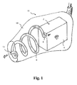
- Fig. 1 shows a part of an embodiment of a hearing aid with a receiver 2 placed in a receiver housing 4.
- the receiver 2 is configured to be placed in the ear of a user during use.
- the hearing aid further comprises a sound tube 6 acoustically connected to a sound port opening 8 of the receiver 2.
- the sound tube 6 has a spiral form along its longitudinal extension, thus exhibiting a longitudinal extension in infinitely many directions.
- the sound tube 6 is preferably formed or may be formed as an integral part of an eartip 10, and has preferably or may have a longitudinal length of at least 16 mm, such as around 18 to 40 mm.
- the eartip 10 with the sound tube 6 may be manufactured in one single piece using SLA or SLS technology, wherein the sound tube 6 is integrally formed as a channel within the eartip 10.
- the eartip 10 may according to one or more embodiments be manufactured in standard sizes. However, according to a preferred embodiment the illustrated eartip 10 is provided in a custom version that is individually shaped to fit within the ear of a particular user and having a sound tube 6 of a, possibly predefined, length according to the acoustical performance needed and within the physical limitation within the ear and or ear cannel of the user.
- the exact shape of the sound tube 6 does not have to be spiral formed as illustrated in Fig. 1 , but could be defined by a software program, picking at the receiver output port 8 and the opposite end 12 in front of the eartip 10.
- the eartip 10 forms an integral part of an earpiece 11.
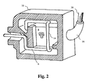
- Fig. 2 shows a cross section of a part of an alternative embodiment of a hearing aid with a receiver 2 placed in a receiver housing 4.
- the receiver 2 is configured to be placed in the ear of a user during use.
- the hearing aid further comprises a sound tube 6 acoustically connected to a sound port opening (not shown) of the receiver 2.
- the sound tube 6 has a piecewise linear form along its longitudinal extension, thus exhibiting a longitudinal extension in three different directions comprised in 8 linear pieces.
- the sound tube 6 is preferably formed or may be formed as an integral part of an eartip 10 (or earpiece, since the words eartip and earpiece are used interchangeably throughout the present patent specification).
- the eartip 10 with the sound tube 6 may be manufactured in one single piece using SLA or SLS technology, wherein the sound tube 6 is integrally formed as a channel within the eartip 10.
- the illustrated sound tube 6 abuts to the receiver housing 4 along the linear piece 14 of the sound tube 6.
- a smaller and more compact earpiece 11 is achieved.
- an electrical socket system 16 configured for providing an electrical connection between electrical terminals (not shown) of the receiver 2 and that part of the hearing aid which contains the audio signal processing unit (not shown) via an electrical wire 38.
- the electrical socket system 16 may be detachable.
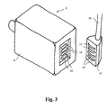
- Fig. 3 shows an embodiment of a part of a hearing aid according to the invention with a detachable electrical socket system 16 for providing an electrical connection between electrical terminals 18 of the receiver 2 and corresponding electrical terminals 19 on the electrical socket system 16, so that the receiver thereby can be operatively connected to that part of the hearing aid which contains the audio signal processing unit (not shown) via an electrical wire 38.
- Fig. 4 shows a perspective view of a cross section of a receiver 2 with a housing 4, to which housing a sound tube 6 is attached.
- the illustrated sound tube 6 has a rectangular cross section.
- the sound tube 6 thus has a large contact surface 20 that abuts to the housing 4 of the receiver 2. This has the effect that the spatial extension of the combined receiver 2 and sound tube 6 along the direction 22 is minimized as compared to using a sound tube 6 that has a circular cross section.
- Fig. 5 shows a perspective view of a cross section of an alternative space saving configuration of the sound tube 6 and receiver 2.
- the receiver 2 and eartip 10 with the sound tube 6 as illustrated in any of the figures 1 - 5 may in one or more embodiments form part of a so called ITE hearing aid.
- the illustrated receiver 2 and eartip 10 with the sound tube 6 may from part of a CIC hearing aid, and in yet an alternative embodiment the illustrated receiver 2 and eartip 10 with the sound tube 6 may from part of an earpiece for a RIE hearing aid.
- the sound tube 6 illustrated in one of the figures 1 - 5 may have a longitudinal length that is larger than the longitudinal extension of the receiver 2, and in an alternative embodiment the sound tube 6 as illustrated in one of the figures 2 - 5 may have a longitudinal length along one of the at least two directions that is larger than a longitudinal length of the receiver 2.
- the overall longitudinal length of the sound tube 6 illustrated in any of the figures 1 - 5 may be between 18 mm and 26 mm, even more preferably between 20 mm and 24 mm.
- Fig. 6 shows a part of a hearing aid according to a second aspect of the invention. Illustrated in Fig. 6 is an explosion view of a receiver 2 that is adapted to be placed at least partly in the ear or ear canal of a user.
- the receiver 2 comprises a motor 24 and a receiver housing made from the two pieces 26 and 28.
- the receiver housing has an integrally formed sound tube 6 which has a total length of at least 16 mm, such as around 18 to 40 mm, and a longitudinal extension in at least two directions.
- the sound tube 6 may in one or more embodiments be formed as an integral part of one of the pieces 26 or 28, or it may, as illustrated, be formed as an integral part of both of the pieces 26 or 28 as matching groves in booth of the housing pieces 26 and 28.
- the sound generated by the receiver motor 24 is then influenced by the sound tube 6 in such a way that it will be enhanced due to the resonance properties of the sound tube 6 before it is emitted through the sound output port 30 of the receiver 2.
- the receiver 2 may be operatively connected to another part of the hearing aid that contains a signal processing unit via a cable connection (not shown).
- Fig. 7 shows a hearing aid 34 according to a third aspect of the invention.
- the illustrated hearing aid 34 comprises a behind the ear (BTE) unit 36 configured to convert and process sound into an electrical signal and a signal conductor 38 (e.g. a wire) configured to communicate said electrical signal to an earpiece (not shown).
- the earpiece (not shown) comprises a receiver 2 that is configured to convert the electrical signal into a sound signal.
- the earpiece (not shown) further comprises a sound tube (not shown) that is connected to the sound port opening (not shown) of the receiver 2.
- the sound tube (not shown) has further a longitudinal extension in at least two directions.
- the earpiece may comprise a receiver 2 and sound tube 6 as illustrated in any of the embodiments shown in any of the figures 1 - 5 .
- the earpiece may comprise a receiver 2 as illustrated and explained with reference to Fig. 6 , wherein the sound tube 6 is formed as an integral part of the receiver housing provided by the two pieces 26 and 28.
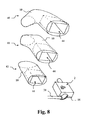
- Fig. 8 shows three earpieces 40, 41, 42 and a receiver 2.
- the earpieces 40, 41 and 42 may each comprise a sound tube (not shown) that may be forming an integral part of the tip portion 10 of said earpieces 40, 41 or 42, for example as illustrated in any of the figures 1 or 2 .
- the earpieces each have a cavity 44 that is adapted to receive the receiver 2 and which preferably snugly fits to at least a part of the outer contours of the receiver housing 4.
- the sound tube (not shown) may form an integral part of the receiver housing 4, as e.g. illustrated in figure 6 , in which case the earpieces 40, 41 or 42 therefore not need to have a sound tube integrated into them.
- the sound tube (not shown) could partly be formed in any of the earpieces 41, 41 or 42 and partly be formed in the housing 4 of the receiver 2.
- the receiver 2 is connected to a BTE unit (not shown) via a wire 38 that is connected to the receiver 2 via the electrical socket 16.
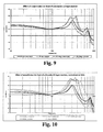
- Fig. 9 shows a comparison of simulated and measured frequency responses, with a constant voltage drive, with one exemplary sound tube (termed sound tube 1), compared to a response with no sound tube attached.
- the sound tube consists of two attached tubes of different length and cross section area with the following dimensions: 12 mm length with a diameter of 3 mm followed by a length of 10 mm having a diameter of 2.5 mm.
- a receiver that is fit for RIE/ITE applications is used for the actual measurements. In this example a Knowles type ED receiver has been used.
- the receiver has been measured and simulated under standard RIE conditions, i.e. with no sound tube between the receiver and the coupler (or the ear canal of a user).
- the IEC 711 ear simulator was used as the measurement coupler. This corresponds to conditions for standard RIE type of hearing aids known in the art.
- the result of this measurement is illustrated by the thick solid line (termed ED, bare, measurement) exhibiting a resonance peak around 3 kHz.
- the computer simulation of the same condition is given by the thin solid line (termed ED, bare, simulation). The difference in the measured in simulated responses do not have a significant impact in predicting the effect of the sound tube.
- the acoustic path is changed in two ways.
- the so called acoustic mass (which is proportional to US of the tube, where L is the length and S is the cross sectional area) is added in front of the receiver membrane.
- a waveguide is created which in one end is coupled to the receiver and wherein the other end of the sound tube is coupled with the ear canal (or a measurement coupler).
- the first resonance peak is around 3 kHz (see the solid lines) and that is the mechanical resonance of the receiver, which is determined by the stiffness of the suspension system and the mass of the moving system.
- the added acoustic mass in the sound tube is large enough to affect the mechanical resonance and it shifts a little bit lower in frequency (see the first resonance peak in the dashed lines as compared to the first resonance peak in the solid lines).
- the added acoustic mass also affects the resonance peak around 7 kHz - 8 kHz and fine tuning here can be beneficial for adjusting the system bandwidth.
- the waveguide effect creates an additional resonance peak, around 3.8kHz (the second resonance peak in dashed lines).
- the frequency of this resonance peak corresponds approximately to the quarter wavelength resonance of the sound tube.
- a hearing aid according to the invention is able to provide a higher output sound pressure level (which can readily be seen by comparing the dashed lines to the solid lines in Fig. 9 ) and a broader peak around 3 kHz (this can also be seen by comparing the dashed lines to the solid lines in Fig. 9 ) using the existing electrical hearing aid hardware, i.e. existing signal processor(s) and receiver(s) as compared to standard RIE type of hearing aids known in the art.
- the benefits of improved output are better dynamic range of the hearing aid, and, if stability allows, higher maximum gain.
- Fig. 10 shows another sound tube construction (termed sound tube 2) that basically has the same inner dimensions as tube 1.
- sound tube 2 is one that has a form similar to the form of the sound tube 6 illustrated in Fig. 2 .
- BTE CORFIG target hearing aid insertion loss curve
- a Knowles ED type receiver was chosen for the experiment and simulation. The difference between the ED shown in Fig. 9 is the absence of a sound port. The receiver responses are normalized to 1 kHz. Also here the IEC 711 ear simulator was used as the measurement coupler.
- the dotted line is a typical shape of the hearing aid insertion loss compensation curve for to a BTE device (which is also applicable to a RIE device), termed BTE CORFIG, typical shape.
- BTE CORFIG typical shape.
- the shape illustrated in Fig. 10 is also valid for the IEC 711 ear simulator.
- both dashed curves can match the CORFIG better than the solid curves (bare receiver, i.e. without sound tube).
- CORFIG is an acronym for Coupler Response for Flat Insertion gain.
- a hearing aid must be able to compensate for this insertion loss, for example by setting a suitable insertion gain in the hearing aid, before any hearing impairment correction gain can be applied.
- response targets are measured and defined.
- a compensation response (or gain) curve is defined for each hearing aid type, termed CORFIG, and a hearing aid must have a frequency response that is as close as possible to a given CORFIG in order to be able to properly compensate for the insertion loss.
- the exemplary hearing aid according to the invention has a response (the dashed curves) that fits much better to the typical CORFIG (dotted curve) of a BTE hearing aid.
- Fig. 11 shows a part of an embodiment of a hearing aid with a receiver 2 placed in a receiver housing 4. Since the illustrated embodiment shown in Fig. 11 is very similar to the one illustrated in Fig. 1 , only the differences will be described. In addition to the features already described with reference to Fig. 1 , the embodiment illustrated in Fig. 11 also comprises a second sound tube 46 that is connected to a microphone 46 in one end and has another free end with an opening 50. When the eartip 10 is placed in the ear canal of a user, the microphone 48 will be able to pick up the sound field within the ear canal of said user via the second sound tube 46.
- Fig. 12 shows a part of an embodiment of a hearing aid with a sound tube 6 having increasing cross sectional area.
- the sound tube 6 has an extension in two directions, but could in other embodiments have a longitudinal extension in more that two directions.
- a part of the illustrated sound tube 6 has three sections 52, 54 and 56 of stepwise increasing cross sectional area. This kind of sound tube enables additional degrees of freedom in designing a system with a certain desired frequency response.
- Fig. 13 shows a part of an embodiment of a hearing aid with a sound tube 6 having stepwise increasing and decreasing cross sectional areas.
- the sound tube 6 has a section 58 of increased cross sectional area followed by a section 60 of decreased cross sectional area, which in turn is followed by a section 62 of increased cross sectional area that again is followed by a section 64 of decreased cross sectional area.
- the cross sectional area of the sections 58 and 62 may be substantially equal or alternatively they may be different from each other.
- the cross sectional area of the sections 60 and 64 may be substantially equal or alternatively they may be different from each other.
- the sections 58 and 62 define two resonance chambers within the sound tube 6.
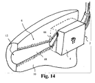
- Fig. 14 shows a part of an alternative embodiment of a hearing aid with a sound tube 6 having increasing cross sectional area.
- the sound tube 6 has two sections 66 and 68 each of which extending in a different direction along the longitudinal extension of the sound tube 6.
- the section 68 has a gradually, i.e. step less, increasing cross sectional area in the direction toward the sound output 12.
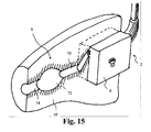
- Fig. 15 shows a part of an alternative embodiment of a hearing aid with a sound tube 6 having a gradually increasing and decreasing cross sectional area.
- the sound tube 6 has a section 70 followed by a section 72, that in turn is followed by a section 74.
- the section 72 has a gradually, i.e. step less, increasing and decreasing cross sectional area, whereby the sound tube section 72 defines a cavity or resonance chamber within the sound tube 6.
- the sound tube 6 illustrated in any of the figures 1 , 2 , 4 - 6 , and 11 - 15 may comprise a cerumen filter.
- the receiver may have a higher resonance frequency than around 3 kHz.
- a resonance frequency of the receiver may be around 3.5 kHz or around 4 kHz.
- the sound tube of the present invention is configured to generate a resonance frequency that is separated by e.g. around or not more than 1 kHz from the resonance frequency of the receiver.
- a separation of more than 1 kHz could make the "valley" in the frequency response between the resonance frequencies deeper than desired.
- the resonance frequency of the sound tube may be desired to be around 2.5 kHz or around 3 kHz, respectively.
- the tube resonance may be desired to be around 2.5 kHz (e.g. +/- 0.3 kHz).
- a sound tube having a total length of 3.5 cm e.g. +/- 3 mm or +/- 5 mm may be desired.
- the resonance of the tube may be desired to be around 3 kHz (e.g. +/- 0.3 kHz).
- a sound tube having a total length of around 2.6 cm e.g. +/- 3 mm or +/- 5 mm may be desired.
- the hearing aid according to the present invention may be configured such that the sound tube is situated within a first housing of the hearing aid.
- the sound tube may form an integral part with or may be at least substantially enclosed by the first housing.
- the first housing may be, may be formed as, or may comprise the receiver housing and/or an ear mould and/or an ear tip and/or an earpiece and/or any part of the hearing aid configured to be place at least partly in the ear canal of a user.
Landscapes
- Engineering & Computer Science (AREA)
- Manufacturing & Machinery (AREA)
- Health & Medical Sciences (AREA)
- General Health & Medical Sciences (AREA)
- Neurosurgery (AREA)
- Otolaryngology (AREA)
- Physics & Mathematics (AREA)
- Acoustics & Sound (AREA)
- Signal Processing (AREA)
- Headphones And Earphones (AREA)
- Soundproofing, Sound Blocking, And Sound Damping (AREA)
- Circuit For Audible Band Transducer (AREA)
Claims (15)
- Hörgerät mit einem in einem Empfängergehäuse angeordneten Empfänger, wobei der Empfänger zum Anordnen zumindest teilweise in dem Gehörgang eines Benutzers ausgebildet ist, wobei das Hörgerät ferner einen Schallschlauch umfasst, welcher mit einer Schallausgangsöffnung des Empfängers akustisch verbunden ist, und längliche Verlängerungen in zumindest zwei Richtungen aufweist, wobei der Schallschlauch ferner eine Gesamtlänge von etwa 18 bis 40 mm aufweist.
- Hörgerät nach Anspruch 1, wobei der Schallschlauch an das Empfängergehäuse entlang von zumindest einer der zumindest zwei Richtungen zumindest teilweise angrenzt.
- Hörgerät nach Anspruch 1 oder 2, wobei die Gesamtlänge des Schallschlauchs länger als eine Länge in Längsrichtung des Empfängers ist.
- Hörgerät nach Anspruch 1, 2 oder 3, wobei das Empfängergehäuse dazu ausgebildet ist, während der Verwendung völlig in dem Gehörgang eines Benutzers angeordnet zu werden.
- Hörgerät nach einem der vorgehenden Ansprüche, wobei eine Länge in Längsrichtung des Schallschlauchs entlang von einer der zumindest zwei Richtungen größer als eine Länge in Längsrichtung des Empfängers ist.
- Hörgerät nach einem der vorgehenden Ansprüche, wobei der Schallschlauch zumindest zwei verschiedene Querschnittsbereiche aufweist.
- Hörgerät nach einem der vorgehenden Ansprüche, wobei der Schallschlauch als ein integrierter Teil einer Hörmuschel mit einem abnehmbaren Steckdosensystem gebildet ist.
- Hörgerät nach einem der Ansprüche 1 - 7, wobei der Schallschlauch als ein vordefinierter Teil zum Montieren auf/bei einem Empfänger gebildet ist.
- Hörgerät nach einem der Ansprüche 1 - 6, wobei der Schallschlauch als ein integrierter Teil des Empfängergehäuses gebildet ist.
- Hörgerät nach einem der vorgehenden Ansprüche, wobei der Schallschlauch individuell gebildet ist, um eine auf den Endbenutzer bezogene Gestalt, Querschnitt(e) und Länge abhängig von den angeforderten akustischen Eigenschaften (z.B. Frequenzverstärkungsbereich, Dämpfungseigenschaften für Rückkopplungssperre) zu besitzen.
- Hörgerät nach einem der vorgehenden Ansprüche, wobei sich der Querschnittsbereich des Schallschlauchs von der Empfängerausgangsöffnung stufenweise oder schrittweise oder teilweise stufenweise und/oder teilweise schrittweise entlang von zumindest einem Teil der länglichen Verlängerungen des Schallschlauchs erhöht.
- Empfänger für ein Hörgerät, wobei der Empfänger dazu ausgebildet ist, zumindest teilweise in dem Gehörgang eines Benutzers angeordnet zu werden, wobei der Empfänger einen Motor und ein Empfängergehäuse umfasst, dadurch gekennzeichnet, dass das Empfängergehäuse einen integriert gebildeten Schallschlauch aufweist, welcher längliche Verlängerungen in zumindest zwei Richtungen aufweist, und wobei der Schallschlauch eine Gesamtlänge von etwa 18 bis 40 mm aufweist, wobei der Empfänger derart ausgebildet ist, dass von dem Empfängermotor erzeugter Schall über den Schallschlauch durch eine Schallausgangsöffnung des Empfängers ausgesendet wird.
- Hörgerät umfassend eine Hinter-dem-Ohr- (HdO-) Einheit, welche dazu ausgebildet ist, Schall in ein elektrisches Signal umzuwandeln und zu verarbeiten, und einen Signalleiter, welcher dazu ausgebildet ist, das elektrische Signal an eine Hörmuschel zu kommunizieren, wobei die Hörmuschel einen Empfänger umfasst, welcher dazu ausgebildet ist, das elektrische Signal in ein Schallsignal umzuwandeln, dadurch gekennzeichnet, dass die Hörmuschel einen Schallschlauch umfasst, welcher mit einer Schallausgangsöffnung des Empfängers verbunden ist und längliche Verlängerungen in zumindest zwei Richtungen aufweist und eine Gesamtlänge von etwa 18 bis 40 mm aufweist.
- Hörgerät nach einem der Ansprüche 1-11, wobei die Gesamtlänge des Schallschlauchs derart ausgebildet ist, dass eine Resonanzfrequenz des Schallschlauchs etwa 1 kHz von einer ersten Resonanzfrequenz des Empfängers beträgt.
- Verfahren zum Liefern von Schall an einen Benutzer eines Hörgeräts mittels eines Hörgeräts mit einem in einem Empfängergehäuse angeordneten Empfänger, wobei der Empfänger zum Anordnen zumindest teilweise in dem Gehörgang eines Benutzers ausgebildet ist, wobei das Hörgerät ferner einen Schallschlauch umfasst, wobei der Schallschlauch längliche Verlängerungen in zumindest zwei Richtungen aufweist und eine Gesamtlänge von etwa 18 bis 40 mm aufweist, wobei das Verfahren das Liefern von Schall von dem Empfänger an den Benutzer über den Schallschlauch umfasst.
Priority Applications (1)
| Application Number | Priority Date | Filing Date | Title |
|---|---|---|---|
| EP11720287.9A EP2559264B1 (de) | 2010-04-14 | 2011-04-14 | Hörgerät mit schallschlauch |
Applications Claiming Priority (4)
| Application Number | Priority Date | Filing Date | Title |
|---|---|---|---|
| EP10159929A EP2378792A1 (de) | 2010-04-14 | 2010-04-14 | Hörgerät mit Schallschlauch |
| US13/084,506 US9210522B2 (en) | 2010-04-14 | 2011-04-11 | Hearing aid |
| PCT/DK2011/000029 WO2011127932A1 (en) | 2010-04-14 | 2011-04-14 | Hearing aid with sound tube |
| EP11720287.9A EP2559264B1 (de) | 2010-04-14 | 2011-04-14 | Hörgerät mit schallschlauch |
Publications (2)
| Publication Number | Publication Date |
|---|---|
| EP2559264A1 EP2559264A1 (de) | 2013-02-20 |
| EP2559264B1 true EP2559264B1 (de) | 2015-05-27 |
Family
ID=42732529
Family Applications (2)
| Application Number | Title | Priority Date | Filing Date |
|---|---|---|---|
| EP10159929A Withdrawn EP2378792A1 (de) | 2010-04-14 | 2010-04-14 | Hörgerät mit Schallschlauch |
| EP11720287.9A Active EP2559264B1 (de) | 2010-04-14 | 2011-04-14 | Hörgerät mit schallschlauch |
Family Applications Before (1)
| Application Number | Title | Priority Date | Filing Date |
|---|---|---|---|
| EP10159929A Withdrawn EP2378792A1 (de) | 2010-04-14 | 2010-04-14 | Hörgerät mit Schallschlauch |
Country Status (6)
| Country | Link |
|---|---|
| US (1) | US9210522B2 (de) |
| EP (2) | EP2378792A1 (de) |
| JP (1) | JP5764199B2 (de) |
| CN (2) | CN103404173B (de) |
| DK (1) | DK2559264T3 (de) |
| WO (1) | WO2011127932A1 (de) |
Cited By (1)
| Publication number | Priority date | Publication date | Assignee | Title |
|---|---|---|---|---|
| EP3437330B1 (de) | 2016-04-01 | 2021-06-09 | Widex A/S | Aufhängung eines hörers in einem hörgerät |
Families Citing this family (29)
| Publication number | Priority date | Publication date | Assignee | Title |
|---|---|---|---|---|
| JP4913256B1 (ja) * | 2011-07-05 | 2012-04-11 | 勇 小泉 | カナル型受話器用イヤーピース及びそれを利用したカナル型受話器、並びにカナル型受話器を利用した聴診器及び補聴器 |
| DK2608576T3 (en) * | 2011-12-21 | 2020-03-30 | Sonion Nederland Bv | An apparatus and a method for providing sound |
| WO2013106342A1 (en) * | 2012-01-09 | 2013-07-18 | Voxx International Corporation | Personal sound amplifier |
| DK2654322T3 (da) | 2012-04-20 | 2016-12-05 | Sivantos Pte Ltd | Høreinstrument med lydslange-stikforbindelse |
| EP2663096A1 (de) * | 2012-05-07 | 2013-11-13 | Starkey Laboratories, Inc. | Verfahren zur akustischen Belastung des Empfängers einer Hörhilfevorrichtung |
| US8983101B2 (en) | 2012-05-22 | 2015-03-17 | Shure Acquisition Holdings, Inc. | Earphone assembly |
| US9241209B2 (en) | 2013-06-25 | 2016-01-19 | Google Inc. | Headphones with adaptable fit |
| USD719131S1 (en) | 2013-06-25 | 2014-12-09 | Google Inc. | Headphone assembly |
| USD719132S1 (en) | 2013-06-25 | 2014-12-09 | Google Inc. | Headphone assembly |
| US20150172827A1 (en) * | 2013-12-17 | 2015-06-18 | United Sciences, Llc | Identity confirmation using wearable computerized earpieces and related methods |
| US20150172832A1 (en) * | 2013-12-17 | 2015-06-18 | United Sciences, Llc | Iidentity confirmation using wearable computerized earpieces and related methods |
| EP3211917B1 (de) * | 2014-10-24 | 2020-02-26 | Sony Corporation | Ohrhörer |
| CN104378726B (zh) * | 2014-11-05 | 2018-03-20 | 丽声助听器(福州)有限公司 | 带物理导声模块助听器 |
| US10063958B2 (en) | 2014-11-07 | 2018-08-28 | Microsoft Technology Licensing, Llc | Earpiece attachment devices |
| US20160134958A1 (en) * | 2014-11-07 | 2016-05-12 | Microsoft Technology Licensing, Llc | Sound transmission systems and devices having earpieces |
| KR101831575B1 (ko) * | 2015-01-19 | 2018-02-22 | 쓰리엠 이노베이티브 프로퍼티즈 캄파니 | 회선형 음향 혼을 가진 청력 보호 장치 |
| EP3086574A3 (de) * | 2015-04-20 | 2017-03-15 | Oticon A/s | Hörgerätevorrichtung und hörgerätevorrichtungssystem |
| DE102016205728B3 (de) * | 2016-04-06 | 2017-07-27 | Sivantos Pte. Ltd. | Verfahren zur physischen Anpassung eines Hörgeräts, Hörgerät und Hörgerätesystem |
| DE102017207528A1 (de) * | 2017-05-04 | 2018-11-08 | Sivantos Pte. Ltd. | Modul zum Einbau in ein Hörhilfegerät |
| USD890696S1 (en) | 2017-07-21 | 2020-07-21 | Google Llc | Earbud charging case |
| USD867326S1 (en) | 2017-07-21 | 2019-11-19 | Google Llc | Wireless earbuds |
| USD896781S1 (en) | 2017-08-04 | 2020-09-22 | Google Llc | Audio assembly |
| USD844586S1 (en) | 2017-08-04 | 2019-04-02 | Google Llc | Audio assembly |
| DE102017214942A1 (de) * | 2017-08-25 | 2019-02-28 | Sivantos Pte. Ltd. | Verfahren zum Anpassen einer Hörvorrichtung |
| US11246755B2 (en) | 2017-11-17 | 2022-02-15 | Microsonic, Inc. | Sound attenuation earplug system and method of manufacture |
| USD879075S1 (en) | 2018-07-11 | 2020-03-24 | Google Llc | Earbud stand assembly |
| US11659312B2 (en) | 2019-08-05 | 2023-05-23 | Audiolineout Llc | Earphone with solid body |
| US11470428B2 (en) * | 2020-07-30 | 2022-10-11 | Meta Platforms Technologies, Llc | Personalized calibration of an in-ear device |
| CN115175077B (zh) * | 2022-07-20 | 2024-09-17 | 厦门瑞听听力科技有限公司 | 一种声管可调型智能助听器 |
Family Cites Families (26)
| Publication number | Priority date | Publication date | Assignee | Title |
|---|---|---|---|---|
| JPS5843700A (ja) | 1981-09-09 | 1983-03-14 | Rion Co Ltd | 插耳形補聴器 |
| US5002151A (en) * | 1986-12-05 | 1991-03-26 | Minnesota Mining And Manufacturing Company | Ear piece having disposable, compressible polymeric foam sleeve |
| JPH0533120Y2 (de) * | 1987-07-15 | 1993-08-24 | ||
| FR2657716B1 (fr) * | 1990-02-01 | 1995-07-13 | Leher Francois | Dispositif de transmission du son a filtrage selectif, destine a etre mis en place dans le conduit auditif externe. |
| US5068901A (en) | 1990-05-01 | 1991-11-26 | Knowles Electronics, Inc. | Dual outlet passage hearing aid transducer |
| JPH05115092A (ja) * | 1991-10-21 | 1993-05-07 | Pilot Corp:The | 外耳道挿入型イヤピース |
| US5701348A (en) | 1994-12-29 | 1997-12-23 | Decibel Instruments, Inc. | Articulated hearing device |
| US5987146A (en) * | 1997-04-03 | 1999-11-16 | Resound Corporation | Ear canal microphone |
| US6205227B1 (en) * | 1998-01-31 | 2001-03-20 | Sarnoff Corporation | Peritympanic hearing instrument |
| JPH11234783A (ja) * | 1998-02-13 | 1999-08-27 | Masaaki Takenaka | スピーカシステム |
| US6724902B1 (en) * | 1999-04-29 | 2004-04-20 | Insound Medical, Inc. | Canal hearing device with tubular insert |
| US7110562B1 (en) * | 2001-08-10 | 2006-09-19 | Hear-Wear Technologies, Llc | BTE/CIC auditory device and modular connector system therefor |
| JP3742330B2 (ja) * | 2001-10-31 | 2006-02-01 | スター精密株式会社 | 挿入型イヤホン |
| JP2005533453A (ja) * | 2002-07-18 | 2005-11-04 | インサウンド メディカル, インコーポレイテッド | 管状挿入物を伴う耳道聴覚装置 |
| DE102004025122A1 (de) * | 2004-05-21 | 2005-12-22 | Siemens Audiologische Technik Gmbh | Hörgerät mit abgespeichertem, individuellem Frequenzgang und entsprechendes Anpassverfahren |
| US7369670B2 (en) * | 2004-08-25 | 2008-05-06 | Phonak Ag | Earplug and method for manufacturing the same |
| DK2416589T3 (en) * | 2004-11-01 | 2018-03-12 | Sonion Nederland Bv | Electroacoustic transducer and transducer device |
| US7844065B2 (en) * | 2005-01-14 | 2010-11-30 | Phonak Ag | Hearing instrument |
| US7748495B2 (en) * | 2005-04-20 | 2010-07-06 | Krueger Paul M | Tubular loudspeaker |
| DE102006001847A1 (de) * | 2006-01-13 | 2007-07-19 | Siemens Audiologische Technik Gmbh | Verfahren zum Formen eines Schallkanals einer Hörvorrichtung |
| AU2007356359B2 (en) * | 2007-07-10 | 2011-03-31 | Widex A/S | Method for identifying a receiver in a hearing aid |
| DE102007046052A1 (de) * | 2007-09-26 | 2009-04-09 | Siemens Medical Instruments Pte. Ltd. | Schallschlauch für eine Hörvorrichtung |
| US8019107B2 (en) * | 2008-02-20 | 2011-09-13 | Think-A-Move Ltd. | Earset assembly having acoustic waveguide |
| JP2012510222A (ja) * | 2008-12-11 | 2012-04-26 | ヴェーデクス・アクティーセルスカプ | 補聴器イヤピースおよび補聴器イヤピースを製造する方法 |
| EP2415278A4 (de) * | 2009-04-01 | 2013-05-15 | Knowles Electronics Llc | Empfängeranordnungen |
| US20110051977A1 (en) * | 2009-08-28 | 2011-03-03 | Losko David J | Ear Canal Microphone |
-
2010
- 2010-04-14 EP EP10159929A patent/EP2378792A1/de not_active Withdrawn
-
2011
- 2011-04-11 US US13/084,506 patent/US9210522B2/en active Active
- 2011-04-14 WO PCT/DK2011/000029 patent/WO2011127932A1/en not_active Ceased
- 2011-04-14 CN CN201180029191.9A patent/CN103404173B/zh active Active
- 2011-04-14 EP EP11720287.9A patent/EP2559264B1/de active Active
- 2011-04-14 CN CN201710141449.3A patent/CN106921924B/zh active Active
- 2011-04-14 JP JP2013504122A patent/JP5764199B2/ja not_active Expired - Fee Related
- 2011-04-14 DK DK11720287.9T patent/DK2559264T3/en active
Cited By (1)
| Publication number | Priority date | Publication date | Assignee | Title |
|---|---|---|---|---|
| EP3437330B1 (de) | 2016-04-01 | 2021-06-09 | Widex A/S | Aufhängung eines hörers in einem hörgerät |
Also Published As
| Publication number | Publication date |
|---|---|
| EP2378792A1 (de) | 2011-10-19 |
| US20110255723A1 (en) | 2011-10-20 |
| JP5764199B2 (ja) | 2015-08-12 |
| CN103404173A (zh) | 2013-11-20 |
| CN106921924B (zh) | 2020-05-19 |
| DK2559264T3 (en) | 2015-08-31 |
| JP2013524704A (ja) | 2013-06-17 |
| EP2559264A1 (de) | 2013-02-20 |
| US9210522B2 (en) | 2015-12-08 |
| WO2011127932A1 (en) | 2011-10-20 |
| CN103404173B (zh) | 2017-11-03 |
| CN106921924A (zh) | 2017-07-04 |
Similar Documents
| Publication | Publication Date | Title |
|---|---|---|
| DK2559264T3 (en) | Hearing the sound tube | |
| US8437489B2 (en) | Hearing instrument | |
| US10136228B2 (en) | Hearing aid device and method for feedback reduction | |
| CN101010984B (zh) | 骨传导助听装置 | |
| US8625831B2 (en) | Hearing aid earpiece and a method of manufacturing a hearing aid earpiece | |
| US8165332B2 (en) | Earpiece with bars | |
| DK2671391T3 (en) | Hearing device with a transducer module and method for manufacturing a transducer module | |
| EP2432254B1 (de) | Hörgerät | |
| EP2405674A2 (de) | Hörhilfe mit Einschlussunterdrückung | |
| US20080253595A1 (en) | Method for adjusting a binaural hearing device system | |
| CN105556989A (zh) | 具有提高的低频响应的听力装置以及用于制造这种听力装置的方法 | |
| EP4044623A1 (de) | Hörgerät mit einer entlüftung und einem akustischen ventil | |
| US11395077B2 (en) | Hearing device with vent | |
| US11178497B2 (en) | In-ear receiver | |
| CN105122842A (zh) | 耳背式助听器 | |
| CN118160323A (zh) | 耳插入件 | |
| US20080298620A1 (en) | Wearing hook with metal section for a hearing device |
Legal Events
| Date | Code | Title | Description |
|---|---|---|---|
| PUAI | Public reference made under article 153(3) epc to a published international application that has entered the european phase |
Free format text: ORIGINAL CODE: 0009012 |
|
| 17P | Request for examination filed |
Effective date: 20121114 |
|
| AK | Designated contracting states |
Kind code of ref document: A1 Designated state(s): AL AT BE BG CH CY CZ DE DK EE ES FI FR GB GR HR HU IE IS IT LI LT LU LV MC MK MT NL NO PL PT RO RS SE SI SK SM TR |
|
| RIN1 | Information on inventor provided before grant (corrected) |
Inventor name: NIELSEN, HENRIK Inventor name: OBRADOVIC, GOJKO Inventor name: KRISTENSEN, POUL, ROSENKILDE |
|
| DAX | Request for extension of the european patent (deleted) | ||
| GRAP | Despatch of communication of intention to grant a patent |
Free format text: ORIGINAL CODE: EPIDOSNIGR1 |
|
| INTG | Intention to grant announced |
Effective date: 20141027 |
|
| GRAS | Grant fee paid |
Free format text: ORIGINAL CODE: EPIDOSNIGR3 |
|
| GRAA | (expected) grant |
Free format text: ORIGINAL CODE: 0009210 |
|
| AK | Designated contracting states |
Kind code of ref document: B1 Designated state(s): AL AT BE BG CH CY CZ DE DK EE ES FI FR GB GR HR HU IE IS IT LI LT LU LV MC MK MT NL NO PL PT RO RS SE SI SK SM TR |
|
| REG | Reference to a national code |
Ref country code: GB Ref legal event code: FG4D |
|
| REG | Reference to a national code |
Ref country code: CH Ref legal event code: EP |
|
| REG | Reference to a national code |
Ref country code: AT Ref legal event code: REF Ref document number: 729381 Country of ref document: AT Kind code of ref document: T Effective date: 20150615 |
|
| REG | Reference to a national code |
Ref country code: IE Ref legal event code: FG4D |
|
| REG | Reference to a national code |
Ref country code: DE Ref legal event code: R096 Ref document number: 602011016759 Country of ref document: DE |
|
| REG | Reference to a national code |
Ref country code: DK Ref legal event code: T3 Effective date: 20150828 |
|
| REG | Reference to a national code |
Ref country code: AT Ref legal event code: MK05 Ref document number: 729381 Country of ref document: AT Kind code of ref document: T Effective date: 20150527 |
|
| REG | Reference to a national code |
Ref country code: LT Ref legal event code: MG4D |
|
| PG25 | Lapsed in a contracting state [announced via postgrant information from national office to epo] |
Ref country code: LT Free format text: LAPSE BECAUSE OF FAILURE TO SUBMIT A TRANSLATION OF THE DESCRIPTION OR TO PAY THE FEE WITHIN THE PRESCRIBED TIME-LIMIT Effective date: 20150527 Ref country code: FI Free format text: LAPSE BECAUSE OF FAILURE TO SUBMIT A TRANSLATION OF THE DESCRIPTION OR TO PAY THE FEE WITHIN THE PRESCRIBED TIME-LIMIT Effective date: 20150527 Ref country code: NO Free format text: LAPSE BECAUSE OF FAILURE TO SUBMIT A TRANSLATION OF THE DESCRIPTION OR TO PAY THE FEE WITHIN THE PRESCRIBED TIME-LIMIT Effective date: 20150827 Ref country code: ES Free format text: LAPSE BECAUSE OF FAILURE TO SUBMIT A TRANSLATION OF THE DESCRIPTION OR TO PAY THE FEE WITHIN THE PRESCRIBED TIME-LIMIT Effective date: 20150527 Ref country code: PT Free format text: LAPSE BECAUSE OF FAILURE TO SUBMIT A TRANSLATION OF THE DESCRIPTION OR TO PAY THE FEE WITHIN THE PRESCRIBED TIME-LIMIT Effective date: 20150928 Ref country code: HR Free format text: LAPSE BECAUSE OF FAILURE TO SUBMIT A TRANSLATION OF THE DESCRIPTION OR TO PAY THE FEE WITHIN THE PRESCRIBED TIME-LIMIT Effective date: 20150527 |
|
| REG | Reference to a national code |
Ref country code: NL Ref legal event code: MP Effective date: 20150527 |
|
| PG25 | Lapsed in a contracting state [announced via postgrant information from national office to epo] |
Ref country code: IS Free format text: LAPSE BECAUSE OF FAILURE TO SUBMIT A TRANSLATION OF THE DESCRIPTION OR TO PAY THE FEE WITHIN THE PRESCRIBED TIME-LIMIT Effective date: 20150927 Ref country code: AT Free format text: LAPSE BECAUSE OF FAILURE TO SUBMIT A TRANSLATION OF THE DESCRIPTION OR TO PAY THE FEE WITHIN THE PRESCRIBED TIME-LIMIT Effective date: 20150527 Ref country code: BG Free format text: LAPSE BECAUSE OF FAILURE TO SUBMIT A TRANSLATION OF THE DESCRIPTION OR TO PAY THE FEE WITHIN THE PRESCRIBED TIME-LIMIT Effective date: 20150827 Ref country code: GR Free format text: LAPSE BECAUSE OF FAILURE TO SUBMIT A TRANSLATION OF THE DESCRIPTION OR TO PAY THE FEE WITHIN THE PRESCRIBED TIME-LIMIT Effective date: 20150828 Ref country code: LV Free format text: LAPSE BECAUSE OF FAILURE TO SUBMIT A TRANSLATION OF THE DESCRIPTION OR TO PAY THE FEE WITHIN THE PRESCRIBED TIME-LIMIT Effective date: 20150527 Ref country code: RS Free format text: LAPSE BECAUSE OF FAILURE TO SUBMIT A TRANSLATION OF THE DESCRIPTION OR TO PAY THE FEE WITHIN THE PRESCRIBED TIME-LIMIT Effective date: 20150527 |
|
| PG25 | Lapsed in a contracting state [announced via postgrant information from national office to epo] |
Ref country code: EE Free format text: LAPSE BECAUSE OF FAILURE TO SUBMIT A TRANSLATION OF THE DESCRIPTION OR TO PAY THE FEE WITHIN THE PRESCRIBED TIME-LIMIT Effective date: 20150527 |
|
| PG25 | Lapsed in a contracting state [announced via postgrant information from national office to epo] |
Ref country code: SK Free format text: LAPSE BECAUSE OF FAILURE TO SUBMIT A TRANSLATION OF THE DESCRIPTION OR TO PAY THE FEE WITHIN THE PRESCRIBED TIME-LIMIT Effective date: 20150527 Ref country code: PL Free format text: LAPSE BECAUSE OF FAILURE TO SUBMIT A TRANSLATION OF THE DESCRIPTION OR TO PAY THE FEE WITHIN THE PRESCRIBED TIME-LIMIT Effective date: 20150527 Ref country code: RO Free format text: LAPSE BECAUSE OF NON-PAYMENT OF DUE FEES Effective date: 20150527 Ref country code: CZ Free format text: LAPSE BECAUSE OF FAILURE TO SUBMIT A TRANSLATION OF THE DESCRIPTION OR TO PAY THE FEE WITHIN THE PRESCRIBED TIME-LIMIT Effective date: 20150527 |
|
| REG | Reference to a national code |
Ref country code: DE Ref legal event code: R097 Ref document number: 602011016759 Country of ref document: DE |
|
| PLBE | No opposition filed within time limit |
Free format text: ORIGINAL CODE: 0009261 |
|
| STAA | Information on the status of an ep patent application or granted ep patent |
Free format text: STATUS: NO OPPOSITION FILED WITHIN TIME LIMIT |
|
| REG | Reference to a national code |
Ref country code: FR Ref legal event code: PLFP Year of fee payment: 6 |
|
| PG25 | Lapsed in a contracting state [announced via postgrant information from national office to epo] |
Ref country code: IT Free format text: LAPSE BECAUSE OF FAILURE TO SUBMIT A TRANSLATION OF THE DESCRIPTION OR TO PAY THE FEE WITHIN THE PRESCRIBED TIME-LIMIT Effective date: 20150527 |
|
| 26N | No opposition filed |
Effective date: 20160301 |
|
| PG25 | Lapsed in a contracting state [announced via postgrant information from national office to epo] |
Ref country code: SI Free format text: LAPSE BECAUSE OF FAILURE TO SUBMIT A TRANSLATION OF THE DESCRIPTION OR TO PAY THE FEE WITHIN THE PRESCRIBED TIME-LIMIT Effective date: 20150527 |
|
| PG25 | Lapsed in a contracting state [announced via postgrant information from national office to epo] |
Ref country code: BE Free format text: LAPSE BECAUSE OF FAILURE TO SUBMIT A TRANSLATION OF THE DESCRIPTION OR TO PAY THE FEE WITHIN THE PRESCRIBED TIME-LIMIT Effective date: 20150527 |
|
| PG25 | Lapsed in a contracting state [announced via postgrant information from national office to epo] |
Ref country code: LU Free format text: LAPSE BECAUSE OF FAILURE TO SUBMIT A TRANSLATION OF THE DESCRIPTION OR TO PAY THE FEE WITHIN THE PRESCRIBED TIME-LIMIT Effective date: 20160414 |
|
| REG | Reference to a national code |
Ref country code: IE Ref legal event code: MM4A |
|
| REG | Reference to a national code |
Ref country code: FR Ref legal event code: PLFP Year of fee payment: 7 |
|
| PG25 | Lapsed in a contracting state [announced via postgrant information from national office to epo] |
Ref country code: IE Free format text: LAPSE BECAUSE OF NON-PAYMENT OF DUE FEES Effective date: 20160414 |
|
| PG25 | Lapsed in a contracting state [announced via postgrant information from national office to epo] |
Ref country code: NL Free format text: LAPSE BECAUSE OF FAILURE TO SUBMIT A TRANSLATION OF THE DESCRIPTION OR TO PAY THE FEE WITHIN THE PRESCRIBED TIME-LIMIT Effective date: 20150527 Ref country code: SE Free format text: LAPSE BECAUSE OF FAILURE TO SUBMIT A TRANSLATION OF THE DESCRIPTION OR TO PAY THE FEE WITHIN THE PRESCRIBED TIME-LIMIT Effective date: 20150527 |
|
| REG | Reference to a national code |
Ref country code: FR Ref legal event code: PLFP Year of fee payment: 8 |
|
| PG25 | Lapsed in a contracting state [announced via postgrant information from national office to epo] |
Ref country code: HU Free format text: LAPSE BECAUSE OF FAILURE TO SUBMIT A TRANSLATION OF THE DESCRIPTION OR TO PAY THE FEE WITHIN THE PRESCRIBED TIME-LIMIT; INVALID AB INITIO Effective date: 20110414 Ref country code: SM Free format text: LAPSE BECAUSE OF FAILURE TO SUBMIT A TRANSLATION OF THE DESCRIPTION OR TO PAY THE FEE WITHIN THE PRESCRIBED TIME-LIMIT Effective date: 20150527 Ref country code: CY Free format text: LAPSE BECAUSE OF FAILURE TO SUBMIT A TRANSLATION OF THE DESCRIPTION OR TO PAY THE FEE WITHIN THE PRESCRIBED TIME-LIMIT Effective date: 20150527 |
|
| PG25 | Lapsed in a contracting state [announced via postgrant information from national office to epo] |
Ref country code: TR Free format text: LAPSE BECAUSE OF FAILURE TO SUBMIT A TRANSLATION OF THE DESCRIPTION OR TO PAY THE FEE WITHIN THE PRESCRIBED TIME-LIMIT Effective date: 20150527 Ref country code: MK Free format text: LAPSE BECAUSE OF FAILURE TO SUBMIT A TRANSLATION OF THE DESCRIPTION OR TO PAY THE FEE WITHIN THE PRESCRIBED TIME-LIMIT Effective date: 20150527 Ref country code: MC Free format text: LAPSE BECAUSE OF FAILURE TO SUBMIT A TRANSLATION OF THE DESCRIPTION OR TO PAY THE FEE WITHIN THE PRESCRIBED TIME-LIMIT Effective date: 20150527 Ref country code: MT Free format text: LAPSE BECAUSE OF NON-PAYMENT OF DUE FEES Effective date: 20160430 |
|
| PG25 | Lapsed in a contracting state [announced via postgrant information from national office to epo] |
Ref country code: AL Free format text: LAPSE BECAUSE OF FAILURE TO SUBMIT A TRANSLATION OF THE DESCRIPTION OR TO PAY THE FEE WITHIN THE PRESCRIBED TIME-LIMIT Effective date: 20150527 |
|
| REG | Reference to a national code |
Ref country code: FR Ref legal event code: PLFP Year of fee payment: 13 |
|
| P01 | Opt-out of the competence of the unified patent court (upc) registered |
Effective date: 20230525 |
|
| PGFP | Annual fee paid to national office [announced via postgrant information from national office to epo] |
Ref country code: DE Payment date: 20250423 Year of fee payment: 15 |
|
| PGFP | Annual fee paid to national office [announced via postgrant information from national office to epo] |
Ref country code: DK Payment date: 20250422 Year of fee payment: 15 |
|
| PGFP | Annual fee paid to national office [announced via postgrant information from national office to epo] |
Ref country code: FR Payment date: 20250417 Year of fee payment: 15 |
|
| PGFP | Annual fee paid to national office [announced via postgrant information from national office to epo] |
Ref country code: CH Payment date: 20250501 Year of fee payment: 15 |
|
| PGFP | Annual fee paid to national office [announced via postgrant information from national office to epo] |
Ref country code: GB Payment date: 20260317 Year of fee payment: 16 |
|
| REG | Reference to a national code |
Ref country code: CH Ref legal event code: U11 Free format text: ST27 STATUS EVENT CODE: U-0-0-U10-U11 (AS PROVIDED BY THE NATIONAL OFFICE) Effective date: 20260501 |