EP2558648B1 - Structure de fondations en mer, fondations en mer et son procédé d'établissement - Google Patents
Structure de fondations en mer, fondations en mer et son procédé d'établissement Download PDFInfo
- Publication number
- EP2558648B1 EP2558648B1 EP10779288.9A EP10779288A EP2558648B1 EP 2558648 B1 EP2558648 B1 EP 2558648B1 EP 10779288 A EP10779288 A EP 10779288A EP 2558648 B1 EP2558648 B1 EP 2558648B1
- Authority
- EP
- European Patent Office
- Prior art keywords
- seabed
- offshore foundation
- tube
- foundation structure
- main tube
- Prior art date
- Legal status (The legal status is an assumption and is not a legal conclusion. Google has not performed a legal analysis and makes no representation as to the accuracy of the status listed.)
- Not-in-force
Links
Images
Classifications
-
- E—FIXED CONSTRUCTIONS
- E02—HYDRAULIC ENGINEERING; FOUNDATIONS; SOIL SHIFTING
- E02B—HYDRAULIC ENGINEERING
- E02B17/00—Artificial islands mounted on piles or like supports, e.g. platforms on raisable legs or offshore constructions; Construction methods therefor
- E02B17/02—Artificial islands mounted on piles or like supports, e.g. platforms on raisable legs or offshore constructions; Construction methods therefor placed by lowering the supporting construction to the bottom, e.g. with subsequent fixing thereto
- E02B17/027—Artificial islands mounted on piles or like supports, e.g. platforms on raisable legs or offshore constructions; Construction methods therefor placed by lowering the supporting construction to the bottom, e.g. with subsequent fixing thereto steel structures
-
- E—FIXED CONSTRUCTIONS
- E02—HYDRAULIC ENGINEERING; FOUNDATIONS; SOIL SHIFTING
- E02D—FOUNDATIONS; EXCAVATIONS; EMBANKMENTS; UNDERGROUND OR UNDERWATER STRUCTURES
- E02D27/00—Foundations as substructures
- E02D27/32—Foundations for special purposes
- E02D27/42—Foundations for poles, masts or chimneys
-
- E—FIXED CONSTRUCTIONS
- E02—HYDRAULIC ENGINEERING; FOUNDATIONS; SOIL SHIFTING
- E02D—FOUNDATIONS; EXCAVATIONS; EMBANKMENTS; UNDERGROUND OR UNDERWATER STRUCTURES
- E02D27/00—Foundations as substructures
- E02D27/32—Foundations for special purposes
- E02D27/52—Submerged foundations, i.e. submerged in open water
-
- E—FIXED CONSTRUCTIONS
- E02—HYDRAULIC ENGINEERING; FOUNDATIONS; SOIL SHIFTING
- E02D—FOUNDATIONS; EXCAVATIONS; EMBANKMENTS; UNDERGROUND OR UNDERWATER STRUCTURES
- E02D7/00—Methods or apparatus for placing sheet pile bulkheads, piles, mouldpipes, or other moulds
- E02D7/20—Placing by pressure or pulling power
Definitions
- the present invention relates to an offshore foundation structure and, in particular, to a wind turbine offshore foundation structure.
- the invention relates to an offshore foundation, in particular to a wind turbine offshore foundation, and to a method of establishing such an offshore foundation.
- a jacket construction is, for example, shown in US 5,988,949 or in EP 2 067 914 A2 , a tripod construction, for example, in DE 10 2004 042 066 A1 .
- a typical method for establishing a foundation based on a jacked construction or a tripod construction is to prepare the seabed prior to establishing the foundation which includes levelling out variations of the height of the seabed in order to achieve a construction in level. Furthermore, the method comprises establishing piles very accurately positioned in the seabed such as by means of a pre-fabricated and pre-positioned pile positioning template structure on the seabed.
- GB 2460172 A discloses a method of installing a pile in the seabed in which method a guide structure for the pile is used.
- the guide structure comprises a tubular column/support that is carried on four footings.
- a tubular pile which is to be installed into a socket in the seabed is supplied within a vertical column/support, as it is shown in the figure as a hidden component.
- Each footing stands on an adjustable foot which is capable of being moved through some small distance vertically as well as being attached in the pivotable manner.
- the guide structure will be totally or partly removed after installing the pile.
- WO 2009/155639 A1 describes a drilling platform for geological sample drilling.
- a plurality of legs extend from the platform to the ground and are of variable lengths, which allows the platform to be set horizontally even on uneven ground.
- WO 2005/040605 A1 describes an offshore foundation for a wind energy plant.
- the offshore foundation comprises a number of legs with piles located inside the legs. The piles can be rammed into the seabed. From this document the features of the preamble of claim 1 are known.
- EP 1 707 808 A2 describes feet for an offshore wind energy plant which may be anchored in the seabed by use of piles driven through the feet.
- the piles are established by using e.g. hydraulic driven means which literally hammer the pile down into the seabed.
- a jacket or a tripod construction is set over a part of the pile (or piles in case of a tripod construction) and the space between the leg and the pile is grouted to establish a secure connection.
- the first objective is solved by an offshore foundation structure as claimed in claim 1 and by an offshore foundation as claimed in claim 5.
- the second objective is solved by a method of establishing an offshore foundation as claimed in claim 9.
- the depending claims contain further developments of the present invention.
- An inventive offshore foundation structure which may, in particular, be a wind turbine foundation structure, i.e. a foundation structure for carrying a wind turbine tower comprises at least one leg to be positioned on the seabed.
- a foundation structure is formed as jacket structure or a tripod structure with three legs resting on the seabed.
- the at least one leg of the inventive offshore foundation structure comprises an adjusting means which is able to, and prepared for, adjusting the axial length of the leg.
- the at least one leg comprises: a main tube extending along an axial direction and a seabed plate which is located at the seabed side end of the main tube and prepared to hold the structure at least temporarily on the seabed.
- a seabed plate tube extends from said seabed plate into said main tube and is prepared to be moved in relation to said main tube in axial direction of said main tube.
- An adjusting means is present which is able to, and prepared for, adjusting the relative axial position of the main tube and the seabed plate tube to each other.
- the at least one leg comprises a pile which is adapted to be driven into the seabed.
- the pile extends at least partly through the seabed plate tube and the main tube. This allows the pile to be located inside the leg or the legs of the offshore foundation structure when the foundation structure is positioned on the seabed and to drive the piles into the seabed after positioning the foundation structure whereby the piles and the driving means for driving the piles can be guided by the main tube and the seabed plate tube.
- the piles can be established in the seabed after the foundation structure is placed on the seabed through the main tube and the seabed plate tube.
- the adjusting means can be a jack means which acts between the seabed plate tube and the main tube.
- the seabed plate tube and/or the main tube can comprise a jack base means which is prepared for holding the jack means and/or for providing support for the jack means.
- Other adjusting means like, for example, gear wheels acting between the seabed plate tube and the main tube, are in general conceivable.
- the adjusting means for adjusting the relative axial position of the main tube and the seabed plate tube to each other can be designed such as to be removable from the leg so that it can be reused in another leg.
- the adjusting means can also be an integral part of the leg so that it remains in the leg after the foundation has been established.
- jacket structures and tripod structures have been mentioned as typical offshore foundation structures other structures having two, four, or more legs are also conceivable.
- an offshore foundation established on a seabed is provided.
- the offshore foundation may, in particular, be a wind turbine offshore foundation.
- the offshore foundation comprises an inventive offshore foundation structure resting on the seabed.
- the axial length of the at least one leg is so adjusted as to level out variations of the seabed on which the foundation structure rests.
- the length of the leg is adjusted by adjusting a relative axial position of a main tube and a seabed plate tube to each other so as to a level out variations of the height of the seabed.
- the inventive offshore foundation reduces, or even eliminates, the need for levelling out the seabed area on which the foundation is to be established.
- a space between the main tube and the seabed plate tube of the offshore foundation structure leg may be grouted in order to increase stability of the foundation.
- the at least one leg of the offshore foundation comprises a pile which is driven into the seabed so as to function as an anchor for the foundation.
- a pile partly extends through the seabed plate tube and the main tube.
- a method of establishing an offshore foundation on the seabed, in particular, a wind turbine offshore foundation as described above comprises the steps of positioning an inventive offshore foundation structure and adjusting the offshore foundation structure by use of the adjusting means.
- the inventive method further comprise the step of anchoring the offshore foundation structure by driving piles into the seabed.
- the inventive method reduces the need for precisely levelling the seabed since the adjusting means can be designed such as to be able to level out even large variations of height of the seabed in order to achieve a construction in level. Levelling out the seabed before establishing the foundation can therefore be reduced, or even omitted if the seabed variations of the site in which the foundation is to be established are not too large.
- the foundation structure is first placed on the seabed and then the piles are driven into the seabed through the seabed blade tube and the main tube.
- the offshore foundation structure for example a space between the pile and the seabed blade tube and/or the main tube may be grouted in order to increase stability of the structure after the pile has been driven into the seabed or the foundation structure has been placed on the pile.
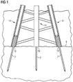
- a possible offshore foundation structure by which the invention can be realised is a jacket structure as it is shown in Figure 1 in highly schematic view.
- the jacket structure shown in this figure comprises three legs 11 each forming a tubular hollow foundation member.
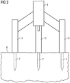
- Another possible offshore foundation structure by which the invention can be realised is the so called tripod structure that is schematically shown in Figure 2 .
- three legs 11 forming tubular hollow foundation members support a tube 9 carrying an installation like a wind turbine.
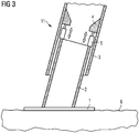
- FIG 3 shows a leg 11 of an inventive foundation structure, which could be either a tripod - or jacket type structure.
- the leg 11 is equipped with an open longitudinal end 12 which is placed on the seabed 6 such that the open longitudinal end 12 shows towards the seabed 6.
- the legs 11 are slightly tilted with respect to the vertical direction.
- Piles 7 may project through the open longitudinal ends 12 of the legs 11 into the seabed 6 to form anchors for the foundation structure.
- the interior of the longitudinal hollow foundation members 11 may be grouted, in particular the space between the piles 7 and the inside wall of the legs 11, in order to increase stability of the structure.
- piles as anchors securing the foundation structure in place can also be achieved by anchoring means other than piles or by means of gravitation foundations.
- Figure 3 shows the seabed end of a leg 11 of a wind turbine foundation structure (e.g. tripod or jacket).
- a wind turbine foundation structure e.g. tripod or jacket
- the legs 11 of the wind turbine foundation structure according to the first embodiment comprise(s) for a minimum configuration:
- the seabed plate tube 2 of the present embodiment is located inside the main tube 3.
- the main tube 3 and/or the seabed plate tube 2 further comprise(s) jack base means 4 which is prepared for holding the jack means 5 and/or providing support for the jack means 5 and which can withstand the loads applied to the base means 4 by e.g. the weight of the foundation structure through the jack means 5.
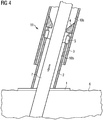
- Figure 4 shows the seabed end of a leg 11 of a wind turbine offshore foundation structure (e.g. tripod or jacket).
- the foundation structure is further supported in its position by one or more piles 7 penetrating the seabed 6.
- the piles 7 can be made of e.g. steel, concrete or reinforced concrete or a combination hereof.
- the piles 7 are established in the seabed 6 after the foundation structure is placed on the seabed such as through the main tube 3 and the seabed plate tube 2 as indicated by the arrow in the figure.
- the main tube 3 and/or the seabed plate tube 2 may be secured to the pile 7 by grouting the space 10b between the pile 7 and the seabed plate tube 2 and/or the space 10a between the pile 7 and the main tube 3.
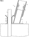
- FIG. 5 An offshore foundation which is not part of the invention as claimed in the appended claims is schematically illustrated in Figure 5 .
- Figure 5 shows the seabed end of a leg 11 of a wind turbine foundation structure (e.g. tripod or jacket).
- the seabed plate 1 further comprises a separate pile tube 8 which extends vertically or near vertically from the seabed plate 1 and which is prepared for receiving a pile 7.
- the piles 7 can be made of e.g. steel, concrete or reinforced concrete or a combination hereof.
- the piles 7 may be established in the seabed 6 before the foundation structure and the pile tubes 8 of the seabed plate 1 are placed over the piles.
- the piles 7 may be established in the seabed 6 after the foundation structure is placed on the seabed such as through the pile tube 8.
- the pile tube 8 may be secured to the pile 7 by grouting the space 10c between the pile 7 and the pile tube 8.
- the jack means 5 may be e.g. hydraulic operated, pneumatic operated or manually operated.
- the jack means 5 may be removable so that it can be removed after positioning and possible grouting, or the jack means 5 may be non-removable so that it stays installed after positioning and possible grouting.
- the invention can furthermore be advantageous in that the piles are established after the foundation structure has been positioned on the seabed. Thereby the piles do not need to be very accurately positioned on/in the seabed prior to positioning the foundation structure such as by a pre-fabricated and prepositioned pile-positioning template structure.
Landscapes
- Engineering & Computer Science (AREA)
- General Engineering & Computer Science (AREA)
- Civil Engineering (AREA)
- Structural Engineering (AREA)
- Life Sciences & Earth Sciences (AREA)
- General Life Sciences & Earth Sciences (AREA)
- Mining & Mineral Resources (AREA)
- Paleontology (AREA)
- Mechanical Engineering (AREA)
- Foundations (AREA)
- Wind Motors (AREA)
Claims (10)
- Structure de fondations en mer, en particulier structure de fondations d'éolienne, avec au moins une jambe (11) destinée à être positionnée sur le fond marin (6), dans laquelle l'au moins une jambe (11) comprend :- un tube principal (3) s'étendant le long d'un sens axial,- une plaque (1) de fond marin qui est située à l'extrémité de côté fond marin (6) du tube principal (3) et préparée pour maintenir la structure au moins temporairement sur le fond marin (6),caractérisée en ce que
l'au moins une jambe (11) comprend en outre :- un tube (2) de plaque de fond marin qui s'étend depuis ladite plaque (1) de fond marin jusque dans ledit tube principal (3) et est préparé pour être déplacé par rapport audit tube principal (3) dans le sens axial du tube principal (3),- un moyen (5) d'ajustement qui est apte à, et préparé pour, ajuster la longueur axiale de la jambe (11) où le moyen (5) d'ajustement est apte à, et préparé pour, ajuster la position axiale relative du tube principal (3) et du tube (2) de plaque de fond marin l'une par rapport à l'autre, et- un pilier (7) qui est adapté à être conduit à travers le tube (2) de plaque de fond marin et le tube principal (3) jusque dans le fond marin (6) et qui s'étend au moins partiellement à travers le tube (2) de plaque de fond marin et le tube principal (3). - Structure de fondations en mer selon la revendication 1, dans laquelle le moyen d'ajustement est un moyen (5) de vérin agissant entre ledit tube (2) de plaque de fond marin et ledit tube principal (3).
- Structure de fondations en mer selon la revendication 2, dans laquelle ledit tube de plaque de fond marin et/ou ledit tube principal comprennent/comprend un moyen (4) de base de vérin qui est préparé pour maintenir le moyen (5) de vérin et/ou pour offrir un support pour le moyen (5) de vérin.
- Structure de fondations en mer selon l'une quelconque des revendications 1 à 3, dans laquelle le moyen (5) d'ajustement est amovible.
- Fondations en mer, en particulier fondations d'éolienne, établies sur un fond marin comprenant une structure de fondations en mer selon l'une quelconque des revendications 1 à 4 qui repose sur le fond marin (6), dans lesquelles la longueur de la jambe (11) est ajustée de manière à niveler des variations de la hauteur du fond marin (6).
- Fondations en mer selon la revendication 5, dans lesquelles la longueur de la jambe (11) est ajustée par une position axiale relative ajustée du tube principal (3) et du tube (2) de plaque de fond marin l'une par rapport à l'autre.
- Fondations en mer selon la revendication 6, dans lesquelles il y a un espace entre le tube principal (3) et le tube (2) de plaque de fond marin et ledit espace est cimenté.
- Fondations en mer selon l'une quelconque des revendications 5 à 7, dans lesquelles l'au moins une jambe comprend un pilier (7) qui est conduit jusque dans le fond marin (6).
- Procédé d'établissement de fondations en mer, en particulier de fondations en mer d'éolienne, selon l'une quelconque des revendications 5 à 8 sur le fond marin, le procédé comprenant les étapes de positionnement d'une structure de fondations en mer selon l'une quelconque des revendications 1 à 4, d'ajustement de la structure de fondations en mer en utilisant le moyen (5) d'ajustement et l'étape d'ancrage de la structure de fondations en mer en conduisant des piliers (7) jusque dans le fond marin (6).
- Procédé selon la revendication 9, dans lequel la structure de fondations en mer est cimentée.
Priority Applications (1)
| Application Number | Priority Date | Filing Date | Title |
|---|---|---|---|
| EP10779288.9A EP2558648B1 (fr) | 2010-05-28 | 2010-11-05 | Structure de fondations en mer, fondations en mer et son procédé d'établissement |
Applications Claiming Priority (3)
| Application Number | Priority Date | Filing Date | Title |
|---|---|---|---|
| EP10164280 | 2010-05-28 | ||
| PCT/EP2010/066900 WO2011147481A2 (fr) | 2010-05-28 | 2010-11-05 | Structure de fondations en mer, fondations en mer et son procédé d'établissement |
| EP10779288.9A EP2558648B1 (fr) | 2010-05-28 | 2010-11-05 | Structure de fondations en mer, fondations en mer et son procédé d'établissement |
Publications (2)
| Publication Number | Publication Date |
|---|---|
| EP2558648A2 EP2558648A2 (fr) | 2013-02-20 |
| EP2558648B1 true EP2558648B1 (fr) | 2017-11-01 |
Family
ID=43571293
Family Applications (1)
| Application Number | Title | Priority Date | Filing Date |
|---|---|---|---|
| EP10779288.9A Not-in-force EP2558648B1 (fr) | 2010-05-28 | 2010-11-05 | Structure de fondations en mer, fondations en mer et son procédé d'établissement |
Country Status (2)
| Country | Link |
|---|---|
| EP (1) | EP2558648B1 (fr) |
| WO (1) | WO2011147481A2 (fr) |
Cited By (2)
| Publication number | Priority date | Publication date | Assignee | Title |
|---|---|---|---|---|
| WO2019074363A1 (fr) | 2017-10-10 | 2019-04-18 | Spt Equipment Bv | Système de fondation d'installation d'énergie éolienne en haute mer |
| NL2028088A (en) | 2020-04-29 | 2021-11-02 | Spt Equipment Bv | Concrete connector body for an offshore wind turbine. |
Families Citing this family (4)
| Publication number | Priority date | Publication date | Assignee | Title |
|---|---|---|---|---|
| EP2886851A1 (fr) * | 2013-12-18 | 2015-06-24 | Openhydro IP Limited | Système de turbine hydroélectrique amélioré |
| GB2536228A (en) * | 2015-03-09 | 2016-09-14 | Owec Tower As | Apparatus and methods for installing a substructure |
| CN106049494B (zh) * | 2016-07-15 | 2019-02-15 | 广州市维众建筑工程有限公司 | 分体式压桩机 |
| JP6927165B2 (ja) * | 2018-07-03 | 2021-08-25 | Jfeエンジニアリング株式会社 | 接合構造物、杭式構造物ならびに杭式構造物の撤去方法 |
Family Cites Families (9)
| Publication number | Priority date | Publication date | Assignee | Title |
|---|---|---|---|---|
| US5988949A (en) | 1996-01-11 | 1999-11-23 | Mcdermott Int Inc | Offshore jacket installation |
| DE10349109B4 (de) * | 2003-10-17 | 2008-02-07 | Aerodyn Engineering Gmbh | Gründung für eine Offshore-Windenergieanlage |
| DE102004042066B4 (de) | 2004-08-31 | 2006-12-14 | Bard Engineering Gmbh | Gründung für eine Offshore-Windkraftanlage |
| DE102005014868A1 (de) * | 2005-03-30 | 2006-10-05 | Repower Systems Ag | Offshore-Windenergieanlage mit rutschfesten Füßen |
| EP2067914A2 (fr) | 2007-12-04 | 2009-06-10 | WeserWind GmbH | Structure de grille d'une construction offshore, en particulier d'une éolienne offshore et son procédé de fabrication |
| GB0809521D0 (en) * | 2008-05-24 | 2008-07-02 | Marine Current Turbines Ltd | Installation of structures in water |
| CA2729047A1 (fr) * | 2008-06-23 | 2009-12-30 | Pluton Resources Ltd | Plateforme de forage |
| GB0902289D0 (en) * | 2009-02-12 | 2009-03-25 | Marine Current Turbines Ltd | Methods for installing pin-piled jacket type structures at sea |
| NO20093082A1 (no) * | 2009-10-01 | 2011-04-04 | Aker Jacket Technology As | Anordning, system og fremgangsmate for foring av peler i en havbunn |
-
2010
- 2010-11-05 WO PCT/EP2010/066900 patent/WO2011147481A2/fr active Application Filing
- 2010-11-05 EP EP10779288.9A patent/EP2558648B1/fr not_active Not-in-force
Non-Patent Citations (1)
| Title |
|---|
| None * |
Cited By (3)
| Publication number | Priority date | Publication date | Assignee | Title |
|---|---|---|---|---|
| WO2019074363A1 (fr) | 2017-10-10 | 2019-04-18 | Spt Equipment Bv | Système de fondation d'installation d'énergie éolienne en haute mer |
| NL2028088A (en) | 2020-04-29 | 2021-11-02 | Spt Equipment Bv | Concrete connector body for an offshore wind turbine. |
| WO2021221506A1 (fr) | 2020-04-29 | 2021-11-04 | Spt Equipment Bv | Fondation d'éolienne en mer |
Also Published As
| Publication number | Publication date |
|---|---|
| WO2011147481A2 (fr) | 2011-12-01 |
| EP2558648A2 (fr) | 2013-02-20 |
| WO2011147481A3 (fr) | 2012-10-18 |
Similar Documents
| Publication | Publication Date | Title |
|---|---|---|
| EP2558648B1 (fr) | Structure de fondations en mer, fondations en mer et son procédé d'établissement | |
| EP3039192B1 (fr) | Méthode pour installer une fondation offshore et modèle pour utilisation dans l'installation d'une fondation offshore | |
| JP5774158B2 (ja) | 水沈した支持構体の設置 | |
| DK1735506T3 (en) | Method of erecting a tower | |
| JP5278828B2 (ja) | ジャケットの据え付け方法 | |
| EP2836648B1 (fr) | Installation de structures offshores | |
| EP2574698B1 (fr) | Procédé et dispositif pour entraîner plusieurs piliers au fond de la mer | |
| DK2931977T3 (en) | PROCEDURE FOR ANCHORING A FOUNDATION STRUCTURE AND FOUNDATION STRUCTURE | |
| WO2011147484A1 (fr) | Dispositif pour aider à l'installation d'un pilier dans le fond de la mer, structure de fondation en mer et procédé d'établissement d'une fondation en mer | |
| DK2700750T3 (en) | Pile FOR OFFSHORE STRUCTURES AND METHOD FOR CONSTRUCTION OF A pile FOR OFFSHORE STRUCTURES | |
| EP2192238A1 (fr) | Fondation et procédé de formation de fondation pour tour d'éolienne | |
| US10590620B2 (en) | Method for constructing a foundation for a tower structure, and onshore tower structure | |
| US20210047797A1 (en) | Methods for retrofitting a wind turbine foundation and wind turbine foundations | |
| CN111197318B (zh) | 用于风力涡轮机的塔架的地基 | |
| JP6513470B2 (ja) | 設置用の基礎杭、太陽光パネルの設置用の基礎杭、基礎杭の設置方法および太陽光パネルの基礎杭の設置方法 | |
| WO2004057113A1 (fr) | Fondations d'une tour a contrainte transversale | |
| GB2369834A (en) | A method of making a foundation | |
| EP4087980B1 (fr) | Procédé d'installation d'un support pour supporter une structure de charge, telle qu'une éolienne, sur, par exemple, un fond marin | |
| EP2697455B1 (fr) | Procédé d'obtention d'un alignement vertical d'une tour | |
| EP2558647B1 (fr) | Structure de fondation en mer, fondation en mer utilisant une telle structure et procédé d'installation d'une fondation en mer | |
| US20220333328A1 (en) | System and method for levelling and gripping a jacket leg into a hollow foundation pile | |
| DK2677086T3 (en) | Method for anchoring a structure to a seabed and underwater foundation | |
| FI122698B (fi) | Menetelmä ja laitteisto tuulivoimalan asentamiseksi korkeaan perustusrakennelmaan | |
| KR101361842B1 (ko) | 경사파일 시공장치 및 이를 이용한 경사파일 시공방법 | |
| KR20230147778A (ko) | 유압실린더, 유압실린더를 구비하는 스태빙 시스템, 및 스태빙 시스템을 이용한 해양자켓구조물 설치방법 |
Legal Events
| Date | Code | Title | Description |
|---|---|---|---|
| PUAI | Public reference made under article 153(3) epc to a published international application that has entered the european phase |
Free format text: ORIGINAL CODE: 0009012 |
|
| 17P | Request for examination filed |
Effective date: 20121115 |
|
| AK | Designated contracting states |
Kind code of ref document: A2 Designated state(s): AL AT BE BG CH CY CZ DE DK EE ES FI FR GB GR HR HU IE IS IT LI LT LU LV MC MK MT NL NO PL PT RO RS SE SI SK SM TR |
|
| RAP1 | Party data changed (applicant data changed or rights of an application transferred) |
Owner name: SIEMENS AKTIENGESELLSCHAFT |
|
| DAX | Request for extension of the european patent (deleted) | ||
| 17Q | First examination report despatched |
Effective date: 20160808 |
|
| GRAP | Despatch of communication of intention to grant a patent |
Free format text: ORIGINAL CODE: EPIDOSNIGR1 |
|
| INTG | Intention to grant announced |
Effective date: 20170524 |
|
| RAP1 | Party data changed (applicant data changed or rights of an application transferred) |
Owner name: SIEMENS AKTIENGESELLSCHAFT |
|
| GRAS | Grant fee paid |
Free format text: ORIGINAL CODE: EPIDOSNIGR3 |
|
| GRAA | (expected) grant |
Free format text: ORIGINAL CODE: 0009210 |
|
| AK | Designated contracting states |
Kind code of ref document: B1 Designated state(s): AL AT BE BG CH CY CZ DE DK EE ES FI FR GB GR HR HU IE IS IT LI LT LU LV MC MK MT NL NO PL PT RO RS SE SI SK SM TR |
|
| REG | Reference to a national code |
Ref country code: GB Ref legal event code: FG4D |
|
| REG | Reference to a national code |
Ref country code: CH Ref legal event code: EP Ref country code: AT Ref legal event code: REF Ref document number: 942156 Country of ref document: AT Kind code of ref document: T Effective date: 20171115 |
|
| REG | Reference to a national code |
Ref country code: FR Ref legal event code: PLFP Year of fee payment: 8 |
|
| REG | Reference to a national code |
Ref country code: IE Ref legal event code: FG4D |
|
| REG | Reference to a national code |
Ref country code: DE Ref legal event code: R096 Ref document number: 602010046395 Country of ref document: DE |
|
| REG | Reference to a national code |
Ref country code: NL Ref legal event code: MP Effective date: 20171101 |
|
| REG | Reference to a national code |
Ref country code: LT Ref legal event code: MG4D |
|
| REG | Reference to a national code |
Ref country code: AT Ref legal event code: MK05 Ref document number: 942156 Country of ref document: AT Kind code of ref document: T Effective date: 20171101 |
|
| PG25 | Lapsed in a contracting state [announced via postgrant information from national office to epo] |
Ref country code: LT Free format text: LAPSE BECAUSE OF FAILURE TO SUBMIT A TRANSLATION OF THE DESCRIPTION OR TO PAY THE FEE WITHIN THE PRESCRIBED TIME-LIMIT Effective date: 20171101 Ref country code: NL Free format text: LAPSE BECAUSE OF FAILURE TO SUBMIT A TRANSLATION OF THE DESCRIPTION OR TO PAY THE FEE WITHIN THE PRESCRIBED TIME-LIMIT Effective date: 20171101 Ref country code: NO Free format text: LAPSE BECAUSE OF FAILURE TO SUBMIT A TRANSLATION OF THE DESCRIPTION OR TO PAY THE FEE WITHIN THE PRESCRIBED TIME-LIMIT Effective date: 20180201 Ref country code: ES Free format text: LAPSE BECAUSE OF FAILURE TO SUBMIT A TRANSLATION OF THE DESCRIPTION OR TO PAY THE FEE WITHIN THE PRESCRIBED TIME-LIMIT Effective date: 20171101 Ref country code: SE Free format text: LAPSE BECAUSE OF FAILURE TO SUBMIT A TRANSLATION OF THE DESCRIPTION OR TO PAY THE FEE WITHIN THE PRESCRIBED TIME-LIMIT Effective date: 20171101 Ref country code: FI Free format text: LAPSE BECAUSE OF FAILURE TO SUBMIT A TRANSLATION OF THE DESCRIPTION OR TO PAY THE FEE WITHIN THE PRESCRIBED TIME-LIMIT Effective date: 20171101 |
|
| PG25 | Lapsed in a contracting state [announced via postgrant information from national office to epo] |
Ref country code: AT Free format text: LAPSE BECAUSE OF FAILURE TO SUBMIT A TRANSLATION OF THE DESCRIPTION OR TO PAY THE FEE WITHIN THE PRESCRIBED TIME-LIMIT Effective date: 20171101 Ref country code: HR Free format text: LAPSE BECAUSE OF FAILURE TO SUBMIT A TRANSLATION OF THE DESCRIPTION OR TO PAY THE FEE WITHIN THE PRESCRIBED TIME-LIMIT Effective date: 20171101 Ref country code: BG Free format text: LAPSE BECAUSE OF FAILURE TO SUBMIT A TRANSLATION OF THE DESCRIPTION OR TO PAY THE FEE WITHIN THE PRESCRIBED TIME-LIMIT Effective date: 20180201 Ref country code: RS Free format text: LAPSE BECAUSE OF FAILURE TO SUBMIT A TRANSLATION OF THE DESCRIPTION OR TO PAY THE FEE WITHIN THE PRESCRIBED TIME-LIMIT Effective date: 20171101 Ref country code: GR Free format text: LAPSE BECAUSE OF FAILURE TO SUBMIT A TRANSLATION OF THE DESCRIPTION OR TO PAY THE FEE WITHIN THE PRESCRIBED TIME-LIMIT Effective date: 20180202 Ref country code: LV Free format text: LAPSE BECAUSE OF FAILURE TO SUBMIT A TRANSLATION OF THE DESCRIPTION OR TO PAY THE FEE WITHIN THE PRESCRIBED TIME-LIMIT Effective date: 20171101 Ref country code: IS Free format text: LAPSE BECAUSE OF FAILURE TO SUBMIT A TRANSLATION OF THE DESCRIPTION OR TO PAY THE FEE WITHIN THE PRESCRIBED TIME-LIMIT Effective date: 20180301 |
|
| PG25 | Lapsed in a contracting state [announced via postgrant information from national office to epo] |
Ref country code: LI Free format text: LAPSE BECAUSE OF NON-PAYMENT OF DUE FEES Effective date: 20171130 Ref country code: DK Free format text: LAPSE BECAUSE OF FAILURE TO SUBMIT A TRANSLATION OF THE DESCRIPTION OR TO PAY THE FEE WITHIN THE PRESCRIBED TIME-LIMIT Effective date: 20171101 Ref country code: SK Free format text: LAPSE BECAUSE OF FAILURE TO SUBMIT A TRANSLATION OF THE DESCRIPTION OR TO PAY THE FEE WITHIN THE PRESCRIBED TIME-LIMIT Effective date: 20171101 Ref country code: EE Free format text: LAPSE BECAUSE OF FAILURE TO SUBMIT A TRANSLATION OF THE DESCRIPTION OR TO PAY THE FEE WITHIN THE PRESCRIBED TIME-LIMIT Effective date: 20171101 Ref country code: CY Free format text: LAPSE BECAUSE OF FAILURE TO SUBMIT A TRANSLATION OF THE DESCRIPTION OR TO PAY THE FEE WITHIN THE PRESCRIBED TIME-LIMIT Effective date: 20171101 Ref country code: CH Free format text: LAPSE BECAUSE OF NON-PAYMENT OF DUE FEES Effective date: 20171130 Ref country code: CZ Free format text: LAPSE BECAUSE OF FAILURE TO SUBMIT A TRANSLATION OF THE DESCRIPTION OR TO PAY THE FEE WITHIN THE PRESCRIBED TIME-LIMIT Effective date: 20171101 |
|
| REG | Reference to a national code |
Ref country code: DE Ref legal event code: R097 Ref document number: 602010046395 Country of ref document: DE |
|
| PG25 | Lapsed in a contracting state [announced via postgrant information from national office to epo] |
Ref country code: IT Free format text: LAPSE BECAUSE OF FAILURE TO SUBMIT A TRANSLATION OF THE DESCRIPTION OR TO PAY THE FEE WITHIN THE PRESCRIBED TIME-LIMIT Effective date: 20171101 Ref country code: PL Free format text: LAPSE BECAUSE OF FAILURE TO SUBMIT A TRANSLATION OF THE DESCRIPTION OR TO PAY THE FEE WITHIN THE PRESCRIBED TIME-LIMIT Effective date: 20171101 Ref country code: SM Free format text: LAPSE BECAUSE OF FAILURE TO SUBMIT A TRANSLATION OF THE DESCRIPTION OR TO PAY THE FEE WITHIN THE PRESCRIBED TIME-LIMIT Effective date: 20171101 Ref country code: RO Free format text: LAPSE BECAUSE OF FAILURE TO SUBMIT A TRANSLATION OF THE DESCRIPTION OR TO PAY THE FEE WITHIN THE PRESCRIBED TIME-LIMIT Effective date: 20171101 Ref country code: LU Free format text: LAPSE BECAUSE OF NON-PAYMENT OF DUE FEES Effective date: 20171105 |
|
| REG | Reference to a national code |
Ref country code: BE Ref legal event code: MM Effective date: 20171130 |
|
| REG | Reference to a national code |
Ref country code: IE Ref legal event code: MM4A |
|
| PLBE | No opposition filed within time limit |
Free format text: ORIGINAL CODE: 0009261 |
|
| STAA | Information on the status of an ep patent application or granted ep patent |
Free format text: STATUS: NO OPPOSITION FILED WITHIN TIME LIMIT |
|
| PG25 | Lapsed in a contracting state [announced via postgrant information from national office to epo] |
Ref country code: MT Free format text: LAPSE BECAUSE OF NON-PAYMENT OF DUE FEES Effective date: 20171105 |
|
| 26N | No opposition filed |
Effective date: 20180802 |
|
| PG25 | Lapsed in a contracting state [announced via postgrant information from national office to epo] |
Ref country code: IE Free format text: LAPSE BECAUSE OF NON-PAYMENT OF DUE FEES Effective date: 20171105 |
|
| PG25 | Lapsed in a contracting state [announced via postgrant information from national office to epo] |
Ref country code: SI Free format text: LAPSE BECAUSE OF FAILURE TO SUBMIT A TRANSLATION OF THE DESCRIPTION OR TO PAY THE FEE WITHIN THE PRESCRIBED TIME-LIMIT Effective date: 20171101 Ref country code: BE Free format text: LAPSE BECAUSE OF NON-PAYMENT OF DUE FEES Effective date: 20171130 |
|
| PG25 | Lapsed in a contracting state [announced via postgrant information from national office to epo] |
Ref country code: MC Free format text: LAPSE BECAUSE OF FAILURE TO SUBMIT A TRANSLATION OF THE DESCRIPTION OR TO PAY THE FEE WITHIN THE PRESCRIBED TIME-LIMIT Effective date: 20171101 Ref country code: HU Free format text: LAPSE BECAUSE OF FAILURE TO SUBMIT A TRANSLATION OF THE DESCRIPTION OR TO PAY THE FEE WITHIN THE PRESCRIBED TIME-LIMIT; INVALID AB INITIO Effective date: 20101105 |
|
| REG | Reference to a national code |
Ref country code: DE Ref legal event code: R081 Ref document number: 602010046395 Country of ref document: DE Owner name: SIEMENS GAMESA RENEWABLE ENERGY A/S, DK Free format text: FORMER OWNER: SIEMENS AKTIENGESELLSCHAFT, 80333 MUENCHEN, DE |
|
| PG25 | Lapsed in a contracting state [announced via postgrant information from national office to epo] |
Ref country code: MK Free format text: LAPSE BECAUSE OF FAILURE TO SUBMIT A TRANSLATION OF THE DESCRIPTION OR TO PAY THE FEE WITHIN THE PRESCRIBED TIME-LIMIT Effective date: 20171101 |
|
| REG | Reference to a national code |
Ref country code: GB Ref legal event code: 732E Free format text: REGISTERED BETWEEN 20191128 AND 20191204 |
|
| PG25 | Lapsed in a contracting state [announced via postgrant information from national office to epo] |
Ref country code: TR Free format text: LAPSE BECAUSE OF FAILURE TO SUBMIT A TRANSLATION OF THE DESCRIPTION OR TO PAY THE FEE WITHIN THE PRESCRIBED TIME-LIMIT Effective date: 20171101 |
|
| PG25 | Lapsed in a contracting state [announced via postgrant information from national office to epo] |
Ref country code: PT Free format text: LAPSE BECAUSE OF FAILURE TO SUBMIT A TRANSLATION OF THE DESCRIPTION OR TO PAY THE FEE WITHIN THE PRESCRIBED TIME-LIMIT Effective date: 20171101 |
|
| PG25 | Lapsed in a contracting state [announced via postgrant information from national office to epo] |
Ref country code: AL Free format text: LAPSE BECAUSE OF FAILURE TO SUBMIT A TRANSLATION OF THE DESCRIPTION OR TO PAY THE FEE WITHIN THE PRESCRIBED TIME-LIMIT Effective date: 20171101 |
|
| PGFP | Annual fee paid to national office [announced via postgrant information from national office to epo] |
Ref country code: GB Payment date: 20201202 Year of fee payment: 11 Ref country code: FR Payment date: 20201112 Year of fee payment: 11 |
|
| PGFP | Annual fee paid to national office [announced via postgrant information from national office to epo] |
Ref country code: DE Payment date: 20210119 Year of fee payment: 11 |
|
| REG | Reference to a national code |
Ref country code: DE Ref legal event code: R119 Ref document number: 602010046395 Country of ref document: DE |
|
| GBPC | Gb: european patent ceased through non-payment of renewal fee |
Effective date: 20211105 |
|
| PG25 | Lapsed in a contracting state [announced via postgrant information from national office to epo] |
Ref country code: GB Free format text: LAPSE BECAUSE OF NON-PAYMENT OF DUE FEES Effective date: 20211105 Ref country code: DE Free format text: LAPSE BECAUSE OF NON-PAYMENT OF DUE FEES Effective date: 20220601 |
|
| PG25 | Lapsed in a contracting state [announced via postgrant information from national office to epo] |
Ref country code: FR Free format text: LAPSE BECAUSE OF NON-PAYMENT OF DUE FEES Effective date: 20211130 |