EP2557558A1 - Display device - Google Patents
Display device Download PDFInfo
- Publication number
- EP2557558A1 EP2557558A1 EP12178548A EP12178548A EP2557558A1 EP 2557558 A1 EP2557558 A1 EP 2557558A1 EP 12178548 A EP12178548 A EP 12178548A EP 12178548 A EP12178548 A EP 12178548A EP 2557558 A1 EP2557558 A1 EP 2557558A1
- Authority
- EP
- European Patent Office
- Prior art keywords
- display panel
- flexible display
- recognition pattern
- sensor
- display area
- Prior art date
- Legal status (The legal status is an assumption and is not a legal conclusion. Google has not performed a legal analysis and makes no representation as to the accuracy of the status listed.)
- Withdrawn
Links
Images


Classifications
-
- G—PHYSICS
- G09—EDUCATION; CRYPTOGRAPHY; DISPLAY; ADVERTISING; SEALS
- G09G—ARRANGEMENTS OR CIRCUITS FOR CONTROL OF INDICATING DEVICES USING STATIC MEANS TO PRESENT VARIABLE INFORMATION
- G09G3/00—Control arrangements or circuits, of interest only in connection with visual indicators other than cathode-ray tubes
- G09G3/20—Control arrangements or circuits, of interest only in connection with visual indicators other than cathode-ray tubes for presentation of an assembly of a number of characters, e.g. a page, by composing the assembly by combination of individual elements arranged in a matrix no fixed position being assigned to or needed to be assigned to the individual characters or partial characters
-
- G—PHYSICS
- G09—EDUCATION; CRYPTOGRAPHY; DISPLAY; ADVERTISING; SEALS
- G09F—DISPLAYING; ADVERTISING; SIGNS; LABELS OR NAME-PLATES; SEALS
- G09F9/00—Indicating arrangements for variable information in which the information is built-up on a support by selection or combination of individual elements
-
- G—PHYSICS
- G06—COMPUTING OR CALCULATING; COUNTING
- G06F—ELECTRIC DIGITAL DATA PROCESSING
- G06F1/00—Details not covered by groups G06F3/00 - G06F13/00 and G06F21/00
- G06F1/16—Constructional details or arrangements
- G06F1/1613—Constructional details or arrangements for portable computers
- G06F1/1633—Constructional details or arrangements of portable computers not specific to the type of enclosures covered by groups G06F1/1615 - G06F1/1626
- G06F1/1637—Details related to the display arrangement, including those related to the mounting of the display in the housing
- G06F1/1652—Details related to the display arrangement, including those related to the mounting of the display in the housing the display being flexible, e.g. mimicking a sheet of paper, or rollable
-
- G—PHYSICS
- G06—COMPUTING OR CALCULATING; COUNTING
- G06K—GRAPHICAL DATA READING; PRESENTATION OF DATA; RECORD CARRIERS; HANDLING RECORD CARRIERS
- G06K7/00—Methods or arrangements for sensing record carriers, e.g. for reading patterns
- G06K7/10—Methods or arrangements for sensing record carriers, e.g. for reading patterns by electromagnetic radiation, e.g. optical sensing; by corpuscular radiation
-
- G—PHYSICS
- G06—COMPUTING OR CALCULATING; COUNTING
- G06V—IMAGE OR VIDEO RECOGNITION OR UNDERSTANDING
- G06V30/00—Character recognition; Recognising digital ink; Document-oriented image-based pattern recognition
- G06V30/10—Character recognition
- G06V30/22—Character recognition characterised by the type of writing
- G06V30/224—Character recognition characterised by the type of writing of printed characters having additional code marks or containing code marks
-
- G—PHYSICS
- G09—EDUCATION; CRYPTOGRAPHY; DISPLAY; ADVERTISING; SEALS
- G09G—ARRANGEMENTS OR CIRCUITS FOR CONTROL OF INDICATING DEVICES USING STATIC MEANS TO PRESENT VARIABLE INFORMATION
- G09G3/00—Control arrangements or circuits, of interest only in connection with visual indicators other than cathode-ray tubes
- G09G3/03—Control arrangements or circuits, of interest only in connection with visual indicators other than cathode-ray tubes specially adapted for displays having non-planar surfaces, e.g. curved displays
- G09G3/035—Control arrangements or circuits, of interest only in connection with visual indicators other than cathode-ray tubes specially adapted for displays having non-planar surfaces, e.g. curved displays for flexible display surfaces
-
- G—PHYSICS
- G02—OPTICS
- G02F—OPTICAL DEVICES OR ARRANGEMENTS FOR THE CONTROL OF LIGHT BY MODIFICATION OF THE OPTICAL PROPERTIES OF THE MEDIA OF THE ELEMENTS INVOLVED THEREIN; NON-LINEAR OPTICS; FREQUENCY-CHANGING OF LIGHT; OPTICAL LOGIC ELEMENTS; OPTICAL ANALOGUE/DIGITAL CONVERTERS
- G02F1/00—Devices or arrangements for the control of the intensity, colour, phase, polarisation or direction of light arriving from an independent light source, e.g. switching, gating or modulating; Non-linear optics
- G02F1/01—Devices or arrangements for the control of the intensity, colour, phase, polarisation or direction of light arriving from an independent light source, e.g. switching, gating or modulating; Non-linear optics for the control of the intensity, phase, polarisation or colour
- G02F1/13—Devices or arrangements for the control of the intensity, colour, phase, polarisation or direction of light arriving from an independent light source, e.g. switching, gating or modulating; Non-linear optics for the control of the intensity, phase, polarisation or colour based on liquid crystals, e.g. single liquid crystal display cells
- G02F1/133—Constructional arrangements; Operation of liquid crystal cells; Circuit arrangements
- G02F1/1333—Constructional arrangements; Manufacturing methods
- G02F1/133305—Flexible substrates, e.g. plastics, organic film
-
- G—PHYSICS
- G09—EDUCATION; CRYPTOGRAPHY; DISPLAY; ADVERTISING; SEALS
- G09G—ARRANGEMENTS OR CIRCUITS FOR CONTROL OF INDICATING DEVICES USING STATIC MEANS TO PRESENT VARIABLE INFORMATION
- G09G2310/00—Command of the display device
- G09G2310/04—Partial updating of the display screen
Definitions
- the present invention relates generally to a display device. More particularly, the invention relates to a display device including a flexible display panel.
- a display device is a device for displaying an image, and flexible display devices have recently been more widely developed and implemented in various devices and applications.
- a conventional flexible display device is a device including a flexible display panel for displaying an image, and can be more portable because the size of the flexible display can be reduced by being folded or rolled.
- the invention sets out to provide a display device for displaying an image that has optimized or improved characteristics in view of the flexibility of a flexible display panel.
- One aspect of an embodiment of the present invention provides a display device including: a flexible display panel including a recognition pattern; a housing for holding the flexible display panel, wherein varying amounts of a display area of the flexible display panel are exposable to the outside to display an image; and a sensor in the housing for sensing an amount of the exposed display area corresponding to the recognition pattern.
- the display device may further include a controller connected with the sensor and the flexible display panel for displaying an image corresponding to the amount of the exposed display area sensed by the sensor.
- the flexible display panel may further include a non-display area neighboring the display area, wherein the recognition pattern may be in the non-display area.
- the flexible display panel may be configured to enter and exit the housing along a first direction, and the recognition pattern may be formed in the flexible display panel along the first direction.
- the recognition pattern may include first sub-patterns for absorbing light and second sub-patterns for reflecting light that are alternately arranged along the first direction, and the sensor may include a photo sensor including a light emitting portion and a light receiving portion neighboring each other.
- the recognition pattern may include a bar code and the sensor may be configured to read or recognize the bar code.
- the recognition pattern may include an ideogram and the sensor may be configured to read or recognize the ideogram.
- the recognition pattern may include first sub-patterns for transmitting light and second sub-patterns for blocking light, wherein the first sub-patterns and the second sub-patterns are alternately arranged along the first direction, and the sensor may include a photo sensor including a light emitting portion and a light receiving portion that are arranged on opposite sides of the recognition pattern.
- the housing may include a roll portion in the housing for rolling or storing the flexible display panel.
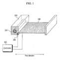
- FIG. 1 shows a display device according to a first embodiment of the invention
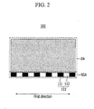
- FIG. 2 shows a flexible display panel of the display device according to the first embodiment
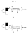
- FIG. 3 is provided to describe a sensing method of the display device according to the first embodiment
- FIG. 4 shows an image that the flexible display panel of the display device according to the first embodiment displays
- FIG. 5 shows a flexible display panel of a display device according to a second embodiment of the invention
- FIG. 6 shows a flexible display panel of a display device according to a third embodiment of the invention.
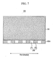
- FIG. 7 shows a flexible display panel of a display device according to a fourth embodiment of the invention.
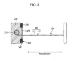
- FIG. 8 is provided to describe a sensing method of the display device according to the fourth embodiment.
- on implies being positioned above or below a target element, and does not necessarily imply being positioned on top based on, for example, a gravitational direction.
- the display device includes a flexible display panel 100, a housing 200, a sensor 300, and a controller 400.
- the flexible display panel 100 displays an image processed in the display device.
- the flexible display panel 100 may display an image such as a user interface (IU) or a graphic user interface (GUI).
- the flexible display panel 100 may include flexible substrates or films arranged opposite to each other, with interposing liquid crystals or organic light emitting diodes therebetween.
- the flexible display panel 100 may be a transparent or light transmissive type display panel, through which it is possible to view the outside or other side.
- a touch sensor provided as a touch film, a touch sheet, or a touch pad may be provided to sense touch operations.
- the flexible display panel 100 is connected with the controller 400, and displays an image using a signal transmitted from the controller 400.
- the flexible display panel 100 has flexibility, and may be put or retracted into or taken out of the housing 200.
- the flexible display panel 100 may be put into and taken out of the housing 200 along a first direction, and a display area of the flexible display panel 100 is variably exposed to the outside.
- FIG. 2 shows the flexible display panel of the display device according to the first embodiment.
- the flexible display panel 100 includes a display area DA for displaying an image, a non-display area NDA neighboring the display area DA, and a recognition pattern 110 disposed on the non-display area NDA.
- the display area DA and the non-display area NDA are disposed on a top or first side of the flexible display panel 100, but the present invention is not limited thereto.
- the display area DA may be disposed on the top side of the flexible display panel 100
- the non-display area NDA may be disposed on the bottom or second side of the flexible display panel 100.
- the recognition pattern 110 may be disposed on the bottom side or on the top side of the flexible display panel 100 according to different embodiments.
- the recognition pattern 110 of the display device according to this first embodiment is disposed in the non-display area NDA, but a recognition pattern of a display device according to another embodiment may instead be disposed in a display area DA where an image is displayed.
- the recognition pattern 110 may also be disposed between two neighboring substrates, and it may be formed simultaneously when a wire or a touch sensor of the flexible display panel 100 is formed.
- the recognition pattern 110 is arranged along a first direction along which the flexible display panel 100 is put into or taken out of the housing 200.
- the recognition pattern 110 includes first sub-patterns 111 and second sub-patterns 112 that are alternately arranged along the first direction.
- the first sub-pattern 111 has a black color for absorbing light and the second sub-pattern 112 has a white color for reflecting light.
- the housing 200 supports one end of the flexible display panel 100, and receives or discharges the flexible display panel 100, so that the display area of the flexible display panel 100 is variably exposed.
- the housing 200 includes a roll portion 210 around which the flexible display panel 100 can be rolled.
- the roll portion 210 is disposed in the housing 200 and supports one end of the flexible display panel 100.
- the roll portion 210 rolls the flexible display panel 100 clockwise or counterclockwise, to allow the housing 200 to receive or discharge the flexible display panel 100 along the first direction.
- the roll portion 210 is rotatable in a passive or active manner, and the flexible display panel 100 can be put into or taken out of the housing 200 along the first direction as the roll portion 210 rotates.
- the sensor 300 may also be disposed in the housing 200.
- FIG. 3 is provided for describing a sensing method of the display device according to the first embodiment.
- the sensor 300 is disposed in the housing 200, and may correspond to the recognition pattern 110 disposed in the non-display area NDA of the flexible display panel 100.
- the sensor 300 may sense an amount of display area of the flexible display panel 100 that is exposed to the outside as the flexible display panel 100 is discharged from the housing 200, by for example, detecting and recognizing the recognition pattern 110.
- the sensor 300 is a photo sensor including a first light emission portion 310 and a first light receiving portion 320 that are arranged to be adjacent to each other.
- the first light emission portion 310 emits light toward the recognition pattern 110, and the first light receiving portion 320 receives the light that is emitted from the first light emission portion 310 and then reflected by the recognition pattern 110.
- the sensor 300 senses an amount of the display area of the flexible display panel 100 that is exposed to the outside as the flexible display panel 100 is discharged from the housing 200, by recognizing the recognition pattern 110 using the first light emission portion 310 and the first light receiving portion 320. Particularly, as shown in FIG. 3(b) , when the flexible display panel 100 enters or exits the housing 200 along the first direction, light emitted from the first light emission portion 310 is reflected only by the second sub-pattern 112 of the recognition pattern 110 and then recognized by the first light receiving portion 320.
- the senor 300 can count a number of second sub-patterns 112 recognized by the first light receiving portion 320, to sense the amount of the display area of the flexible display panel 100 exposed to the outside, as the flexible display panel 100 is discharged from the housing 200 along the first direction.
- a signal related to the exposed display area of the flexible display panel 100, and sensed by the sensor 300, may be transmitted to the controller 400.
- FIG. 4 shows an image displayed by the flexible display panel of the display device according to the first embodiment of the invention.
- the controller 400 is connected with the sensor 300 and the flexible display panel 100, and adjusts and displays an image corresponding to an amount of exposed display area of the flexible display panel 100 sensed by the sensor 300 through the flexible display panel 100.
- the sensor 300 senses the first display area DS1 and transmits a signal adjusted for the display area DS1 to the controller 400.
- the controller 400 receives the signal and displays an image having a first size corresponding to the first display area DS1 of the flexible display panel 100.
- the senor 300 senses the second display area DS2 and transmits a signal adjusted for the second display area DS2 to the controller 400.
- the controller 400 receives the signal and displays an image having a second size corresponding to the second display area DS2 of the flexible display panel 100.
- the sensor 300 senses the third display area DS3 and transmits a signal adjusted for the third display area DS3 to the controller 400.
- the controller 400 receives the signal and displays an image having a third size corresponding to the third display area DS3 of the flexible display panel 100.
- the sensor 300 recognizes the recognition pattern 110 formed in the flexible display panel 100 to sense the amount of the display area of the flexible display panel 100 exposed to the outside, and an image corresponding to the exposed display area is displayed on or through the flexible display panel 100, so that the image can be optimized for characteristics of flexibility of the flexible display panel 100 based on, for example, an exposed display area.
- the display device recognizes the recognition pattern 110 formed in the flexible display pattern 100 using the sensor 300 to sense an amount of the display area of the flexible display panel 100 exposed to the outside as the flexible display panel 100 is discharged from the housing 200, and as such, the amount of display area can be accurately sensed even though the exposed portion is non-linearly twisted.
- the display device senses the display area of the flexible display panel 100 exposed to the outside using the sensor 300, which recognizes the recognition pattern 110 when the flexible display panel 100 is put into or taken out of the housing 200 in real time, rather than sensing the entire area of the flexible display panel 100 after the flexible display panel 100 is taken out of the housing 200.
- the exposed portion of the flexible display panel 100 is non-linearly twisted due to the characteristics of flexibility, an image having a size corresponding to the exposed display area of the flexible display panel 100 can be displayed by accurately sensing the exposed display area in such a manner.
- the display device senses the exposed display area of the flexible display panel 100 by recognizing the recognition pattern 110 formed in the flexible display panel 100 in real time in the above manner, rather than indirectly sensing the display area of the flexible display panel 100 by, for example, counting a number of rotations of the roll portion 210 or sensing the display area of the flexible display panel 100 after it is rolled out using a distance measurement means, such as using infrared rays or ultrasonic waves. Accordingly, an image having an accurate size that corresponds to the variable display area of the flexible display panel 100 is variably displayed by the flexible display panel 100. This may act, for example, as a factor for improving satisfaction of a user of the display device.
- a display device according to a second embodiment of the invention will be described with reference to FIG. 5 .
- FIG. 5 shows a flexible display panel of the display device according to the second embodiment.
- a flexible display panel 102 of the display device includes a display area DA for displaying an image, a non-display area NDA neighboring the display area DA, and a recognition pattern 120 in the non-display area NDA.
- the recognition pattern 120 may be arranged on a top or a bottom side of the flexible display panel 102, or may be between two neighboring substrates, and the recognition pattern 120 may be formed substantially simultaneously as when a wire or a touch sensor of the flexible display panel 102 is formed.
- the recognition pattern 120 is arranged along a first direction along which the flexible display panel 102 is put or retracted into or taken out of a housing 200.
- the recognition pattern 120 has a shape of, for example, a bar code arranged along the first direction.
- the sensor 300 senses an amount of display area of the flexible display panel 102 exposed to the outside as the flexible display panel 102 is discharged from the housing 200 by recognizing specific portions of the bar code of the recognition pattern 120.
- the sensor 300 scans the bar code of the recognition pattern 120 to sense the amount of currently exposed display area according to the recognition pattern 120.
- the recognition pattern 120 has the shape of a bar code
- the sensor 300 scans the bar code of the recognition pattern 120 to sense an amount of the currently exposed display area of the flexible display panel 102, to thereby display an image corresponding to the amount of exposed display area on the flexible display panel 102. Therefore, the display device according to the second embodiment can also provide an image optimized for characteristics of flexibility of the flexible display panel 102 based on, for example, an exposed display area.
- FIG. 6 shows a flexible display panel of the display device according to the third embodiment of the invention.
- a flexible display panel 103 of the display device includes a display area DA, a non-display area NDA neighboring the display area DA, and a recognition pattern 130 in the non-display area NDA.
- the recognition pattern 130 may be arranged on an upper or a bottom side of the flexible display panel 103, or may be between two neighboring substrates, and may be formed substantially simultaneously as when a wire or touch sensor of the flexible display panel 103 is formed.
- the recognition pattern 130 is arranged along a first direction along which the flexible display panel 103 is put or retracted into or taken out of the housing 200.
- the recognition pattern 130 has a shape (e.g., a predetermined shape) of an ideogram along the first direction.
- the sensor 300 senses an amount of display area of the flexible display panel 103 exposed to the outside as the flexible display panel 103 is discharged from the housing 200 by recognizing the ideogram of the recognition pattern 130.
- the sensor 300 scans the ideogram of the recognition pattern 130 to sense the amount of currently exposed display area of the flexible display panel 103.
- the predetermined ideogram of the recognition pattern 130 is represented by Arabic numerals, and when the sensor 300 scans Arabic numeral "5", the display area of the flexible display panel 103 exposed to the outside corresponds to a fifth step, and the flexible display panel 103 may display an image having a size corresponding to the fifth step.
- the recognition pattern 130 includes an ideogram
- the sensor 300 scans the ideogram of the recognition pattern 130 to sense an amount of the currently exposed display area of the flexible display panel 103, and thus an image corresponding to the currently exposed display area can be displayed on the flexible display panel 103.
- the display device can display an image optimized for characteristics of flexibility of the flexible display panel 103 based on, for example, an exposed display area.
- FIG. 7 and FIG. 8 a display device according to a fourth embodiment of the invention will be described with reference to FIG. 7 and FIG. 8 .
- FIG. 7 shows a flexible display panel of the display device according to the fourth embodiment.
- a flexible display panel 104 includes a display area DA for displaying an image, a non-display area NDA neighboring the display area DA, and a recognition pattern 140 in the non-display area NDA.
- the recognition pattern 140 may be arranged on an upper or a bottom side of the flexible display panel 104, or may be between two neighboring substrates, and the recognition pattern 140 may be formed substantially simultaneously as when a wire or touch sensor of the flexible display panel 104 is formed, or may be formed in an additional window that can protect the flexible display panel 104.
- the recognition pattern 140 is arranged along a first direction along which the flexible display panel 104 is put or retracted into or taken out of a housing 200.
- the recognition pattern 140 includes third sub-patterns 141 and fourth sub-patterns 142 alternately arranged along the first direction.
- the third sub-pattern 141 may be made of a transparent material that transmits light or may be a hole, and the fourth sub-pattern 142 may be made of an opaque material that blocks light.
- FIG. 8 is provided for description of a sensing method of the display device according to this fourth embodiment.
- a sensor 304 is positioned in the housing 200 corresponding to the recognition pattern 140 in the non-display area NDA.
- the sensor 304 senses an amount of display area of the flexible display panel 104 exposed to the outside as the flexible display panel 104 is discharged from the housing 200.
- the sensor 304 may be a photo sensor including a second light emitting portion 330 and a second light receiving portion 340 that are arranged opposite to each other, with the recognition pattern 140 interposed therebetween.
- the second light emitting portion 330 emits light toward the recognition pattern 140, and the second light receiving portion 340 receives light that is emitted from the second light emitting portion 330 and that passes through the recognition pattern 140.
- the sensor 304 recognizes the recognition pattern 140 using the second light emitting portion 330 and the second light receiving portion 340 to sense an amount of the display area of the flexible display panel 104 exposed to the outside as the flexible display panel 104 is discharged from the housing 200. Particularly, when the flexible display panel 104 is discharged from the housing 200 along the first direction, light emitted from the second light emitting portion 330 only passes through the third sub-patterns 141 of the recognition pattern 140, to then be recognized by the second light receiving portion 340. Therefore, the sensor 304 counts the number of third sub-patterns 141 recognized by the second light receiving portion 340, to sense and determine an amount of the display area exposed to the outside as the flexible display panel 104 is discharged from the housing 200. A signal related to the amount of exposed display area of the flexible display panel 104, sensed by the sensor 304, may be transmitted to a controller 400.
- the display device 304 senses the amount of display area of the flexible display panel 104 exposed to the outside as the flexible display panel 104 is put into or taken out of the housing 200, by recognizing the recognition pattern 140 in the flexible display panel 104 using the sensor 140.
- the flexible display panel 104 can then display an image corresponding to the amount of exposed display area. Accordingly, the image displayed by the flexible display panel 104 can be optimized for characteristics of flexibility of the flexible display panel 104 based on, for example, an exposed display area.
Landscapes
- Engineering & Computer Science (AREA)
- Theoretical Computer Science (AREA)
- Physics & Mathematics (AREA)
- General Physics & Mathematics (AREA)
- Computer Hardware Design (AREA)
- General Engineering & Computer Science (AREA)
- Human Computer Interaction (AREA)
- Computer Vision & Pattern Recognition (AREA)
- Devices For Indicating Variable Information By Combining Individual Elements (AREA)
- Multimedia (AREA)
- Artificial Intelligence (AREA)
- Toxicology (AREA)
- General Health & Medical Sciences (AREA)
- Electromagnetism (AREA)
- Health & Medical Sciences (AREA)
- Electroluminescent Light Sources (AREA)
- Liquid Crystal (AREA)
Abstract
Description
- The present invention relates generally to a display device. More particularly, the invention relates to a display device including a flexible display panel.
- A display device is a device for displaying an image, and flexible display devices have recently been more widely developed and implemented in various devices and applications.
- A conventional flexible display device is a device including a flexible display panel for displaying an image, and can be more portable because the size of the flexible display can be reduced by being folded or rolled.
- The above information disclosed in this Background section is only for enhancement of understanding of the background of the described technology, and therefore, may contain information that does not form the prior art that is already known in this country to a person of ordinary skill in the art.
- The invention sets out to provide a display device for displaying an image that has optimized or improved characteristics in view of the flexibility of a flexible display panel.
- One aspect of an embodiment of the present invention provides a display device including: a flexible display panel including a recognition pattern; a housing for holding the flexible display panel, wherein varying amounts of a display area of the flexible display panel are exposable to the outside to display an image; and a sensor in the housing for sensing an amount of the exposed display area corresponding to the recognition pattern.
- The display device may further include a controller connected with the sensor and the flexible display panel for displaying an image corresponding to the amount of the exposed display area sensed by the sensor.
- The flexible display panel may further include a non-display area neighboring the display area, wherein the recognition pattern may be in the non-display area.
- The flexible display panel may be configured to enter and exit the housing along a first direction, and the recognition pattern may be formed in the flexible display panel along the first direction.
- The recognition pattern may include first sub-patterns for absorbing light and second sub-patterns for reflecting light that are alternately arranged along the first direction, and the sensor may include a photo sensor including a light emitting portion and a light receiving portion neighboring each other.
- The recognition pattern may include a bar code and the sensor may be configured to read or recognize the bar code.
- The recognition pattern may include an ideogram and the sensor may be configured to read or recognize the ideogram.
- The recognition pattern may include first sub-patterns for transmitting light and second sub-patterns for blocking light, wherein the first sub-patterns and the second sub-patterns are alternately arranged along the first direction, and the sensor may include a photo sensor including a light emitting portion and a light receiving portion that are arranged on opposite sides of the recognition pattern.
- The housing may include a roll portion in the housing for rolling or storing the flexible display panel.
- At least some of the above and other features of the invention are set out in the claims.
-
FIG. 1 shows a display device according to a first embodiment of the invention; -
FIG. 2 shows a flexible display panel of the display device according to the first embodiment; -
FIG. 3 is provided to describe a sensing method of the display device according to the first embodiment; -
FIG. 4 shows an image that the flexible display panel of the display device according to the first embodiment displays; -
FIG. 5 shows a flexible display panel of a display device according to a second embodiment of the invention; -
FIG. 6 shows a flexible display panel of a display device according to a third embodiment of the invention; -
FIG. 7 shows a flexible display panel of a display device according to a fourth embodiment of the invention; and -
FIG. 8 is provided to describe a sensing method of the display device according to the fourth embodiment. - The present invention will be described more fully hereinafter with reference to the accompanying drawings, in which embodiments of the invention are shown. As those skilled in the art will recognize, the described embodiments may be modified in various different ways without departing from the scope of the present invention.
- In order to more clearly describe the embodiments, parts that are not related to the description thereof will be omitted. In addition, like reference numerals designate like elements throughout the specification.
- Elements having the same or similar structures throughout the embodiments are denoted by the same reference numerals and are described in a first embodiment. In subsequent embodiments, only the elements other than the same or similar elements from previous embodiments will be described in greater detail.
- In addition, the size and thickness of each component shown in the drawings are arbitrarily shown for understanding and ease of description, but the present invention is not limited thereto.
- In the drawings, the thickness of layers, films, panels, regions, etc., are exaggerated for clarity. In addition, in the drawings, for understanding and ease of description, the thicknesses of some layers and areas are exaggerated. It will also be understood that when an element is referred to as being "on" another element, it can be directly on the other element, or one or more intervening elements may also be present.
- In addition, throughout the specification, "on" implies being positioned above or below a target element, and does not necessarily imply being positioned on top based on, for example, a gravitational direction.
- Hereinafter, a display device according to a first embodiment of the invention will be described with reference to
FIG. 1 to FIG. 4 . - As shown in
FIG. 1 , the display device according to the first embodiment includes aflexible display panel 100, ahousing 200, asensor 300, and acontroller 400. - The
flexible display panel 100 displays an image processed in the display device. For example, if the display device is provided as a portable terminal such as a mobile phone, theflexible display panel 100 may display an image such as a user interface (IU) or a graphic user interface (GUI). Theflexible display panel 100 may include flexible substrates or films arranged opposite to each other, with interposing liquid crystals or organic light emitting diodes therebetween. Theflexible display panel 100 may be a transparent or light transmissive type display panel, through which it is possible to view the outside or other side. On a top side of theflexible display panel 100, a touch sensor provided as a touch film, a touch sheet, or a touch pad may be provided to sense touch operations. Theflexible display panel 100 is connected with thecontroller 400, and displays an image using a signal transmitted from thecontroller 400. Theflexible display panel 100 has flexibility, and may be put or retracted into or taken out of thehousing 200. Theflexible display panel 100 may be put into and taken out of thehousing 200 along a first direction, and a display area of theflexible display panel 100 is variably exposed to the outside. -
FIG. 2 shows the flexible display panel of the display device according to the first embodiment. - As shown in
FIG. 2 , theflexible display panel 100 includes a display area DA for displaying an image, a non-display area NDA neighboring the display area DA, and arecognition pattern 110 disposed on the non-display area NDA. - In the display device according to this first embodiment, the display area DA and the non-display area NDA are disposed on a top or first side of the
flexible display panel 100, but the present invention is not limited thereto. For example, the display area DA may be disposed on the top side of theflexible display panel 100, while the non-display area NDA may be disposed on the bottom or second side of theflexible display panel 100. In other words, when an image is displayed on the top side of theflexible display panel 100, therecognition pattern 110 may be disposed on the bottom side or on the top side of theflexible display panel 100 according to different embodiments. - The
recognition pattern 110 of the display device according to this first embodiment is disposed in the non-display area NDA, but a recognition pattern of a display device according to another embodiment may instead be disposed in a display area DA where an image is displayed. - The
recognition pattern 110 may also be disposed between two neighboring substrates, and it may be formed simultaneously when a wire or a touch sensor of theflexible display panel 100 is formed. Therecognition pattern 110 is arranged along a first direction along which theflexible display panel 100 is put into or taken out of thehousing 200. Therecognition pattern 110 includesfirst sub-patterns 111 andsecond sub-patterns 112 that are alternately arranged along the first direction. Thefirst sub-pattern 111 has a black color for absorbing light and thesecond sub-pattern 112 has a white color for reflecting light. - Referring back to
FIG. 1 , thehousing 200 supports one end of theflexible display panel 100, and receives or discharges theflexible display panel 100, so that the display area of theflexible display panel 100 is variably exposed. Thehousing 200 includes aroll portion 210 around which theflexible display panel 100 can be rolled. Theroll portion 210 is disposed in thehousing 200 and supports one end of theflexible display panel 100. Theroll portion 210 rolls theflexible display panel 100 clockwise or counterclockwise, to allow thehousing 200 to receive or discharge theflexible display panel 100 along the first direction. Theroll portion 210 is rotatable in a passive or active manner, and theflexible display panel 100 can be put into or taken out of thehousing 200 along the first direction as theroll portion 210 rotates. Thesensor 300 may also be disposed in thehousing 200. -
FIG. 3 is provided for describing a sensing method of the display device according to the first embodiment. - As shown in
FIG. 3 , thesensor 300 is disposed in thehousing 200, and may correspond to therecognition pattern 110 disposed in the non-display area NDA of theflexible display panel 100. Thesensor 300 may sense an amount of display area of theflexible display panel 100 that is exposed to the outside as theflexible display panel 100 is discharged from thehousing 200, by for example, detecting and recognizing therecognition pattern 110. - The
sensor 300 is a photo sensor including a firstlight emission portion 310 and a firstlight receiving portion 320 that are arranged to be adjacent to each other. - The first
light emission portion 310 emits light toward therecognition pattern 110, and the firstlight receiving portion 320 receives the light that is emitted from the firstlight emission portion 310 and then reflected by therecognition pattern 110. - The
sensor 300 senses an amount of the display area of theflexible display panel 100 that is exposed to the outside as theflexible display panel 100 is discharged from thehousing 200, by recognizing therecognition pattern 110 using the firstlight emission portion 310 and the firstlight receiving portion 320. Particularly, as shown inFIG. 3(b) , when theflexible display panel 100 enters or exits thehousing 200 along the first direction, light emitted from the firstlight emission portion 310 is reflected only by thesecond sub-pattern 112 of therecognition pattern 110 and then recognized by the firstlight receiving portion 320. Accordingly, thesensor 300 can count a number ofsecond sub-patterns 112 recognized by the firstlight receiving portion 320, to sense the amount of the display area of theflexible display panel 100 exposed to the outside, as theflexible display panel 100 is discharged from thehousing 200 along the first direction. A signal related to the exposed display area of theflexible display panel 100, and sensed by thesensor 300, may be transmitted to thecontroller 400. -
FIG. 4 shows an image displayed by the flexible display panel of the display device according to the first embodiment of the invention. - As shown in
FIG. 4 , thecontroller 400 is connected with thesensor 300 and theflexible display panel 100, and adjusts and displays an image corresponding to an amount of exposed display area of theflexible display panel 100 sensed by thesensor 300 through theflexible display panel 100. - Particularly, as shown in
FIG. 4(a) , when a first length of theflexible display panel 100 is discharged from thehousing 200 along the first direction, where a first display area DS1 is exposed, thesensor 300 senses the first display area DS1 and transmits a signal adjusted for the display area DS1 to thecontroller 400. Thecontroller 400 receives the signal and displays an image having a first size corresponding to the first display area DS1 of theflexible display panel 100. - In addition, as shown in
FIG. 4(b) , when a second length of theflexible display panel 100 is discharged from thehousing 200 along the first direction, where a second display area DS2 that is larger than the first display area DS1 is exposed, thesensor 300 senses the second display area DS2 and transmits a signal adjusted for the second display area DS2 to thecontroller 400. Thecontroller 400 receives the signal and displays an image having a second size corresponding to the second display area DS2 of theflexible display panel 100. - Further, as shown in
FIG. 4(c) , when a third length of theflexible display panel 100 is discharged from thehousing 200 along the first direction, where a third display area DS3 that is larger than the second display area DS2 is exposed, thesensor 300 senses the third display area DS3 and transmits a signal adjusted for the third display area DS3 to thecontroller 400. Thecontroller 400 receives the signal and displays an image having a third size corresponding to the third display area DS3 of theflexible display panel 100. - As described above, in the display device according to this first embodiment of the invention, the
sensor 300 recognizes therecognition pattern 110 formed in theflexible display panel 100 to sense the amount of the display area of theflexible display panel 100 exposed to the outside, and an image corresponding to the exposed display area is displayed on or through theflexible display panel 100, so that the image can be optimized for characteristics of flexibility of theflexible display panel 100 based on, for example, an exposed display area. - In particular, the display device according to this first embodiment recognizes the
recognition pattern 110 formed in theflexible display pattern 100 using thesensor 300 to sense an amount of the display area of theflexible display panel 100 exposed to the outside as theflexible display panel 100 is discharged from thehousing 200, and as such, the amount of display area can be accurately sensed even though the exposed portion is non-linearly twisted. - That is, the display device according to the first embodiment senses the display area of the
flexible display panel 100 exposed to the outside using thesensor 300, which recognizes therecognition pattern 110 when theflexible display panel 100 is put into or taken out of thehousing 200 in real time, rather than sensing the entire area of theflexible display panel 100 after theflexible display panel 100 is taken out of thehousing 200. Thus, even though the exposed portion of theflexible display panel 100 is non-linearly twisted due to the characteristics of flexibility, an image having a size corresponding to the exposed display area of theflexible display panel 100 can be displayed by accurately sensing the exposed display area in such a manner. - Further, the display device according to this first embodiment of the invention senses the exposed display area of the
flexible display panel 100 by recognizing therecognition pattern 110 formed in theflexible display panel 100 in real time in the above manner, rather than indirectly sensing the display area of theflexible display panel 100 by, for example, counting a number of rotations of theroll portion 210 or sensing the display area of theflexible display panel 100 after it is rolled out using a distance measurement means, such as using infrared rays or ultrasonic waves. Accordingly, an image having an accurate size that corresponds to the variable display area of theflexible display panel 100 is variably displayed by theflexible display panel 100. This may act, for example, as a factor for improving satisfaction of a user of the display device. - A display device according to a second embodiment of the invention will be described with reference to
FIG. 5 . -
FIG. 5 shows a flexible display panel of the display device according to the second embodiment. - As shown in
FIG. 5 , aflexible display panel 102 of the display device according to the second embodiment includes a display area DA for displaying an image, a non-display area NDA neighboring the display area DA, and arecognition pattern 120 in the non-display area NDA. - The
recognition pattern 120 may be arranged on a top or a bottom side of theflexible display panel 102, or may be between two neighboring substrates, and therecognition pattern 120 may be formed substantially simultaneously as when a wire or a touch sensor of theflexible display panel 102 is formed. Therecognition pattern 120 is arranged along a first direction along which theflexible display panel 102 is put or retracted into or taken out of ahousing 200. Therecognition pattern 120 has a shape of, for example, a bar code arranged along the first direction. - The
sensor 300 senses an amount of display area of theflexible display panel 102 exposed to the outside as theflexible display panel 102 is discharged from thehousing 200 by recognizing specific portions of the bar code of therecognition pattern 120. - Particularly, when the
flexible display panel 102 is discharged from thehousing 200 along the first direction, thesensor 300 scans the bar code of therecognition pattern 120 to sense the amount of currently exposed display area according to therecognition pattern 120. - As described above, the
recognition pattern 120 has the shape of a bar code, and thesensor 300 scans the bar code of therecognition pattern 120 to sense an amount of the currently exposed display area of theflexible display panel 102, to thereby display an image corresponding to the amount of exposed display area on theflexible display panel 102. Therefore, the display device according to the second embodiment can also provide an image optimized for characteristics of flexibility of theflexible display panel 102 based on, for example, an exposed display area. - Hereinafter, a display device according to a third embodiment of the invention will be described with reference to
FIG. 6 . -
FIG. 6 shows a flexible display panel of the display device according to the third embodiment of the invention. - As shown in
FIG. 6 , aflexible display panel 103 of the display device according to the third embodiment includes a display area DA, a non-display area NDA neighboring the display area DA, and arecognition pattern 130 in the non-display area NDA. - The
recognition pattern 130 may be arranged on an upper or a bottom side of theflexible display panel 103, or may be between two neighboring substrates, and may be formed substantially simultaneously as when a wire or touch sensor of theflexible display panel 103 is formed. Therecognition pattern 130 is arranged along a first direction along which theflexible display panel 103 is put or retracted into or taken out of thehousing 200. Therecognition pattern 130 has a shape (e.g., a predetermined shape) of an ideogram along the first direction. - The
sensor 300 senses an amount of display area of theflexible display panel 103 exposed to the outside as theflexible display panel 103 is discharged from thehousing 200 by recognizing the ideogram of therecognition pattern 130. - Particularly, when the
flexible display panel 103 is put into or discharged from thehousing 200 along the first direction, thesensor 300 scans the ideogram of therecognition pattern 130 to sense the amount of currently exposed display area of theflexible display panel 103. For example, if the predetermined ideogram of therecognition pattern 130 is represented by Arabic numerals, and when thesensor 300 scans Arabic numeral "5", the display area of theflexible display panel 103 exposed to the outside corresponds to a fifth step, and theflexible display panel 103 may display an image having a size corresponding to the fifth step. - As described above, according to this third embodiment of the invention, the
recognition pattern 130 includes an ideogram, and thesensor 300 scans the ideogram of therecognition pattern 130 to sense an amount of the currently exposed display area of theflexible display panel 103, and thus an image corresponding to the currently exposed display area can be displayed on theflexible display panel 103. Accordingly, the display device can display an image optimized for characteristics of flexibility of theflexible display panel 103 based on, for example, an exposed display area. - Hereinafter, a display device according to a fourth embodiment of the invention will be described with reference to
FIG. 7 andFIG. 8 . -
FIG. 7 shows a flexible display panel of the display device according to the fourth embodiment. - As shown in
FIG. 7 , aflexible display panel 104 includes a display area DA for displaying an image, a non-display area NDA neighboring the display area DA, and arecognition pattern 140 in the non-display area NDA. - The
recognition pattern 140 may be arranged on an upper or a bottom side of theflexible display panel 104, or may be between two neighboring substrates, and therecognition pattern 140 may be formed substantially simultaneously as when a wire or touch sensor of theflexible display panel 104 is formed, or may be formed in an additional window that can protect theflexible display panel 104. Therecognition pattern 140 is arranged along a first direction along which theflexible display panel 104 is put or retracted into or taken out of ahousing 200. Therecognition pattern 140 includesthird sub-patterns 141 andfourth sub-patterns 142 alternately arranged along the first direction. The third sub-pattern 141 may be made of a transparent material that transmits light or may be a hole, and thefourth sub-pattern 142 may be made of an opaque material that blocks light. -
FIG. 8 is provided for description of a sensing method of the display device according to this fourth embodiment. - As shown in
FIG. 8 , asensor 304 is positioned in thehousing 200 corresponding to therecognition pattern 140 in the non-display area NDA. Thesensor 304 senses an amount of display area of theflexible display panel 104 exposed to the outside as theflexible display panel 104 is discharged from thehousing 200. - The
sensor 304 may be a photo sensor including a secondlight emitting portion 330 and a secondlight receiving portion 340 that are arranged opposite to each other, with therecognition pattern 140 interposed therebetween. - The second
light emitting portion 330 emits light toward therecognition pattern 140, and the secondlight receiving portion 340 receives light that is emitted from the secondlight emitting portion 330 and that passes through therecognition pattern 140. - The
sensor 304 recognizes therecognition pattern 140 using the secondlight emitting portion 330 and the secondlight receiving portion 340 to sense an amount of the display area of theflexible display panel 104 exposed to the outside as theflexible display panel 104 is discharged from thehousing 200. Particularly, when theflexible display panel 104 is discharged from thehousing 200 along the first direction, light emitted from the secondlight emitting portion 330 only passes through thethird sub-patterns 141 of therecognition pattern 140, to then be recognized by the secondlight receiving portion 340. Therefore, thesensor 304 counts the number ofthird sub-patterns 141 recognized by the secondlight receiving portion 340, to sense and determine an amount of the display area exposed to the outside as theflexible display panel 104 is discharged from thehousing 200. A signal related to the amount of exposed display area of theflexible display panel 104, sensed by thesensor 304, may be transmitted to acontroller 400. - As described, the
display device 304 according to this fourth embodiment of the invention senses the amount of display area of theflexible display panel 104 exposed to the outside as theflexible display panel 104 is put into or taken out of thehousing 200, by recognizing therecognition pattern 140 in theflexible display panel 104 using thesensor 140. Theflexible display panel 104 can then display an image corresponding to the amount of exposed display area. Accordingly, the image displayed by theflexible display panel 104 can be optimized for characteristics of flexibility of theflexible display panel 104 based on, for example, an exposed display area. - While this disclosure has been described in connection with what are presently considered to be practical embodiments of the invention, it is to be understood that the invention is not limited to the disclosed embodiments, but is instead intended to cover various modifications and equivalent arrangements included within the scope of the appended claims.
Claims (10)
- A display device comprising:a flexible display panel comprising a recognition pattern;a housing for holding the flexible display panel, wherein varying amounts of a display area of the flexible display panel are exposable to the outside of the housing for displaying an image; anda sensor for sensing an amount of the exposed display area on the basis of a condition of the recognition pattern.
- A display device according to claim 1, further comprising a controller connected with the sensor and the flexible display panel, the controller being adapted to display an image corresponding to the amount of the exposed display area sensed by the sensor.
- A display device according to claim 1 or 2, wherein the flexible display panel further comprises a non-display area neighboring the display area, wherein the recognition pattern is in the non-display area.
- A display device according to any preceding claim, wherein the flexible display panel is configured to enter and exit the housing along a first direction, and wherein the recognition pattern is arranged along the first direction.
- A display device according to claim 4, wherein the recognition pattern comprises first sub-patterns for absorbing light and second sub-patterns for reflecting light that are alternately arranged along the first direction, and the sensor comprises a photo sensor comprising a light emitting portion and a light receiving portion neighboring each other.
- A display device according to one of claims 1 to 4, wherein the recognition pattern comprises a bar code and the sensor is configured to read or recognize the bar code.
- A display device according to one of claims 1 to 4, wherein the recognition pattern comprises an ideogram and the sensor is configured to read or recognize the ideogram.
- A display device according to claim 4, wherein the recognition pattern comprises first sub-patterns for transmitting light and second sub-patterns for blocking light, wherein the first sub-patterns and the second sub-patterns are alternately arranged along the first direction, and the sensor comprises a photo sensor comprising a light emitting portion and a light receiving portion that are arranged on opposite sides of the recognition pattern.
- A display device according to any preceding claim, wherein the housing comprises a roll portion in the housing for rolling or storing the flexible display panel.
- A display device according to any preceding claim, wherein the sensor is located in the housing.
Applications Claiming Priority (1)
| Application Number | Priority Date | Filing Date | Title |
|---|---|---|---|
| KR1020110079674A KR101837714B1 (en) | 2011-08-10 | 2011-08-10 | Display device |
Publications (1)
| Publication Number | Publication Date |
|---|---|
| EP2557558A1 true EP2557558A1 (en) | 2013-02-13 |
Family
ID=47076056
Family Applications (1)
| Application Number | Title | Priority Date | Filing Date |
|---|---|---|---|
| EP12178548A Withdrawn EP2557558A1 (en) | 2011-08-10 | 2012-07-30 | Display device |
Country Status (6)
| Country | Link |
|---|---|
| US (1) | US9230468B2 (en) |
| EP (1) | EP2557558A1 (en) |
| JP (1) | JP5832253B2 (en) |
| KR (1) | KR101837714B1 (en) |
| CN (1) | CN102956151A (en) |
| TW (1) | TWI598862B (en) |
Cited By (2)
| Publication number | Priority date | Publication date | Assignee | Title |
|---|---|---|---|---|
| DE102013207315B4 (en) * | 2012-06-14 | 2016-06-30 | Samsung Display Co., Ltd. | display device |
| EP3008894A4 (en) * | 2013-06-10 | 2017-05-03 | Lg Electronics Inc. | Multimedia device having flexible dipslay and controlling method thereof |
Families Citing this family (39)
| Publication number | Priority date | Publication date | Assignee | Title |
|---|---|---|---|---|
| KR101383092B1 (en) | 2012-06-27 | 2014-04-17 | 삼성디스플레이 주식회사 | Display device and driving method thereof |
| KR102027555B1 (en) * | 2012-12-05 | 2019-11-04 | 삼성전자주식회사 | Method for displaying contents and an electronic device thereof |
| KR101975490B1 (en) | 2013-02-18 | 2019-05-08 | 삼성디스플레이 주식회사 | Cover window and display device with the cover window |
| CN104021749B (en) * | 2013-03-01 | 2017-12-29 | 联想(北京)有限公司 | A kind of display methods and electronic equipment |
| KR102095013B1 (en) | 2013-04-11 | 2020-03-31 | 삼성디스플레이 주식회사 | Flexible device |
| JP6607666B2 (en) | 2013-10-10 | 2019-11-20 | 三星ディスプレイ株式會社 | Window member of curved surface display device, method of manufacturing window member of curved surface display device, and curved surface display device including the same |
| KR102371445B1 (en) * | 2013-11-22 | 2022-03-08 | 삼성디스플레이 주식회사 | Display device and flexible display device |
| US20150208016A1 (en) * | 2014-01-21 | 2015-07-23 | Kevin Rymer | Flexible video display in use with a sheet of transparent material |
| US10228729B2 (en) * | 2014-03-12 | 2019-03-12 | Semiconductor Energy Laboratory Co., Ltd. | Electronic device |
| CN103941816A (en) | 2014-03-28 | 2014-07-23 | 京东方科技集团股份有限公司 | Flexible display screen electronic device and control system thereof |
| JP2015225331A (en) * | 2014-05-30 | 2015-12-14 | 株式会社半導体エネルギー研究所 | Electronic apparatus |
| CN104505005B (en) * | 2014-12-31 | 2018-04-10 | 合肥鑫晟光电科技有限公司 | Display device and display method |
| KR102304311B1 (en) * | 2015-06-01 | 2021-09-23 | 삼성디스플레이 주식회사 | Display device |
| JP6616110B2 (en) * | 2015-07-01 | 2019-12-04 | 株式会社半導体エネルギー研究所 | Display device |
| CN108474977B (en) * | 2015-12-14 | 2021-03-09 | 富士胶片株式会社 | Plastic unit and method for the production thereof |
| KR102482330B1 (en) | 2016-04-26 | 2022-12-29 | 삼성디스플레이 주식회사 | Flexible display device and method for compensating image of flexible display device |
| CN107820629B (en) * | 2016-11-09 | 2020-04-14 | 深圳市柔宇科技有限公司 | Flexible display and deployment detection method |
| KR102111045B1 (en) * | 2017-10-31 | 2020-05-14 | 엘지디스플레이 주식회사 | Display device |
| JP2019184913A (en) * | 2018-04-13 | 2019-10-24 | 株式会社ジャパンディスプレイ | Display |
| KR102739759B1 (en) | 2019-01-16 | 2024-12-09 | 삼성전자주식회사 | Electronic device and method for controlling screen displayed in flexible display which is rollable |
| JP6659880B2 (en) * | 2019-01-22 | 2020-03-04 | 株式会社半導体エネルギー研究所 | Electronics |
| CN109961694B (en) * | 2019-02-28 | 2023-02-28 | 重庆京东方显示技术有限公司 | Flexible display device |
| CN110346956B (en) * | 2019-06-26 | 2020-10-16 | 深圳市华星光电技术有限公司 | Liquid crystal display panel with ultra-narrow frame side coding structure and side coding method thereof |
| JP7255431B2 (en) * | 2019-09-09 | 2023-04-11 | 株式会社デンソー | Display device |
| CN110491300B (en) * | 2019-09-27 | 2022-02-11 | 云谷(固安)科技有限公司 | a display device |
| WO2021075610A1 (en) | 2019-10-18 | 2021-04-22 | 엘지전자 주식회사 | Mobile terminal |
| JP2020074088A (en) * | 2019-11-07 | 2020-05-14 | 株式会社半導体エネルギー研究所 | Display device |
| CN111104086B (en) * | 2019-11-19 | 2022-09-27 | 维沃移动通信有限公司 | Display method and electronic equipment |
| CN111078347A (en) * | 2019-12-23 | 2020-04-28 | 维沃移动通信有限公司 | A screen display method and electronic device |
| JP6748795B2 (en) * | 2020-01-08 | 2020-09-02 | 株式会社半導体エネルギー研究所 | Electronics |
| WO2021177482A1 (en) * | 2020-03-03 | 2021-09-10 | 엘지전자 주식회사 | Electronic device for controlling size of display and method for controlling same |
| CN113704714B (en) * | 2020-05-20 | 2024-06-11 | Oppo广东移动通信有限公司 | Password verification method, device, terminal and storage medium |
| CN113778296B (en) * | 2020-06-10 | 2025-01-07 | Oppo广东移动通信有限公司 | Device control method, device, storage medium and electronic device |
| CN111833749B (en) * | 2020-07-13 | 2022-11-15 | Oppo广东移动通信有限公司 | Flexible display device and electronic apparatus |
| JP2020181221A (en) * | 2020-08-07 | 2020-11-05 | 株式会社半導体エネルギー研究所 | Electronic apparatus |
| EP4216022B1 (en) | 2020-11-17 | 2026-04-15 | Samsung Electronics Co., Ltd. | Electronic device including flexible display, and touch control method therefor |
| KR20230049412A (en) * | 2021-10-06 | 2023-04-13 | 삼성전자주식회사 | Electronic device including flexible display |
| CN114120836B (en) * | 2021-11-30 | 2025-08-01 | 厦门天马显示科技有限公司 | Display device and driving method thereof |
| KR20230152863A (en) | 2022-04-27 | 2023-11-06 | 삼성디스플레이 주식회사 | Display device |
Citations (4)
| Publication number | Priority date | Publication date | Assignee | Title |
|---|---|---|---|---|
| US20020070910A1 (en) * | 2000-12-12 | 2002-06-13 | Nec Corporation | Mobile terminal device, content distribution system, content distribution method, and program for executing method thereof |
| US20050176470A1 (en) * | 2003-03-19 | 2005-08-11 | Matsushita Electric Industrial Co., Ltd | Display device |
| US20060020469A1 (en) * | 2004-07-08 | 2006-01-26 | Rast Rodger H | Apparatus and methods for static and semi-static displays |
| US20080150885A1 (en) * | 2003-08-08 | 2008-06-26 | Koninklijke Philips Electronics N.V. | Bi-Stable Display |
Family Cites Families (19)
| Publication number | Priority date | Publication date | Assignee | Title |
|---|---|---|---|---|
| CA2198321A1 (en) * | 1997-02-24 | 1998-08-24 | Ahmad Sahebolamri | A variable display device |
| JP4020171B2 (en) * | 1997-11-14 | 2007-12-12 | 三菱電機株式会社 | Retractable display |
| US6043483A (en) * | 1997-12-29 | 2000-03-28 | Radica China Limited | Apparatus and method using an indexed-encoder to sense the absolute position of an object with a single set of optics |
| JP4242479B2 (en) * | 1998-06-24 | 2009-03-25 | 富士機械製造株式会社 | Top cover tape feeder |
| FR2793061B1 (en) * | 1999-04-30 | 2001-07-27 | Jean Francois Decaux | BILLBOARD |
| US7210257B2 (en) * | 2001-03-06 | 2007-05-01 | Mckinley William R | Device for displaying lenticular displays |
| US7516895B2 (en) * | 2002-06-20 | 2009-04-14 | Annapolis Technologies, Llc | Bar code synchronization process for scanning image containing documents |
| JP2005278058A (en) * | 2004-03-26 | 2005-10-06 | Fuji Photo Film Co Ltd | Portable electronic devices |
| JP2005321702A (en) * | 2004-05-11 | 2005-11-17 | Denso Corp | Image display control device |
| CN2862088Y (en) | 2005-12-26 | 2007-01-24 | 鸿富锦精密工业(深圳)有限公司 | portable computer |
| JP4607192B2 (en) | 2006-01-06 | 2011-01-05 | シャープ株式会社 | Portable terminal device, display program, and recording medium |
| JP2007286094A (en) * | 2006-04-12 | 2007-11-01 | Canon Inc | Image display device |
| KR100781708B1 (en) | 2006-10-12 | 2007-12-03 | 삼성전자주식회사 | Flexible display unit and mobile terminal having same |
| JP2008171148A (en) * | 2007-01-10 | 2008-07-24 | Ricoh Co Ltd | I / O device |
| CN101946220B (en) | 2007-12-13 | 2013-01-16 | 创造者科技有限公司 | Electronic device with a flexible panel |
| JP4913838B2 (en) * | 2008-04-14 | 2012-04-11 | 日東電工株式会社 | Optical display device manufacturing system and optical display device manufacturing method |
| KR20100027502A (en) | 2008-09-02 | 2010-03-11 | 엘지전자 주식회사 | A mobile terminal having a flexible display unit and a control method thereof |
| CN101782814B (en) | 2009-01-20 | 2011-12-28 | 元太科技工业股份有限公司 | Touch structure for flexible display device |
| KR101607283B1 (en) | 2009-11-03 | 2016-03-29 | 엘지전자 주식회사 | Mobile terminal and control method thereof |
-
2011
- 2011-08-10 KR KR1020110079674A patent/KR101837714B1/en active Active
- 2011-11-17 JP JP2011251519A patent/JP5832253B2/en active Active
-
2012
- 2012-03-23 US US13/429,264 patent/US9230468B2/en active Active
- 2012-07-30 EP EP12178548A patent/EP2557558A1/en not_active Withdrawn
- 2012-08-06 CN CN2012102779660A patent/CN102956151A/en active Pending
- 2012-08-09 TW TW101128706A patent/TWI598862B/en active
Patent Citations (4)
| Publication number | Priority date | Publication date | Assignee | Title |
|---|---|---|---|---|
| US20020070910A1 (en) * | 2000-12-12 | 2002-06-13 | Nec Corporation | Mobile terminal device, content distribution system, content distribution method, and program for executing method thereof |
| US20050176470A1 (en) * | 2003-03-19 | 2005-08-11 | Matsushita Electric Industrial Co., Ltd | Display device |
| US20080150885A1 (en) * | 2003-08-08 | 2008-06-26 | Koninklijke Philips Electronics N.V. | Bi-Stable Display |
| US20060020469A1 (en) * | 2004-07-08 | 2006-01-26 | Rast Rodger H | Apparatus and methods for static and semi-static displays |
Cited By (4)
| Publication number | Priority date | Publication date | Assignee | Title |
|---|---|---|---|---|
| DE102013207315B4 (en) * | 2012-06-14 | 2016-06-30 | Samsung Display Co., Ltd. | display device |
| EP3008894A4 (en) * | 2013-06-10 | 2017-05-03 | Lg Electronics Inc. | Multimedia device having flexible dipslay and controlling method thereof |
| US9860474B2 (en) | 2013-06-10 | 2018-01-02 | Lg Electronics Inc. | Multimedia device having flexible display and controlling method thereof |
| USRE48782E1 (en) | 2013-06-10 | 2021-10-19 | Lg Electronics Inc. | Multimedia device having flexible display and controlling method thereof |
Also Published As
| Publication number | Publication date |
|---|---|
| CN102956151A (en) | 2013-03-06 |
| TWI598862B (en) | 2017-09-11 |
| KR20130017313A (en) | 2013-02-20 |
| US20130036638A1 (en) | 2013-02-14 |
| JP2013037330A (en) | 2013-02-21 |
| JP5832253B2 (en) | 2015-12-16 |
| KR101837714B1 (en) | 2018-03-13 |
| TW201312524A (en) | 2013-03-16 |
| US9230468B2 (en) | 2016-01-05 |
Similar Documents
| Publication | Publication Date | Title |
|---|---|---|
| US9230468B2 (en) | Display device | |
| US10037452B2 (en) | Fingerprint sensor array and display device having the same | |
| US20260032388A1 (en) | Display device | |
| CN107092311B (en) | Display screen, display device and mobile terminal | |
| US20230123648A1 (en) | Display panel and display device | |
| KR101903742B1 (en) | Display device | |
| US9343513B2 (en) | Organic electroluminescent display device having an input function | |
| US20200098325A1 (en) | Portable display device | |
| JP5370945B2 (en) | Electro-optical device with touch panel and input function | |
| KR101860880B1 (en) | Display device | |
| KR102792346B1 (en) | Display device | |
| US10656764B2 (en) | Touch device and display device | |
| KR20130130496A (en) | Display device, calibration method of display device, and display method of display device | |
| US20170249494A1 (en) | Image Acquisition Apparatus, Terminal Device, Liquid Crystal Terminal Device and Image Acquisition Method | |
| US20110310038A1 (en) | Method and apparatus for correcting touch coordinates in touch system | |
| US20150355506A1 (en) | Liquid crystal display | |
| KR102812815B1 (en) | Display device | |
| US20100259492A1 (en) | Touch panel display with infrared light source | |
| US20170060308A1 (en) | Touch sensor of electromagnetic resonance type and display device including touch sensor | |
| JP6318023B2 (en) | Driving method of display device | |
| CN111881761B (en) | Display module and display device | |
| CN111095271B (en) | Fingerprint detection devices, displays and electronic equipment | |
| US12591341B2 (en) | Display device including position input system with pattern protection layer | |
| US20240159515A1 (en) | Device and method for measuring thickness | |
| US20230262948A1 (en) | Emissive display device |
Legal Events
| Date | Code | Title | Description |
|---|---|---|---|
| PUAI | Public reference made under article 153(3) epc to a published international application that has entered the european phase |
Free format text: ORIGINAL CODE: 0009012 |
|
| AK | Designated contracting states |
Kind code of ref document: A1 Designated state(s): AL AT BE BG CH CY CZ DE DK EE ES FI FR GB GR HR HU IE IS IT LI LT LU LV MC MK MT NL NO PL PT RO RS SE SI SK SM TR |
|
| AX | Request for extension of the european patent |
Extension state: BA ME |
|
| 17P | Request for examination filed |
Effective date: 20130809 |
|
| RBV | Designated contracting states (corrected) |
Designated state(s): AL AT BE BG CH CY CZ DE DK EE ES FI FR GB GR HR HU IE IS IT LI LT LU LV MC MK MT NL NO PL PT RO RS SE SI SK SM TR |
|
| 17Q | First examination report despatched |
Effective date: 20130911 |
|
| STAA | Information on the status of an ep patent application or granted ep patent |
Free format text: STATUS: THE APPLICATION HAS BEEN WITHDRAWN |
|
| 18W | Application withdrawn |
Effective date: 20140728 |