EP2557042A1 - Siegelstation und Verfahren für deren Betrieb - Google Patents
Siegelstation und Verfahren für deren Betrieb Download PDFInfo
- Publication number
- EP2557042A1 EP2557042A1 EP12005762A EP12005762A EP2557042A1 EP 2557042 A1 EP2557042 A1 EP 2557042A1 EP 12005762 A EP12005762 A EP 12005762A EP 12005762 A EP12005762 A EP 12005762A EP 2557042 A1 EP2557042 A1 EP 2557042A1
- Authority
- EP
- European Patent Office
- Prior art keywords
- sealing
- packaging
- receptacle
- tool
- shell
- Prior art date
- Legal status (The legal status is an assumption and is not a legal conclusion. Google has not performed a legal analysis and makes no representation as to the accuracy of the status listed.)
- Withdrawn
Links
Images



Classifications
-
- B—PERFORMING OPERATIONS; TRANSPORTING
- B29—WORKING OF PLASTICS; WORKING OF SUBSTANCES IN A PLASTIC STATE IN GENERAL
- B29C—SHAPING OR JOINING OF PLASTICS; SHAPING OF MATERIAL IN A PLASTIC STATE, NOT OTHERWISE PROVIDED FOR; AFTER-TREATMENT OF THE SHAPED PRODUCTS, e.g. REPAIRING
- B29C66/00—General aspects of processes or apparatus for joining preformed parts
- B29C66/80—General aspects of machine operations or constructions and parts thereof
- B29C66/84—Specific machine types or machines suitable for specific applications
- B29C66/843—Machines for making separate joints at the same time in different planes; Machines for making separate joints at the same time mounted in parallel or in series
- B29C66/8432—Machines for making separate joints at the same time mounted in parallel or in series
-
- B—PERFORMING OPERATIONS; TRANSPORTING
- B29—WORKING OF PLASTICS; WORKING OF SUBSTANCES IN A PLASTIC STATE IN GENERAL
- B29C—SHAPING OR JOINING OF PLASTICS; SHAPING OF MATERIAL IN A PLASTIC STATE, NOT OTHERWISE PROVIDED FOR; AFTER-TREATMENT OF THE SHAPED PRODUCTS, e.g. REPAIRING
- B29C65/00—Joining or sealing of preformed parts, e.g. welding of plastics materials; Apparatus therefor
- B29C65/02—Joining or sealing of preformed parts, e.g. welding of plastics materials; Apparatus therefor by heating, with or without pressure
- B29C65/18—Joining or sealing of preformed parts, e.g. welding of plastics materials; Apparatus therefor by heating, with or without pressure using heated tools
-
- B—PERFORMING OPERATIONS; TRANSPORTING
- B29—WORKING OF PLASTICS; WORKING OF SUBSTANCES IN A PLASTIC STATE IN GENERAL
- B29C—SHAPING OR JOINING OF PLASTICS; SHAPING OF MATERIAL IN A PLASTIC STATE, NOT OTHERWISE PROVIDED FOR; AFTER-TREATMENT OF THE SHAPED PRODUCTS, e.g. REPAIRING
- B29C65/00—Joining or sealing of preformed parts, e.g. welding of plastics materials; Apparatus therefor
- B29C65/78—Means for handling the parts to be joined, e.g. for making containers or hollow articles, e.g. means for handling sheets, plates, web-like materials, tubular articles, hollow articles or elements to be joined therewith; Means for discharging the joined articles from the joining apparatus
- B29C65/7858—Means for handling the parts to be joined, e.g. for making containers or hollow articles, e.g. means for handling sheets, plates, web-like materials, tubular articles, hollow articles or elements to be joined therewith; Means for discharging the joined articles from the joining apparatus characterised by the feeding movement of the parts to be joined
- B29C65/7861—In-line machines, i.e. feeding, joining and discharging are in one production line
- B29C65/787—In-line machines, i.e. feeding, joining and discharging are in one production line using conveyor belts or conveyor chains
-
- B—PERFORMING OPERATIONS; TRANSPORTING
- B29—WORKING OF PLASTICS; WORKING OF SUBSTANCES IN A PLASTIC STATE IN GENERAL
- B29C—SHAPING OR JOINING OF PLASTICS; SHAPING OF MATERIAL IN A PLASTIC STATE, NOT OTHERWISE PROVIDED FOR; AFTER-TREATMENT OF THE SHAPED PRODUCTS, e.g. REPAIRING
- B29C65/00—Joining or sealing of preformed parts, e.g. welding of plastics materials; Apparatus therefor
- B29C65/78—Means for handling the parts to be joined, e.g. for making containers or hollow articles, e.g. means for handling sheets, plates, web-like materials, tubular articles, hollow articles or elements to be joined therewith; Means for discharging the joined articles from the joining apparatus
- B29C65/7897—Means for discharging the joined articles from the joining apparatus
-
- B—PERFORMING OPERATIONS; TRANSPORTING
- B29—WORKING OF PLASTICS; WORKING OF SUBSTANCES IN A PLASTIC STATE IN GENERAL
- B29C—SHAPING OR JOINING OF PLASTICS; SHAPING OF MATERIAL IN A PLASTIC STATE, NOT OTHERWISE PROVIDED FOR; AFTER-TREATMENT OF THE SHAPED PRODUCTS, e.g. REPAIRING
- B29C66/00—General aspects of processes or apparatus for joining preformed parts
- B29C66/01—General aspects dealing with the joint area or with the area to be joined
- B29C66/05—Particular design of joint configurations
- B29C66/10—Particular design of joint configurations particular design of the joint cross-sections
- B29C66/11—Joint cross-sections comprising a single joint-segment, i.e. one of the parts to be joined comprising a single joint-segment in the joint cross-section
- B29C66/112—Single lapped joints
-
- B—PERFORMING OPERATIONS; TRANSPORTING
- B29—WORKING OF PLASTICS; WORKING OF SUBSTANCES IN A PLASTIC STATE IN GENERAL
- B29C—SHAPING OR JOINING OF PLASTICS; SHAPING OF MATERIAL IN A PLASTIC STATE, NOT OTHERWISE PROVIDED FOR; AFTER-TREATMENT OF THE SHAPED PRODUCTS, e.g. REPAIRING
- B29C66/00—General aspects of processes or apparatus for joining preformed parts
- B29C66/01—General aspects dealing with the joint area or with the area to be joined
- B29C66/05—Particular design of joint configurations
- B29C66/10—Particular design of joint configurations particular design of the joint cross-sections
- B29C66/13—Single flanged joints; Fin-type joints; Single hem joints; Edge joints; Interpenetrating fingered joints; Other specific particular designs of joint cross-sections not provided for in groups B29C66/11 - B29C66/12
- B29C66/131—Single flanged joints, i.e. one of the parts to be joined being rigid and flanged in the joint area
-
- B—PERFORMING OPERATIONS; TRANSPORTING
- B29—WORKING OF PLASTICS; WORKING OF SUBSTANCES IN A PLASTIC STATE IN GENERAL
- B29C—SHAPING OR JOINING OF PLASTICS; SHAPING OF MATERIAL IN A PLASTIC STATE, NOT OTHERWISE PROVIDED FOR; AFTER-TREATMENT OF THE SHAPED PRODUCTS, e.g. REPAIRING
- B29C66/00—General aspects of processes or apparatus for joining preformed parts
- B29C66/50—General aspects of joining tubular articles; General aspects of joining long products, i.e. bars or profiled elements; General aspects of joining single elements to tubular articles, hollow articles or bars; General aspects of joining several hollow-preforms to form hollow or tubular articles
- B29C66/51—Joining tubular articles, profiled elements or bars; Joining single elements to tubular articles, hollow articles or bars; Joining several hollow-preforms to form hollow or tubular articles
- B29C66/53—Joining single elements to tubular articles, hollow articles or bars
- B29C66/534—Joining single elements to open ends of tubular or hollow articles or to the ends of bars
- B29C66/5346—Joining single elements to open ends of tubular or hollow articles or to the ends of bars said single elements being substantially flat
- B29C66/53461—Joining single elements to open ends of tubular or hollow articles or to the ends of bars said single elements being substantially flat joining substantially flat covers and/or substantially flat bottoms to open ends of container bodies
-
- B—PERFORMING OPERATIONS; TRANSPORTING
- B29—WORKING OF PLASTICS; WORKING OF SUBSTANCES IN A PLASTIC STATE IN GENERAL
- B29C—SHAPING OR JOINING OF PLASTICS; SHAPING OF MATERIAL IN A PLASTIC STATE, NOT OTHERWISE PROVIDED FOR; AFTER-TREATMENT OF THE SHAPED PRODUCTS, e.g. REPAIRING
- B29C66/00—General aspects of processes or apparatus for joining preformed parts
- B29C66/80—General aspects of machine operations or constructions and parts thereof
- B29C66/81—General aspects of the pressing elements, i.e. the elements applying pressure on the parts to be joined in the area to be joined, e.g. the welding jaws or clamps
- B29C66/814—General aspects of the pressing elements, i.e. the elements applying pressure on the parts to be joined in the area to be joined, e.g. the welding jaws or clamps characterised by the design of the pressing elements, e.g. of the welding jaws or clamps
- B29C66/8141—General aspects of the pressing elements, i.e. the elements applying pressure on the parts to be joined in the area to be joined, e.g. the welding jaws or clamps characterised by the design of the pressing elements, e.g. of the welding jaws or clamps characterised by the surface geometry of the part of the pressing elements, e.g. welding jaws or clamps, coming into contact with the parts to be joined
- B29C66/81427—General aspects of the pressing elements, i.e. the elements applying pressure on the parts to be joined in the area to be joined, e.g. the welding jaws or clamps characterised by the design of the pressing elements, e.g. of the welding jaws or clamps characterised by the surface geometry of the part of the pressing elements, e.g. welding jaws or clamps, coming into contact with the parts to be joined comprising a single ridge, e.g. for making a weakening line; comprising a single tooth
-
- B—PERFORMING OPERATIONS; TRANSPORTING
- B29—WORKING OF PLASTICS; WORKING OF SUBSTANCES IN A PLASTIC STATE IN GENERAL
- B29C—SHAPING OR JOINING OF PLASTICS; SHAPING OF MATERIAL IN A PLASTIC STATE, NOT OTHERWISE PROVIDED FOR; AFTER-TREATMENT OF THE SHAPED PRODUCTS, e.g. REPAIRING
- B29C66/00—General aspects of processes or apparatus for joining preformed parts
- B29C66/80—General aspects of machine operations or constructions and parts thereof
- B29C66/82—Pressure application arrangements, e.g. transmission or actuating mechanisms for joining tools or clamps
- B29C66/824—Actuating mechanisms
- B29C66/8242—Pneumatic or hydraulic drives
- B29C66/82421—Pneumatic or hydraulic drives using an inflatable element positioned between the joining tool and a backing-up part
-
- B—PERFORMING OPERATIONS; TRANSPORTING
- B29—WORKING OF PLASTICS; WORKING OF SUBSTANCES IN A PLASTIC STATE IN GENERAL
- B29C—SHAPING OR JOINING OF PLASTICS; SHAPING OF MATERIAL IN A PLASTIC STATE, NOT OTHERWISE PROVIDED FOR; AFTER-TREATMENT OF THE SHAPED PRODUCTS, e.g. REPAIRING
- B29C66/00—General aspects of processes or apparatus for joining preformed parts
- B29C66/80—General aspects of machine operations or constructions and parts thereof
- B29C66/83—General aspects of machine operations or constructions and parts thereof characterised by the movement of the joining or pressing tools
- B29C66/832—Reciprocating joining or pressing tools
- B29C66/8322—Joining or pressing tools reciprocating along one axis
- B29C66/83221—Joining or pressing tools reciprocating along one axis cooperating reciprocating tools, each tool reciprocating along one axis
-
- B—PERFORMING OPERATIONS; TRANSPORTING
- B29—WORKING OF PLASTICS; WORKING OF SUBSTANCES IN A PLASTIC STATE IN GENERAL
- B29C—SHAPING OR JOINING OF PLASTICS; SHAPING OF MATERIAL IN A PLASTIC STATE, NOT OTHERWISE PROVIDED FOR; AFTER-TREATMENT OF THE SHAPED PRODUCTS, e.g. REPAIRING
- B29C66/00—General aspects of processes or apparatus for joining preformed parts
- B29C66/80—General aspects of machine operations or constructions and parts thereof
- B29C66/84—Specific machine types or machines suitable for specific applications
- B29C66/843—Machines for making separate joints at the same time in different planes; Machines for making separate joints at the same time mounted in parallel or in series
-
- B—PERFORMING OPERATIONS; TRANSPORTING
- B29—WORKING OF PLASTICS; WORKING OF SUBSTANCES IN A PLASTIC STATE IN GENERAL
- B29C—SHAPING OR JOINING OF PLASTICS; SHAPING OF MATERIAL IN A PLASTIC STATE, NOT OTHERWISE PROVIDED FOR; AFTER-TREATMENT OF THE SHAPED PRODUCTS, e.g. REPAIRING
- B29C66/00—General aspects of processes or apparatus for joining preformed parts
- B29C66/80—General aspects of machine operations or constructions and parts thereof
- B29C66/84—Specific machine types or machines suitable for specific applications
- B29C66/849—Packaging machines
-
- B—PERFORMING OPERATIONS; TRANSPORTING
- B29—WORKING OF PLASTICS; WORKING OF SUBSTANCES IN A PLASTIC STATE IN GENERAL
- B29C—SHAPING OR JOINING OF PLASTICS; SHAPING OF MATERIAL IN A PLASTIC STATE, NOT OTHERWISE PROVIDED FOR; AFTER-TREATMENT OF THE SHAPED PRODUCTS, e.g. REPAIRING
- B29C66/00—General aspects of processes or apparatus for joining preformed parts
- B29C66/90—Measuring or controlling the joining process
- B29C66/92—Measuring or controlling the joining process by measuring or controlling the pressure, the force, the mechanical power or the displacement of the joining tools
- B29C66/924—Measuring or controlling the joining process by measuring or controlling the pressure, the force, the mechanical power or the displacement of the joining tools by controlling or regulating the pressure, the force, the mechanical power or the displacement of the joining tools
- B29C66/9241—Measuring or controlling the joining process by measuring or controlling the pressure, the force, the mechanical power or the displacement of the joining tools by controlling or regulating the pressure, the force, the mechanical power or the displacement of the joining tools by controlling or regulating the pressure, the force or the mechanical power
-
- B—PERFORMING OPERATIONS; TRANSPORTING
- B65—CONVEYING; PACKING; STORING; HANDLING THIN OR FILAMENTARY MATERIAL
- B65B—MACHINES, APPARATUS OR DEVICES FOR, OR METHODS OF, PACKAGING ARTICLES OR MATERIALS; UNPACKING
- B65B31/00—Packaging articles or materials under special atmospheric or gaseous conditions; Adding propellants to aerosol containers
- B65B31/02—Filling, closing, or filling and closing, containers or wrappers in chambers maintained under vacuum or superatmospheric pressure or containing a special atmosphere, e.g. of inert gas
- B65B31/025—Filling, closing, or filling and closing, containers or wrappers in chambers maintained under vacuum or superatmospheric pressure or containing a special atmosphere, e.g. of inert gas specially adapted for rigid or semi-rigid containers
- B65B31/028—Filling, closing, or filling and closing, containers or wrappers in chambers maintained under vacuum or superatmospheric pressure or containing a special atmosphere, e.g. of inert gas specially adapted for rigid or semi-rigid containers closed by a lid sealed to the upper rim of the container, e.g. tray-like container
-
- B—PERFORMING OPERATIONS; TRANSPORTING
- B65—CONVEYING; PACKING; STORING; HANDLING THIN OR FILAMENTARY MATERIAL
- B65B—MACHINES, APPARATUS OR DEVICES FOR, OR METHODS OF, PACKAGING ARTICLES OR MATERIALS; UNPACKING
- B65B51/00—Devices for, or methods of, sealing or securing package folds or closures; Devices for gathering or twisting wrappers, or necks of bags
- B65B51/10—Applying or generating heat or pressure or combinations thereof
- B65B51/14—Applying or generating heat or pressure or combinations thereof by reciprocating or oscillating members
-
- B—PERFORMING OPERATIONS; TRANSPORTING
- B65—CONVEYING; PACKING; STORING; HANDLING THIN OR FILAMENTARY MATERIAL
- B65B—MACHINES, APPARATUS OR DEVICES FOR, OR METHODS OF, PACKAGING ARTICLES OR MATERIALS; UNPACKING
- B65B57/00—Automatic control, checking, warning, or safety devices
-
- B—PERFORMING OPERATIONS; TRANSPORTING
- B65—CONVEYING; PACKING; STORING; HANDLING THIN OR FILAMENTARY MATERIAL
- B65B—MACHINES, APPARATUS OR DEVICES FOR, OR METHODS OF, PACKAGING ARTICLES OR MATERIALS; UNPACKING
- B65B65/00—Details peculiar to packaging machines and not otherwise provided for; Arrangements of such details
- B65B65/003—Packaging lines, e.g. general layout
- B65B65/006—Multiple parallel packaging lines
-
- B—PERFORMING OPERATIONS; TRANSPORTING
- B65—CONVEYING; PACKING; STORING; HANDLING THIN OR FILAMENTARY MATERIAL
- B65B—MACHINES, APPARATUS OR DEVICES FOR, OR METHODS OF, PACKAGING ARTICLES OR MATERIALS; UNPACKING
- B65B7/00—Closing containers or receptacles after filling
- B65B7/16—Closing semi-rigid or rigid containers or receptacles not deformed by, or not taking-up shape of, contents, e.g. boxes or cartons
- B65B7/162—Closing semi-rigid or rigid containers or receptacles not deformed by, or not taking-up shape of, contents, e.g. boxes or cartons by feeding web material to securing means
- B65B7/164—Securing by heat-sealing
-
- B—PERFORMING OPERATIONS; TRANSPORTING
- B29—WORKING OF PLASTICS; WORKING OF SUBSTANCES IN A PLASTIC STATE IN GENERAL
- B29C—SHAPING OR JOINING OF PLASTICS; SHAPING OF MATERIAL IN A PLASTIC STATE, NOT OTHERWISE PROVIDED FOR; AFTER-TREATMENT OF THE SHAPED PRODUCTS, e.g. REPAIRING
- B29C66/00—General aspects of processes or apparatus for joining preformed parts
- B29C66/90—Measuring or controlling the joining process
- B29C66/91—Measuring or controlling the joining process by measuring or controlling the temperature, the heat or the thermal flux
- B29C66/912—Measuring or controlling the joining process by measuring or controlling the temperature, the heat or the thermal flux by measuring the temperature, the heat or the thermal flux
- B29C66/9121—Measuring or controlling the joining process by measuring or controlling the temperature, the heat or the thermal flux by measuring the temperature, the heat or the thermal flux by measuring the temperature
- B29C66/91231—Measuring or controlling the joining process by measuring or controlling the temperature, the heat or the thermal flux by measuring the temperature, the heat or the thermal flux by measuring the temperature of the joining tool
-
- B—PERFORMING OPERATIONS; TRANSPORTING
- B29—WORKING OF PLASTICS; WORKING OF SUBSTANCES IN A PLASTIC STATE IN GENERAL
- B29C—SHAPING OR JOINING OF PLASTICS; SHAPING OF MATERIAL IN A PLASTIC STATE, NOT OTHERWISE PROVIDED FOR; AFTER-TREATMENT OF THE SHAPED PRODUCTS, e.g. REPAIRING
- B29C66/00—General aspects of processes or apparatus for joining preformed parts
- B29C66/90—Measuring or controlling the joining process
- B29C66/92—Measuring or controlling the joining process by measuring or controlling the pressure, the force, the mechanical power or the displacement of the joining tools
- B29C66/922—Measuring or controlling the joining process by measuring or controlling the pressure, the force, the mechanical power or the displacement of the joining tools by measuring the pressure, the force, the mechanical power or the displacement of the joining tools
- B29C66/9221—Measuring or controlling the joining process by measuring or controlling the pressure, the force, the mechanical power or the displacement of the joining tools by measuring the pressure, the force, the mechanical power or the displacement of the joining tools by measuring the pressure, the force or the mechanical power
Definitions
- the invention relates to a sealing station for a packaging machine according to the preamble of claim 1, to a packaging machine having the features of claim 10 and to a method according to the preamble of claim 11.
- a packaging machine with a sealing station goes from the DE 102 37 933 A1 out.
- the sealing station comprises a sealing tool which seals by pressure a lid foil on a packaging tray, also referred to as a tray.
- a packaging tray also referred to as a tray.
- the pressure to be applied for sealing decreases with the increasing number of horizontally arranged packaging trays because the sealing force is distributed over a larger area.
- the disadvantage of this is that the quality of the sealed seam decreases with decreasing sealing pressure.
- Object of the present invention is to provide a sealing station for a packaging machine available that allows structurally simple means possible to seal the highest possible number of packaging trays.
- the sealing station according to the invention for a packaging machine is configured for sealing a film onto a packaging tray with a sealing tool.
- the sealing tool applies a sealing force to the seal on the film and the packaging shell and is characterized in that the sealing tool comprises an upper and a lower shell receptacle, which are arranged at different heights and for each Receiving at least one packaging tray are configured.
- the advantage of this is that it allows the design of the sealing tool to arrange a number of packaging trays at different heights or on top of each other. As a result, a comparison with the horizontal arrangement of packaging trays consistent number of packaging trays can be included in the sealing tool without the sealing pressure decreases.
- the sealing tool also allows the capacity of the sealing tool to be almost doubled or generally multiplied with the same sealing force with respect to the horizontal arrangement of the packaging shells, without the sealing pressure being reduced.
- the sealing tool is configured to simultaneously apply the sealing force to a packaging tray received in the upper tray receptacle and a packaging tray received in the lower tray receptacle. As a result, the sealing can be carried out simultaneously with several packaging trays.
- the sealing tool comprises an upper sealing plate and a lower sealing plate. This arrangement allows a simple and effective application of the sealing force on the sealing tool or on the packaging shell.
- the upper shell receptacle and the lower sealing plate are coupled movable. This can be achieved, for example, that the upper tray receptacle is closed while the lower tray receptacle is opened at the same time.
- a device for detecting the sealing force and for regulating the sealing force is provided to a specific value.
- an individual sealing pressure can be applied. It is also possible to regulate the sealing force as a function of the temperature in the sealing tool.
- the sealing tool is configured to evacuate the packaging tray.
- An advantageous embodiment of the invention provides that the upper and lower shell receptacle are movable with a hoist. This allows a height adjustment of the tray receptacle and ensures a spatial flexibility.
- a gripper system is provided for the sealing station.
- the gripper system allows each of the upper and lower tray receivers to be independently loaded.
- the invention also relates to a packaging machine with a sealing station of the type described above.
- This packaging machine has the advantage that the sealing force necessary for the sealing can be applied simultaneously to the lower and the upper dish receptacle or that several packaging dishes are arranged simultaneously one above the other Layers can be sealed.
- the invention also relates to a method for operating a sealing station of the type described above.
- the method is characterized in that a sealing force is applied simultaneously to at least one packaging shell located in an upper shell receptacle and at least one packaging shell located in a lower shell receptacle.
- This has the advantage that several packaging trays can be sealed simultaneously with a sealing tool in a sealing station.
- packaging trays which would otherwise be arranged horizontally in several tracks, can be arranged one above the other so that a higher sealing pressure results within the sealing tool by reducing the sealing surface while retaining the same sealing force.
- packaging trays are fed to the sealing tool in a second plane after a first plane of the sealing tool has received packaging trays.
- several working cycles can be parallelized.
- a particularly advantageous variant of the method provides that the first and the second level of the sealing tool can be evacuated individually.
- the evacuation can be carried out in independent steps.
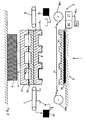
- FIG. 1 shows a schematic section of a packaging machine 1. It is a tray sealer (traysealer), which is used to package items in prefabricated trays (trays).
- the section of the packaging machine 1 shown has a sealing station 2 according to the invention.
- the sealing station 2 is arranged on a machine frame 3, which comprises a lifting mechanism 4.
- a sealing tool 5 is movably mounted on the hoist 4.
- the hoist 4 is configured to move the sealing tool 5 in a direction perpendicular to the machine frame 3 direction.
- the packaging machine 1 comprises a transport plane 6, in which a feed device 7 and a discharge device 8 for transporting packaging trays 9 are arranged.
- the feeding device 7 and the discharge 8 are in this embodiment each band conveyor systems.
- the feeding device 7 is intended to supply the sealing station 2 unsealed packaging trays 9, the discharge device 8 is intended to transport sealed packaging trays 9.
- the sealing station 2 further has, on one side of the sealing tool 5, a unwinding device 10a designed as a roll for a film 11, which in this embodiment is a developable film web.
- the unwinding device 10a is configured to controllably feed the film 11 to the sealing tool 5.
- a winding device 10b is provided to cooperate with the unwinding device 10a and to wind the film 11.
- FIG. 5 shows a section of the packaging machine 1 in the transport direction.
- another unwinding device 10c is provided which cooperates with a windup device 10d to unwrap or wind up another sheet-like film 11a.
- the unwinding device 10c and the winding device 10d are arranged in the transport direction on the left and the right side of the sealing tool 5. This means that the unwinding devices 10a and 10c are arranged at 90 ° offset from one another at the sealing station 2. It is thus possible for the two films 11, 11a, which are designed as webs, to be fed to the sealing tool 5 simultaneously and independently of one another.
- the sealing tool 5 further comprises a lower tray receptacle 12 which cooperates with a lower sealing plate 13 to apply a sealing force to the packaging tray 9 and the film 11.
- the unwinding device 10a and the winding device 10b are coupled to the lower sealing plate 13.
- the sealing tool 5 has an upper shell receptacle 14 which can be coupled to the lower sealing plate 13.
- the upper shell receptacle 14 cooperates with an upper sealing plate 15.
- the lower sealing plate 13 is integrated into the sealing tool 5 so that it can be detached from the lower shell receptacle 12.
- the upper shell receptacle 14 and the lower sealing plate 13 can be coupled to the upper sealing plate 15.
- the lower shell receptacle 12 and the upper shell receptacle 14 can each accommodate a plurality of packaging trays 9. In this example you can the lower tray receptacle 12 and the upper tray receptacle 14 receive three packaging trays 9 in a row.
- the lower shell receptacle 12 and the lower sealing plate 13 and the upper shell receptacle 14 and the upper sealing plate 15 each form an assembly within the sealing tool 5, which are configured to evacuate and / or aerate the packaging trays 9.
- the sealing station 2 has a controllable force device 16, which here is an inflatable membrane.
- the upper sealing plate 15 is coupled, for example by means of a functioning as a guide bolt connection.
- the force device 16 is provided to generate the sealing force to be applied to the packaging shell 9 on the sealing tool 5.
- the lower shell receptacle 12 and the lower sealing plate 13 and the upper shell receptacle 14 and the upper sealing plate 15 are each constructively designed so that they each sealing force on the between the shell holder 12, 14 and the sealing plate 13, 15 arranged packaging shell 9 and the overlapping arranged on the packaging tray 9 slide 11 transmitted.
- a control device 17 is provided, which is connected via an electrical line 17a to the power device 16.
- the control device 17 further interacts with a sensor 17b, which detects, for example, the current sealing force and / or the temperature of the sealing tool 5.
- the data provided by the sensor 17b are processed by the control device 17.
- the sealing station 2 further has a compressor 18 which is configured to cooperate with the control device 17.
- a gripper system 19 is provided.
- the gripper system 19 is configured to simultaneously receive one or more packaging trays 9 from the feeder 7 and to transport them into the lower tray receptacle 12 and / or the upper tray receptacle 14. Furthermore, the gripper system 19 can remove packaging trays 9 from the sealing tool 5 and transfer them to the discharge device 8 for onward transport.
- the feed device 7 and the discharge device 8 are each height adjustable.
- the packaging machine 1 and the sealing station 2 integrated therein work in cycles.
- the sealing tool 5 can receive twice three packaging trays 9, namely three trays 9 in the lower tray receptacle 12 and a further three trays in the upper tray receptacle 13.
- FIG. 2 shows a schematic section of the packaging machine 1 with the sealing station 2 according to the invention in a partially open state.
- the upper shell receptacle 14 is decoupled from the upper sealing plate 15 and lowered by means of Hubewerks 4.
- the now freely accessible upper shell receptacle 14 is fed by means of the gripper system 19, a set of the packaging trays 9, in this example, three pieces.
- the film 11 is introduced by means of the unwinding device 10a and wound on the opposite side of the winding device 10b.
- the film 11 can be introduced into the sealing tool 5 either as a coherent film web or as individual film pieces.
- the packaging machine 1 is shown as a schematic section with the sealing station 2 in a further, partially open state.
- the upper tray receptacle 14 was filled with packaging trays 9
- the upper tray receptacle 14 is now moved in the direction of the upper sealing plate 15 and coupled thereto, so that the upper tray receptacle 14 and the upper sealing plate 15 form a closed unit.
- the lower sealing plate 13 is now moved coupled. This results in a clearance between the lower shell receptacle 12 and the lower sealing plate 13, so that the lower shell receptacle 12 can accommodate a further set of packaging trays 9.
- the gripper system 19 the lower tray receptacle 12 is filled with the packaging trays 9.
- the unwinding 10c leads the space between lower Cup receptacle 12 and lower sealing plate 13, the film 11 a to.
- the film 11a is wound up by the winding device 10d.
- the sealing tool 5 is closed by the hoist 4 moves the lower shell receptacle 12 upwards in the direction of the lower sealing plate 13.
- the lower shell receptacle 12 and the lower seal plate 13 are coupled to each other. Subsequently, the packaging trays 9 of the lower tray receptacle 12 are evacuated.
- FIG. 4 a section of the packaging machine 1 is shown with the sealing station 2 according to the invention during sealing.
- the sealing tool 5 is now raised by means of the hoist 4 in the direction of the controllable power device 16.
- the force device 16 which is a controllable and inflatable membrane as described above, now brings the sealing force, depending on parameters such as the temperature in the sealing tool 5 or the nature of the packaging shell 9 and foil 11, onto the upper sealing plate 15 on.
- the sealing force is transmitted via the upper shell receptacle 14 to the lower sealing plate 13 coupled thereto, so that both sets of packaging trays 9 are sealed with the two sets of films 11 at the same time.
- connection between the upper shell receptacle 14 and the upper sealing plate 15 is separated and opened by lowering the hoist 4, the sealing tool 5, so that by means of the gripper system 19 sealed with the film 11 packaging shells 9 can be removed from the upper tray receptacle 14 ,
- the sealed packaging trays 9 are fed by means of the discharge device 8 either a next workstation (not shown) of the packaging machine 1 or discharged as a finished product from the packaging machine 1.
- another set of the film 11 is also introduced between the upper shell receptacle 14 and the upper sealing plate 15.
- the sealing tool 5 is closed again by the hoist 4 moves again in the direction of power device 16.
- the lower shell receptacle 12 is decoupled from the lower sealing plate 13 so that the lifting mechanism 4 moves downwards with the lower shell receptacle 12 alone.
- the sealing tool 5 opens between the lower shell receptacle 12 and the lower sealing plate 13, so that the sealed with the film 11 set of packaging trays 9 can be removed from the lower tray receptacle 12 by means of the gripper system 19.
- the sealed packaging trays 9 are further transported or removed.
- the packaging machine 1 and the sealing station 2 according to the invention can be modified in many ways.
- the lower and upper tray receivers 12, 14 may each be configured to receive a plurality of tracks of packaging trays 9 simultaneously, such that, for example, two times three trays of packaging trays are disposed in each of the tray receivers 12, 14. It is thus possible that several packaging trays 9 are sealed per working cycle.
Landscapes
- Engineering & Computer Science (AREA)
- Mechanical Engineering (AREA)
- Manufacturing & Machinery (AREA)
- Chemical & Material Sciences (AREA)
- Dispersion Chemistry (AREA)
- Physics & Mathematics (AREA)
- Fluid Mechanics (AREA)
- Closing Of Containers (AREA)
Abstract
Description
- Die Erfindung bezieht sich auf eine Siegelstation für eine Verpackungsmaschine gemäß dem Oberbegriff des Anspruchs 1, auf eine Verpackungsmaschine mit den Merkmalen des Anspruchs 10 sowie auf ein Verfahren gemäß dem Oberbegriff des Anspruchs 11.
- Eine Verpackungsmaschine mit einer Siegelstation geht beispielsweise aus der
DE 102 37 933 A1 hervor. Die Siegelstation umfasst ein Siegelwerkzeug, das mittels Druck eine Deckelfolie auf eine Verpackungsschale, auch als Tray bezeichnet, siegelt. Üblicherweise sind mehrere Verpackungsschalen horizontal nebeneinander und in mehreren Reihen angeordnet. Der für das Siegeln aufzubringende Druck sinkt dabei mit der steigenden Anzahl horizontal angeordneter Verpackungsschalen, da sich die Siegelkraft auf eine größere Fläche verteilt. Nachteilig daran ist, dass die Qualität der Siegelnaht mit sinkendem Siegeldruck nachlässt. - Eine weitere Verpackungsmaschine, die jedoch nicht für das Siegeln von Verpackungsschalen mithilfe einer Siegelkraft bzw. eines Siegeldrucks, sondern als Kammermaschine für das Vakuumverpacken eingerichtet ist, ist in der
US 2005/0178090 A1 beschrieben. Darin sind mehrere einzelne Vakuumkammern übereinander angeordnet und dazu konfiguriert, Gegenstände unabhängig voneinander unter Vakuum zu verpacken. Nachteilig daran ist, dass diese Anordnung keine Verpackungsschalen versiegeln kann. - Aufgabe der vorliegenden Erfindung ist es, eine Siegelstation für eine Verpackungsmaschine zur Verfügung zu stellen, die es mit konstruktiv möglichst einfachen Mitteln erlaubt, eine möglichst hohe Anzahl von Verpackungsschalen zu siegeln.
- Diese Aufgabe wird gelöst durch eine Siegelstation mit den Merkmalen des Anspruchs 1 bzw. durch eine Verpackungsmaschine mit den Merkmalen des Anspruchs 10. Die Erfindung gibt ferner auch ein Verfahren zum Betrieb einer solchen Siegelstation an. Vorteilhafte Weiterbildungen der Erfindung sind in den Unteransprüchen angegeben.
- Die erfindungsgemäße Siegelstation für eine Verpackungsmaschine ist zum Siegeln einer Folie auf eine Verpackungsschale mit einem Siegelwerkzeug konfiguriert. Das Siegelwerkzeug bringt eine Siegelkraft zum Siegeln auf die Folie und die Verpackungsschale auf und zeichnet sich dadurch aus, dass das Siegelwerkzeug eine obere und eine untere Schalenaufnahme umfasst, die in unterschiedlichen Höhen angeordnet und jeweils zur Aufnahme mindestens einer Verpackungsschale konfiguriert sind. Vorteilhaft daran ist, dass es die Ausgestaltung des Siegelwerkzeugs erlaubt, eine Anzahl von Verpackungsschalen in unterschiedlichen Höhen bzw. übereinander anzuordnen. Dadurch kann eine gegenüber der horizontalen Anordnung von Verpackungsschalen gleichbleibende Anzahl von Verpackungsschalen im Siegelwerkzeug aufgenommen werden, ohne dass der Siegeldruck abnimmt. Vielmehr ist es durch eine übereinander liegende Anordnung der Verpackungsschalen möglich, die Wirkfläche der Siegelkraft zu reduzieren und dadurch den Siegeldruck zu erhöhen. Dies bewirkt eine höhere Qualität der Siegelnaht. Das Siegelwerkzeug lässt es aber auch zu, dass die Kapazität des Siegelwerkzeugs bei gleichbleibender Siegelkraft gegenüber der horizontalen Anordnung der Verpackungsschalen nahezu verdoppelt oder allgemein vervielfacht wird, ohne dass der Siegeldruck geringer wird.
- Um die Kapazität der Siegelstation pro Arbeitstakt zu maximieren, kann es vorteilhaft sein, wenn das Siegelwerkzeug dazu konfiguriert ist, die Siegelkraft gleichzeitig auf eine in der oberen Schalenaufnahme aufgenommene Verpackungsschale und eine in der unteren Schalenaufnahme aufgenommene Verpackungsschale aufzubringen. Dadurch kann das Versiegeln gleichzeitig mit mehreren Verpackungsschalen durchgeführt werden.
- In einer besonders vorteilhaften Variante der Erfindung umfasst das Siegelwerkzeug eine obere Siegelplatte und eine untere Siegelplatte. Diese Anordnung ermöglicht ein einfaches und effektives Aufbringen der Siegelkraft auf das Siegelwerkzeug bzw. auf die Verpackungsschale.
- Für eine Parallelisierung von Arbeitsschritten innerhalb der Siegelstation kann es vorteilhaft sein, wenn die obere Schalenaufnahme und die untere Siegelplatte gekoppelt bewegbar sind. Damit kann beispielsweise erreicht werden, dass die obere Schalenaufnahme verschlossen wird, während gleichzeitig die untere Schalenaufnahme geöffnet wird.
- Für ein an die jeweilige Situation angepasstes Aufbringen der Siegelkraft kann es vorteilhaft sein, wenn eine Vorrichtung zum Erfassen der Siegelkraft und zum Regeln der Siegelkraft auf einen bestimmten Wert vorgesehen ist. So kann je nach Beschaffenheit der Folie oder der Verpackungsschale ein individueller Siegeldruck aufgebracht werden. Auch das Regeln der Siegelkraft in Abhängigkeit der Temperatur im Siegelwerkzeug ist möglich.
- Für das Verpacken von verderblichen Lebensmitteln ist es vorteilhaft, wenn das Siegelwerkzeug dazu konfiguriert ist, die Verpackungsschale zu evakuieren.
- Eine vorteilhafte Ausführungsvariante der Erfindung sieht vor, dass die obere und die untere Schalenaufnahme mit einem Hubwerk bewegbar sind. Dies erlaubt eine Höhenverstellung der Schalenaufnahme und gewährleistet eine räumliche Flexibilität.
- Für das effektive Beladen der oberen und unteren Schalenaufnahme kann es vorteilhaft sein, wenn für die Siegelstation ein Greifersystem vorgesehen ist. Idealerweise ermöglicht es das Greifersystem, dass die obere und die untere Schalenaufnahme jeweils unabhängig voneinander beladen werden können.
- Die Erfindung bezieht sich auch auf eine Verpackungsmaschine mit einer Siegelstation der vorstehend beschriebenen Art. Diese Verpackungsmaschine hat den Vorteil, dass die für das Versiegeln notwendige Siegelkraft gleichzeitig auf die untere und auf die obere Schalenaufnahme aufgebracht werden kann bzw. dass mehrere Verpackungsschalen gleichzeitig in übereinander angeordneten Ebenen versiegelt werden können.
- Die Erfindung bezieht sich auch auf ein Verfahren zum Betrieb einer Siegelstation der vorstehend beschriebenen Art. Das Verfahren zeichnet sich dadurch aus, dass eine Siegelkraft gleichzeitig auf wenigstens eine in einer oberen Schalenaufnahme und wenigstens eine in einer unteren Schalenaufnahme befindliche Verpackungsschale aufgebracht wird. Dies hat den Vorteil, dass mehrere Verpackungsschalen gleichzeitig mit einem Siegelwerkzeug in einer Siegelstation versiegelt werden können. Somit können Verpackungsschalen, die sonst horizontal in mehreren Spuren angeordnet wären, übereinander angeordnet werden, sodass sich durch Reduzierung der Siegelfläche bei gleichbleibender Siegelkraft ein höherer Siegeldruck innerhalb des Siegelwerkzeugs ergibt. Es ist auch möglich, die Aufnahmekapazität des Siegelwerkzeugs gegenüber horizontal in gleicher Anzahl angeordneten Verpackungsschalen durch Verdoppelung der Schalenaufnahmen zu erhöhen und zugleich den Siegeldruck beizubehalten.
- Besonders vorteilhaft ist es, wenn dem Siegelwerkzeug in einer zweiten Ebene Verpackungsschalen zugeführt werden, nachdem eine erste Ebene des Siegelwerkzeugs Verpackungsschalen aufgenommen hat. Damit können mehrere Arbeitstakte parallelisiert werden.
- Eine besonders vorteilhafte Variante des Verfahrens sieht vor, dass die erste und die zweite Ebene des Siegelwerkzeugs einzeln evakuiert werden können. Somit kann das Evakuieren in voneinander unabhängigen Arbeitsschritten durchgeführt werden.
- Im Folgenden werden vorteilhafte Ausführungsbeispiele der Erfindung anhand einer Zeichnung näher erläutert. Im Einzelnen zeigen:
- Figur 1
- einen schematischen Ausschnitt einer Verpackungsmaschine mit einer erfindungsgemäßen Siegelstation in der Seitenansicht,
- Figur 2
- einen schematischen Ausschnitt einer Verpackungsmaschine mit einer erfindungsgemäßen Siegelstation in teilweise geöffneten Zustand in der Seitenansicht,
- Figur 3
- einen schematischen Ausschnitt einer Verpackungsmaschine mit einer erfindungsgemäßen Siegelstation in einen anderen teilweise geöffneten Zustand in der Seitenansicht,
- Figur 4
- einen schematischen Ausschnitt einer Verpackungsmaschine mit einer erfindungsgemäßen Siegelstation während des Siegelns, und
- Figur 5
- einen schematischen Ausschnitt einer Verpackungsmaschine in Transportrichtung.
- Gleiche Komponenten sind in den Figuren durchgängig mit gleichen Bezugszeichen versehen.
-
Figur 1 zeigt einen schematischen Ausschnitt einer Verpackungsmaschine 1. Es handelt sich hierbei um eine Schalenschließmaschine (Traysealer), die dazu dient, Gegenstände in vorgefertigte Schalen (Trays) zu verpacken. - Der gezeigte Ausschnitt der Verpackungsmaschine 1 verfügt über eine erfindungsgemäße Siegelstation 2. Die Siegelstation 2 ist auf einem Maschinengestell 3 angeordnet, das ein Hubwerk 4 umfasst. Auf dem Hubwerk 4 ist ein Siegelwerkzeug 5 beweglich angebracht. Das Hubwerk 4 ist dazu konfiguriert, das Siegelwerkzeug 5 in einer zum Maschinengestell 3 senkrechten Richtung zu bewegen.
- Die Verpackungsmaschine 1 umfasst eine Transportebene 6, in der eine Zuführvorrichtung 7 und eine Abführvorrichtung 8 zum Transport von Verpackungsschalen (Trays) 9 angeordnet sind. Die Zuführvorrichtung 7 und die Abführrichtung 8 sind in diesem Ausführungsbeispiel jeweils Bandförderanlagen. Die Zuführvorrichtung 7 ist dazu vorgesehen, der Siegelstation 2 unversiegelte Verpackungsschalen 9 zuzuführen, die Abführvorrichtung 8 ist dazu vorgesehen, versiegelte Verpackungsschalen 9 abzutransportieren.
- Die Siegelstation 2 weist weiter auf einer Seite des Siegelwerkzeugs 5 eine als Rolle ausgeführte Abwickelvorrichtung 10a für eine Folie 11 auf, die in diesem Ausführungsbeispiel eine abwickelbare Folienbahn ist. Die Abwickelvorrichtung 10a ist dazu konfiguriert, dem Siegelwerkzeug 5 steuerbar die Folie 11 zuzuführen. Auf der gegenüberliegenden Seite des Siegelwerkzeugs ist eine Aufwickelvorrichtung 10b vorgesehen, um mit der Abwickelvorrichtung 10a zusammenzuwirken und die Folie 11 aufzuwickeln.
-
Figur 5 zeigt einen Ausschnitt der Verpackungsmaschine 1 in der Transportrichtung. Wie darin dargestellt, ist eine weitere Abwickelvorrichtung 10c vorgesehen, die mit einer Aufwickelvorrichtung 10d zusammenwirkt, um eine weitere bahnförmige Folie 11a ab- bzw. aufzuwickeln. Die Abwickelvorrichtung 10c und die Aufwickelvorrichtung 10d sind in Transportrichtung auf der linken bzw. der rechten Seite des Siegelwerkzeugs 5 angeordnet. Das heißt, dass die Abwickelvorrichtungen 10a und 10c um 90° zueinander versetzt an der Siegelstation 2 angeordnet sind. Damit ist es möglich, dass die zwei als Bahnen ausgeführten Folien 11, 11a gleichzeitig und unabhängig voneinander dem Siegelwerkzeug 5 zugeführt werden können. - Wie in
Figur 1 gezeigt, umfasst das Siegelwerkzeug 5 weiter eine untere Schalenaufnahme 12, die mit einer unteren Siegelplatte 13 zusammenwirkt, um eine Siegelkraft auf die Verpackungsschale 9 und die Folie 11 aufzubringen. An die untere Siegelplatte 13 sind die Abwickelvorrichtung 10a und die Aufwickelvorrichtung 10b gekoppelt. Oberhalb der unteren Siegelplatte 13 weist das Siegelwerkzeug 5 eine obere Schalenaufnahme 14 auf, die mit der unteren Siegelplatte 13 koppelbar ist. Die obere Schalenaufnahme 14 wirkt mit einer oberen Siegelplatte 15 zusammen. Die untere Siegelplatte 13 ist so in das Siegelwerkzeug 5 integriert, dass sie sich von der unteren Schalenaufnahme 12 ablösen lässt. Die obere Schalenaufnahme 14 und die untere Siegelplatte 13 sind an die obere Siegelplatte 15 koppelbar. Die untere Schalenaufnahme 12 und die obere Schalenaufnahme 14 können jeweils mehrere Verpackungsschalen 9 aufnehmen. In diesem Beispiel können die untere Schalenaufnahme 12 und die obere Schalenaufnahme 14 jeweils drei Verpackungsschalen 9 in einer Reihe aufnehmen. Die untere Schalenaufnahme 12 und die untere Siegelplatte 13 bzw. die obere Schalenaufnahme 14 und die obere Siegelplatte 15 bilden jeweils eine Baugruppe innerhalb des Siegelwerkzeugs 5, die dazu konfiguriert sind, die Verpackungsschalen 9 zu evakuieren und/oder zu begasen. - Oberhalb des Siegelwerkzeugs 5 verfügt die Siegelstation 2 über eine steuerbare Kraftvorrichtung 16, die hier eine aufblasbare Membrane ist. An die Kraftvorrichtung 16 ist die obere Siegelplatte 15 gekoppelt, beispielsweise mittels einer als Führung funktionierenden Bolzenverbindung. Die Kraftvorrichtung 16 ist dafür vorgesehen, die zum Siegeln der Verpackungsschale 9 aufzubringende Siegelkraft auf das Siegelwerkzeug 5 zu erzeugen. Dafür sind die untere Schalenaufnahme 12 und die untere Siegelplatte 13 bzw. die obere Schalenaufnahme 14 und die obere Siegelplatte 15 jeweils konstruktiv so ausgeführt, dass sie die Siegelkraft jeweils auf die zwischen der Schalenaufnahme 12, 14 und der Siegelplatte 13, 15 angeordneten Verpackungsschale 9 und die auf der Verpackungsschale 9 überlappend angeordnete Folie 11 übertragen.
- Für die Steuerung der Kraftvorrichtung 16 und das Hubwerk 4 ist eine Steuereinrichtung 17 vorgesehen, die über eine elektrische Leitung 17a an der Kraftvorrichtung 16 angeschlossen ist. Die Steuereinrichtung 17 wirkt weiter mit einer Sensorik 17b zusammen, die beispielsweise die aktuelle Siegelkraft und/oder die Temperatur des Siegelwerkzeugs 5 erfasst. Die von der Sensorik 17b bereitgestellten Daten werden von der Steuereinrichtung 17 verarbeitet. Um die Kraftvorrichtung 16 gesteuert aufzublasen, verfügt die Siegelstation 2 weiter über einen Kompressor 18, der dazu konfiguriert ist, mit der Steuereinrichtung 17 zusammenzuarbeiten.
- Um die untere Schalenaufnahme 12 und die obere Schalenaufnahme 14 zu be- und entladen, ist ein Greifersystem 19 vorgesehen. Das Greifersystem 19 ist dazu konfiguriert, gleichzeitig eine oder mehrere Verpackungsschalen 9 von der Zuführvorrichtung 7 aufzunehmen und in die untere Schalenaufnahme 12 und/oder die obere Schalenaufnahme 14 zu transportieren. Weiter kann das Greifersystem 19 Verpackungsschalen 9 aus dem Siegelwerkzeug 5 entnehmen und der Abführvorrichtung 8 zum Weitertransport übergeben. Um das Greifersystem 19 zu unterstützen, sind die Zuführvorrichtung 7 und die Abführvorrichtung 8 jeweils höhenverstellbar.
- Der Betrieb der erfindungsgemäßen Siegelstation 2 wird nachfolgend anhand einiger Beispiele erläutert.
- Die Verpackungsmaschine 1 und die darin integrierte Siegelstation 2 arbeiten taktweise.
- Ausgehend von dem in
Figur 1 gezeigten Anfangszustand der Siegelstation 2 werden zunächst so viele Verpackungsschalen 9 über die Zuführvorrichtung 7 bereitgestellt, wie von dem Siegelwerkzeug 5 aufgenommen werden können. In diesem Ausführungsbeispiel kann das Siegelwerkzeug 5 zweimal drei Verpackungsschalen 9 aufnehmen, nämlich drei Verpackungsschalen 9 in der unteren Schalenaufnahme 12 und weitere drei Verpackungsschalen in der oberen Schalenaufnahme 13. -
Figur 2 zeigt einen schematischen Ausschnitt der Verpackungsmaschine 1 mit der erfindungsgemäßen Siegelstation 2 in einem teilweise geöffneten Zustand. Die obere Schalenaufnahme 14 wird von der oberen Siegelplatte 15 entkoppelt und mittels des Hubewerks 4 abgesenkt. Der nun frei zugänglichen oberen Schalenaufnahme 14 wird mittels des Greifersystems 19 ein Satz der Verpackungsschalen 9 zugeführt, in diesem Beispiel drei Stück. Ebenso wird in den Zwischenraum zwischen oberer Schalenaufnahme 14 und oberer Siegelplatte 15 die Folie 11 mit Hilfe der Abwickelvorrichtung 10a eingebracht und auf der Gegenseite von der Aufwickelvorrichtung 10b aufgewickelt. Die Folie 11 kann hierfür entweder als zusammenhängende Folienbahn oder aber als einzelne Folienstücke in das Siegelwerkzeug 5 eingebracht werden. - In
Figur 3 ist die Verpackungsmaschine 1 als schematischer Ausschnitt mit der Siegelstation 2 in einem weiteren, teilweise geöffneten Zustand dargestellt. Nachdem, wie zuvor beschrieben, die obere Schalenaufnahme 14 mit Verpackungsschalen 9 befüllt wurde, wird nun die obere Schalenaufnahme 14 in Richtung der oberen Siegelplatte 15 bewegt und mit dieser gekoppelt, so dass die obere Schalenaufnahme 14 und die obere Siegelplatte 15 eine geschlossene Einheit bilden. Mitsamt der oberen Schalenaufnahme 14 wird nun die untere Siegelplatte 13 gekoppelt bewegt. Dadurch ergibt sich ein Freiraum zwischen der unteren Schalenaufnahme 12 und der unteren Siegelplatte 13, so dass die untere Schalenaufnahme 12 einen weiteren Satz von Verpackungsschalen 9 aufnehmen kann. Mittels des Greifersystems 19 wird die untere Schalenaufnahme 12 mit den Verpackungsschalen 9 befüllt. Die Abwickelvorrichtung 10c führt dem Freiraum zwischen unterer Schalenaufnahme 12 und unterer Siegelplatte 13 die Folie 11a zu. Auf der gegenüberliegenden Seite wird die Folie 11a von der Aufwickelvorrichtung 10d aufgewickelt. - Gleichzeitig mit dem Beladen der unteren Schalenaufnahme 12 bzw. nach dem Schließen der oberen Schalenaufnahme 14 werden die Verpackungsschalen 9, die in der oberen Schalenaufnahme 14 angeordnet sind, evakuiert.
- Nach dem Befüllen der unteren Schalenaufnahme 12 wird das Siegelwerkzeug 5 verschlossen, indem das Hubwerk 4 die untere Schalenaufnahme 12 aufwärts in Richtung der unteren Siegelplatte 13 bewegt. Die untere Schalenaufnahme 12 und die untere Siegelplatte 13 werden aneinander gekoppelt. Anschließend werden die Verpackungsschalen 9 der unteren Schalenaufnahme 12 evakuiert.
- In
Figur 4 ist ein Ausschnitt der Verpackungsmaschine 1 mit der erfindungsgemäßen Siegelstation 2 während des Siegelns dargestellt. Nachdem sowohl die obere Schalenaufnahme 14 als auch die untere Schalenaufnahme 12 jeweils mit einem Satz der Verpackungsschalen 9 bestückt sowie die Folie 11 zugeführt und die Verpackungsschalen 9 evakuiert wurden, wird das Siegelwerkzeug 5 nun mit Hilfe des Hubwerks 4 in Richtung der steuerbaren Kraftvorrichtung 16 angehoben. Die Kraftvorrichtung 16, bei dem es sich wie oben beschrieben um eine steuerbare und aufblasbare Membrane handelt, bringt nun die in Abhängigkeit von Parametern, wie beispielsweise der Temperatur im Siegelwerkzeug 5 oder der Beschaffenheit der Verpackungsschale 9 und Folie 11, eingestellte Siegelkraft auf die obere Siegelplatte 15 auf. Die Siegelkraft wird über die obere Schalenaufnahme 14 auf die daran gekoppelte untere Siegelplatte 13 übertragen, sodass beide Sätze von Verpackungsschalen 9 mit den beiden Sätzen von Folien 11 gleichzeitig versiegelt werden. - Nach dem Versiegeln wird die Verbindung zwischen der oberen Schalenaufnahme 14 und der oberen Siegelplatte 15 getrennt und durch Absenken des Hubwerks 4 das Siegelwerkzeug 5 geöffnet, so dass mittels des Greifersystems 19 die mit der Folie 11 versiegelten Verpackungsschalen 9 aus der oberen Schalenaufnahme 14 entfernt werden können. Die versiegelten Verpackungsschalen 9 werden mit Hilfe der Abführvorrichtung 8 entweder einer nächsten Arbeitstation (nicht gezeigt) der Verpackungsmaschine 1 zugeführt oder als fertiges Produkt aus der Verpackungsmaschine 1 abgeführt.
- Ein neuer Satz Verpackungsschalen 9, der über die Zuführvorrichtung 7 bereitgestellt wird, wird mittels des Greifersystems 19 in die Schalenaufnahme 14 eingebracht. Über die Abwickelvorrichtung 10a wird ein weiterer Satz der Folie 11 ebenso zwischen die obere Schalenaufnahme 14 und die obere Siegelplatte 15 eingebracht. Anschließend wird das Siegelwerkzeug 5 erneut verschlossen, indem sich das Hubwerk 4 erneut in Richtung Kraftvorrichtung 16 bewegt. Die untere Schalenaufnahme 12 wird von der unteren Siegelplatte 13 entkoppelt, sodass sich das Hubwerk 4 alleine mit der unteren Schalenaufnahme 12 abwärts bewegt. Somit öffnet sich das Siegelwerkzeug 5 zwischen der unteren Schalenaufnahme 12 und der unteren Siegelplatte 13, so dass der mit der Folie 11 versiegelte Satz von Verpackungsschalen 9 aus der unteren Schalenaufnahme 12 mit Hilfe des Greifersystems 19 entfernt werden kann. Über die Abführvorrichtung 8 werden die versiegelten Verpackungsschalen 9 weiter- bzw. abtransportiert.
- Ausgehend von den dargestellten Ausführungsbeispielen können die Verpackungsmaschine 1 und die erfindungsgemäße Siegelstation 2 in vielfacher Hinsicht abgewandelt werden. Beispielsweise können die untere und die obere Schalenaufnahme 12, 14 jeweils dazu konfiguriert sein, mehrere Spuren von Verpackungsschalen 9 gleichzeitig aufzunehmen, so dass beispielsweise zweimal drei Spuren von Verpackungsschalen in jeder der Schalenaufnahmen 12, 14 angeordnet sind. So ist es möglich, dass pro Arbeitstakt mehrere Verpackungsschalen 9 versiegelt werden.
- Weiter wäre es denkbar, dass weitere Schalenaufnahmen zusätzlich zu den Schalenaufnahmen 12, 14 vorgesehen werden, die entsprechend übereinander angeordnet sind. Somit könnte die Aufnahmekapazität der Siegelstation 2 zusätzlich gesteigert werden.
Claims (13)
- Siegelstation (2) für eine Verpackungsmaschine (1) zum Siegeln einer Folie (11) auf eine Verpackungsschale (9), mit einem Siegelwerkzeug (5), wobei das Siegelwerkzeug (5) dazu konfiguriert ist, eine Siegelkraft zum Siegeln auf die Folie (11) und die Verpackungsschale (9) aufzubringen, dadurch gekennzeichnet, dass das Siegelwerkzeug (5) eine obere und eine untere Schalenaufnahme (14, 12) umfasst, die in unterschiedlichen Höhen angeordnet und jeweils zur Aufnahme mindestens einer Verpackungsschale (9) konfiguriert sind.
- Siegelstation nach Anspruch 1, dadurch gekennzeichnet, dass das Siegelwerkzeug dazu konfiguriert ist, die Siegelkraft gleichzeitig auf eine in der oberen Schalenaufnahme (14) aufgenommene Verpackungsschale (9) und eine in der unteren Schalenaufnahme (12) aufgenommene Verpackungsschale (9) aufzubringen.
- Siegelstation nach Anspruch 1 oder 2, dadurch gekennzeichnet, dass das Siegelwerkzeug (5) eine obere Siegelplatte (15) und eine untere Siegelplatte (13) umfasst.
- Siegelstation nach Anspruch 3, dadurch gekennzeichnet, dass die obere Schalenaufnahme (14) und die untere Siegelplatte (13) gekoppelt bewegbar sind.
- Siegelstation nach einem der vorangehenden Ansprüche, dadurch gekennzeichnet, dass eine steuerbare Kraftvorrichtung (16) vorgesehen ist, um die Siegelkraft aufzubringen.
- Siegelstation nach einem der vorangehenden Ansprüche, dadurch gekennzeichnet, dass eine Vorrichtung (17) zum Erfassen der Siegelkraft und zum Regeln der Siegelkraft auf einen bestimmten Wert vorgesehen ist.
- Siegelstation nach einem der vorangehenden Ansprüche, dadurch gekennzeichnet, dass das Siegelwerkzeug (5) dazu konfiguriert ist, die Verpackungsschale (9) zu evakuieren und/oder zu begasen.
- Siegelstation nach einem der vorangehenden Ansprüche, dadurch gekennzeichnet, dass die obere und die untere Schalenaufnahme (14, 12) mit einem Hubwerk (4) bewegbar sind.
- Siegelstation nach einem der vorangehenden Ansprüche, dadurch gekennzeichnet, dass für die Siegelstation (2) ein Greifersystem (19) vorgesehen ist.
- Verpackungsmaschine (1) mit einer Siegelstation (2) nach einem der Ansprüche 1 bis 9.
- Verfahren zum Betrieb einer Siegelstation (1), dadurch gekennzeichnet, dass eine Siegelkraft gleichzeitig auf wenigstens eine in einer oberen Schalenaufnahme (14) und wenigstens eine in einer unteren Schalenaufnahme (12) befindliche Verpackungsschale (9) aufgebracht wird.
- Verfahren nach Anspruch 11, dadurch gekennzeichnet, dass einem Siegelwerkzeug (5) in einer zweiten Ebene Verpackungsschalen (9) zugeführt werden, nachdem eine erste Ebene des Siegelwerkzeugs (5) Verpackungsschalen (9) aufgenommen hat.
- Verfahren nach Anspruch 12, dadurch gekennzeichnet, dass die erste und die zweite Ebene des Siegelwerkzeugs (5) einzeln evakuiert werden und/oder zu begasen.
Applications Claiming Priority (1)
| Application Number | Priority Date | Filing Date | Title |
|---|---|---|---|
| DE102011110407A DE102011110407B3 (de) | 2011-08-12 | 2011-08-12 | Siegelstation und Verfahren für deren Betrieb |
Publications (1)
| Publication Number | Publication Date |
|---|---|
| EP2557042A1 true EP2557042A1 (de) | 2013-02-13 |
Family
ID=46880547
Family Applications (1)
| Application Number | Title | Priority Date | Filing Date |
|---|---|---|---|
| EP12005762A Withdrawn EP2557042A1 (de) | 2011-08-12 | 2012-08-08 | Siegelstation und Verfahren für deren Betrieb |
Country Status (3)
| Country | Link |
|---|---|
| US (1) | US20130055688A1 (de) |
| EP (1) | EP2557042A1 (de) |
| DE (1) | DE102011110407B3 (de) |
Cited By (1)
| Publication number | Priority date | Publication date | Assignee | Title |
|---|---|---|---|---|
| EP3608234A1 (de) * | 2018-08-07 | 2020-02-12 | MULTIVAC Sepp Haggenmüller SE & Co. KG | Verfahren zum betrieb einer schalenverschliessmaschine |
Families Citing this family (9)
| Publication number | Priority date | Publication date | Assignee | Title |
|---|---|---|---|---|
| EP2441683B1 (de) * | 2010-10-12 | 2012-12-12 | MULTIVAC Sepp Haggenmüller GmbH & Co KG | Verschließstation und Verfahren zum Schneiden einer Deckelfolie |
| DE102012006696A1 (de) * | 2012-03-30 | 2013-10-02 | Multivac Sepp Haggenmüller Gmbh & Co. Kg | Verpackungsmaschine mit einer Siegelvorrichtung |
| US10875670B2 (en) * | 2016-11-04 | 2020-12-29 | Alkar-Rapidpak, Inc. | Web-packaging machines with multiple sealing stations |
| US11136154B2 (en) * | 2017-09-22 | 2021-10-05 | Atlanta Attachment Company | Packaging machine for bedding products |
| DE102018213431A1 (de) * | 2018-08-09 | 2020-02-13 | Multivac Sepp Haggenmüller Se & Co. Kg | Siegelwerkzeug für eine Verpackungsmaschine |
| DE102018222836A1 (de) * | 2018-12-21 | 2020-06-25 | Multivac Sepp Haggenmüller Se & Co. Kg | Siegeln von kartonzuschnitten mittels auflage auf transportband |
| DE102022107346A1 (de) * | 2022-03-29 | 2023-10-05 | Multivac Sepp Haggenmüller Se & Co. Kg | Hubwerk mit Verriegelung sowie Verfahren |
| CN116002111A (zh) * | 2023-03-27 | 2023-04-25 | 成都斯马特科技有限公司 | 一种自动热封机构及方法 |
| DE102023113936A1 (de) * | 2023-05-26 | 2024-11-28 | Körber Pharma Packaging GmbH | Verfahren und system zur überwachung eines fügeprozesses |
Citations (10)
| Publication number | Priority date | Publication date | Assignee | Title |
|---|---|---|---|---|
| US3792567A (en) * | 1971-12-07 | 1974-02-19 | Dixie Packaging Co Inc | Heat sealing machine |
| DE3941183A1 (de) * | 1989-12-13 | 1991-06-20 | Multivac Haggenmueller Kg | Verpackungsmaschine zum herstellen einer ein produkt aufnehmenden wiederverschliessbaren packung |
| WO1996009958A1 (en) * | 1994-09-28 | 1996-04-04 | Tetra Laval Holdings & Finance S.A. | Ultrasonic carton sealer |
| DE10237933A1 (de) | 2002-08-14 | 2004-02-26 | Multivac Sepp Haggenmüller Gmbh & Co. Kg | Verfahren und Verpackungsmaschine zum Verpacken eines in einer Schale befindlichen Produktes |
| US20050178090A1 (en) | 2002-02-27 | 2005-08-18 | John Koke | Vacuum packaging machine |
| WO2006051305A1 (en) * | 2004-11-13 | 2006-05-18 | Edward James Harding | Utensil shaped container |
| DE102009037107A1 (de) * | 2009-08-11 | 2011-02-17 | Sauerlandfrische Dornseifer Gmbh & Co.Kg | Abgepacktes Fertiggericht und Verfahren zu seiner Herstellung |
| US20110072764A1 (en) * | 2009-09-30 | 2011-03-31 | Ross Industries, Inc. | Method and apparatus for sealing containers |
| DE102009049179A1 (de) * | 2009-10-13 | 2011-04-21 | Multivac Sepp Haggenmüller Gmbh & Co. Kg | Verfahren und Verpackungsmaschine zum Verpacken von Produkten |
| US20110094195A1 (en) * | 2008-03-05 | 2011-04-28 | Sarong S.P.A. | Apparatuses and methods for producing containers |
Family Cites Families (2)
| Publication number | Priority date | Publication date | Assignee | Title |
|---|---|---|---|---|
| US6701993B2 (en) * | 2000-11-27 | 2004-03-09 | Harpak, Inc. | Tray sealing system incorporating beaded seal plate |
| US7196290B2 (en) * | 2003-06-02 | 2007-03-27 | Planet Products Corporation | Heat sealer with platen surface temperature sensor and load sensor |
-
2011
- 2011-08-12 DE DE102011110407A patent/DE102011110407B3/de not_active Expired - Fee Related
-
2012
- 2012-08-08 EP EP12005762A patent/EP2557042A1/de not_active Withdrawn
- 2012-08-10 US US13/572,411 patent/US20130055688A1/en not_active Abandoned
Patent Citations (10)
| Publication number | Priority date | Publication date | Assignee | Title |
|---|---|---|---|---|
| US3792567A (en) * | 1971-12-07 | 1974-02-19 | Dixie Packaging Co Inc | Heat sealing machine |
| DE3941183A1 (de) * | 1989-12-13 | 1991-06-20 | Multivac Haggenmueller Kg | Verpackungsmaschine zum herstellen einer ein produkt aufnehmenden wiederverschliessbaren packung |
| WO1996009958A1 (en) * | 1994-09-28 | 1996-04-04 | Tetra Laval Holdings & Finance S.A. | Ultrasonic carton sealer |
| US20050178090A1 (en) | 2002-02-27 | 2005-08-18 | John Koke | Vacuum packaging machine |
| DE10237933A1 (de) | 2002-08-14 | 2004-02-26 | Multivac Sepp Haggenmüller Gmbh & Co. Kg | Verfahren und Verpackungsmaschine zum Verpacken eines in einer Schale befindlichen Produktes |
| WO2006051305A1 (en) * | 2004-11-13 | 2006-05-18 | Edward James Harding | Utensil shaped container |
| US20110094195A1 (en) * | 2008-03-05 | 2011-04-28 | Sarong S.P.A. | Apparatuses and methods for producing containers |
| DE102009037107A1 (de) * | 2009-08-11 | 2011-02-17 | Sauerlandfrische Dornseifer Gmbh & Co.Kg | Abgepacktes Fertiggericht und Verfahren zu seiner Herstellung |
| US20110072764A1 (en) * | 2009-09-30 | 2011-03-31 | Ross Industries, Inc. | Method and apparatus for sealing containers |
| DE102009049179A1 (de) * | 2009-10-13 | 2011-04-21 | Multivac Sepp Haggenmüller Gmbh & Co. Kg | Verfahren und Verpackungsmaschine zum Verpacken von Produkten |
Cited By (1)
| Publication number | Priority date | Publication date | Assignee | Title |
|---|---|---|---|---|
| EP3608234A1 (de) * | 2018-08-07 | 2020-02-12 | MULTIVAC Sepp Haggenmüller SE & Co. KG | Verfahren zum betrieb einer schalenverschliessmaschine |
Also Published As
| Publication number | Publication date |
|---|---|
| DE102011110407B3 (de) | 2013-01-17 |
| US20130055688A1 (en) | 2013-03-07 |
Similar Documents
| Publication | Publication Date | Title |
|---|---|---|
| DE102011110407B3 (de) | Siegelstation und Verfahren für deren Betrieb | |
| DE102009049179B4 (de) | Verfahren und Verpackungsmaschine zum Verpacken von Produkten | |
| EP2539125B1 (de) | Verfahren zum wechsel des ober- und unterwerkzeugs einer verpackungsmaschine | |
| EP2522581B1 (de) | Arbeitsstation für eine Verpackungsmaschine und Verfahren zum Werkzeugwechsel | |
| DE69703508T2 (de) | Verfahren zur Herstellung von sterilen Packungen für Nahtmaterial | |
| EP0710605B1 (de) | Verfahren und Vorrichtung zum Maximieren der Taktgeschwindigkeit einer Vakuumverpackungsmaschine | |
| EP2240369B1 (de) | Verpackungsvorrichtung und -verfahren zum gruppieren einer packformation von gebinden | |
| EP3969377A1 (de) | Verpackungsvorrichtung und verfahren zur herstellung von verpackungseinheiten | |
| EP0023264B1 (de) | Verpackungsvorrichtung | |
| EP2251264B1 (de) | Verpackungsmaschine und Verfahren zum Verschließen von Behältern mit Deckeln | |
| EP2746173B1 (de) | Tiefziehverpackungsmaschine und verfahren | |
| EP2517963B1 (de) | Verpackungsmaschine mit Transporteinrichtung | |
| EP0265599A2 (de) | Tiefziehmaschine zum Herstellen von Behältern aus thermoplastischer Folie mit einer eine Schneideinrichtung aufweisenden Banderolievorrichtung | |
| DE102017208753A1 (de) | Vorrichtung und ein Verfahren zum Überführen mindestens einer palettierfähigen Lage auf eine Ablage- und/oder Stapelfläche | |
| DE102012018974A1 (de) | Tiefziehverpackungsmaschine mit Stempelformung | |
| EP0621185A1 (de) | Vorrichtung zum Fördern und Bearbeiten von Fliessmittelpackungen | |
| EP3109018A1 (de) | Tiefziehverpackungsmaschine mit komplettschnittstation und entsprechendes verfahren | |
| EP4013686A1 (de) | Verpackungsmaschine und verfahren zur herstellung von gebinden | |
| WO1992020580A1 (de) | Vorrichtung zum füllen und verschliessen von fliessmittelpackungen | |
| DE102017125973B4 (de) | Verfahren zum Bearbeiten und/oder Füllen von Verpackungen | |
| EP2778081B1 (de) | Verpackungsanlage mit Einraststation und Verfahren | |
| EP1515894B1 (de) | Anlage zum verpacken eines in zickzackförmige schlaufen gelegten flexiblen bandes, insbesondere eines textilbandes | |
| DE19750075A1 (de) | Verfahren und Vorrichtung zum Herstellen und Aufbringen von Deckeln aus einer Werkstoffbahn, insbesondere Deckblattfolien aus einer dünnen Kunststoffolienbahn | |
| DE102008041016A1 (de) | Verfahren und Vorrichtung zum stirnseitigen Verpacken von Materialbahnrollen | |
| EP1575831B1 (de) | Vorrichtung und verfahren zur verpackung von gebinden, insbesondere flaschengebinden |
Legal Events
| Date | Code | Title | Description |
|---|---|---|---|
| PUAI | Public reference made under article 153(3) epc to a published international application that has entered the european phase |
Free format text: ORIGINAL CODE: 0009012 |
|
| AK | Designated contracting states |
Kind code of ref document: A1 Designated state(s): AL AT BE BG CH CY CZ DE DK EE ES FI FR GB GR HR HU IE IS IT LI LT LU LV MC MK MT NL NO PL PT RO RS SE SI SK SM TR |
|
| AX | Request for extension of the european patent |
Extension state: BA ME |
|
| 17P | Request for examination filed |
Effective date: 20130719 |
|
| RBV | Designated contracting states (corrected) |
Designated state(s): AL AT BE BG CH CY CZ DE DK EE ES FI FR GB GR HR HU IE IS IT LI LT LU LV MC MK MT NL NO PL PT RO RS SE SI SK SM TR |
|
| GRAP | Despatch of communication of intention to grant a patent |
Free format text: ORIGINAL CODE: EPIDOSNIGR1 |
|
| INTG | Intention to grant announced |
Effective date: 20140103 |
|
| STAA | Information on the status of an ep patent application or granted ep patent |
Free format text: STATUS: THE APPLICATION IS DEEMED TO BE WITHDRAWN |
|
| 18D | Application deemed to be withdrawn |
Effective date: 20140514 |