EP2556554B1 - Brennstoffzelle mit einer membran mit lokalisierter ionenleitung und verfahren zu dessen herstellung - Google Patents
Brennstoffzelle mit einer membran mit lokalisierter ionenleitung und verfahren zu dessen herstellung Download PDFInfo
- Publication number
- EP2556554B1 EP2556554B1 EP11730337.0A EP11730337A EP2556554B1 EP 2556554 B1 EP2556554 B1 EP 2556554B1 EP 11730337 A EP11730337 A EP 11730337A EP 2556554 B1 EP2556554 B1 EP 2556554B1
- Authority
- EP
- European Patent Office
- Prior art keywords
- membrane
- fuel cell
- ionically
- polymer
- conducting
- Prior art date
- Legal status (The legal status is an assumption and is not a legal conclusion. Google has not performed a legal analysis and makes no representation as to the accuracy of the status listed.)
- Not-in-force
Links
- 239000012528 membrane Substances 0.000 title claims description 99
- 239000000446 fuel Substances 0.000 title claims description 65
- 238000004519 manufacturing process Methods 0.000 title claims description 16
- 238000000034 method Methods 0.000 title claims description 14
- 229920001940 conductive polymer Polymers 0.000 claims description 37
- 229920000642 polymer Polymers 0.000 claims description 19
- 239000000463 material Substances 0.000 claims description 14
- 239000004020 conductor Substances 0.000 claims description 13
- 230000007062 hydrolysis Effects 0.000 claims description 12
- 238000006460 hydrolysis reaction Methods 0.000 claims description 12
- 239000005518 polymer electrolyte Substances 0.000 claims description 12
- 125000000542 sulfonic acid group Chemical group 0.000 claims description 10
- 230000001070 adhesive effect Effects 0.000 claims description 9
- 239000002322 conducting polymer Substances 0.000 claims description 9
- 239000000853 adhesive Substances 0.000 claims description 8
- 125000002128 sulfonyl halide group Chemical group 0.000 claims description 6
- PXHVJJICTQNCMI-UHFFFAOYSA-N Nickel Chemical compound [Ni] PXHVJJICTQNCMI-UHFFFAOYSA-N 0.000 claims description 4
- 230000015572 biosynthetic process Effects 0.000 claims description 4
- 230000015556 catabolic process Effects 0.000 claims description 4
- 238000006731 degradation reaction Methods 0.000 claims description 4
- 229910052751 metal Inorganic materials 0.000 claims description 4
- 239000002184 metal Substances 0.000 claims description 4
- 239000004593 Epoxy Substances 0.000 claims description 3
- 239000002390 adhesive tape Substances 0.000 claims description 3
- 238000006243 chemical reaction Methods 0.000 claims description 3
- 239000003792 electrolyte Substances 0.000 claims description 3
- 239000003292 glue Substances 0.000 claims description 3
- 150000002739 metals Chemical class 0.000 claims description 3
- 229920001296 polysiloxane Polymers 0.000 claims description 3
- 229920002635 polyurethane Polymers 0.000 claims description 3
- 239000004814 polyurethane Substances 0.000 claims description 3
- OKTJSMMVPCPJKN-UHFFFAOYSA-N Carbon Chemical compound [C] OKTJSMMVPCPJKN-UHFFFAOYSA-N 0.000 claims description 2
- RYGMFSIKBFXOCR-UHFFFAOYSA-N Copper Chemical compound [Cu] RYGMFSIKBFXOCR-UHFFFAOYSA-N 0.000 claims description 2
- BQCADISMDOOEFD-UHFFFAOYSA-N Silver Chemical compound [Ag] BQCADISMDOOEFD-UHFFFAOYSA-N 0.000 claims description 2
- 229910045601 alloy Inorganic materials 0.000 claims description 2
- 239000000956 alloy Substances 0.000 claims description 2
- 229910052782 aluminium Inorganic materials 0.000 claims description 2
- XAGFODPZIPBFFR-UHFFFAOYSA-N aluminium Chemical compound [Al] XAGFODPZIPBFFR-UHFFFAOYSA-N 0.000 claims description 2
- 229910052799 carbon Inorganic materials 0.000 claims description 2
- 239000004568 cement Substances 0.000 claims description 2
- 239000010949 copper Substances 0.000 claims description 2
- 229910052802 copper Inorganic materials 0.000 claims description 2
- 125000000524 functional group Chemical group 0.000 claims description 2
- PCHJSUWPFVWCPO-UHFFFAOYSA-N gold Chemical compound [Au] PCHJSUWPFVWCPO-UHFFFAOYSA-N 0.000 claims description 2
- 229910052737 gold Inorganic materials 0.000 claims description 2
- 239000010931 gold Substances 0.000 claims description 2
- 229910052759 nickel Inorganic materials 0.000 claims description 2
- 229910052709 silver Inorganic materials 0.000 claims description 2
- 239000004332 silver Substances 0.000 claims description 2
- 239000000126 substance Substances 0.000 claims description 2
- 239000002966 varnish Substances 0.000 claims description 2
- 239000002861 polymer material Substances 0.000 claims 2
- 239000004411 aluminium Substances 0.000 claims 1
- 230000004048 modification Effects 0.000 claims 1
- 238000012986 modification Methods 0.000 claims 1
- 238000005476 soldering Methods 0.000 claims 1
- 229920000557 Nafion® Polymers 0.000 description 20
- HEMHJVSKTPXQMS-UHFFFAOYSA-M Sodium hydroxide Chemical compound [OH-].[Na+] HEMHJVSKTPXQMS-UHFFFAOYSA-M 0.000 description 9
- BDHFUVZGWQCTTF-UHFFFAOYSA-N sulfonic acid Chemical group OS(=O)=O BDHFUVZGWQCTTF-UHFFFAOYSA-N 0.000 description 6
- 239000004744 fabric Substances 0.000 description 5
- 239000007789 gas Substances 0.000 description 5
- 230000035882 stress Effects 0.000 description 4
- 239000000835 fiber Substances 0.000 description 3
- 230000005012 migration Effects 0.000 description 3
- 238000013508 migration Methods 0.000 description 3
- RLOWWWKZYUNIDI-UHFFFAOYSA-N phosphinic chloride Chemical compound ClP=O RLOWWWKZYUNIDI-UHFFFAOYSA-N 0.000 description 3
- 230000008961 swelling Effects 0.000 description 3
- 238000003856 thermoforming Methods 0.000 description 3
- XLYOFNOQVPJJNP-UHFFFAOYSA-N water Substances O XLYOFNOQVPJJNP-UHFFFAOYSA-N 0.000 description 3
- QAOWNCQODCNURD-UHFFFAOYSA-N Sulfuric acid Chemical compound OS(O)(=O)=O QAOWNCQODCNURD-UHFFFAOYSA-N 0.000 description 2
- 230000008901 benefit Effects 0.000 description 2
- 238000010438 heat treatment Methods 0.000 description 2
- 239000000203 mixture Substances 0.000 description 2
- XHXFXVLFKHQFAL-UHFFFAOYSA-N phosphoryl trichloride Chemical compound ClP(Cl)(Cl)=O XHXFXVLFKHQFAL-UHFFFAOYSA-N 0.000 description 2
- 238000005240 physical vapour deposition Methods 0.000 description 2
- 238000009877 rendering Methods 0.000 description 2
- 239000011734 sodium Substances 0.000 description 2
- YBBRCQOCSYXUOC-UHFFFAOYSA-N sulfuryl dichloride Chemical compound ClS(Cl)(=O)=O YBBRCQOCSYXUOC-UHFFFAOYSA-N 0.000 description 2
- UFHFLCQGNIYNRP-UHFFFAOYSA-N Hydrogen Chemical compound [H][H] UFHFLCQGNIYNRP-UHFFFAOYSA-N 0.000 description 1
- DGAQECJNVWCQMB-PUAWFVPOSA-M Ilexoside XXIX Chemical compound C[C@@H]1CC[C@@]2(CC[C@@]3(C(=CC[C@H]4[C@]3(CC[C@@H]5[C@@]4(CC[C@@H](C5(C)C)OS(=O)(=O)[O-])C)C)[C@@H]2[C@]1(C)O)C)C(=O)O[C@H]6[C@@H]([C@H]([C@@H]([C@H](O6)CO)O)O)O.[Na+] DGAQECJNVWCQMB-PUAWFVPOSA-M 0.000 description 1
- 239000002253 acid Substances 0.000 description 1
- 230000032683 aging Effects 0.000 description 1
- QVGXLLKOCUKJST-UHFFFAOYSA-N atomic oxygen Chemical compound [O] QVGXLLKOCUKJST-UHFFFAOYSA-N 0.000 description 1
- JXLHNMVSKXFWAO-UHFFFAOYSA-N azane;7-fluoro-2,1,3-benzoxadiazole-4-sulfonic acid Chemical compound N.OS(=O)(=O)C1=CC=C(F)C2=NON=C12 JXLHNMVSKXFWAO-UHFFFAOYSA-N 0.000 description 1
- 238000003486 chemical etching Methods 0.000 description 1
- 238000005229 chemical vapour deposition Methods 0.000 description 1
- 230000007797 corrosion Effects 0.000 description 1
- 238000005260 corrosion Methods 0.000 description 1
- 230000007423 decrease Effects 0.000 description 1
- 238000000151 deposition Methods 0.000 description 1
- 230000008021 deposition Effects 0.000 description 1
- 238000001035 drying Methods 0.000 description 1
- 238000004070 electrodeposition Methods 0.000 description 1
- 238000005530 etching Methods 0.000 description 1
- 239000002360 explosive Substances 0.000 description 1
- 229910052739 hydrogen Inorganic materials 0.000 description 1
- 239000001257 hydrogen Substances 0.000 description 1
- 230000006872 improvement Effects 0.000 description 1
- 230000010354 integration Effects 0.000 description 1
- 150000002500 ions Chemical class 0.000 description 1
- 238000013532 laser treatment Methods 0.000 description 1
- 239000007788 liquid Substances 0.000 description 1
- 230000000873 masking effect Effects 0.000 description 1
- 229910001092 metal group alloy Inorganic materials 0.000 description 1
- 239000007769 metal material Substances 0.000 description 1
- 229910052760 oxygen Inorganic materials 0.000 description 1
- 239000001301 oxygen Substances 0.000 description 1
- UHZYTMXLRWXGPK-UHFFFAOYSA-N phosphorus pentachloride Chemical compound ClP(Cl)(Cl)(Cl)Cl UHZYTMXLRWXGPK-UHFFFAOYSA-N 0.000 description 1
- 239000002201 polymeric electrolyte material Substances 0.000 description 1
- 239000011148 porous material Substances 0.000 description 1
- 239000000843 powder Substances 0.000 description 1
- 238000007789 sealing Methods 0.000 description 1
- 238000000926 separation method Methods 0.000 description 1
- 238000002791 soaking Methods 0.000 description 1
- 229910052708 sodium Inorganic materials 0.000 description 1
- 150000003461 sulfonyl halides Chemical class 0.000 description 1
- OBTWBSRJZRCYQV-UHFFFAOYSA-N sulfuryl difluoride Chemical compound FS(F)(=O)=O OBTWBSRJZRCYQV-UHFFFAOYSA-N 0.000 description 1
- -1 sulphonyl halide Chemical class 0.000 description 1
- 229920001169 thermoplastic Polymers 0.000 description 1
- 229920001187 thermosetting polymer Polymers 0.000 description 1
- 239000004416 thermosoftening plastic Substances 0.000 description 1
- 238000011282 treatment Methods 0.000 description 1
- 238000003466 welding Methods 0.000 description 1
- 238000009736 wetting Methods 0.000 description 1
Images




Classifications
-
- H—ELECTRICITY
- H01—ELECTRIC ELEMENTS
- H01M—PROCESSES OR MEANS, e.g. BATTERIES, FOR THE DIRECT CONVERSION OF CHEMICAL ENERGY INTO ELECTRICAL ENERGY
- H01M8/00—Fuel cells; Manufacture thereof
- H01M8/10—Fuel cells with solid electrolytes
- H01M8/1004—Fuel cells with solid electrolytes characterised by membrane-electrode assemblies [MEA]
-
- H—ELECTRICITY
- H01—ELECTRIC ELEMENTS
- H01M—PROCESSES OR MEANS, e.g. BATTERIES, FOR THE DIRECT CONVERSION OF CHEMICAL ENERGY INTO ELECTRICAL ENERGY
- H01M8/00—Fuel cells; Manufacture thereof
- H01M8/02—Details
- H01M8/0271—Sealing or supporting means around electrodes, matrices or membranes
- H01M8/0276—Sealing means characterised by their form
-
- H—ELECTRICITY
- H01—ELECTRIC ELEMENTS
- H01M—PROCESSES OR MEANS, e.g. BATTERIES, FOR THE DIRECT CONVERSION OF CHEMICAL ENERGY INTO ELECTRICAL ENERGY
- H01M8/00—Fuel cells; Manufacture thereof
- H01M8/02—Details
- H01M8/0271—Sealing or supporting means around electrodes, matrices or membranes
- H01M8/028—Sealing means characterised by their material
-
- H—ELECTRICITY
- H01—ELECTRIC ELEMENTS
- H01M—PROCESSES OR MEANS, e.g. BATTERIES, FOR THE DIRECT CONVERSION OF CHEMICAL ENERGY INTO ELECTRICAL ENERGY
- H01M8/00—Fuel cells; Manufacture thereof
- H01M8/10—Fuel cells with solid electrolytes
- H01M8/1016—Fuel cells with solid electrolytes characterised by the electrolyte material
-
- H—ELECTRICITY
- H01—ELECTRIC ELEMENTS
- H01M—PROCESSES OR MEANS, e.g. BATTERIES, FOR THE DIRECT CONVERSION OF CHEMICAL ENERGY INTO ELECTRICAL ENERGY
- H01M8/00—Fuel cells; Manufacture thereof
- H01M8/24—Grouping of fuel cells, e.g. stacking of fuel cells
- H01M8/241—Grouping of fuel cells, e.g. stacking of fuel cells with solid or matrix-supported electrolytes
-
- H—ELECTRICITY
- H01—ELECTRIC ELEMENTS
- H01M—PROCESSES OR MEANS, e.g. BATTERIES, FOR THE DIRECT CONVERSION OF CHEMICAL ENERGY INTO ELECTRICAL ENERGY
- H01M8/00—Fuel cells; Manufacture thereof
- H01M8/24—Grouping of fuel cells, e.g. stacking of fuel cells
- H01M8/241—Grouping of fuel cells, e.g. stacking of fuel cells with solid or matrix-supported electrolytes
- H01M8/2418—Grouping by arranging unit cells in a plane
-
- H—ELECTRICITY
- H01—ELECTRIC ELEMENTS
- H01M—PROCESSES OR MEANS, e.g. BATTERIES, FOR THE DIRECT CONVERSION OF CHEMICAL ENERGY INTO ELECTRICAL ENERGY
- H01M8/00—Fuel cells; Manufacture thereof
- H01M8/24—Grouping of fuel cells, e.g. stacking of fuel cells
- H01M8/2465—Details of groupings of fuel cells
- H01M8/2484—Details of groupings of fuel cells characterised by external manifolds
- H01M8/2485—Arrangements for sealing external manifolds; Arrangements for mounting external manifolds around a stack
-
- H—ELECTRICITY
- H01—ELECTRIC ELEMENTS
- H01M—PROCESSES OR MEANS, e.g. BATTERIES, FOR THE DIRECT CONVERSION OF CHEMICAL ENERGY INTO ELECTRICAL ENERGY
- H01M8/00—Fuel cells; Manufacture thereof
- H01M8/10—Fuel cells with solid electrolytes
- H01M2008/1095—Fuel cells with polymeric electrolytes
-
- Y—GENERAL TAGGING OF NEW TECHNOLOGICAL DEVELOPMENTS; GENERAL TAGGING OF CROSS-SECTIONAL TECHNOLOGIES SPANNING OVER SEVERAL SECTIONS OF THE IPC; TECHNICAL SUBJECTS COVERED BY FORMER USPC CROSS-REFERENCE ART COLLECTIONS [XRACs] AND DIGESTS
- Y02—TECHNOLOGIES OR APPLICATIONS FOR MITIGATION OR ADAPTATION AGAINST CLIMATE CHANGE
- Y02E—REDUCTION OF GREENHOUSE GAS [GHG] EMISSIONS, RELATED TO ENERGY GENERATION, TRANSMISSION OR DISTRIBUTION
- Y02E60/00—Enabling technologies; Technologies with a potential or indirect contribution to GHG emissions mitigation
- Y02E60/30—Hydrogen technology
- Y02E60/50—Fuel cells
-
- Y—GENERAL TAGGING OF NEW TECHNOLOGICAL DEVELOPMENTS; GENERAL TAGGING OF CROSS-SECTIONAL TECHNOLOGIES SPANNING OVER SEVERAL SECTIONS OF THE IPC; TECHNICAL SUBJECTS COVERED BY FORMER USPC CROSS-REFERENCE ART COLLECTIONS [XRACs] AND DIGESTS
- Y02—TECHNOLOGIES OR APPLICATIONS FOR MITIGATION OR ADAPTATION AGAINST CLIMATE CHANGE
- Y02P—CLIMATE CHANGE MITIGATION TECHNOLOGIES IN THE PRODUCTION OR PROCESSING OF GOODS
- Y02P70/00—Climate change mitigation technologies in the production process for final industrial or consumer products
- Y02P70/50—Manufacturing or production processes characterised by the final manufactured product
-
- Y—GENERAL TAGGING OF NEW TECHNOLOGICAL DEVELOPMENTS; GENERAL TAGGING OF CROSS-SECTIONAL TECHNOLOGIES SPANNING OVER SEVERAL SECTIONS OF THE IPC; TECHNICAL SUBJECTS COVERED BY FORMER USPC CROSS-REFERENCE ART COLLECTIONS [XRACs] AND DIGESTS
- Y10—TECHNICAL SUBJECTS COVERED BY FORMER USPC
- Y10T—TECHNICAL SUBJECTS COVERED BY FORMER US CLASSIFICATION
- Y10T156/00—Adhesive bonding and miscellaneous chemical manufacture
- Y10T156/10—Methods of surface bonding and/or assembly therefor
Definitions
- the invention also relates to a method of manufacturing a fuel cell.
- a unitary fuel cell i.e. a fuel cell having a single elementary cell constituted by an electrode-membrane-electrode assembly (or EME assembly) with associated current collectors
- EME assembly electrode-membrane-electrode assembly
- planar-type architecture is preferred for low-power nomadic or portable applications to the detriment of a more expensive "filter press" architecture that is not conducive to integration into this type of device.
- planar architecture consists of juxtaposing in the same plane several elementary cells associated in series with each other. Once completed, the planar fuel cell is generally integrated into a hood to allow connection with the fuel.
- the bonnet attached and generally sealed to the stack consists of an inert material and seals the system.
- the document US-2004071865 proposes a fuel cell architecture allowing to associate on the same membrane several pairs of electrodes and artificially increase the elementary voltage.
- the fuel cell consists of several elementary cells separated from each other by vertical insulating layers.
- the connection between two elementary cells is performed by means of a conductive part connecting the anode of one of the elementary cells to the cathode of another adjacent elementary cell and passing through the membrane between two vertical insulating layers. The connection thus forms a current crossing in the membrane.
- This architecture encounters, however, gas leakage problems occurring in particular at the periphery of the cell and due to the presence of the interfaces between the electrochemically active zones and the current crossings.
- the membrane is subjected to alternating wetting and drying phases which causes a variation in the thickness of the membrane.
- these thickness variations introduce significant mechanical stresses that contribute to the occurrence of membrane detachments and gas leaks. These leaks lead to performance losses but are also potentially dangerous because of the risk of formation of an explosive hydrogen / oxygen mixture.
- the current feedthroughs in the diaphragm induce a low electronic conductivity, causing performance losses and heating of the membrane.
- the document DE-A-19624887 also proposes a fuel cell comprising several elementary cells.
- the fuel cell has an electrically conductive and ionically non-conductive contact that electrically connects each membrane of the elementary cells.
- the patent application US Patent 20060228605 proposes another fuel cell architecture having an electrolytic membrane formed by impregnating a fabric with ionic conductive material.
- the Figures 1 and 2 represent such a stack comprising a set of anodes 1 and cathodes 2 on either side of the membrane 3.
- the fabric is constituted by electrically insulating warp fibers 4 and weft fibers 5, alternatively, insulating and conductive electrically, thereby forming respectively electrically insulating areas 6 and electrically conductive areas 7.
- a seal 8 is deposited at the periphery of the fabric.
- the electrically conductive zones 7 delimit each elementary cell and also provide the series connection of the elementary cells thus formed.
- the document EP-A-1220346 discloses a fuel cell having an ionically non-conductive weft plate between two electrodes.
- the wafer is partially covered by an ionically conductive polymer electrolyte.
- a gas-tight seal is deposited directly on a non-conductive portion at the periphery of the weft plate 10.
- the object of the invention is a fuel cell and a method of manufacturing a fuel cell that overcomes the drawbacks of the prior art.
- the object of the invention is to provide a fuel cell capable of reaching high voltages, and in particular voltages compatible with applications for supplying portable devices, while being easy to produce and having improved mechanical strength and good sealing.
- the invention also aims to provide a manufacturing method easy to implement to obtain such a fuel cell.
- this object is achieved by a fuel cell and a method of manufacturing such a battery according to the appended claims.
- a fuel cell has at least one elementary cell 9 and a cover 10 provided with an inner wall 11 enclosing the elementary cell 9.
- the elementary cell 9 is provided with first and second electrodes, respectively, 12 and 13, and a membrane 14 formed by a polymer electrolyte comprising an ionically conductive portion.
- the elementary cell 9 may comprise first and second current collectors, 15a and 15b, which cover, respectively, the first and second electrodes, 12 and 13.
- Each first and second current collector, 15a and 15b is conventionally constituted by a conductive current thin layer and porous, preferably metal.
- the first and second current collectors, 15a and 15b are arranged between the inner wall 11 and, respectively, the first and second electrodes, 12 and 13.
- the first and second current collectors, 15a and 15b have a thickness, advantageously between 0.1 .mu.m and 100 .mu.m.
- the first and second electrodes, respectively 12 and 13 have a thickness, advantageously between 1 .mu.m and 100 .mu.m.
- the first and second electrodes, respectively 12 and 13, can also act as collectors.
- the thickness of the membrane 14 is advantageously between 10 ⁇ m and 200 ⁇ m.
- the membrane 14 is disposed between the first and second electrodes, respectively 12 and 13, which are generally gas permeable, for example, porous.
- the membrane 14 is formed by a polymer electrolyte comprising at least one ionically conductive portion and an ionically non-conductive portion 22.
- the membrane 14 and / or the polymer electrolyte forming said membrane is also electrically non-conductive to avoid any short circuit in the fuel cell.
- the ionically non-conductive portion 22 is also electronically non-conductive.
- the ionically non-conductive portion 22 has insulating properties.
- the ionically conductive portion is also electronically non-conductive.
- the ionically conductive part has insulating properties.
- single polymeric electrolyte material means a material derived from a single initial polymer, modified so as to obtain said ionically and electronically non-conductive conductive part and said portion 22, ionically and electronically, non-conductive.
- the polymer electrolyte forming the ionically conductive portion and the ionically non-conductive portion may advantageously be derived from the same and only initial polymer electrolyte.
- the membrane 14 may initially be a proton conducting polymer electrolyte, preferably selected from polymers having sulfonic acid functions of Nafion® type (trademark registered by Dupont de Nemours).
- the membrane 14 has a first main face 16 and a second main face 17.
- the first main face 16 is constituted by a first portion covered by the first electrode 12 and a first uncovered portion 19 by the first electrode 12.
- the second main face 17 is constituted by a second part covered by the second electrode 13 and a second non-covered part 21 by the second electrode 13.
- the polymer electrolyte comprises at least one non-conducting portion 22 ionically forming a first inactive zone 23 located on the first uncovered portion 19 and / or a second inactive zone 24 located on the second uncovered portion 21.
- the ionically non-conductive portion 22 is no longer electrochemically active. Thus, the ability of the membrane 14 to absorb water is suppressed locally by forming an ionically non-conductive portion 22.
- This ionically non-conductive portion 22 only acts as a physical separator between the first electrode 12 and the second electrode 13 at localized zones of the membrane 14.
- the ionically non-conductive portion 22 may extend from the first inactive zone 23 to the second inactive zone 24 over the entire thickness of the membrane 14.
- the non-conductive portion 22 ionically delimits, advantageously, the elementary cell 9.
- the cover 10 makes it possible to ensure a mechanical strength of the elementary cell 9. During operation of the fuel cell, the cover 10 absorbs the mechanical stresses notably related to the deformations caused by the swelling of the membrane 14 and the applied fuel pressure. at the membrane 14.
- the cover 10 is generally in two parts, a first cover 10a and a second cover 10b.
- the first and second covers, respectively 10a and 10b, are placed on either side of the membrane 14 and sealed so that the inner wall 11 of the cover 10 encloses the elementary cell 9.
- Each first and second cowl, respectively 10a and 10b, has a gas-permeable wall opposite each first and second electrode, respectively, 12 and 13.
- each first and second hood 10a and 10b is made permeable through openings 25 through the entire thickness of the hood 10 so as to form passages for the gas supplying the first and second electrodes, respectively 12 and 13.
- each first and second hood, 10a and 10b may also be provided with a flange 26 forming a junction of the first and second hoods, 10a and 10b, at the periphery of the hood 10.
- the first hood 10a is reported to the second cover 10b so as to completely surround the elementary cell 9.
- Hood 10 may also provide connection to a water collection and fuel supply system (not shown).
- the inner wall 11 is preferably fixed directly to at least the first and second inactive zones, respectively 23 and 24, of the membrane 14, to seal the elementary cell 9.
- the inner wall 11 of the cover 10 is mechanically fixed on at least the first or the second inactive zone, respectively 23 and 24, by gas-tight adhesion means 27 and filling the space arranged between the inner wall 11 of the cover 10 and the membrane 14.
- the means adhesion 27 allow to secure the cover 10 to the elementary cell 9.
- the adhesion means 27 being applied to the first and second inactive zones, 23 and 24, non-ionically conductive, they are not subjected to the mechanical stresses caused by the thickness variations of the membrane 14.
- the adhesion means 27 may advantageously be applied around the perimeter of each first and second electrode, 12 and 13, of the elementary cell 9.
- adhesion means 27 may advantageously be applied to all of the first and second non-covered parts, respectively 19 and 21. The adhesion means 27 then seal the fuel cell.
- the adhesion means 27 advantageously comprise an adhesive material, preferably chosen from cements, welding materials such as metals and metal alloys, adhesive tapes and glues or varnishes based on epoxy, silicone or polyurethane.
- adhesive tape means a support having two faces of adhesive material.
- the adhesion means 27 may comprise an electrically conductive material and may also constitute electrical connection means of the first and second electrodes, 12 and 13.
- the electrically conductive material is selected from carbon and metals, preferably gold, silver, copper, nickel, aluminum and their alloys.
- the adhesion means 27 may be applied to a part or, advantageously, all of the first and second inactive zones, respectively 23 and 24:
- first and second inactive zones, 23 and 24, respectively form the first and second non-covered portions, 19 and 21.
- the first and second inactive zones, 23 and 24, are then located the periphery, respectively, of the first and second electrodes, 12 and 13, and the adhesion means 27 are applied to all of the first and second inactive zones, 23 and 24 ( figure 4 ).
- the first and second covers, 10a and 10b do not have a flange 26.
- the side parts of the fuel cell (right and left at the figure 5 )
- the non-conductive portion 22 ionically then extends from the first inactive zone 23 to the second inactive zone 24, over the entire thickness of the membrane 14 so that the means of adhesion 27 and the non-conductive portion 22 ionically seal at the side portions of the fuel cell.
- the fuel cell has an additional non-conductive portion 28 forming a network of additional inactive areas within the membrane 14.
- the grating may, for example, form parallel strips on the first and second main faces, respectively 16 and 17, of the membrane 14.
- the grating may form a grid in the membrane 14.
- the additional non-conductive portion 28 is located at the first and second covered portions 18 and 20 of the membrane 14 respectively below the first and second electrodes 12 and 13.
- the portion additional non-conductive 28 may be present over the entire thickness of the membrane 14 or only at the level of the first and / or the second main face, respectively, 16 and 17.
- the additional non-conductive portion 28 is not subject to variations in volume.
- the presence of the additional non-conductive portion 28 reinforces the membrane 14 and improves the mechanical strength of the fuel cell.
- Such a fuel cell is obtained by rendering, locally, the membrane 14 inactive electrochemically.
- the proton conduction is provided by the sulfonic acid groups -SO 3 H of the polymer chain.
- the sulphonic acid functions allow the migration of the protons through the membrane 14 in H + form but also in a H3O + solvated form.
- the presence of water molecules then causes the swelling of the membrane 14, with a variation that can reach up to 30% relative to the initial thickness of the membrane 14.
- the variation in thickness can reach an amplitude of 3 ⁇ m to 30 ⁇ m.
- the first is to form ionically conductive zones 29 from an ionic non-conductive polymer and the second is to form non-conductive areas 31 ionically from an ionic conductive polymer 32.
- the step of fixing the cover 10 may be performed after or before the first and second inactive zones 23 and 24 respectively.
- the two formation and fixing steps, described above, can be carried out simultaneously.
- the first and second inactive zones 23 and 24 may be formed from a membrane 14 initially consisting of an ionic non-conductive polymer having sulfonyl halide functions, preferably sulfonyl fluoride -SO 2 F.
- the non-conductive polymer 30 may, for example, be a perfluorinated polymer of the Nafion® type whose sulphonic acid functions, ensuring the transfer of the protons in the membrane 14, are neutralized in the form of sulphonyl halide -SO 2 F.
- the first and second inactive zones, respectively, 23 and 24, are formed by forming ionically conductive zones 29, by hydrolysis of the sulfonyl halide functions of predetermined zones 33 of the non-conductive polymer. Ionic.
- the -SO 2 F functions of the non-conductive polymer 30 are hydrolyzed to sulfonic acid -SO s H functions that can then ensure the conduction and migration of H + protons or H 3 O + in the polymer chains of the membrane 14.
- a layer of non-conductive polymer 30 having dimensions identical to those of the membrane 14 is disposed in a press 34 pierced with orifices 35 or porous according to selected predetermined areas 33.
- the press 34 forms with the polymer layer 30 an assembly which is then immersed in a hydrolysis solution.
- the orifices 35 or pores of the press 34 are made so that the hydrolysis solution can reach the predetermined zones 33 of the polymer 30.
- This hydrolysis solution is chosen from solutions which are capable of chemically attacking the sulfonyl halide functions of the polymer and converting them into sulphonic acid functional groups.
- the -SO 2 F functions are hydrolyzed according to sulfonic acid -SO 3 H, responsible for the conduction and migration of H + or H 3 O + protons within the membrane 14.
- the predetermined zones 33 are converted by hydrolysis into ionically conductive zones 29.
- This hydrolysis must only affect the functions of the electrolyte polymer responsible for the transfer and conduction of the protons within the membrane 14.
- This hydrolysis step renders the polymer locally ionic conductive and retains non-conductive portions 22 ionically forming the first and second inactive zones 23 and 24 of the membrane 14 and, if necessary, additional non-conductive portions 28 according to the predetermined zones 33 chosen.
- the elementary cell 9 may then be produced, according to any known method, from the membrane 14 thus obtained.
- the cover 10 is fixed to the membrane 14 of the elementary cell 9 by means of adhesion 27 placed between the first inactive zone 23 and the inner wall 11 of the cover 10 and / or the second inactive zone 24 and the inner wall 11 of the cover 10.
- the manufacturing method comprises the production of an elementary cell 9, according to any known method, from a membrane 14 initially consisting of an ionic non-conductive polymer having -SO 2 F functions, preferably a Nafion® type polymer in the form of -SO 2 F.
- the non-conductive Nafion® polymer has the characteristic of being thermosetting in the form of -SO 3 H and thermoplastic in the form of -SO 2 F. It is therefore difficult to form the non-conductive polymer Nafion® in the form of -SO 3 H and easy in the form of -SO 2 F, in particular by conventional thermoforming techniques.
- a layer of Nafion® non-conductive polymer in the form of -SO 2 F is used to form a membrane 14 having a three-dimensional geometry, denoted 3D.
- the 3D geometry can be made on the first and second main faces, respectively 36 and 37, of a layer of Nafion® non-conductive polymer in SO 2 form F.
- a 3D geometry can be made only on one of the first and second main faces, 36 and 37, of the non-conductive polymer Nafion® in SO 2 form F.
- the 3D geometry is preferably carried out on the face of the non-conductive polymer 30 intended to be in contact with the cathode of the elementary cell 9.
- the 3D geometry is produced, advantageously on the first main face 36 of the non-conductive polymer Nafion® in SO 2 form F.
- a layer of Nafion® non-conductive polymer in SO 2 F form is deposited and then shaped by thermoforming, for example by mechanical pressure to print a 3D shape on the first main face 36 of the polymer 30.
- An elementary cell 9 is then made according to any known method from an elementary cell 9 is then made by any known method from the non-conductive polymer layer 30 and shaped.
- the first and second electrodes, 12 and 13 are conventionally deposited, respectively, on part of the first and second main faces, 36 and 37, of the Nafion® polymer layer in the form of -SO 2 F.
- the deposition of the first and second electrodes, 12 and 13, respectively form the first and second covered portions, 18 and 20, as well as the first and second uncovered portions, 19 and 21.
- the first and second current collectors, 15a and 15b, are deposited respectively on the first and second electrodes, 12 and 13, according to any known method.
- the cover 10 is then fixed by means of the adhesion means 27 arranged between the inner wall 11 of the cover 10 and the Nafion® non-conductive polymer layer in the form of -SO 2 F so as to delimiting the periphery of the first and second electrodes, respectively, 12 and 13.
- the cover 10 and the elementary cell 9 form a cover / cell assembly.
- a hydrolysis of the functions -SO 2 F of predetermined zones 33 of the non-conductive polymer Nafion® in the form -SO 2 F is carried out, by soaking the cover / cell assembly in one or more hydrolysis solutions.
- the cover / cell assembly is successively immersed in a bath of a solution of sodium hydroxide, NaOH, and then sulfuric acid, H 2 SO 4 .
- the first and second electrodes, 12 and 13, are porous to allow passage of the hydrolysis solution (s) to the predetermined zones 33.
- the cover 10 acts as a press to form the conductive zones 29 ionically from the ionic non-conductive polymer.
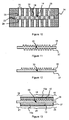
- the openings 25 of the cover 10 make the predetermined areas 33 accessible and control this hydrolysis step, to obtain a membrane 14 with the desired ion conduction characteristics ( figure 15 ).
- the resolution r 1 obtained is of the order of 0.1 mm.
- resolution is meant the smallest dimension r 1 of the pattern formed by the first or the second inactive region, respectively 23 and 24, of the membrane 14. This particular embodiment can be applied, preferably, for an elementary cell 9 having an active surface greater than or equal to 1 cm 2 .
- the three-dimensional configuration of the membrane 14 makes it possible to increase the developed contact surface between the first and second electrodes, 12 and 13, and the membrane 14 while maintaining the same projected area.
- the 3D configuration thus improves the power density of the fuel cell.
- the membrane 14 is initially constituted by an ionic conducting polymer 32 having sulfonic acid functional groups -SO 3 H, for example a National® polymer in the form of -SO 3 H.
- the non-conductive parts, 22 and 28, ionically and in particular the first and second inactive zones, 23 and 24, can be produced by forming non-conductive zones 31 ionically, by degradation of the sulfonic acid functional groups -SO 3 H of predetermined zones. 33 of the ionic conductive polymer 32.
- the degradation of the sulphonic acid functional groups -SO 3 H of the starting ionic conductive polymer 32 can be achieved by a conventional laser treatment or by a local heat treatment.
- an excimer laser emitting at a wavelength of 248 nm, with a pulse of 450 mJ / cm 2 can be used to degrade locally and in-depth the functions -SO 3 H of a layer 32 Nafion® conductive polymer in the form -SO 3 H, with a thickness of between 10 .mu.m and 200 .mu.m.
- the degradation is localized at predetermined zones 33 of the conducting polymer 32 Nafion® in the form -SO 3 H.
- the resolution r 2 obtained is of the order of 10 ⁇ m.
- This particular embodiment can be used, preferably, for an elementary cell 9 whose active surface is greater than or equal to 100 mm 2 .
- the membrane 14 is initially constituted by an ionic conductive polymer 32 having sulfonic acid functions.
- the first and second inactive zones, 23 and 24, that is, the non-conductive portion 22 and the optional non-conductive portion 28 may be made by creating non-conductive areas 31 ionically by conversion. of the sulfonic acid functional groups -SO 3 H of predetermined zones 33 of the ionic conductive polymer 32, in the function of sulfonyl halides -SO n X.
- a conductive polymer layer 32 Nafion® in the form of -SO 3 H is trapped in a press 34 so as to form a press / membrane assembly.
- the press 34 is provided with orifices 35 making it possible to expose predetermined zones 33 of the ionic conductive polymer 32.
- the conversion consists in treating only the predetermined zones 33 of the conducting polymer 32 Nafion® in the form -SO 3 H by chemical treatment.
- This step consists of immersing the press / membrane assembly successively in a first sodium hydroxide solution and then in a chemical etching solution.
- This etching solution consists of a mixture, advantageously, approximately equal weight of phosphorus pentachloride, PCl 5 , in the form of a powder and phosphoryl trichloride, POCl 3 , in liquid form.
- the press / membrane assembly is then heated in the solution - PCl 5 / POCl 3 at a temperature of between 100 ° C. and 130 ° C., preferably at 120 ° C., for several hours and then rinsed with POCl 3 and / or CCl 4 , to remove excess PCl 5 .
- the acid functional groups -SO 3 H of the conducting polymer 32 Nafion® are then converted chemically to sodium sulphonate, -SO 3 Na, then to sulphonyl chloride, -SO 2 Cl.
- the -SO 3 H functions are thus neutralized.
- the zones thus hydrolyzed are no longer ionically conductive since the sulfonyl chloride function can not ensure the transfer of the protons within the membrane 14.
- the parts protected by the press 34 then form the ionically conductive zones 29 of the membrane 14 and the exposed parts form the non-conductive zones 31 correspondingly ionically, according to the predetermined zones 33 chosen, to the non-conducting part 22 ionically and the additional non-conductive portion 28 of the finalized membrane 14.
- the press 34 allows negative masking with respect to the cover 10.
- the resolution r 3 obtained is of the order of 0.1 mm. This particular embodiment can be used, preferably, for an elementary cell 9 whose active surface is greater than or equal to 1 cm 2 .
- the membrane 14 then has the desired ionic conduction characteristics to achieve, according to the method described above, an elementary cell 9 having improved mechanical strength.
- the cover 10 is then arranged so that it envelopes the elementary cell 9 and that the openings 25 preferably expose the conductive zones 29 ionically without exposing the non-conductive zones 31 ionically.
- the fuel cell comprises a plurality of coplanar elementary cells 9 connected in series and enclosed in the cover 10.
- Such a multi-cell fuel cell can be produced according to methods identical to those described above except that the cover 10 envelops all the elementary cells 9.
- predetermined areas 33 must be chosen taking into account the number and position of the various elementary cells 9 of the fuel cell.
- the fuel cell advantageously has a "slide" type architecture in which the elementary cells 9 have the same membrane 14, which is unique and common to all the cells 9.
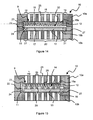
- the membrane 14 comprises at least one non-conductive portion 22 ionically delimiting each cell 9 and extending from the first inactive zone 23 to the second inactive zone 24, over the entire thickness of the membrane 14 ( figure 18 ).
- the adhesion means 27 are preferably constituted by an adhesive material making it possible to make the cover 10 integral with the elementary cells 9 and an electrically conductive material providing the electrical connection of the elementary cells 9 and putting them in series.
- the adhesion means 27 are arranged at least at the first and second inactive zones, 23 and 24, between the inner wall 11 and the membrane 14.
- the adhesion means 27 may, advantageously, form conductive tracks ensuring the series setting of the cells 9 of the fuel cell.
- the adhesion means 27 are formed by two distinct elements constituted, respectively, by the adhesive material 27a and the electrically conductive material 27b.
- the conductive tracks are, advantageously, made of electrically conductive material 27b and constituted by a first conductor track 27ba and a second conductive track 27bb.
- the first conductive track 27ba frames each of the first and second electrodes, 12 and 13, and is in direct contact with the sidewalls of the first and second electrodes, 12 and 13.
- the second conductive track 27bb is connected to the first track 27ba and connects the first electrode 12 of an elementary cell 9 to the second electrode 13 of an adjacent elementary cell 9.
- the adhesive material 27a may advantageously be disposed on the first and second uncovered portions, 19 and 21, which are not used by the conductive tracks, 27ba and 27bb.
- the first and second conductive tracks 27ba and 27bb can be directly integrated into the first and second covers, respectively 10a and 10b, according to any known method.
- the first and second tracks, 27ba and 27bb may, for example, be deposited by physical or chemical vapor deposition, denoted respectively as PVD or CVD, or by electrodeposition of the electrically conductive material 27b on the inner wall 11 of the cover 10.
- Figures 19 and 20 represent an open hood without the elementary cells 9 of a fuel cell according to the figure 18 .
- the second track 27bb is deposited so as to allow contact to be restored between the first electrode 12 of an elementary cell 9 in the "n" position and the second electrode 13 of an elementary cell 9 in the "n + 1" adjacent position.
- the second track 27bb starts from the first track 27ba intended to be in contact with the second electrode 13 of the elementary cell 9 in position "n", is extended along the inner wall 11 of the second cover 10b to the first cover 10a until the first track 27ba intended to be in contact with the first electrode 12 of the elementary cell 9 in position "n + 1" adjacent.
- the adhesion means 27 improve the mechanical strength of the fuel cell and the adhesive material 27a also avoids corrosion of the electrically conductive material 27b forming the conductive tracks, 27ba and 27bb.
- the adhesion means 27 are formed by a material having both adhesive properties and electrical conduction properties.
- the adhesion means 27 may, for example, be formed by a glue based on epoxy, silicone or polyurethane containing an electrically conductive material, for example a metallic material.
- the adhesion means 27 are arranged to form only conductive tracks ensuring both the electrical conduction and the adhesion of the elementary cells 9 to the wall 10.
- a fuel cell according to the invention has the advantage of being easy and quick to implement, while achieving high power densities. Moreover, the fuel cell has a very good mechanical strength, a good seal significantly improving the aging resistance of the battery.
Landscapes
- Life Sciences & Earth Sciences (AREA)
- Engineering & Computer Science (AREA)
- Manufacturing & Machinery (AREA)
- Sustainable Development (AREA)
- Sustainable Energy (AREA)
- Chemical & Material Sciences (AREA)
- Chemical Kinetics & Catalysis (AREA)
- Electrochemistry (AREA)
- General Chemical & Material Sciences (AREA)
- Fuel Cell (AREA)
Claims (13)
- Brennstoffzelle mit wenigstens einer Elementarzelle (9) und einer Kappe (10), die mit einer die Elementarcelle (9) umschließenden Innenwand (11) versehen ist, wobei die Zelle (9) mit einer ersten und einer zweiten Elektrode (12, 13) und mit einer Membran (14), welche einen Polymerelektrolyten umfasst, versehen ist, wobei die Membran (14) umfasst:- eine erste Hauptseite (16), die von einem durch die erste Elektrode (12) bedeckten ersten Teil (18) und einem durch die erste Elektrode (12) nicht bedeckten ersten Teil (19) gebildet ist, und- eine zweite Hauptseite (17), die von einem durch die zweite Elektrode (13) bedeckten zweiten Teil (20) und einem durch die zweite Elektrode (13) nicht bedeckten zweiten Teil (21) gebildet ist,dadurch gekennzeichnet, dass die Membran (14) umfasst:- einen ersten Teil aus einem Polymermaterial,- einen zweiten Teil, der durch Modifizieren der funktionellen Gruppen des Polymermaterials erhalten wird,wobei einer der Teile den Polymerelektrolyten bildet, wobei der andere Teil nicht elektrisch- und ionenleitend ist, der einen an dem nicht bedeckten ersten Teil (19, 21) gelegenen ersten inaktiven Bereich (23, 24) bildet,
und dass die Innenwand (11) der Kappe (10) an wenigstens dem ersten inaktiven Bereich (23, 24) durch Haftmittel (27), die gasdicht sind und den zwischen der Innenwand (11) der Kappe (10) und der Membran (14) ausgebildeten Raum auffüllen, mechanisch befestigt ist. - Brennstoffzelle nach Anspruch 1, dadurch gekennzeichnet, dass die Haftmittel (27) ein Haftmaterial umfassen.
- Brennstoffzelle nach Anspruch 2, dadurch gekennzeichnet, dass das Haftmaterial aus Zementen, Schweißmaterialien, Klebebändern und Klebstoffen oder Lacken auf Epoxid-, Silikon- oder Polyurethan-Basis ausgewählt ist.
- Brennstoffzelle nach einem der Ansprüche 1 bis 3, dadurch gekennzeichnet, dass die Haftmittel (27) ein elektrisch leitendes Material umfassen.
- Brennstoffzelle nach Anspruch 4, dadurch gekennzeichnet, dass das elektrisch leitende Material aus Kohlenstoff und Metallen, vorzugsweise Gold, Silber, Kupfer, Nickel, Aluminium und deren Legierungen ausgewählt ist.
- Brennstoffzelle nach einem der Ansprüche 1 bis 5, dadurch gekennzeichnet, dass der nicht ionenleitende Teil (22) sich von dem ersten inaktiven Bereich (23) bis zu einem an dem zweiten nicht bedeckten Teil (21) gelegenen zweiten inaktiven Bereich (24) über die gesamte Dicke der Membran (14) erstreckt.
- Brennstoffzelle nach einem der Ansprüche 1 bis 6, dadurch gekennzeichnet, dass sie einen zusätzlichen nicht leitenden Teil (28) umfasst, der ein Netz aus zusätzlichen inaktiven Bereichen innerhalb der Membran (14) bildet.
- Brennstoffzelle nach einem der Ansprüche 1 bis 7, dadurch gekennzeichnet, dass sie mehrere koplanare Elementarzellen (9), die in Reihe geschaltet und in der Kappe (10) eingeschlossen sind, umfasst und dass die Elementarzellen (9) eine einzige und allen Zellen (9) gemeinsame gleiche Membran (14) haben, wobei die Membran (14) wenigstens einen nicht ionenleitenden Teil (22) umfasst, der jede Zelle (9) begrenzt und der sich von dem ersten inaktiven Bereich (23) bis zu einem an dem zweiten nicht bedeckten Teil (21) gelegenen zweiten inaktiven Bereich (24) über die gesamte Dicke der Membran (14) erstreckt.
- Brennstoffzelle nach Anspruch 8, dadurch gekennzeichnet, dass die Haftmittel (27) Leiterbahnen bilden, die gebildet sind von:- einer ersten Leiterbahn (27ba), die eine jede der ersten und zweiten Elektroden (12, 13) umrahmt und in direktem Kontakt mit den Seitenwänden der ersten und der zweiten Elektrode (12, 13) ist, und- einer zweiten Leiterbahn (27bb), die mit der ersten Leiterbahn (27ba) verbunden ist und die erste Elektrode (12) einer Elementarzelle (9) mit der zweiten Elektrode (13) einer benachbarten Elementarzelle (9) verbindet.
- Verfahren zur Herstellung einer Brennstoffzelle nach einem der Ansprüche 1 bis 9, dadurch gekennzeichnet, dass es die Schritte umfasst des:- Ausbildens des ersten und des zweiten inaktiven Bereichs (23, 24) auf einer ersten bzw. einer zweiten Hauptseite (16, 17) einer von einem ionenleitenden Polymerelektrolyten gebildeten Membran (14), und des- Befestigens einer Kappe (10) an der Membran (14) durch Haftmittel (27), die zwischen dem ersten inaktiven Bereich (23) und der Innenwand (11) der Kappe (10) und/oder dem zweiten inaktiven Bereich (24) und der Innenwand (11) der Kappe (10) angeordnet sind.
- Verfahren nach Anspruch 10, dadurch gekennzeichnet, dass die Membran (14) anfangs von einem nicht ionenleitenden Polymer (30) mit Sulfonylhalogenidfunktionen gebildet ist, und der erste und der zweite inaktive Bereich (23, 24) dadurch ausgebildet werden, dass ionenleitende Bereiche (29) durch Hydrolyse der Sulfonylhalogenidfunktionen von vorbestimmten Bereichen (33) des Polymers (30) gebildet werden.
- Verfahren nach Anspruch 10, dadurch gekennzeichnet, dass die Membran (14) anfangs von einem ionenleitenden Polymer (32) mit Sulfonsäurefunktionen gebildet ist, und der erste und der zweite inaktive Bereich (23, 24) dadurch ausgebildet werden, dass nicht ionenleitende Bereiche (31) durch Abbau der Sulfonsäurefunktionen von vorbestimmten Bereichen (33) des Polymers (32) gebildet werden.
- Verfahren nach Anspruch 10, dadurch gekennzeichnet, dass die Membran (14) anfangs von einem ionenleitenden Polymer (32) mit Sulfonsäurefunktionen gebildet ist, und der erste und der zweite inaktive Bereich (23, 24) dadurch ausgebildet werden, dass nicht ionenleitende Bereiche (31) durch chemische Umwandlung der Sulfonsäurefunktionen von vorbestimmten Bereichen (33) des Polymers (32) in Sulfonylhalogenidfunktionen erzeugt werden.
Applications Claiming Priority (2)
| Application Number | Priority Date | Filing Date | Title |
|---|---|---|---|
| FR1001436A FR2958798B1 (fr) | 2010-04-07 | 2010-04-07 | Pile a combustible comportant une membrane a conduction ionique localisee et procede de fabrication. |
| PCT/FR2011/000156 WO2011124778A1 (fr) | 2010-04-07 | 2011-03-21 | Pile à combustible comportant une membrane à conduction ionique localisée et procédé de fabrication |
Publications (2)
| Publication Number | Publication Date |
|---|---|
| EP2556554A1 EP2556554A1 (de) | 2013-02-13 |
| EP2556554B1 true EP2556554B1 (de) | 2014-04-02 |
Family
ID=42357747
Family Applications (1)
| Application Number | Title | Priority Date | Filing Date |
|---|---|---|---|
| EP11730337.0A Not-in-force EP2556554B1 (de) | 2010-04-07 | 2011-03-21 | Brennstoffzelle mit einer membran mit lokalisierter ionenleitung und verfahren zu dessen herstellung |
Country Status (5)
| Country | Link |
|---|---|
| US (1) | US20130059225A1 (de) |
| EP (1) | EP2556554B1 (de) |
| ES (1) | ES2459740T3 (de) |
| FR (1) | FR2958798B1 (de) |
| WO (1) | WO2011124778A1 (de) |
Families Citing this family (4)
| Publication number | Priority date | Publication date | Assignee | Title |
|---|---|---|---|---|
| US10193169B2 (en) | 2013-03-15 | 2019-01-29 | Intelligent Energy Limited | Fluidic interface module for a fuel cell system |
| US9680171B2 (en) | 2013-03-15 | 2017-06-13 | Intelligent Energy Limited | Methods for operating a fuel cell system |
| US9577273B2 (en) | 2013-03-15 | 2017-02-21 | Intelligent Energy Limited | Fluidic interface module for a fuel cell system |
| US20140272645A1 (en) | 2013-03-15 | 2014-09-18 | SOCIéTé BIC | Fuel cell dc-dc converter |
Family Cites Families (13)
| Publication number | Priority date | Publication date | Assignee | Title |
|---|---|---|---|---|
| JPH09501007A (ja) * | 1993-07-28 | 1997-01-28 | フラウンホーファー‐ゲゼルシャフト ツール フェルデルング デア アンゲヴァンテン フォルシュング エー.ファウ. | 複数のセルを含む細片膜状の電池 |
| DE19624887A1 (de) * | 1995-06-21 | 1997-01-02 | Fraunhofer Ges Forschung | Elektrochemisches Festelektrolyt-Zellsystem |
| US6127058A (en) * | 1998-10-30 | 2000-10-03 | Motorola, Inc. | Planar fuel cell |
| US20020022382A1 (en) * | 2000-08-18 | 2002-02-21 | Franklin Jerrold E. | Compliant electrical contacts for fuel cell use |
| FR2819108B1 (fr) * | 2000-12-29 | 2003-01-31 | Commissariat Energie Atomique | Element de base composite et son joint pour pile a combustible et procede de fabrication de l'ensemble |
| FR2819107B1 (fr) | 2000-12-29 | 2003-09-05 | Commissariat Energie Atomique | Procede de fabrication d'un assemblage d'elements de base pour un etage de pile a combustible |
| DE10224452C1 (de) * | 2002-05-29 | 2003-11-20 | Fraunhofer Ges Forschung | Protonenleitende Polymermembran sowie Verfahren zu deren Herstellung |
| FR2852736B1 (fr) | 2003-03-18 | 2005-04-22 | Pile a combustible planaire et procede de fabrication d'une telle pile. | |
| JP4956882B2 (ja) * | 2003-07-22 | 2012-06-20 | トヨタ自動車株式会社 | 燃料電池 |
| DE112004001357T5 (de) * | 2003-07-22 | 2006-07-20 | E.I. Dupont De Nemours And Co., Wilmington | Verfahren zum Herstellen planarer, mit Rahmen versehener Membranelektrodenbaugruppen-Arrays und diese enthaltende Brennstoffzellen |
| EP1727228A1 (de) * | 2005-05-24 | 2006-11-29 | Samsung SDI Co., Ltd. | Monpolare Membran-Elektroden Einheit |
| JP4992207B2 (ja) * | 2005-07-19 | 2012-08-08 | トヨタ自動車株式会社 | 複合多孔質膜、複合多孔質膜の製造方法、固体高分子電解質膜、及び燃料電池 |
| FR2894720B1 (fr) * | 2005-12-09 | 2010-12-10 | Commissariat Energie Atomique | Pile a combustible avec collecteurs de courant integres a l'electrolyte solide et procede de fabrication d'une telle pile a combustible. |
-
2010
- 2010-04-07 FR FR1001436A patent/FR2958798B1/fr not_active Expired - Fee Related
-
2011
- 2011-03-21 WO PCT/FR2011/000156 patent/WO2011124778A1/fr not_active Ceased
- 2011-03-21 US US13/640,273 patent/US20130059225A1/en not_active Abandoned
- 2011-03-21 ES ES11730337.0T patent/ES2459740T3/es active Active
- 2011-03-21 EP EP11730337.0A patent/EP2556554B1/de not_active Not-in-force
Also Published As
| Publication number | Publication date |
|---|---|
| US20130059225A1 (en) | 2013-03-07 |
| EP2556554A1 (de) | 2013-02-13 |
| ES2459740T3 (es) | 2014-05-12 |
| WO2011124778A1 (fr) | 2011-10-13 |
| FR2958798B1 (fr) | 2015-04-03 |
| FR2958798A1 (fr) | 2011-10-14 |
Similar Documents
| Publication | Publication Date | Title |
|---|---|---|
| EP2061114B1 (de) | Brennstoffzelle, bestehend aus mehreren Elementarzellen, die durch Serienschaltung mit den Stromkollektoren miteinander verbunden sind | |
| TWI360249B (en) | Lithium oxygen batteries and method of producing s | |
| EP1915797B1 (de) | Polymerverbundmembran mit ionen-/elektronenleitfähigkeit, herstellungsverfahren dafür und kern einer planaren brennstoffzelle mit dieser membran | |
| EP1604420A1 (de) | Planare brennstoffzelle und verfahren zu deren herstellung | |
| CA3063286A1 (fr) | Reacteur d'electrolyse ou de co-electrolyse de l'eau (soec) ou pile a combustible (sofc) a fonctionnement sous pression et a systeme de serrage adapte a un tel fonctionnement | |
| EP2556554A1 (de) | Brennstoffzelle mit einer membran mit lokalisierter ionenleitung und verfahren zu dessen herstellung | |
| FR3096927A1 (fr) | Film conducteur composite pour la réalisation d'accumulateurs d'énergie électrique, procédé de réalisation d'un tel film, et accumulateur électrique utilisant un tel film. | |
| FR2550015A1 (fr) | Generateur electrochimique en couche mince comportant une electrode positive electrodeposee | |
| FR3002482A1 (fr) | Procede de realisation de couches minces structurees en 3d | |
| FR2819108A1 (fr) | Element de base composite et son joint pour pile a combustible et procede de fabrication de l'ensemble | |
| FR3069107A1 (fr) | Plaque de maintien de cellule electrochimique a etancheite amelioree | |
| FR2838870A1 (fr) | Element de base de pile a combustible limitant la traversee de l'electrolyte par le methanol | |
| EP2301101B1 (de) | Brennstoffzelle mit einem zu dem trägersubstrat senkrechten membran-/elektrodenstapel und herstellungsprozess | |
| EP1964203B1 (de) | Verfahren zur herstellung einer brennstoffzelle mit im festelektrolyt integrierten stromkollektoren | |
| FR2846797A1 (fr) | Module de base monobloc et a relief de pile a combustible miniature et son procede de fabrication | |
| EP2867947B1 (de) | Verfahren zur herstellung einer elektroden-/protonenaustauschmembrananordnung | |
| FR2918799A1 (fr) | Substrat poreux etanche pour piles a combustible planaires et packaging integre. | |
| KR100925251B1 (ko) | 연료전지 | |
| FR2963483A1 (fr) | Pile a combustible comportant une pluralite de cellules elementaires connectees en serie et son procede de realisation | |
| WO2023118155A1 (fr) | Electrode à air et son procédé de fabrication | |
| FR3157971A1 (fr) | Plaque de séparation d’interconnecteur à bord plié et empilement associé | |
| FR3128059A1 (fr) | Batterie à électrolyte solide | |
| WO2013041781A1 (fr) | Pile à combustible à haute densité d'assemblages membrane-électrodes partageant une cavité fluidique commune |
Legal Events
| Date | Code | Title | Description |
|---|---|---|---|
| PUAI | Public reference made under article 153(3) epc to a published international application that has entered the european phase |
Free format text: ORIGINAL CODE: 0009012 |
|
| 17P | Request for examination filed |
Effective date: 20121009 |
|
| AK | Designated contracting states |
Kind code of ref document: A1 Designated state(s): AL AT BE BG CH CY CZ DE DK EE ES FI FR GB GR HR HU IE IS IT LI LT LU LV MC MK MT NL NO PL PT RO RS SE SI SK SM TR |
|
| DAX | Request for extension of the european patent (deleted) | ||
| GRAP | Despatch of communication of intention to grant a patent |
Free format text: ORIGINAL CODE: EPIDOSNIGR1 |
|
| INTG | Intention to grant announced |
Effective date: 20131028 |
|
| GRAS | Grant fee paid |
Free format text: ORIGINAL CODE: EPIDOSNIGR3 |
|
| GRAA | (expected) grant |
Free format text: ORIGINAL CODE: 0009210 |
|
| AK | Designated contracting states |
Kind code of ref document: B1 Designated state(s): AL AT BE BG CH CY CZ DE DK EE ES FI FR GB GR HR HU IE IS IT LI LT LU LV MC MK MT NL NO PL PT RO RS SE SI SK SM TR |
|
| REG | Reference to a national code |
Ref country code: GB Ref legal event code: FG4D Free format text: NOT ENGLISH |
|
| REG | Reference to a national code |
Ref country code: CH Ref legal event code: EP Ref country code: AT Ref legal event code: REF Ref document number: 660620 Country of ref document: AT Kind code of ref document: T Effective date: 20140415 |
|
| REG | Reference to a national code |
Ref country code: IE Ref legal event code: FG4D Free format text: LANGUAGE OF EP DOCUMENT: FRENCH |
|
| REG | Reference to a national code |
Ref country code: DE Ref legal event code: R096 Ref document number: 602011005950 Country of ref document: DE Effective date: 20140508 |
|
| REG | Reference to a national code |
Ref country code: ES Ref legal event code: FG2A Ref document number: 2459740 Country of ref document: ES Kind code of ref document: T3 Effective date: 20140512 |
|
| REG | Reference to a national code |
Ref country code: AT Ref legal event code: MK05 Ref document number: 660620 Country of ref document: AT Kind code of ref document: T Effective date: 20140402 |
|
| REG | Reference to a national code |
Ref country code: NL Ref legal event code: VDEP Effective date: 20140402 |
|
| REG | Reference to a national code |
Ref country code: LT Ref legal event code: MG4D |
|
| PG25 | Lapsed in a contracting state [announced via postgrant information from national office to epo] |
Ref country code: GR Free format text: LAPSE BECAUSE OF FAILURE TO SUBMIT A TRANSLATION OF THE DESCRIPTION OR TO PAY THE FEE WITHIN THE PRESCRIBED TIME-LIMIT Effective date: 20140703 Ref country code: BG Free format text: LAPSE BECAUSE OF FAILURE TO SUBMIT A TRANSLATION OF THE DESCRIPTION OR TO PAY THE FEE WITHIN THE PRESCRIBED TIME-LIMIT Effective date: 20140702 Ref country code: FI Free format text: LAPSE BECAUSE OF FAILURE TO SUBMIT A TRANSLATION OF THE DESCRIPTION OR TO PAY THE FEE WITHIN THE PRESCRIBED TIME-LIMIT Effective date: 20140402 Ref country code: CY Free format text: LAPSE BECAUSE OF FAILURE TO SUBMIT A TRANSLATION OF THE DESCRIPTION OR TO PAY THE FEE WITHIN THE PRESCRIBED TIME-LIMIT Effective date: 20140402 Ref country code: LT Free format text: LAPSE BECAUSE OF FAILURE TO SUBMIT A TRANSLATION OF THE DESCRIPTION OR TO PAY THE FEE WITHIN THE PRESCRIBED TIME-LIMIT Effective date: 20140402 Ref country code: NO Free format text: LAPSE BECAUSE OF FAILURE TO SUBMIT A TRANSLATION OF THE DESCRIPTION OR TO PAY THE FEE WITHIN THE PRESCRIBED TIME-LIMIT Effective date: 20140702 Ref country code: IS Free format text: LAPSE BECAUSE OF FAILURE TO SUBMIT A TRANSLATION OF THE DESCRIPTION OR TO PAY THE FEE WITHIN THE PRESCRIBED TIME-LIMIT Effective date: 20140802 Ref country code: CZ Free format text: LAPSE BECAUSE OF FAILURE TO SUBMIT A TRANSLATION OF THE DESCRIPTION OR TO PAY THE FEE WITHIN THE PRESCRIBED TIME-LIMIT Effective date: 20140402 Ref country code: NL Free format text: LAPSE BECAUSE OF FAILURE TO SUBMIT A TRANSLATION OF THE DESCRIPTION OR TO PAY THE FEE WITHIN THE PRESCRIBED TIME-LIMIT Effective date: 20140402 |
|
| PG25 | Lapsed in a contracting state [announced via postgrant information from national office to epo] |
Ref country code: LV Free format text: LAPSE BECAUSE OF FAILURE TO SUBMIT A TRANSLATION OF THE DESCRIPTION OR TO PAY THE FEE WITHIN THE PRESCRIBED TIME-LIMIT Effective date: 20140402 Ref country code: SE Free format text: LAPSE BECAUSE OF FAILURE TO SUBMIT A TRANSLATION OF THE DESCRIPTION OR TO PAY THE FEE WITHIN THE PRESCRIBED TIME-LIMIT Effective date: 20140402 Ref country code: HR Free format text: LAPSE BECAUSE OF FAILURE TO SUBMIT A TRANSLATION OF THE DESCRIPTION OR TO PAY THE FEE WITHIN THE PRESCRIBED TIME-LIMIT Effective date: 20140402 Ref country code: RS Free format text: LAPSE BECAUSE OF FAILURE TO SUBMIT A TRANSLATION OF THE DESCRIPTION OR TO PAY THE FEE WITHIN THE PRESCRIBED TIME-LIMIT Effective date: 20140402 Ref country code: PL Free format text: LAPSE BECAUSE OF FAILURE TO SUBMIT A TRANSLATION OF THE DESCRIPTION OR TO PAY THE FEE WITHIN THE PRESCRIBED TIME-LIMIT Effective date: 20140402 Ref country code: AT Free format text: LAPSE BECAUSE OF FAILURE TO SUBMIT A TRANSLATION OF THE DESCRIPTION OR TO PAY THE FEE WITHIN THE PRESCRIBED TIME-LIMIT Effective date: 20140402 |
|
| PG25 | Lapsed in a contracting state [announced via postgrant information from national office to epo] |
Ref country code: PT Free format text: LAPSE BECAUSE OF FAILURE TO SUBMIT A TRANSLATION OF THE DESCRIPTION OR TO PAY THE FEE WITHIN THE PRESCRIBED TIME-LIMIT Effective date: 20140804 |
|
| REG | Reference to a national code |
Ref country code: DE Ref legal event code: R097 Ref document number: 602011005950 Country of ref document: DE |
|
| PG25 | Lapsed in a contracting state [announced via postgrant information from national office to epo] |
Ref country code: DK Free format text: LAPSE BECAUSE OF FAILURE TO SUBMIT A TRANSLATION OF THE DESCRIPTION OR TO PAY THE FEE WITHIN THE PRESCRIBED TIME-LIMIT Effective date: 20140402 Ref country code: RO Free format text: LAPSE BECAUSE OF FAILURE TO SUBMIT A TRANSLATION OF THE DESCRIPTION OR TO PAY THE FEE WITHIN THE PRESCRIBED TIME-LIMIT Effective date: 20140402 Ref country code: EE Free format text: LAPSE BECAUSE OF FAILURE TO SUBMIT A TRANSLATION OF THE DESCRIPTION OR TO PAY THE FEE WITHIN THE PRESCRIBED TIME-LIMIT Effective date: 20140402 Ref country code: SK Free format text: LAPSE BECAUSE OF FAILURE TO SUBMIT A TRANSLATION OF THE DESCRIPTION OR TO PAY THE FEE WITHIN THE PRESCRIBED TIME-LIMIT Effective date: 20140402 |
|
| PLBE | No opposition filed within time limit |
Free format text: ORIGINAL CODE: 0009261 |
|
| STAA | Information on the status of an ep patent application or granted ep patent |
Free format text: STATUS: NO OPPOSITION FILED WITHIN TIME LIMIT |
|
| 26N | No opposition filed |
Effective date: 20150106 |
|
| REG | Reference to a national code |
Ref country code: DE Ref legal event code: R097 Ref document number: 602011005950 Country of ref document: DE Effective date: 20150106 |
|
| PGFP | Annual fee paid to national office [announced via postgrant information from national office to epo] |
Ref country code: ES Payment date: 20150324 Year of fee payment: 5 Ref country code: IT Payment date: 20150325 Year of fee payment: 5 |
|
| PG25 | Lapsed in a contracting state [announced via postgrant information from national office to epo] |
Ref country code: RS Free format text: LAPSE BECAUSE OF FAILURE TO SUBMIT A TRANSLATION OF THE DESCRIPTION OR TO PAY THE FEE WITHIN THE PRESCRIBED TIME-LIMIT Effective date: 20141119 |
|
| PG25 | Lapsed in a contracting state [announced via postgrant information from national office to epo] |
Ref country code: SI Free format text: LAPSE BECAUSE OF FAILURE TO SUBMIT A TRANSLATION OF THE DESCRIPTION OR TO PAY THE FEE WITHIN THE PRESCRIBED TIME-LIMIT Effective date: 20140402 |
|
| PG25 | Lapsed in a contracting state [announced via postgrant information from national office to epo] |
Ref country code: LU Free format text: LAPSE BECAUSE OF FAILURE TO SUBMIT A TRANSLATION OF THE DESCRIPTION OR TO PAY THE FEE WITHIN THE PRESCRIBED TIME-LIMIT Effective date: 20150321 Ref country code: MC Free format text: LAPSE BECAUSE OF FAILURE TO SUBMIT A TRANSLATION OF THE DESCRIPTION OR TO PAY THE FEE WITHIN THE PRESCRIBED TIME-LIMIT Effective date: 20140402 |
|
| REG | Reference to a national code |
Ref country code: CH Ref legal event code: PL |
|
| REG | Reference to a national code |
Ref country code: IE Ref legal event code: MM4A |
|
| PG25 | Lapsed in a contracting state [announced via postgrant information from national office to epo] |
Ref country code: LI Free format text: LAPSE BECAUSE OF NON-PAYMENT OF DUE FEES Effective date: 20150331 Ref country code: IE Free format text: LAPSE BECAUSE OF NON-PAYMENT OF DUE FEES Effective date: 20150321 Ref country code: CH Free format text: LAPSE BECAUSE OF NON-PAYMENT OF DUE FEES Effective date: 20150331 |
|
| REG | Reference to a national code |
Ref country code: FR Ref legal event code: PLFP Year of fee payment: 6 |
|
| PG25 | Lapsed in a contracting state [announced via postgrant information from national office to epo] |
Ref country code: MT Free format text: LAPSE BECAUSE OF FAILURE TO SUBMIT A TRANSLATION OF THE DESCRIPTION OR TO PAY THE FEE WITHIN THE PRESCRIBED TIME-LIMIT Effective date: 20140402 |
|
| PG25 | Lapsed in a contracting state [announced via postgrant information from national office to epo] |
Ref country code: IT Free format text: LAPSE BECAUSE OF NON-PAYMENT OF DUE FEES Effective date: 20160321 |
|
| REG | Reference to a national code |
Ref country code: FR Ref legal event code: PLFP Year of fee payment: 7 |
|
| REG | Reference to a national code |
Ref country code: ES Ref legal event code: FD2A Effective date: 20170428 |
|
| PG25 | Lapsed in a contracting state [announced via postgrant information from national office to epo] |
Ref country code: SM Free format text: LAPSE BECAUSE OF FAILURE TO SUBMIT A TRANSLATION OF THE DESCRIPTION OR TO PAY THE FEE WITHIN THE PRESCRIBED TIME-LIMIT Effective date: 20140402 Ref country code: HU Free format text: LAPSE BECAUSE OF FAILURE TO SUBMIT A TRANSLATION OF THE DESCRIPTION OR TO PAY THE FEE WITHIN THE PRESCRIBED TIME-LIMIT; INVALID AB INITIO Effective date: 20110321 |
|
| PG25 | Lapsed in a contracting state [announced via postgrant information from national office to epo] |
Ref country code: BE Free format text: LAPSE BECAUSE OF NON-PAYMENT OF DUE FEES Effective date: 20150331 |
|
| PG25 | Lapsed in a contracting state [announced via postgrant information from national office to epo] |
Ref country code: ES Free format text: LAPSE BECAUSE OF NON-PAYMENT OF DUE FEES Effective date: 20160322 Ref country code: TR Free format text: LAPSE BECAUSE OF FAILURE TO SUBMIT A TRANSLATION OF THE DESCRIPTION OR TO PAY THE FEE WITHIN THE PRESCRIBED TIME-LIMIT Effective date: 20140402 |
|
| REG | Reference to a national code |
Ref country code: FR Ref legal event code: PLFP Year of fee payment: 8 |
|
| PGFP | Annual fee paid to national office [announced via postgrant information from national office to epo] |
Ref country code: GB Payment date: 20180316 Year of fee payment: 8 Ref country code: DE Payment date: 20180309 Year of fee payment: 8 |
|
| PGFP | Annual fee paid to national office [announced via postgrant information from national office to epo] |
Ref country code: FR Payment date: 20180329 Year of fee payment: 8 |
|
| PG25 | Lapsed in a contracting state [announced via postgrant information from national office to epo] |
Ref country code: MK Free format text: LAPSE BECAUSE OF FAILURE TO SUBMIT A TRANSLATION OF THE DESCRIPTION OR TO PAY THE FEE WITHIN THE PRESCRIBED TIME-LIMIT Effective date: 20140402 |
|
| PG25 | Lapsed in a contracting state [announced via postgrant information from national office to epo] |
Ref country code: AL Free format text: LAPSE BECAUSE OF FAILURE TO SUBMIT A TRANSLATION OF THE DESCRIPTION OR TO PAY THE FEE WITHIN THE PRESCRIBED TIME-LIMIT Effective date: 20140402 |
|
| REG | Reference to a national code |
Ref country code: DE Ref legal event code: R119 Ref document number: 602011005950 Country of ref document: DE |
|
| GBPC | Gb: european patent ceased through non-payment of renewal fee |
Effective date: 20190321 |
|
| PG25 | Lapsed in a contracting state [announced via postgrant information from national office to epo] |
Ref country code: DE Free format text: LAPSE BECAUSE OF NON-PAYMENT OF DUE FEES Effective date: 20191001 Ref country code: GB Free format text: LAPSE BECAUSE OF NON-PAYMENT OF DUE FEES Effective date: 20190321 |
|
| PG25 | Lapsed in a contracting state [announced via postgrant information from national office to epo] |
Ref country code: FR Free format text: LAPSE BECAUSE OF NON-PAYMENT OF DUE FEES Effective date: 20190331 |