EP2555359A2 - Gehäuse zum Montieren einer elektrischen Vorrichtung - Google Patents
Gehäuse zum Montieren einer elektrischen Vorrichtung Download PDFInfo
- Publication number
- EP2555359A2 EP2555359A2 EP12179281A EP12179281A EP2555359A2 EP 2555359 A2 EP2555359 A2 EP 2555359A2 EP 12179281 A EP12179281 A EP 12179281A EP 12179281 A EP12179281 A EP 12179281A EP 2555359 A2 EP2555359 A2 EP 2555359A2
- Authority
- EP
- European Patent Office
- Prior art keywords
- lower housing
- housing
- bracket
- band
- mounting
- Prior art date
- Legal status (The legal status is an assumption and is not a legal conclusion. Google has not performed a legal analysis and makes no representation as to the accuracy of the status listed.)
- Granted
Links
Images


Classifications
-
- H—ELECTRICITY
- H02—GENERATION; CONVERSION OR DISTRIBUTION OF ELECTRIC POWER
- H02B—BOARDS, SUBSTATIONS OR SWITCHING ARRANGEMENTS FOR THE SUPPLY OR DISTRIBUTION OF ELECTRIC POWER
- H02B5/00—Non-enclosed substations; Substations with enclosed and non-enclosed equipment
- H02B5/02—Non-enclosed substations; Substations with enclosed and non-enclosed equipment mounted on pole, e.g. pole transformer substation
-
- H—ELECTRICITY
- H05—ELECTRIC TECHNIQUES NOT OTHERWISE PROVIDED FOR
- H05K—PRINTED CIRCUITS; CASINGS OR CONSTRUCTIONAL DETAILS OF ELECTRIC APPARATUS; MANUFACTURE OF ASSEMBLAGES OF ELECTRICAL COMPONENTS
- H05K5/00—Casings, cabinets or drawers for electric apparatus
Definitions
- the present invention relates to a rotatable lower housing for a high voltage electrical circuit or other high voltage electrical device. More particularly, the present invention relates to a cylindrically-shaped lower housing which is rotatable, a bracket for mounting the lower housing onto a support structure, and a surrounding element which allows the lower housing to be rotatable with respect to the bracket.
- the present invention provides a rotatable lower housing for a high voltage electrical circuit or other high voltage electrical device which allows a utility installer to rotate the high voltage electrical device so that it is in proper alignment with the connecting electrical equipment.
- the invention comprises a lower housing which is rotatable.
- a bracket is provided for mounting the rotatable lower housing to a utility structure.
- Three embodiments are provided which allow for the lower housing to be rotatable with respect to the bracket.
- the term "rotatable" is considered to be any rotation of at least 5 degrees of the lower housing.
- the first preferred embodiment comprises a one-piece surrounding mounting bracket that completely surrounds the lower housing, allowing the lower housing to be rotatable within the one-piece surrounding mounting bracket.
- the mounting bracket may be made of a metallic material or a plastic material such as a high-strength plastic material.
- a suitable high-strength plastic material is a thermoformed plastic material; that is, a plastic which has been manufactured using a thermoforming process.
- the plastic may be a thermosetting plastic material.
- any plastic may be used.
- the second embodiment comprises an adjustable upper band and an adjustable lower band that completely surround the lower housing and which are attached to a mounting bracket.
- the bracket, the upper band and the lower band may be made of a metallic material.
- the bracket, the upper band and the lower band may be made of a high-strength plastic material.
- the third embodiment comprises an integral surrounding I-slot which completely surrounds the lower housing and which allows for a bracket to be non-fixedly seated within the slot.
- the bracket for mounting may be made of a metallic material.
- the bracket for mounting may be made of a high-strength plastic material.
- the bracket is slidably seated within the upper channel and the lower channel of the I-slot by tabs which connect to and protrude from the parallel side walls of the bracket and which are opposite from the rear wall of the bracket and wherein the tabs non-fixedly abut a surface of the rotatable lower housing.
- at least one of the tabs contains an aperture for receiving a fastener for selectively preventing the lower housing from rotating with respect to the bracket.
- the fastener is a screw which can be loosened so that the lower housing can be freely rotated or tightened so that the lower housing can be in a fixed position.
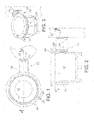
- FIG. 1 is a plan view of a rotatable lower housing and a one-piece surrounding mounting bracket for a high voltage electrical device of the present invention taken along section B-B of FIG. 2 .
- FIG. 2 is cross-sectional elevation view of a rotatable lower housing and a one-piece surrounding mounting bracket for a high voltage electrical device of the present invention taken along section C-C of FIG. 1 .
- FIG. 3 is a front perspective view of a rotatable lower housing and a one-piece surrounding mounting bracket for a high voltage electrical device of the present invention.
- FIG. 4 is a plan view of a rotatable lower housing with upper and lower bands connected to a bracket for a high voltage electrical device of the present invention taken along section B-B of FIG. 5 .
- FIG. 5 is a side elevation view of a rotatable lower housing with upper and lower bands connected to a bracket for a high voltage electrical device of the present invention.
- FIG. 6 is a front perspective view of a rotatable lower housing with upper and lower bands connected to a bracket for a high voltage electrical device of the present invention.
- FIG. 7 is a plan view of a rotatable lower housing with an integral surrounding I-slot for a high voltage electrical device of the present invention taken along section B-B of FIG. 8 .
- FIG. 8 is cross-sectional elevation view of a rotatable lower housing with an integral surrounding I-slot for a high voltage electrical device of the present invention taken along section A-A of FIG. 7 .
- FIG. 9 is a front perspective view of a rotatable lower housing with an integral surrounding I-slot for a high voltage electrical device of the present invention.
- FIG. 1 Shown in FIG. 1 is a plan view of a first preferred embodiment of the present invention, which is a rotatable lower housing 10 for a single phase recloser of a high voltage electrical circuit or another high voltage electrical device.
- the lower housing may be made of a corrosion-resistant metal, such as stainless steel, or a high-strength plastic.
- the housing may also be painted with a UV and/or corrosion-resistant paint for further protection from the environment.
- FIG. 1 shows the cylindrical rotatable lower housing 10 being completely surrounded by a one-piece surrounding mounting bracket 12.
- the one-piece surrounding mounting bracket 12 comprises a ring 14 which completely surrounds the lower housing 10.
- At least two parallel side walls 16 are shown protruding from the ring 14, and a rear wall 18 is shown which connects the two side walls 16 and is perpendicular to the side walls 16.
- the rear wall 18 allows the one piece surrounding mounting bracket 12 to be mounted to a support structure 13, such as a utility or distribution pole, by hardware such as bolts or screws which are received by at least one aperture 11 in the rear wall 18 to attach the rear wall 18 to the support structure 13.
- a support structure 13 such as a utility or distribution pole
- it may be a precast component which is made of a metallic or high-strength plastic material. It may also be formed of a weather resistant steel such as stainless steel or galvanized steel.
- an anti-rotation fastener 20 is received through an aperture 22 that is contained within the ring 14.
- the anti-rotation fastener 20 may, for example, be a screw which can be loosened or tightened within the aperture 22 that is contained in the ring 14 such that when tightened, the screw contacts the rotatable lower housing 10, thereby preventing rotation of the housing 10.
- the anti-rotation fastener 20 can be loosened such that it does not contact the lower housing 10, thereby allowing the lower housing 10 to freely rotate within the ring 14 of the one-piece surrounding mounting bracket 12.
- FIG. 1 only one anti-rotation fastener 20 is shown, however, it is understood that more than one anti-rotation fastener may be used at multiple locations on the ring 14 of the surrounding mounting bracket 12.
- FIG. 2 Shown in FIG. 2 is a cross-sectional elevation view of the first preferred embodiment of the present invention.
- a radial flange 26 of the rotatable lower housing 10 is shown, and a lip 24 of the radial flange 26 is also shown.
- the lip 24 and the radial flange 26 are integrally formed with the rotatable lower housing 10. The presence of the lip 24 prevents downward vertical movement of the rotatable lower housing 10 through the one-piece surrounding mounting bracket 12 when the lip 24 is in contact with the one-piece surrounding mounting bracket 12.
- FIG. 3 shows a front perspective view of the first preferred embodiment of the present invention and again shows each of the elements previously discussed in FIGS. 1 and 2 .
- FIG. 5 is a side elevation view of a cylindrical rotatable lower housing 10 with upper and lower bands 28 and 30 which completely surround the lower housing 10.
- the bands 28 and 30 may be made of a corrosion resistant metallic material or a high-strength plastic.
- Each of the bands has a band adjustment mechanism 34 located on the respective bands.
- the band adjustment mechanism 34 allows for adjustment of tension within the bands 28 and 30 such that the bands may be tightened or loosened around the lower housing 10.
- a bracket 32 comprising two parallel side walls 16 and a rear wall 18 which is perpendicular to the side walls 16, is affixed to the bands 28 and 30.
- the rear wall 18 allows the bracket 32 to be mounted to a support structure 13, such as a utility or distribution pole, by hardware such as bolts or screws which are received by at least one aperture 11 in the rear wall 18 to attach the rear wall 18 to the support structure 13.
- a support structure 13 such as a utility or distribution pole
- the bracket 32 may be made of a corrosion resistant metallic material or a high-strength plastic.
- the bracket 32 is shown to be affixed to the bands 28 and 30 by tabs 36 which are connected to and protrude from the side walls 16 of the bracket 32.
- the tabs 36 non-fixedly abut a surface 38 of the lower housing 10 so that the housing 10 may freely rotate within the bands 28 and 30.
- the tabs 36 may be affixed to the bracket 32 and the bands 28 and 30 by welding, such that the tabs 36, bracket 32 and bands 28 and 30 are a one-piece assembly.
- FIG. 5 Shown in FIG. 5 is a radial flange 26 of the rotatable lower housing 10 and a lip 24 of the radial flange 26, as is also shown and previously described in FIG. 2 .
- the lip 24 serves the same purpose as mentioned previously, preventing downward vertical movement of the rotatable lower housing 10 through the bands 28 and 30 when the lip 24 is in contact with the top band 28 and the bracket 32.
- FIG. 6 shows a front perspective view of the second embodiment of the present invention and again shows each of the elements previously discussed in FIGS. 4 and 5 .
- FIGS. 7-9 show varying views of a third embodiment of the present invention of a rotatable lower housing 10 for a single phase recloser.
- an integral surrounding recessed I-slot 40 allows a cylindrical lower housing 10 to be rotated with respect to a stationary bracket 32, made of either a corrosion resistant metallic material or a high-strength plastic material, which is mounted onto a support structure 13, such as a utility or distribution pole, by a rear wall 18 of the bracket 32 which contains at least one aperture 11 for receiving hardware such as bolts or screws for mounting the bracket.
- FIG. 7 shows a cross-sectional view of the rotatable lower housing 10. In this figure, the stationary bracket 32 is shown, comprising two side walls 16 and the rear wall 18.
- Tabs 36 are also shown as part of the bracket 32, which are protruding from the side walls 16 of the bracket 32 and slidably seated within the integral surrounding recessed I-slot 40.
- the tabs 36 are shown non-fixedly contacting a surface 38 of the rotatable lower housing 10. It is understood that other means, such as a curved plate seated within the integral surrounding recessed I-slot 40 and affixed to the side walls 16 of the bracket 32 and non-fixedly abutting the surface 38 of the lower housing 10 so that the housing 10 may freely rotate with respect to the bracket 32, may be used in place of the tabs 36.
- An anti-rotation fastener 20 is also shown in FIG. 7 .
- the anti-rotation fastener is received through an aperture 22 which is contained within at least one tab 36 of the bracket 32.
- the anti-rotation fastener 20 may, for example, be a screw which can be loosened or tightened within the aperture 22 that is contained within at least one tab 36 of the bracket 32 such that when tightened, the screw contacts the surface 38 of the rotatable lower housing 10, thereby preventing rotation of the lower housing 10.
- the anti-rotation fastener 20 can be loosened such that it does not contact the surface 38 of the lower housing 10, thereby allowing the lower housing 10 to freely rotate with respect to the stationary bracket 32 which is mounted to a support structure 13, such as a utility or distribution pole.
- a support structure 13 such as a utility or distribution pole.
- FIG. 7 only one anti-rotation fastener 20 is shown, however, it is understood that more than one anti-rotation fastener may be used.
- FIG. 8 shows a cross-sectional elevation view of the previously discussed figure.
- the integral surrounding recessed I-slot 40 contains an upper channel 42 and a lower channel 44 which are formed from a recess between the surface 38 of the lower housing 10 and an outer wall 46 of the lower housing 10.
- FIG. 8 also shows that the aforementioned tabs 36 of the bracket 32 are slidably seated within the upper channel 42 and the lower channel 44 of the I-slot 40 and non-fixedly abut the surface 38 of the lower housing 10.
- FIG. 9 a front perspective view of the embodiments discussed in FIGS. 7 and 8 is shown.
- FIG. 9 again shows the anti-rotation fastener 20 being received through the aperture 22 contained within the tab 36 of the bracket 32, thereby allowing the lower housing 10 to be rotated with respect to the bracket 32 when the anti-rotation fastener 20 is loosened, or keeping the lower housing 10 locked in place when the anti-rotation fastener 20 is tightened and contacting the surface 38 of the lower housing 10.
Landscapes
- Engineering & Computer Science (AREA)
- Power Engineering (AREA)
- Microelectronics & Electronic Packaging (AREA)
- Casings For Electric Apparatus (AREA)
- Fire-Detection Mechanisms (AREA)
Applications Claiming Priority (1)
| Application Number | Priority Date | Filing Date | Title |
|---|---|---|---|
| US13/198,872 US20130032683A1 (en) | 2011-08-05 | 2011-08-05 | Housing for Mounting an Electrical Device |
Publications (3)
| Publication Number | Publication Date |
|---|---|
| EP2555359A2 true EP2555359A2 (de) | 2013-02-06 |
| EP2555359A3 EP2555359A3 (de) | 2014-05-14 |
| EP2555359B1 EP2555359B1 (de) | 2018-11-07 |
Family
ID=46754880
Family Applications (1)
| Application Number | Title | Priority Date | Filing Date |
|---|---|---|---|
| EP12179281.6A Active EP2555359B1 (de) | 2011-08-05 | 2012-08-03 | Gehäuse zum Montieren einer elektrischen Vorrichtung |
Country Status (6)
| Country | Link |
|---|---|
| US (2) | US20130032683A1 (de) |
| EP (1) | EP2555359B1 (de) |
| AU (1) | AU2012203732B2 (de) |
| BR (1) | BR102012019287A2 (de) |
| CA (1) | CA2780366C (de) |
| MX (1) | MX2012009111A (de) |
Families Citing this family (1)
| Publication number | Priority date | Publication date | Assignee | Title |
|---|---|---|---|---|
| WO2018224484A1 (en) * | 2017-06-09 | 2018-12-13 | Philips Lighting Holding B.V. | Kit of parts, modular housing, street pole and mounting method |
Family Cites Families (13)
| Publication number | Priority date | Publication date | Assignee | Title |
|---|---|---|---|---|
| DE1071802B (de) * | 1959-12-24 | A/'S 1NBBB, MeIa, Skiern (Norwegen) | Mehrpoliges milt Öl gefülltes Kabelendverschliuißgehause | |
| GB591557A (en) * | 1945-03-26 | 1947-08-21 | Edward Mackereth | Improved mounting brackets for transformer |
| US1190971A (en) * | 1916-02-19 | 1916-07-11 | Moore Dry Kiln Co L | Hanger. |
| US1647069A (en) * | 1926-05-10 | 1927-10-25 | Franz H Ahlman | Anchoring device for containers |
| US1806560A (en) * | 1926-10-20 | 1931-05-19 | Ac Spark Plug Co | Bracket |
| US2086355A (en) * | 1936-04-17 | 1937-07-06 | Eansor Norman Du Heaume | Holder for containers |
| US2202814A (en) * | 1938-03-14 | 1940-06-04 | Mantle Lamp Company | Bracket for lamps and the like |
| US2263620A (en) * | 1939-03-20 | 1941-11-25 | Line Material Co | Housing for lighting arresters |
| US2277737A (en) * | 1939-08-04 | 1942-03-31 | Fram Corp | Oil filter mounting |
| US2910315A (en) * | 1957-04-22 | 1959-10-27 | Oliver L Stevens | Locking means |
| US3753543A (en) * | 1971-11-19 | 1973-08-21 | Burrell Bros Inc | Bracket for gas containers |
| DE3737102A1 (de) * | 1987-11-02 | 1989-05-11 | Gustav Blessing | Hilfsvorrichtung zum beliebigen positionieren eines teils auf einer welle |
| US5092553A (en) * | 1991-03-25 | 1992-03-03 | S. C. Johnson & Son, Inc. | Liquid-container mounting for floor-treating machinery |
-
2011
- 2011-08-05 US US13/198,872 patent/US20130032683A1/en not_active Abandoned
-
2012
- 2012-06-25 CA CA2780366A patent/CA2780366C/en not_active Expired - Fee Related
- 2012-06-26 AU AU2012203732A patent/AU2012203732B2/en not_active Ceased
- 2012-08-01 BR BR102012019287-0A patent/BR102012019287A2/pt not_active Application Discontinuation
- 2012-08-03 EP EP12179281.6A patent/EP2555359B1/de active Active
- 2012-08-03 MX MX2012009111A patent/MX2012009111A/es active IP Right Grant
-
2013
- 2013-05-30 US US13/905,980 patent/US20130248667A1/en not_active Abandoned
Non-Patent Citations (1)
| Title |
|---|
| None |
Also Published As
| Publication number | Publication date |
|---|---|
| EP2555359B1 (de) | 2018-11-07 |
| US20130032683A1 (en) | 2013-02-07 |
| AU2012203732B2 (en) | 2014-08-14 |
| CA2780366C (en) | 2017-03-21 |
| EP2555359A3 (de) | 2014-05-14 |
| CA2780366A1 (en) | 2013-02-05 |
| AU2012203732A1 (en) | 2013-02-21 |
| MX2012009111A (es) | 2013-02-19 |
| US20130248667A1 (en) | 2013-09-26 |
| BR102012019287A2 (pt) | 2014-02-25 |
Similar Documents
| Publication | Publication Date | Title |
|---|---|---|
| US7468486B2 (en) | Adjustable mud ring system | |
| US7148420B1 (en) | Electrical ceiling box for fixture support | |
| US7381893B2 (en) | Fastening device for mounting an electrical fixture | |
| US9705256B1 (en) | Insulated grounding hub locknut unit | |
| US6361007B1 (en) | Mounting bracket for PCS and other antennas | |
| CA2783918C (en) | Grounding fitting | |
| US12074418B2 (en) | Round adjustable mud ring assembly | |
| US20180090916A1 (en) | Universal pole mounting assembly for mounting an enclosure to a pole | |
| US8287319B2 (en) | Clamp for male terminal | |
| US20180323518A1 (en) | Split grounding bushing with removable spacer | |
| US11677228B2 (en) | Clamp for suspending wire | |
| US20050255728A1 (en) | Conduit bushing with revolving lug | |
| GB2417367A (en) | Electrical earthing nut | |
| US5160271A (en) | Adjustable telephone interface mounting clamp | |
| CA2780366C (en) | Housing for mounting an electrical device | |
| KR200473016Y1 (ko) | 접지단자함 | |
| US20100181447A1 (en) | Support bracket with small profile base for supporting an electrical junction box | |
| US20230088623A1 (en) | Light fixture installation adapters and methods thereof | |
| US11239603B2 (en) | Smooth-bore electrical conduit locking nut with rounded rim to avoid wire insulation damage | |
| US10164420B2 (en) | Fastening device for a cable termination and arrangement comprising fastening device and cable termination | |
| US11283251B2 (en) | Electrical conduit socket for a round-top locking hub nut | |
| KR100847253B1 (ko) | 변압기 설치부위를 가진 배전선로용 조립식 전주. | |
| JP2022154138A (ja) | 腕金 | |
| JP2003179418A (ja) | アンテナ設置具 | |
| JPH1117421A (ja) | アンテナ取付具 |
Legal Events
| Date | Code | Title | Description |
|---|---|---|---|
| PUAI | Public reference made under article 153(3) epc to a published international application that has entered the european phase |
Free format text: ORIGINAL CODE: 0009012 |
|
| AK | Designated contracting states |
Kind code of ref document: A2 Designated state(s): AL AT BE BG CH CY CZ DE DK EE ES FI FR GB GR HR HU IE IS IT LI LT LU LV MC MK MT NL NO PL PT RO RS SE SI SK SM TR |
|
| AX | Request for extension of the european patent |
Extension state: BA ME |
|
| PUAL | Search report despatched |
Free format text: ORIGINAL CODE: 0009013 |
|
| AK | Designated contracting states |
Kind code of ref document: A3 Designated state(s): AL AT BE BG CH CY CZ DE DK EE ES FI FR GB GR HR HU IE IS IT LI LT LU LV MC MK MT NL NO PL PT RO RS SE SI SK SM TR |
|
| AX | Request for extension of the european patent |
Extension state: BA ME |
|
| RIC1 | Information provided on ipc code assigned before grant |
Ipc: H02B 5/02 20060101AFI20140408BHEP |
|
| 17P | Request for examination filed |
Effective date: 20141028 |
|
| RBV | Designated contracting states (corrected) |
Designated state(s): AL AT BE BG CH CY CZ DE DK EE ES FI FR GB GR HR HU IE IS IT LI LT LU LV MC MK MT NL NO PL PT RO RS SE SI SK SM TR |
|
| STAA | Information on the status of an ep patent application or granted ep patent |
Free format text: STATUS: EXAMINATION IS IN PROGRESS |
|
| 17Q | First examination report despatched |
Effective date: 20170814 |
|
| GRAP | Despatch of communication of intention to grant a patent |
Free format text: ORIGINAL CODE: EPIDOSNIGR1 |
|
| STAA | Information on the status of an ep patent application or granted ep patent |
Free format text: STATUS: GRANT OF PATENT IS INTENDED |
|
| INTG | Intention to grant announced |
Effective date: 20180516 |
|
| GRAS | Grant fee paid |
Free format text: ORIGINAL CODE: EPIDOSNIGR3 |
|
| GRAA | (expected) grant |
Free format text: ORIGINAL CODE: 0009210 |
|
| STAA | Information on the status of an ep patent application or granted ep patent |
Free format text: STATUS: THE PATENT HAS BEEN GRANTED |
|
| AK | Designated contracting states |
Kind code of ref document: B1 Designated state(s): AL AT BE BG CH CY CZ DE DK EE ES FI FR GB GR HR HU IE IS IT LI LT LU LV MC MK MT NL NO PL PT RO RS SE SI SK SM TR |
|
| REG | Reference to a national code |
Ref country code: GB Ref legal event code: FG4D |
|
| REG | Reference to a national code |
Ref country code: CH Ref legal event code: EP Ref country code: AT Ref legal event code: REF Ref document number: 1063223 Country of ref document: AT Kind code of ref document: T Effective date: 20181115 |
|
| REG | Reference to a national code |
Ref country code: IE Ref legal event code: FG4D |
|
| REG | Reference to a national code |
Ref country code: DE Ref legal event code: R096 Ref document number: 602012053096 Country of ref document: DE |
|
| REG | Reference to a national code |
Ref country code: NL Ref legal event code: MP Effective date: 20181107 |
|
| REG | Reference to a national code |
Ref country code: LT Ref legal event code: MG4D |
|
| REG | Reference to a national code |
Ref country code: AT Ref legal event code: MK05 Ref document number: 1063223 Country of ref document: AT Kind code of ref document: T Effective date: 20181107 |
|
| PG25 | Lapsed in a contracting state [announced via postgrant information from national office to epo] |
Ref country code: FI Free format text: LAPSE BECAUSE OF FAILURE TO SUBMIT A TRANSLATION OF THE DESCRIPTION OR TO PAY THE FEE WITHIN THE PRESCRIBED TIME-LIMIT Effective date: 20181107 Ref country code: NO Free format text: LAPSE BECAUSE OF FAILURE TO SUBMIT A TRANSLATION OF THE DESCRIPTION OR TO PAY THE FEE WITHIN THE PRESCRIBED TIME-LIMIT Effective date: 20190207 Ref country code: IS Free format text: LAPSE BECAUSE OF FAILURE TO SUBMIT A TRANSLATION OF THE DESCRIPTION OR TO PAY THE FEE WITHIN THE PRESCRIBED TIME-LIMIT Effective date: 20190307 Ref country code: HR Free format text: LAPSE BECAUSE OF FAILURE TO SUBMIT A TRANSLATION OF THE DESCRIPTION OR TO PAY THE FEE WITHIN THE PRESCRIBED TIME-LIMIT Effective date: 20181107 Ref country code: LT Free format text: LAPSE BECAUSE OF FAILURE TO SUBMIT A TRANSLATION OF THE DESCRIPTION OR TO PAY THE FEE WITHIN THE PRESCRIBED TIME-LIMIT Effective date: 20181107 Ref country code: BG Free format text: LAPSE BECAUSE OF FAILURE TO SUBMIT A TRANSLATION OF THE DESCRIPTION OR TO PAY THE FEE WITHIN THE PRESCRIBED TIME-LIMIT Effective date: 20190207 Ref country code: ES Free format text: LAPSE BECAUSE OF FAILURE TO SUBMIT A TRANSLATION OF THE DESCRIPTION OR TO PAY THE FEE WITHIN THE PRESCRIBED TIME-LIMIT Effective date: 20181107 Ref country code: LV Free format text: LAPSE BECAUSE OF FAILURE TO SUBMIT A TRANSLATION OF THE DESCRIPTION OR TO PAY THE FEE WITHIN THE PRESCRIBED TIME-LIMIT Effective date: 20181107 Ref country code: AT Free format text: LAPSE BECAUSE OF FAILURE TO SUBMIT A TRANSLATION OF THE DESCRIPTION OR TO PAY THE FEE WITHIN THE PRESCRIBED TIME-LIMIT Effective date: 20181107 |
|
| PG25 | Lapsed in a contracting state [announced via postgrant information from national office to epo] |
Ref country code: PT Free format text: LAPSE BECAUSE OF FAILURE TO SUBMIT A TRANSLATION OF THE DESCRIPTION OR TO PAY THE FEE WITHIN THE PRESCRIBED TIME-LIMIT Effective date: 20190307 Ref country code: AL Free format text: LAPSE BECAUSE OF FAILURE TO SUBMIT A TRANSLATION OF THE DESCRIPTION OR TO PAY THE FEE WITHIN THE PRESCRIBED TIME-LIMIT Effective date: 20181107 Ref country code: RS Free format text: LAPSE BECAUSE OF FAILURE TO SUBMIT A TRANSLATION OF THE DESCRIPTION OR TO PAY THE FEE WITHIN THE PRESCRIBED TIME-LIMIT Effective date: 20181107 Ref country code: NL Free format text: LAPSE BECAUSE OF FAILURE TO SUBMIT A TRANSLATION OF THE DESCRIPTION OR TO PAY THE FEE WITHIN THE PRESCRIBED TIME-LIMIT Effective date: 20181107 Ref country code: GR Free format text: LAPSE BECAUSE OF FAILURE TO SUBMIT A TRANSLATION OF THE DESCRIPTION OR TO PAY THE FEE WITHIN THE PRESCRIBED TIME-LIMIT Effective date: 20190208 Ref country code: SE Free format text: LAPSE BECAUSE OF FAILURE TO SUBMIT A TRANSLATION OF THE DESCRIPTION OR TO PAY THE FEE WITHIN THE PRESCRIBED TIME-LIMIT Effective date: 20181107 |
|
| PG25 | Lapsed in a contracting state [announced via postgrant information from national office to epo] |
Ref country code: DK Free format text: LAPSE BECAUSE OF FAILURE TO SUBMIT A TRANSLATION OF THE DESCRIPTION OR TO PAY THE FEE WITHIN THE PRESCRIBED TIME-LIMIT Effective date: 20181107 Ref country code: PL Free format text: LAPSE BECAUSE OF FAILURE TO SUBMIT A TRANSLATION OF THE DESCRIPTION OR TO PAY THE FEE WITHIN THE PRESCRIBED TIME-LIMIT Effective date: 20181107 Ref country code: CZ Free format text: LAPSE BECAUSE OF FAILURE TO SUBMIT A TRANSLATION OF THE DESCRIPTION OR TO PAY THE FEE WITHIN THE PRESCRIBED TIME-LIMIT Effective date: 20181107 |
|
| REG | Reference to a national code |
Ref country code: DE Ref legal event code: R097 Ref document number: 602012053096 Country of ref document: DE |
|
| PG25 | Lapsed in a contracting state [announced via postgrant information from national office to epo] |
Ref country code: SK Free format text: LAPSE BECAUSE OF FAILURE TO SUBMIT A TRANSLATION OF THE DESCRIPTION OR TO PAY THE FEE WITHIN THE PRESCRIBED TIME-LIMIT Effective date: 20181107 Ref country code: RO Free format text: LAPSE BECAUSE OF FAILURE TO SUBMIT A TRANSLATION OF THE DESCRIPTION OR TO PAY THE FEE WITHIN THE PRESCRIBED TIME-LIMIT Effective date: 20181107 Ref country code: EE Free format text: LAPSE BECAUSE OF FAILURE TO SUBMIT A TRANSLATION OF THE DESCRIPTION OR TO PAY THE FEE WITHIN THE PRESCRIBED TIME-LIMIT Effective date: 20181107 Ref country code: SM Free format text: LAPSE BECAUSE OF FAILURE TO SUBMIT A TRANSLATION OF THE DESCRIPTION OR TO PAY THE FEE WITHIN THE PRESCRIBED TIME-LIMIT Effective date: 20181107 |
|
| PLBE | No opposition filed within time limit |
Free format text: ORIGINAL CODE: 0009261 |
|
| STAA | Information on the status of an ep patent application or granted ep patent |
Free format text: STATUS: NO OPPOSITION FILED WITHIN TIME LIMIT |
|
| 26N | No opposition filed |
Effective date: 20190808 |
|
| PG25 | Lapsed in a contracting state [announced via postgrant information from national office to epo] |
Ref country code: SI Free format text: LAPSE BECAUSE OF FAILURE TO SUBMIT A TRANSLATION OF THE DESCRIPTION OR TO PAY THE FEE WITHIN THE PRESCRIBED TIME-LIMIT Effective date: 20181107 |
|
| PG25 | Lapsed in a contracting state [announced via postgrant information from national office to epo] |
Ref country code: TR Free format text: LAPSE BECAUSE OF FAILURE TO SUBMIT A TRANSLATION OF THE DESCRIPTION OR TO PAY THE FEE WITHIN THE PRESCRIBED TIME-LIMIT Effective date: 20181107 |
|
| PG25 | Lapsed in a contracting state [announced via postgrant information from national office to epo] |
Ref country code: MC Free format text: LAPSE BECAUSE OF FAILURE TO SUBMIT A TRANSLATION OF THE DESCRIPTION OR TO PAY THE FEE WITHIN THE PRESCRIBED TIME-LIMIT Effective date: 20181107 Ref country code: LU Free format text: LAPSE BECAUSE OF NON-PAYMENT OF DUE FEES Effective date: 20190803 Ref country code: LI Free format text: LAPSE BECAUSE OF NON-PAYMENT OF DUE FEES Effective date: 20190831 Ref country code: CH Free format text: LAPSE BECAUSE OF NON-PAYMENT OF DUE FEES Effective date: 20190831 |
|
| REG | Reference to a national code |
Ref country code: BE Ref legal event code: MM Effective date: 20190831 |
|
| PG25 | Lapsed in a contracting state [announced via postgrant information from national office to epo] |
Ref country code: IE Free format text: LAPSE BECAUSE OF NON-PAYMENT OF DUE FEES Effective date: 20190803 |
|
| PG25 | Lapsed in a contracting state [announced via postgrant information from national office to epo] |
Ref country code: BE Free format text: LAPSE BECAUSE OF NON-PAYMENT OF DUE FEES Effective date: 20190831 |
|
| PG25 | Lapsed in a contracting state [announced via postgrant information from national office to epo] |
Ref country code: CY Free format text: LAPSE BECAUSE OF FAILURE TO SUBMIT A TRANSLATION OF THE DESCRIPTION OR TO PAY THE FEE WITHIN THE PRESCRIBED TIME-LIMIT Effective date: 20181107 |
|
| PG25 | Lapsed in a contracting state [announced via postgrant information from national office to epo] |
Ref country code: MT Free format text: LAPSE BECAUSE OF FAILURE TO SUBMIT A TRANSLATION OF THE DESCRIPTION OR TO PAY THE FEE WITHIN THE PRESCRIBED TIME-LIMIT Effective date: 20181107 Ref country code: HU Free format text: LAPSE BECAUSE OF FAILURE TO SUBMIT A TRANSLATION OF THE DESCRIPTION OR TO PAY THE FEE WITHIN THE PRESCRIBED TIME-LIMIT; INVALID AB INITIO Effective date: 20120803 |
|
| PG25 | Lapsed in a contracting state [announced via postgrant information from national office to epo] |
Ref country code: MK Free format text: LAPSE BECAUSE OF FAILURE TO SUBMIT A TRANSLATION OF THE DESCRIPTION OR TO PAY THE FEE WITHIN THE PRESCRIBED TIME-LIMIT Effective date: 20181107 |
|
| PGFP | Annual fee paid to national office [announced via postgrant information from national office to epo] |
Ref country code: DE Payment date: 20250820 Year of fee payment: 14 |
|
| PGFP | Annual fee paid to national office [announced via postgrant information from national office to epo] |
Ref country code: IT Payment date: 20250825 Year of fee payment: 14 |
|
| PGFP | Annual fee paid to national office [announced via postgrant information from national office to epo] |
Ref country code: GB Payment date: 20250821 Year of fee payment: 14 |
|
| PGFP | Annual fee paid to national office [announced via postgrant information from national office to epo] |
Ref country code: FR Payment date: 20250829 Year of fee payment: 14 |