EP2555342B1 - Beweglicher ladestecker - Google Patents
Beweglicher ladestecker Download PDFInfo
- Publication number
- EP2555342B1 EP2555342B1 EP10847630.0A EP10847630A EP2555342B1 EP 2555342 B1 EP2555342 B1 EP 2555342B1 EP 10847630 A EP10847630 A EP 10847630A EP 2555342 B1 EP2555342 B1 EP 2555342B1
- Authority
- EP
- European Patent Office
- Prior art keywords
- socket
- movable
- plug
- charging connector
- contact pins
- Prior art date
- Legal status (The legal status is an assumption and is not a legal conclusion. Google has not performed a legal analysis and makes no representation as to the accuracy of the status listed.)
- Not-in-force
Links
Images

Classifications
-
- H—ELECTRICITY
- H01—ELECTRIC ELEMENTS
- H01R—ELECTRICALLY-CONDUCTIVE CONNECTIONS; STRUCTURAL ASSOCIATIONS OF A PLURALITY OF MUTUALLY-INSULATED ELECTRICAL CONNECTING ELEMENTS; COUPLING DEVICES; CURRENT COLLECTORS
- H01R13/00—Details of coupling devices of the kinds covered by groups H01R12/70 or H01R24/00 - H01R33/00
- H01R13/62—Means for facilitating engagement or disengagement of coupling parts or for holding them in engagement
- H01R13/629—Additional means for facilitating engagement or disengagement of coupling parts, e.g. aligning or guiding means, levers, gas pressure electrical locking indicators, manufacturing tolerances
- H01R13/631—Additional means for facilitating engagement or disengagement of coupling parts, e.g. aligning or guiding means, levers, gas pressure electrical locking indicators, manufacturing tolerances for engagement only
- H01R13/6315—Additional means for facilitating engagement or disengagement of coupling parts, e.g. aligning or guiding means, levers, gas pressure electrical locking indicators, manufacturing tolerances for engagement only allowing relative movement between coupling parts, e.g. floating connection
-
- B—PERFORMING OPERATIONS; TRANSPORTING
- B60—VEHICLES IN GENERAL
- B60L—PROPULSION OF ELECTRICALLY-PROPELLED VEHICLES; SUPPLYING ELECTRIC POWER FOR AUXILIARY EQUIPMENT OF ELECTRICALLY-PROPELLED VEHICLES; ELECTRODYNAMIC BRAKE SYSTEMS FOR VEHICLES IN GENERAL; MAGNETIC SUSPENSION OR LEVITATION FOR VEHICLES; MONITORING OPERATING VARIABLES OF ELECTRICALLY-PROPELLED VEHICLES; ELECTRIC SAFETY DEVICES FOR ELECTRICALLY-PROPELLED VEHICLES
- B60L53/00—Methods of charging batteries, specially adapted for electric vehicles; Charging stations or on-board charging equipment therefor; Exchange of energy storage elements in electric vehicles
- B60L53/10—Methods of charging batteries, specially adapted for electric vehicles; Charging stations or on-board charging equipment therefor; Exchange of energy storage elements in electric vehicles characterised by the energy transfer between the charging station and the vehicle
- B60L53/14—Conductive energy transfer
- B60L53/16—Connectors, e.g. plugs or sockets, specially adapted for charging electric vehicles
-
- B—PERFORMING OPERATIONS; TRANSPORTING
- B60—VEHICLES IN GENERAL
- B60L—PROPULSION OF ELECTRICALLY-PROPELLED VEHICLES; SUPPLYING ELECTRIC POWER FOR AUXILIARY EQUIPMENT OF ELECTRICALLY-PROPELLED VEHICLES; ELECTRODYNAMIC BRAKE SYSTEMS FOR VEHICLES IN GENERAL; MAGNETIC SUSPENSION OR LEVITATION FOR VEHICLES; MONITORING OPERATING VARIABLES OF ELECTRICALLY-PROPELLED VEHICLES; ELECTRIC SAFETY DEVICES FOR ELECTRICALLY-PROPELLED VEHICLES
- B60L2270/00—Problem solutions or means not otherwise provided for
- B60L2270/30—Preventing theft during charging
- B60L2270/32—Preventing theft during charging of electricity
-
- B—PERFORMING OPERATIONS; TRANSPORTING
- B60—VEHICLES IN GENERAL
- B60L—PROPULSION OF ELECTRICALLY-PROPELLED VEHICLES; SUPPLYING ELECTRIC POWER FOR AUXILIARY EQUIPMENT OF ELECTRICALLY-PROPELLED VEHICLES; ELECTRODYNAMIC BRAKE SYSTEMS FOR VEHICLES IN GENERAL; MAGNETIC SUSPENSION OR LEVITATION FOR VEHICLES; MONITORING OPERATING VARIABLES OF ELECTRICALLY-PROPELLED VEHICLES; ELECTRIC SAFETY DEVICES FOR ELECTRICALLY-PROPELLED VEHICLES
- B60L2270/00—Problem solutions or means not otherwise provided for
- B60L2270/30—Preventing theft during charging
- B60L2270/34—Preventing theft during charging of parts
-
- H—ELECTRICITY
- H01—ELECTRIC ELEMENTS
- H01R—ELECTRICALLY-CONDUCTIVE CONNECTIONS; STRUCTURAL ASSOCIATIONS OF A PLURALITY OF MUTUALLY-INSULATED ELECTRICAL CONNECTING ELEMENTS; COUPLING DEVICES; CURRENT COLLECTORS
- H01R2201/00—Connectors or connections adapted for particular applications
- H01R2201/26—Connectors or connections adapted for particular applications for vehicles
-
- Y—GENERAL TAGGING OF NEW TECHNOLOGICAL DEVELOPMENTS; GENERAL TAGGING OF CROSS-SECTIONAL TECHNOLOGIES SPANNING OVER SEVERAL SECTIONS OF THE IPC; TECHNICAL SUBJECTS COVERED BY FORMER USPC CROSS-REFERENCE ART COLLECTIONS [XRACs] AND DIGESTS
- Y02—TECHNOLOGIES OR APPLICATIONS FOR MITIGATION OR ADAPTATION AGAINST CLIMATE CHANGE
- Y02T—CLIMATE CHANGE MITIGATION TECHNOLOGIES RELATED TO TRANSPORTATION
- Y02T10/00—Road transport of goods or passengers
- Y02T10/60—Other road transportation technologies with climate change mitigation effect
- Y02T10/70—Energy storage systems for electromobility, e.g. batteries
-
- Y—GENERAL TAGGING OF NEW TECHNOLOGICAL DEVELOPMENTS; GENERAL TAGGING OF CROSS-SECTIONAL TECHNOLOGIES SPANNING OVER SEVERAL SECTIONS OF THE IPC; TECHNICAL SUBJECTS COVERED BY FORMER USPC CROSS-REFERENCE ART COLLECTIONS [XRACs] AND DIGESTS
- Y02—TECHNOLOGIES OR APPLICATIONS FOR MITIGATION OR ADAPTATION AGAINST CLIMATE CHANGE
- Y02T—CLIMATE CHANGE MITIGATION TECHNOLOGIES RELATED TO TRANSPORTATION
- Y02T10/00—Road transport of goods or passengers
- Y02T10/60—Other road transportation technologies with climate change mitigation effect
- Y02T10/7072—Electromobility specific charging systems or methods for batteries, ultracapacitors, supercapacitors or double-layer capacitors
-
- Y—GENERAL TAGGING OF NEW TECHNOLOGICAL DEVELOPMENTS; GENERAL TAGGING OF CROSS-SECTIONAL TECHNOLOGIES SPANNING OVER SEVERAL SECTIONS OF THE IPC; TECHNICAL SUBJECTS COVERED BY FORMER USPC CROSS-REFERENCE ART COLLECTIONS [XRACs] AND DIGESTS
- Y02—TECHNOLOGIES OR APPLICATIONS FOR MITIGATION OR ADAPTATION AGAINST CLIMATE CHANGE
- Y02T—CLIMATE CHANGE MITIGATION TECHNOLOGIES RELATED TO TRANSPORTATION
- Y02T90/00—Enabling technologies or technologies with a potential or indirect contribution to GHG emissions mitigation
- Y02T90/10—Technologies relating to charging of electric vehicles
- Y02T90/14—Plug-in electric vehicles
Definitions
- the invention relates to the field of electronic circuits, and particularly to a movable charging connector.
- An electric vehicle refers to the vehicle which is powered by an on-board electrical supply, runs by driving wheels with an electric motor, and conforms to various demands of the road traffic safety statute.
- the electric vehicle itself doesn't emit harmful gases which pollute the atmosphere.
- most of power plants are founded far away from the densely populated city for the purpose of decreasing damage to human; and the power plant is stationary, so it is easier to discharge and clean various harmful emissions centrally.
- the battery which is able to power the electric vehicle becomes the critical technique.
- the energy stored by per weight of a storage battery is too little, and the battery for the electric vehicle is relatively expensive and not yet forms an economic scale, so the buying price of the electric vehicle is relatively high.
- the operating cost of an electric vehicle, in some trial results, is higher than that of a motor vehicle, and in other trial results, is only a third of that of a motor vehicle, which mainly depends on the service life of a battery and the local price of oil and electric power.
- EP 2 169 776 A1 discloses a connector comprising an electric connector contact unit (14) which can be connected in a plugging direction (58) to an electric counterpart contact unit (54) of a correspondingly designed connector counterpart (52) for establishing an electrical connection. Furthermore, the connector has at least one plug-in receptacle (18) for receiving a plug-in engagement means (56) of a correspondingly designed connector counterpart.
- the technical problem to be solved by the invention is to provide a movable charging connector for charging a battery of an electric vehicle better.
- an embodiment of the invention provides a movable charging connector, which includes:
- the movable socket device further includes a cover plate, and the movable mounting plate and the tension spring are located between the base plate and the cover plate and are invisible.
- a guiding post fitted with the guiding cylinder is provided in the plug device.
- the number of the guiding cylinder of the movable socket device is two, and the guiding cylinders are matched with the guiding posts of the plug device.
- the guiding cylinders are configured to be fitted with the guiding posts of the plug device so as to position the charging connector.
- the socket module includes a first socket and a second socket.
- the first socket may be connected to a charger so as to charge with a high current
- the second socket may be connected to a management system so as to achieve charging management and charging permission of a battery.
- first contact pins are provided in the first socket, and second contact pins are provided in the second socket.
- the first contact pins are arranged and spaced uniformly in the first socket, and the distances between the first contact pins and the periphery of the first socket are equal to each other.
- the plug device includes a first plug and a second plug.
- First jacks of the first plug are matched with the first contact pins of the first socket, and second jacks of the second plug are matched with the second contact pins of the second socket.
- the movable socket device is provided with a terminal board on the other side thereof opposite to the socket module, and the terminal board is configured to be connected with a standard battery frame.
- a multi-strand flexible insulated wire with a diameter of 2.053mm and a cross section area of 3.3mm 2 (specification of AWG 12) is adopted as a connecting wire of the first contact pins.
- a multi-strand flexible insulated wire with a diameter of 1.291mm and a cross section area of 1.3mm 2 (specification of AWG 16) is adopted as a connecting wire of the second contact pins.
- the charging connector includes the movable socket device and the plug device, wherein the movable socket device is provided on the base plate and includes the socket module and at least one guiding cylinder, and the socket module and at least one guiding cylinder are fixedly provided on the movable mounting plate, and the tension spring is provided between the movable mounting plate and the base plate.
- the movable socket device is provided on the base plate and includes the socket module and at least one guiding cylinder
- the socket module and at least one guiding cylinder are fixedly provided on the movable mounting plate
- the tension spring is provided between the movable mounting plate and the base plate.
- the movable socket device Even if the plug device and the movable socket device are not aligned with each other completely, the movable socket device is also able to be moved in a certain range by elastic force of the tension spring, so that a better connection for the charging connector can be performed. Therefore, green environmental protection energy may be provided for the operation of the electric vehicle.
- a charging connector disclosed in an embodiment of the invention may specifically include a movable socket device and a plug device.
- the movable socket device is provided on a base plate and may specifically include a socket module and at least one guiding cylinder.
- the socket module and at least one guiding cylinder are fixedly provided on a movable mounting plate.
- a tension spring is provided between the movable mounting plate and the base plate.
- the socket module includes joints of first contact pins and second contact pins.
- the guiding cylinder is provided to be fitted with the guiding post of the plug device. When the guiding post of the plug device and the guiding cylinder of the movable socket device are fitted with each other completely, the complete connection between the plug device and the movable socket device may be ensured.
- the plug device and the movable socket device are connected with each other, the movable mounting plate and the tension spring are cooperated with each other, such that the movable socket device may be moved in any direction.
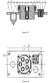
- Fig. 1 is a section view of a movable socket device in the embodiment of the invention
- Fig. 2 is a top view of the movable socket device in the embodiment of the invention.
- a socket module may include a first socket and a second socket.
- the first socket may be a five-hole socket and the second socket may be an eight-hole socket.
- the five-hole socket may specifically include a shell 5, an insulator 6, first contact pins 7, locating detents 8, an end cover 9 and a rubber gasket 10.
- the eight-hole socket may specifically include a shell 11, second contact pins 12, locating detents 13, a rubber gasket 14 and an insulator 15.
- first contact pins 7 and eight second contact pins there are five first contact pins 7 and eight second contact pins in total.
- the five first contact pins of the five-hole socket are arranged and spaced uniformly in the five-hole socket, and the distances between the five first contact pins and the periphery of the five-hole socket are equal to each other.
- a multi-strand flexible insulated wire with a diameter of 2.053mm and a cross section area of 3.3mm 2 (specification of AWG 12) is adopted as a connecting wire of the first contact pins.
- a multi-strand flexible insulated wire with a diameter of 1.291mm and a cross section area of 1.3mm 2 (specification of AWG 16) is adopted as a connecting wire of the second contact pins.
- first socket described in the embodiment of the invention may also be other types of sockets capable of being used to implement the invention, such as a three-hole socket
- second socket described in the embodiment of the invention may also be other types of sockets capable of being used to implement the invention, such as a five-hole socket.
- the movable socket device may further include a cover plate 2.
- the movable socket device further includes a tension spring 18.
- the tension spring 18 is fixed on a base plate 1 by a pin 17 and is riveted on a mounting plate 3 by a rivet 19.
- four corners of the movable mounting plate are riveted to four corners of the base plate via four tension springs, respectively.
- the mounting plate 3 and the tension springs 18 are located between the base plate 1 and the cover plate 2 and are invisible.
- the vertical distance between the mounting plate 3 and the base plate 1 is set to be, for example 30 millimeter (mm). It is easily conceivable for those skilled in the art that the tension spring component may be replaced by other retractable components, such as a spring or a reed.
- the movable socket device shown in Figs. 1 and 2 may further provided with a terminal board on the other side thereof opposite to the socket module.
- the terminal board may be connected with a standard battery frame to supply electric power to the battery of the electric vehicle in charging.
- the movable socket device may further include at least one guiding cylinder 4. Generally, two guiding cylinders 4 are provided to make a better connection between the plug device and the movable socket device.
- the movable socket device may further include a retainer ring 16, and sunk screws 20 and 21 for fixing the base plate 1. Also as shown in Fig. 2 , the space where the tension springs 18 are located is filled with high-grade lubricating grease 22, thus further ensuring movement of the movable socket device smoothly and conveniently.
- a section view of a plug device in the embodiment of the invention is shown.
- Fig. 4 is a top view of the plug device in the embodiment of the invention.
- the plug device may include a first plug and a second plug.
- the first plug may be a five-hole plug and the second plug may be an eight-hole plug.
- the five-hole plug may include a shell 3, an end cover 4, an insulator 5, locating detents 6, contacting rings 7 and jack sleeves 8.
- the eight-hole plug may include a shell 9, an insulator 10, locating detents 11, jack sleeves 12 and contact rings 13.
- the plug device is further provided with a guiding post 231. Generally, two guiding post 231 are provided.
- the plug device may further include a mounting plate 1. Also referring to Fig. 4 , the five-hole plug and the eight-hole plug are fixed on the mounting plate by sunk screws 15. Certainly, it is conceivable for those skilled in the art that the two plugs may be fixed on the mounting plate in other ways.
- the first plug described in the embodiment of the invention may also be other types of plugs capable of being used to implement the invention, such as a three-hole plug, and the second plug described in the embodiment of the invention may also be other types of plugs capable of being used to implement the invention, such as a five-hole plug.
- first jacks of the five-hole plug match with the first contact pins of the five-hole socket
- eight second jacks of the eight-hole plug match with the second contact pins of the eight-hole socket.
- the disengagement force between the first contact pin and the first jack may be checked by a corresponding standard contact pin, and when the roughness is Ra 0.8, the disengagement force should be ranged from 3 N to 6 N.
- the disengagement force between the second contact pin and the second jack may also be checked by a corresponding standard contact pin, and when the roughness is Ra 0.8, the disengagement force should be ranged from 0.3 N to 1.5 N.
- the interior of all of the first jacks and the second jacks may be coated with DJB-823 protective agent uniformly.
- the five jacks of the five-hole plug are matched with the first contact pins of the five-hole socket and the eight jacks of the eight-hole plug are matched with the second contact pins of the eight-hole socket.
- two guiding cylinders are generally provided for the movable socket device, and the guiding cylinders are matched with the guiding posts of the plug device.
- the guiding cylinders are fitted with the guiding posts of the plug device to position the charging connector, thereby achieving the movable connecting function.
- the moveable socket device shown in Fig. 2 in a practical application, among the five first contact pins in the figure, it is necessary that one is grounded; other two are used as cathodes of the five-hole socket and are connected to output cathodes of the five-hole plug; and the rest two are used as anodes of the five-hole socket and are connected to output anodes of the five-hole plug. It is to be noted that the five contact pins may be arranged in any orders and the fact that which contact pin is grounded or used as the anode and the cathode will not affect the implementation of the invention.
- the definitions of the pins corresponding to the five first contact pins of the five-hole socket can be made in any ways. In a practical application, among these five pins, it is necessary that one is grounded; other two are used as the cathodes of the five-hole socket and are connected to the output cathodes of the five-hole plug; and the rest two are used as the anodes of the five-hole socket and are connected to the output anodes of the five-hole plug.
- Table 1 Pin No. Pin connecting wire definition Dia. of the connecting wire remark 1 A fast charging socket, connected to the protective ground of a plug ( ) Two-colored, 25mm 2 Flexible wire 2 A cathode of the fast charging socket (-), connected to an output cathode of the plug (OUT-) Blue, 25mm 2 Flexible wire 3 A cathode of the fast charging socket (-), connected to an output cathode of the plug (OUT-) Blue, 25mm 2 4 An anode of the fast charging socket (+), connected to an output anode of the plug (OUT+) Brown, 25mm 2 Flexible wire 5 An anode of the fast charging socket (+), connected to an output anode of the plug (OUT+) Brown, 25mm 2
- the pins 1 to 5 in table 1 correspond to the five first contact pins which are indicated by numerals 1 to 5 in Fig. 2 , respectively.
- the pin 1 is used as a ground pin of the fast charging socket (five-hole socket) and is connected to the protective ground of the plug ( ).
- the pins 2 and 3 are used as the cathodes of the fast charging socket, and are connected to the output cathode of the plug (OUT-) when the battery is needed to be charged.
- the pins 4 and 5 are used as the anodes of the fast charging socket, and are connected to the output anodes of the plug (OUT+) when the battery is needed to be charged.
- the pin 1 is connected with a two-colored flexible wire of 25mm 2 in diameter; each of the pins 2 and 3 is connected with a blue flexible wire of 25mm 2 in diameter, and each of the pins 4 and 5 is connected with a brown flexible wire of 25mm 2 in diameter.
- table 1 is only a specific example, and other similar pin definitions can also be adopted to implement the invention.
- Table 4 Pin No. Pin connecting wire definition Dia. of the connecting wire remark 1 A fast charging socket -L-, connected to L-of a plug Black, 0.4mm 2 Background of the charging station 2
- a fast charging socket -L+ connected to L+ of the plug Red, 0.4mm 2 3
- a fast charging socket -CAN-L connected to CAN-L of shielded the plug twisted-pair wire 4
- a fast charging socket -CAN- shielding layer connected to CAN- shielding layer of the plug shielded twisted-pair layer 5
- a fast charging socket -CAN-H connected to CAN-H of the plug shielded twisted-pair wire 6
- a fast charging socket -CAN1-L with the other end being floating shielded twisted-pair wire Confirmation of permitting battery to be charged in background 7
- a fast charging socket -CANl-sheilding layer with the other end being floating shielded twisted-pair layer 8
- a fast charging socket -CAN1-L with the other end
- the pin 1 is used as the cathode of the power supply of the fast charging socket, and may be connected to the cathode of the power supply of the corresponding plug;
- the pin 2 is used as the anode of the power supply of the fast charging socket, and may be connected to the anode of the power supply of the corresponding plug;
- the pin 3 is used as the CAN-L (low level in the CAN bus) of the fast charging socket, and is connected to the CAN-L of the corresponding plug;
- the pin 4 is used as the CAN-shielding layer of the fast charging socket, and is connected to the CAN-shielding layer of the plug;
- the pin 5 is used as the CAN-H (high level in the CAN bus) of the fast charging socket, and is connected to the CAN-H of the plug.
- the pin 6 is used as the CAN1-L of the fast charging socket, with the other end being floating and not being connected with any terminal of the plug.
- the pin 7 is used as the CAN1-shielding layer of the fast charging socket, with the other end being floating and not being connected with any terminal of the plug.
- the pin 8 is used as the CAN1-H of the fast charging socket, with the other end being floating and not being connected with any terminal of the plug.
- the standard battery of the electric vehicle can be charged in a fast self-adaptive and effective way, thereby ensuring the normal operation of the electric vehicle.
- each of the five first jacks of the plug device shown in Fig. 4 corresponds to the definition of the five-hole socket.
- the five-hole plug shown in Fig. 4 it is necessary that one jack is grounded; two contact pins are used as the cathodes of the five-hole socket and are connected to the output cathodes of the five-hole plug; and the two rest contact pins are used as the anodes of the five-hole socket and are connected to the output anodes of the five-hole plug.
- the five contact pins may be arranged in any orders and the fact that which jack is grounded or used as the cathode or the anode will not affect the implementation of the invention.
- the definitions of the pins corresponding to the five first jacks of the five-hole plug may be made in any way.
- Table 3 a specific example of the definition of the pins is shown in table 3, in which the parameters of each pin of the five-hole plug are shown in table 3 as follows.
- the pin 1 is grounded; the pins 2 and 3 are connected to the cathodes of the battery terminal respectively; and the pins 4 and 5 are connected to the anodes of the battery terminal respectively.
- the batteries described in the embodiments of the invention are the standard battery modules used in the electric vehicle.
- the connecting wires have a diameter of 25mm 2 and generally adopt flexible wires, in which the connecting wire connected to the pin 1 is two-colored, the connecting wires connected to the pins 2 and 3 are blue, and the connecting wires connected to the pins 4 and 5 are brown.
- the pin 1 is connected to the cathode of the power supply, and the pin 2 is connected to the anode of the power supply, which are respectively distinguished with black and red flexible wires of 0.4mm 2 in diameter.
- the pin 3 is connected to CAN-L, the pin 4 is connected to CAN-shielding layer, and the pin 5 is connected to CAN-H, in which a shielded twisted-pair wire is used as the connecting wire.
- the pin 6 is connected to CAN-L, the pin 7 is connected to CAN1-sheilding layer, and the pin 8 is connected to CAN1-H.
- the pins 1, 2 and 3 are connected to the battery managing module of the background system.
- the pins 6, 7 and 8 are used to achieve the function of the confirmation of permitting the battery to be charged, and are mainly used to match the received input battery signal with the battery parameters (such as model) pre-stored in the background when the battery is charged. Specifically, if matched, the current charging of the battery is permitted, and if not matched, the battery is not permitted to continue the charge.
Landscapes
- Engineering & Computer Science (AREA)
- Power Engineering (AREA)
- Transportation (AREA)
- Mechanical Engineering (AREA)
- Electric Propulsion And Braking For Vehicles (AREA)
- Charge And Discharge Circuits For Batteries Or The Like (AREA)
- Secondary Cells (AREA)
- Details Of Connecting Devices For Male And Female Coupling (AREA)
Claims (11)
- Beweglicher Ladeverbinder, umfassend eine bewegliche Buchsenvorrichtung und eine Steckervorrichtung, wobei die bewegliche Buchsenvorrichtung auf einer Grundplatte (1) bereitgestellt ist und ein Buchsenmodul und mindestens einen Führungszylinder (4) umfasst, wobei das Buchsenmodul und der mindestens eine Führungszylinder (4) ortsfest auf einer beweglichen Montageplatte (3) bereitgestellt sind und eine Spannfeder (18) zwischen der beweglichen Montageplatte (3) und der Grundlatte (1) bereitgestellt ist, wobei vier Ecken der beweglichen Montageplatte (3) über vier derartige Spannfedern (18) an vier Ecken der Grundplatte (1) genietet sind, und
wobei, wenn die Steckervorrichtung und die bewegliche Buchsenvorrichtung miteinander verbunden sind, die bewegliche Montageplatte (3) und die Spannfeder (18) miteinander zusammenwirken, so dass die bewegliche Buchsenvorrichtung in jede Richtung bewegt werden kann. - Beweglicher Ladeverbinder nach Anspruch 1, dadurch gekennzeichnet, dass die bewegliche Buchsenvorrichtung ferner eine Deckplatte (2) umfasst und die bewegliche Montageplatte (3) und die Spannfeder (18) sich zwischen der Grundplatte (1) und der Deckplatte (2) befinden und nicht sichtbar sind.
- Beweglicher Ladeverbinder nach Anspruch 1, dadurch gekennzeichnet, dass eine Führungssäule (2), die mit dem Führungszylinder (4) versehen ist, in der Steckervorrichtung bereitgestellt ist.
- Beweglicher Ladeverbinder nach Anspruch 3, dadurch gekennzeichnet, dass die Anzahl der Führungszylinder (4) der beweglichen Buchsenvorrichtung zwei beträgt und die Führungszylinder (4) mit den Führungssäulen (231) der Steckervorrichtung gepaart sind.
- Beweglicher Ladeverbinder nach Anspruch 4, dadurch gekennzeichnet, dass die Führungszylinder (4) dafür gestaltet sind, mit den Führungssäulen (231) der Steckervorrichtung montiert zu sein, wenn die Steckervorrichtung und die bewegliche Buchsenvorrichtung miteinander verbunden sind, um den Ladeverbinder zu positionieren.
- Beweglicher Ladeverbinder nach Anspruch 1, dadurch gekennzeichnet, dass das Buchsenmodul eine erste Buchse und eine zweite Buchse umfasst, die erste Buchse mit einem Ladegerät verbunden ist, um mit einem hohen Strom zu laden, und die zweite Buchse mit einem Verwaltungssystem verbunden ist, um eine Ladeverwaltung und eine Ladeerlaubnis für eine Batterie zu erhalten.
- Beweglicher Ladeverbinder nach Anspruch 6, dadurch gekennzeichnet, dass große Kontaktstifte (7) in der ersten Buchse bereitgestellt sind und kleine Kontaktstifte (12) in der zweiten Buchse bereitgestellt sind, die großen Kontaktstifte (7) in der ersten Buchse gleichmäßig angeordnet und beabstandet sind und die Abstände zwischen den großen Kontaktstiften (7) und dem Umfang der ersten Buchse zueinander gleich sind.
- Beweglicher Ladeverbinder nach Anspruch 7, dadurch gekennzeichnet, dass die Steckervorrichtung einen ersten Stecker und einen zweiten Stecker umfasst, erste Buchsenteile des ersten Steckers mit den großen Kontaktstiften (7) der ersten Buchse gepaart sind, zweite Buchsenteile des zweiten Steckers mit den kleinen Kontaktstiften (12) des zweiten Steckers gepaart sind.
- Beweglicher Ladeverbinder nach Anspruch 7, dadurch gekennzeichnet, dass die bewegliche Buchsenvorrichtung mit einer Anschlussplatte auf ihrer anderen Seite gegenüber dem Buchsenmodul versehen ist und die Anschlussplatte dafür gestaltet ist, mit einem standardmäßigen Batterierahmen verbunden zu werden.
- Beweglicher Ladeverbinder nach Anspruch 7, dadurch gekennzeichnet, dass ein mehradriger flexibler isolierter Draht mit einem Durchmesser von 2,053 mm und einer Querschnittsfläche von 3,3 mm2 (AWG 12) als Verbindungsdraht der großen Kontaktstifte (7) angewendet wird.
- Beweglicher Ladeverbinder nach Anspruch 7, dadurch gekennzeichnet, dass ein mehradriger flexibler isolierter Draht mit einem Durchmesser von 1,291 mm und einer Querschnittsfläche von 1,3 mm2 (AWG 16) als Verbindungsdraht der kleinen Kontaktstifte (12) angewendet wird.
Applications Claiming Priority (2)
| Application Number | Priority Date | Filing Date | Title |
|---|---|---|---|
| CN2010101934570A CN101847805B (zh) | 2010-06-04 | 2010-06-04 | 一种可移动的充电联接器 |
| PCT/CN2010/076330 WO2011150598A1 (zh) | 2010-06-04 | 2010-08-25 | 一种可移动的充电联接器 |
Publications (3)
| Publication Number | Publication Date |
|---|---|
| EP2555342A1 EP2555342A1 (de) | 2013-02-06 |
| EP2555342A4 EP2555342A4 (de) | 2013-10-09 |
| EP2555342B1 true EP2555342B1 (de) | 2018-07-04 |
Family
ID=42772312
Family Applications (1)
| Application Number | Title | Priority Date | Filing Date |
|---|---|---|---|
| EP10847630.0A Not-in-force EP2555342B1 (de) | 2010-06-04 | 2010-08-25 | Beweglicher ladestecker |
Country Status (3)
| Country | Link |
|---|---|
| EP (1) | EP2555342B1 (de) |
| CN (1) | CN101847805B (de) |
| WO (1) | WO2011150598A1 (de) |
Cited By (1)
| Publication number | Priority date | Publication date | Assignee | Title |
|---|---|---|---|---|
| DE202018105926U1 (de) | 2018-10-16 | 2018-11-02 | Odu Gmbh & Co. Kg | Schwimmender Verbinder |
Families Citing this family (13)
| Publication number | Priority date | Publication date | Assignee | Title |
|---|---|---|---|---|
| CN102074823A (zh) * | 2010-10-27 | 2011-05-25 | 国家电网公司 | 电动汽车与交流供电装置之间的电气接口设备 |
| CN102683936A (zh) * | 2011-03-16 | 2012-09-19 | 贵阳普天物流技术股份有限公司 | 电动车换电充电系统平面连接器结构及其连接方法 |
| CN102324657A (zh) * | 2011-05-26 | 2012-01-18 | 苏州智绿环保科技有限公司 | 连接插座及使用该连接插座的充电接头 |
| CN103457298B (zh) | 2012-05-28 | 2016-04-27 | 比亚迪股份有限公司 | 一种充电转接口装置及具有该装置的立体车库 |
| CN103682816A (zh) * | 2013-11-25 | 2014-03-26 | 泰兴市航联电连接器有限公司 | 一种主动导向定位分离的电连接器 |
| CN103928778B (zh) * | 2014-04-17 | 2016-01-27 | 桑永礼 | 一种应急保障通信的快速供电卡接装置 |
| CN105281160A (zh) * | 2015-11-18 | 2016-01-27 | 桑永礼 | 快速供电连接头 |
| CN105514693A (zh) * | 2016-01-27 | 2016-04-20 | 江苏风雷光电科技有限公司 | 一种用于连接充电电池与充电装置的连接器 |
| CN106560966A (zh) * | 2016-04-28 | 2017-04-12 | 中兴新能源汽车有限责任公司 | 自动插接充电装置、智能立体车库及充电方法 |
| CN109416543B (zh) | 2016-06-30 | 2022-11-08 | 创科(澳门离岸商业服务)有限公司 | 一种自主式割草机及其导航系统 |
| JP7129377B2 (ja) * | 2019-04-26 | 2022-09-01 | 株式会社ハイレックスコーポレーション | ロック装置 |
| IT202200017349A1 (it) * | 2022-08-17 | 2024-02-17 | Te Connectivity Italia Distribution Srl | Metodo e sistema per connessione ad accoppiamento cieco |
| IL305179A (en) * | 2022-08-17 | 2024-03-01 | Te Connectivity Italia Distribution Srl | Method and system for blind connection |
Citations (1)
| Publication number | Priority date | Publication date | Assignee | Title |
|---|---|---|---|---|
| US7294010B1 (en) * | 2007-03-12 | 2007-11-13 | General Electric Co. | Connecting assembly with main and secondary connectors |
Family Cites Families (10)
| Publication number | Priority date | Publication date | Assignee | Title |
|---|---|---|---|---|
| GB2124839B (en) * | 1982-04-23 | 1986-03-26 | Woden Electrical Products Limi | Improvements in or relating to a battery charger for rechargeable batteries |
| CN2141131Y (zh) * | 1992-07-23 | 1993-08-25 | 上海仪表接插件厂 | 接线式电连接器 |
| CN2178949Y (zh) * | 1993-04-02 | 1994-10-05 | 赵旭林 | 安全插座 |
| DE9412219U1 (de) * | 1994-07-29 | 1995-11-23 | Varta Batterie Ag, 30419 Hannover | Automatisches Kupplungssystem für Fahrzeugbatterien |
| DE202004000387U1 (de) * | 2004-01-12 | 2004-04-01 | Erich Jaeger Gmbh & Co. Kg | Steckverbindungseinrichtung |
| CN201018151Y (zh) * | 2007-01-25 | 2008-02-06 | 北京首科能源技术有限公司 | 一种用于但不限于电动汽车用的充电安全连接器 |
| CN201061005Y (zh) * | 2007-05-18 | 2008-05-14 | 李铁英 | 安全插座 |
| EP2169776A1 (de) * | 2008-09-29 | 2010-03-31 | Delphi Technologies, Inc. | Elektrische Steckverbindung |
| CN101847806B (zh) * | 2010-06-04 | 2013-01-09 | 杭州市电力局 | 一种能够使充电联接器移动的装置 |
| CN201838857U (zh) * | 2010-06-04 | 2011-05-18 | 杭州市电力局 | 一种可移动的充电联接器 |
-
2010
- 2010-06-04 CN CN2010101934570A patent/CN101847805B/zh not_active Expired - Fee Related
- 2010-08-25 EP EP10847630.0A patent/EP2555342B1/de not_active Not-in-force
- 2010-08-25 WO PCT/CN2010/076330 patent/WO2011150598A1/zh not_active Ceased
Patent Citations (1)
| Publication number | Priority date | Publication date | Assignee | Title |
|---|---|---|---|---|
| US7294010B1 (en) * | 2007-03-12 | 2007-11-13 | General Electric Co. | Connecting assembly with main and secondary connectors |
Cited By (2)
| Publication number | Priority date | Publication date | Assignee | Title |
|---|---|---|---|---|
| DE202018105926U1 (de) | 2018-10-16 | 2018-11-02 | Odu Gmbh & Co. Kg | Schwimmender Verbinder |
| US11031730B2 (en) | 2018-10-16 | 2021-06-08 | Odu Gmbh & Co. Kg | Floating connector |
Also Published As
| Publication number | Publication date |
|---|---|
| CN101847805B (zh) | 2012-06-20 |
| WO2011150598A1 (zh) | 2011-12-08 |
| CN101847805A (zh) | 2010-09-29 |
| EP2555342A1 (de) | 2013-02-06 |
| EP2555342A4 (de) | 2013-10-09 |
Similar Documents
| Publication | Publication Date | Title |
|---|---|---|
| EP2555342A1 (de) | Beweglicher ladestecker | |
| CN110289523B (zh) | 一种浮动导向的电连接器及其应用 | |
| CN103515765A (zh) | 电接受器组件 | |
| CN204597029U (zh) | 一种电动汽车的换电连接装置 | |
| CN107891772A (zh) | 一种用于自动引导车的自动充电装置 | |
| CN207416569U (zh) | 一种车载无线充电装置 | |
| EP4144572A1 (de) | Elektrischer steckverbinder für ein elektrofahrzeug mit strom- und signalanschlüssen | |
| CN101847806B (zh) | 一种能够使充电联接器移动的装置 | |
| CN201838857U (zh) | 一种可移动的充电联接器 | |
| CN105514693A (zh) | 一种用于连接充电电池与充电装置的连接器 | |
| CN208690644U (zh) | 一种便于快速更换电池的连接器座 | |
| CN205039367U (zh) | 用于电动车的连接器和电动车 | |
| CN106711695A (zh) | 车载活动连接器及其组装方法、浮动连接器 | |
| CN206098893U (zh) | 一种便于安装的高压屏蔽电连接器组件 | |
| CN101882734B (zh) | 一种电池充电连接器 | |
| CN212209811U (zh) | 一种充电连接器及底盘充电设备 | |
| CN106159601B (zh) | 一种电动汽车交流充电导向式插座 | |
| CN105140736A (zh) | 用于电动车的连接器和电动车 | |
| CN201838858U (zh) | 一种电池充电连接器 | |
| CN110783880B (zh) | 10kV旁路作业系统专用连接装置 | |
| CN201789179U (zh) | 一种能够使充电联接器移动的装置 | |
| CN210201089U (zh) | 一种连接器 | |
| CN110171300A (zh) | 用于电动机动车的电池和用于给电池充电的充电装置 | |
| CN119381852A (zh) | 高压连接器和机电设备 | |
| CN201708404U (zh) | 一种插头和插座 |
Legal Events
| Date | Code | Title | Description |
|---|---|---|---|
| PUAI | Public reference made under article 153(3) epc to a published international application that has entered the european phase |
Free format text: ORIGINAL CODE: 0009012 |
|
| 17P | Request for examination filed |
Effective date: 20110921 |
|
| AK | Designated contracting states |
Kind code of ref document: A1 Designated state(s): AL AT BE BG CH CY CZ DE DK EE ES FI FR GB GR HR HU IE IS IT LI LT LU LV MC MK MT NL NO PL PT RO SE SI SK SM TR |
|
| DAX | Request for extension of the european patent (deleted) | ||
| A4 | Supplementary search report drawn up and despatched |
Effective date: 20130910 |
|
| RIC1 | Information provided on ipc code assigned before grant |
Ipc: H01R 13/46 20060101ALI20130904BHEP Ipc: H01R 24/00 20110101AFI20130904BHEP Ipc: H01R 13/629 20060101ALI20130904BHEP Ipc: H01R 13/631 20060101ALI20130904BHEP Ipc: H01R 27/02 20060101ALI20130904BHEP |
|
| 17Q | First examination report despatched |
Effective date: 20140627 |
|
| GRAP | Despatch of communication of intention to grant a patent |
Free format text: ORIGINAL CODE: EPIDOSNIGR1 |
|
| INTG | Intention to grant announced |
Effective date: 20180223 |
|
| GRAS | Grant fee paid |
Free format text: ORIGINAL CODE: EPIDOSNIGR3 |
|
| GRAA | (expected) grant |
Free format text: ORIGINAL CODE: 0009210 |
|
| RIN1 | Information on inventor provided before grant (corrected) |
Inventor name: ZHANG, FAN Inventor name: QI, JIAJIN Inventor name: HE, CHUNLIN Inventor name: NIE, LIANG Inventor name: DENG, GUANGBIN Inventor name: LI, BO Inventor name: XU, YU Inventor name: ZHU, CHENGZHI Inventor name: ZHENG, ZHENGXIAN Inventor name: ZHANG, PENGFEI |
|
| AK | Designated contracting states |
Kind code of ref document: B1 Designated state(s): AL AT BE BG CH CY CZ DE DK EE ES FI FR GB GR HR HU IE IS IT LI LT LU LV MC MK MT NL NO PL PT RO SE SI SK SM TR |
|
| REG | Reference to a national code |
Ref country code: GB Ref legal event code: FG4D |
|
| REG | Reference to a national code |
Ref country code: CH Ref legal event code: EP |
|
| REG | Reference to a national code |
Ref country code: AT Ref legal event code: REF Ref document number: 1015521 Country of ref document: AT Kind code of ref document: T Effective date: 20180715 |
|
| REG | Reference to a national code |
Ref country code: IE Ref legal event code: FG4D Ref country code: FR Ref legal event code: PLFP Year of fee payment: 9 |
|
| REG | Reference to a national code |
Ref country code: DE Ref legal event code: R096 Ref document number: 602010051729 Country of ref document: DE |
|
| REG | Reference to a national code |
Ref country code: NL Ref legal event code: MP Effective date: 20180704 |
|
| REG | Reference to a national code |
Ref country code: LT Ref legal event code: MG4D |
|
| REG | Reference to a national code |
Ref country code: AT Ref legal event code: MK05 Ref document number: 1015521 Country of ref document: AT Kind code of ref document: T Effective date: 20180704 |
|
| PG25 | Lapsed in a contracting state [announced via postgrant information from national office to epo] |
Ref country code: NL Free format text: LAPSE BECAUSE OF FAILURE TO SUBMIT A TRANSLATION OF THE DESCRIPTION OR TO PAY THE FEE WITHIN THE PRESCRIBED TIME-LIMIT Effective date: 20180704 |
|
| PG25 | Lapsed in a contracting state [announced via postgrant information from national office to epo] |
Ref country code: CZ Free format text: LAPSE BECAUSE OF FAILURE TO SUBMIT A TRANSLATION OF THE DESCRIPTION OR TO PAY THE FEE WITHIN THE PRESCRIBED TIME-LIMIT Effective date: 20180704 Ref country code: BG Free format text: LAPSE BECAUSE OF FAILURE TO SUBMIT A TRANSLATION OF THE DESCRIPTION OR TO PAY THE FEE WITHIN THE PRESCRIBED TIME-LIMIT Effective date: 20181004 Ref country code: IS Free format text: LAPSE BECAUSE OF FAILURE TO SUBMIT A TRANSLATION OF THE DESCRIPTION OR TO PAY THE FEE WITHIN THE PRESCRIBED TIME-LIMIT Effective date: 20181104 Ref country code: PL Free format text: LAPSE BECAUSE OF FAILURE TO SUBMIT A TRANSLATION OF THE DESCRIPTION OR TO PAY THE FEE WITHIN THE PRESCRIBED TIME-LIMIT Effective date: 20180704 Ref country code: AT Free format text: LAPSE BECAUSE OF FAILURE TO SUBMIT A TRANSLATION OF THE DESCRIPTION OR TO PAY THE FEE WITHIN THE PRESCRIBED TIME-LIMIT Effective date: 20180704 Ref country code: NO Free format text: LAPSE BECAUSE OF FAILURE TO SUBMIT A TRANSLATION OF THE DESCRIPTION OR TO PAY THE FEE WITHIN THE PRESCRIBED TIME-LIMIT Effective date: 20181004 Ref country code: LT Free format text: LAPSE BECAUSE OF FAILURE TO SUBMIT A TRANSLATION OF THE DESCRIPTION OR TO PAY THE FEE WITHIN THE PRESCRIBED TIME-LIMIT Effective date: 20180704 Ref country code: GR Free format text: LAPSE BECAUSE OF FAILURE TO SUBMIT A TRANSLATION OF THE DESCRIPTION OR TO PAY THE FEE WITHIN THE PRESCRIBED TIME-LIMIT Effective date: 20181005 Ref country code: FI Free format text: LAPSE BECAUSE OF FAILURE TO SUBMIT A TRANSLATION OF THE DESCRIPTION OR TO PAY THE FEE WITHIN THE PRESCRIBED TIME-LIMIT Effective date: 20180704 Ref country code: SE Free format text: LAPSE BECAUSE OF FAILURE TO SUBMIT A TRANSLATION OF THE DESCRIPTION OR TO PAY THE FEE WITHIN THE PRESCRIBED TIME-LIMIT Effective date: 20180704 |
|
| PG25 | Lapsed in a contracting state [announced via postgrant information from national office to epo] |
Ref country code: LV Free format text: LAPSE BECAUSE OF FAILURE TO SUBMIT A TRANSLATION OF THE DESCRIPTION OR TO PAY THE FEE WITHIN THE PRESCRIBED TIME-LIMIT Effective date: 20180704 Ref country code: AL Free format text: LAPSE BECAUSE OF FAILURE TO SUBMIT A TRANSLATION OF THE DESCRIPTION OR TO PAY THE FEE WITHIN THE PRESCRIBED TIME-LIMIT Effective date: 20180704 Ref country code: ES Free format text: LAPSE BECAUSE OF FAILURE TO SUBMIT A TRANSLATION OF THE DESCRIPTION OR TO PAY THE FEE WITHIN THE PRESCRIBED TIME-LIMIT Effective date: 20180704 Ref country code: HR Free format text: LAPSE BECAUSE OF FAILURE TO SUBMIT A TRANSLATION OF THE DESCRIPTION OR TO PAY THE FEE WITHIN THE PRESCRIBED TIME-LIMIT Effective date: 20180704 |
|
| REG | Reference to a national code |
Ref country code: CH Ref legal event code: PL |
|
| REG | Reference to a national code |
Ref country code: DE Ref legal event code: R097 Ref document number: 602010051729 Country of ref document: DE |
|
| PG25 | Lapsed in a contracting state [announced via postgrant information from national office to epo] |
Ref country code: CH Free format text: LAPSE BECAUSE OF NON-PAYMENT OF DUE FEES Effective date: 20180831 Ref country code: MC Free format text: LAPSE BECAUSE OF FAILURE TO SUBMIT A TRANSLATION OF THE DESCRIPTION OR TO PAY THE FEE WITHIN THE PRESCRIBED TIME-LIMIT Effective date: 20180704 Ref country code: LI Free format text: LAPSE BECAUSE OF NON-PAYMENT OF DUE FEES Effective date: 20180831 Ref country code: IT Free format text: LAPSE BECAUSE OF FAILURE TO SUBMIT A TRANSLATION OF THE DESCRIPTION OR TO PAY THE FEE WITHIN THE PRESCRIBED TIME-LIMIT Effective date: 20180704 Ref country code: EE Free format text: LAPSE BECAUSE OF FAILURE TO SUBMIT A TRANSLATION OF THE DESCRIPTION OR TO PAY THE FEE WITHIN THE PRESCRIBED TIME-LIMIT Effective date: 20180704 Ref country code: RO Free format text: LAPSE BECAUSE OF FAILURE TO SUBMIT A TRANSLATION OF THE DESCRIPTION OR TO PAY THE FEE WITHIN THE PRESCRIBED TIME-LIMIT Effective date: 20180704 Ref country code: LU Free format text: LAPSE BECAUSE OF NON-PAYMENT OF DUE FEES Effective date: 20180825 |
|
| PLBE | No opposition filed within time limit |
Free format text: ORIGINAL CODE: 0009261 |
|
| REG | Reference to a national code |
Ref country code: BE Ref legal event code: MM Effective date: 20180831 |
|
| STAA | Information on the status of an ep patent application or granted ep patent |
Free format text: STATUS: NO OPPOSITION FILED WITHIN TIME LIMIT |
|
| PG25 | Lapsed in a contracting state [announced via postgrant information from national office to epo] |
Ref country code: SM Free format text: LAPSE BECAUSE OF FAILURE TO SUBMIT A TRANSLATION OF THE DESCRIPTION OR TO PAY THE FEE WITHIN THE PRESCRIBED TIME-LIMIT Effective date: 20180704 Ref country code: DK Free format text: LAPSE BECAUSE OF FAILURE TO SUBMIT A TRANSLATION OF THE DESCRIPTION OR TO PAY THE FEE WITHIN THE PRESCRIBED TIME-LIMIT Effective date: 20180704 Ref country code: SK Free format text: LAPSE BECAUSE OF FAILURE TO SUBMIT A TRANSLATION OF THE DESCRIPTION OR TO PAY THE FEE WITHIN THE PRESCRIBED TIME-LIMIT Effective date: 20180704 |
|
| 26N | No opposition filed |
Effective date: 20190405 |
|
| PG25 | Lapsed in a contracting state [announced via postgrant information from national office to epo] |
Ref country code: SI Free format text: LAPSE BECAUSE OF FAILURE TO SUBMIT A TRANSLATION OF THE DESCRIPTION OR TO PAY THE FEE WITHIN THE PRESCRIBED TIME-LIMIT Effective date: 20180704 Ref country code: BE Free format text: LAPSE BECAUSE OF NON-PAYMENT OF DUE FEES Effective date: 20180831 |
|
| PG25 | Lapsed in a contracting state [announced via postgrant information from national office to epo] |
Ref country code: MT Free format text: LAPSE BECAUSE OF NON-PAYMENT OF DUE FEES Effective date: 20180825 |
|
| PG25 | Lapsed in a contracting state [announced via postgrant information from national office to epo] |
Ref country code: TR Free format text: LAPSE BECAUSE OF FAILURE TO SUBMIT A TRANSLATION OF THE DESCRIPTION OR TO PAY THE FEE WITHIN THE PRESCRIBED TIME-LIMIT Effective date: 20180704 |
|
| PG25 | Lapsed in a contracting state [announced via postgrant information from national office to epo] |
Ref country code: HU Free format text: LAPSE BECAUSE OF FAILURE TO SUBMIT A TRANSLATION OF THE DESCRIPTION OR TO PAY THE FEE WITHIN THE PRESCRIBED TIME-LIMIT; INVALID AB INITIO Effective date: 20100825 Ref country code: PT Free format text: LAPSE BECAUSE OF FAILURE TO SUBMIT A TRANSLATION OF THE DESCRIPTION OR TO PAY THE FEE WITHIN THE PRESCRIBED TIME-LIMIT Effective date: 20180704 |
|
| PG25 | Lapsed in a contracting state [announced via postgrant information from national office to epo] |
Ref country code: CY Free format text: LAPSE BECAUSE OF FAILURE TO SUBMIT A TRANSLATION OF THE DESCRIPTION OR TO PAY THE FEE WITHIN THE PRESCRIBED TIME-LIMIT Effective date: 20180704 Ref country code: MK Free format text: LAPSE BECAUSE OF NON-PAYMENT OF DUE FEES Effective date: 20180704 Ref country code: IE Free format text: LAPSE BECAUSE OF NON-PAYMENT OF DUE FEES Effective date: 20180825 |
|
| PGFP | Annual fee paid to national office [announced via postgrant information from national office to epo] |
Ref country code: GB Payment date: 20230824 Year of fee payment: 14 |
|
| PGFP | Annual fee paid to national office [announced via postgrant information from national office to epo] |
Ref country code: FR Payment date: 20230828 Year of fee payment: 14 Ref country code: DE Payment date: 20230808 Year of fee payment: 14 |
|
| REG | Reference to a national code |
Ref country code: DE Ref legal event code: R119 Ref document number: 602010051729 Country of ref document: DE |
|
| GBPC | Gb: european patent ceased through non-payment of renewal fee |
Effective date: 20240825 |
|
| PG25 | Lapsed in a contracting state [announced via postgrant information from national office to epo] |
Ref country code: DE Free format text: LAPSE BECAUSE OF NON-PAYMENT OF DUE FEES Effective date: 20250301 |
|
| PG25 | Lapsed in a contracting state [announced via postgrant information from national office to epo] |
Ref country code: GB Free format text: LAPSE BECAUSE OF NON-PAYMENT OF DUE FEES Effective date: 20240825 |
|
| PG25 | Lapsed in a contracting state [announced via postgrant information from national office to epo] |
Ref country code: FR Free format text: LAPSE BECAUSE OF NON-PAYMENT OF DUE FEES Effective date: 20240831 |