EP2555289A1 - Metal foil for negative electrode collector - Google Patents
Metal foil for negative electrode collector Download PDFInfo
- Publication number
- EP2555289A1 EP2555289A1 EP11762479A EP11762479A EP2555289A1 EP 2555289 A1 EP2555289 A1 EP 2555289A1 EP 11762479 A EP11762479 A EP 11762479A EP 11762479 A EP11762479 A EP 11762479A EP 2555289 A1 EP2555289 A1 EP 2555289A1
- Authority
- EP
- European Patent Office
- Prior art keywords
- metal foil
- holes
- negative electrode
- foil
- electrode collector
- Prior art date
- Legal status (The legal status is an assumption and is not a legal conclusion. Google has not performed a legal analysis and makes no representation as to the accuracy of the status listed.)
- Withdrawn
Links
Images


Classifications
-
- H—ELECTRICITY
- H01—ELECTRIC ELEMENTS
- H01M—PROCESSES OR MEANS, e.g. BATTERIES, FOR THE DIRECT CONVERSION OF CHEMICAL ENERGY INTO ELECTRICAL ENERGY
- H01M4/00—Electrodes
- H01M4/02—Electrodes composed of, or comprising, active material
- H01M4/64—Carriers or collectors
- H01M4/70—Carriers or collectors characterised by shape or form
-
- C—CHEMISTRY; METALLURGY
- C23—COATING METALLIC MATERIAL; COATING MATERIAL WITH METALLIC MATERIAL; CHEMICAL SURFACE TREATMENT; DIFFUSION TREATMENT OF METALLIC MATERIAL; COATING BY VACUUM EVAPORATION, BY SPUTTERING, BY ION IMPLANTATION OR BY CHEMICAL VAPOUR DEPOSITION, IN GENERAL; INHIBITING CORROSION OF METALLIC MATERIAL OR INCRUSTATION IN GENERAL
- C23F—NON-MECHANICAL REMOVAL OF METALLIC MATERIAL FROM SURFACE; INHIBITING CORROSION OF METALLIC MATERIAL OR INCRUSTATION IN GENERAL; MULTI-STEP PROCESSES FOR SURFACE TREATMENT OF METALLIC MATERIAL INVOLVING AT LEAST ONE PROCESS PROVIDED FOR IN CLASS C23 AND AT LEAST ONE PROCESS COVERED BY SUBCLASS C21D OR C22F OR CLASS C25
- C23F1/00—Etching metallic material by chemical means
- C23F1/02—Local etching
-
- C—CHEMISTRY; METALLURGY
- C23—COATING METALLIC MATERIAL; COATING MATERIAL WITH METALLIC MATERIAL; CHEMICAL SURFACE TREATMENT; DIFFUSION TREATMENT OF METALLIC MATERIAL; COATING BY VACUUM EVAPORATION, BY SPUTTERING, BY ION IMPLANTATION OR BY CHEMICAL VAPOUR DEPOSITION, IN GENERAL; INHIBITING CORROSION OF METALLIC MATERIAL OR INCRUSTATION IN GENERAL
- C23F—NON-MECHANICAL REMOVAL OF METALLIC MATERIAL FROM SURFACE; INHIBITING CORROSION OF METALLIC MATERIAL OR INCRUSTATION IN GENERAL; MULTI-STEP PROCESSES FOR SURFACE TREATMENT OF METALLIC MATERIAL INVOLVING AT LEAST ONE PROCESS PROVIDED FOR IN CLASS C23 AND AT LEAST ONE PROCESS COVERED BY SUBCLASS C21D OR C22F OR CLASS C25
- C23F1/00—Etching metallic material by chemical means
- C23F1/10—Etching compositions
- C23F1/14—Aqueous compositions
-
- G—PHYSICS
- G03—PHOTOGRAPHY; CINEMATOGRAPHY; ANALOGOUS TECHNIQUES USING WAVES OTHER THAN OPTICAL WAVES; ELECTROGRAPHY; HOLOGRAPHY
- G03F—PHOTOMECHANICAL PRODUCTION OF TEXTURED OR PATTERNED SURFACES, e.g. FOR PRINTING, FOR PROCESSING OF SEMICONDUCTOR DEVICES; MATERIALS THEREFOR; ORIGINALS THEREFOR; APPARATUS SPECIALLY ADAPTED THEREFOR
- G03F7/00—Photomechanical, e.g. photolithographic, production of textured or patterned surfaces, e.g. printing surfaces; Materials therefor, e.g. comprising photoresists; Apparatus specially adapted therefor
- G03F7/0015—Production of aperture devices, microporous systems or stamps
-
- G—PHYSICS
- G03—PHOTOGRAPHY; CINEMATOGRAPHY; ANALOGOUS TECHNIQUES USING WAVES OTHER THAN OPTICAL WAVES; ELECTROGRAPHY; HOLOGRAPHY
- G03F—PHOTOMECHANICAL PRODUCTION OF TEXTURED OR PATTERNED SURFACES, e.g. FOR PRINTING, FOR PROCESSING OF SEMICONDUCTOR DEVICES; MATERIALS THEREFOR; ORIGINALS THEREFOR; APPARATUS SPECIALLY ADAPTED THEREFOR
- G03F7/00—Photomechanical, e.g. photolithographic, production of textured or patterned surfaces, e.g. printing surfaces; Materials therefor, e.g. comprising photoresists; Apparatus specially adapted therefor
- G03F7/20—Exposure; Apparatus therefor
- G03F7/2022—Multi-step exposure, e.g. hybrid; backside exposure; blanket exposure, e.g. for image reversal; edge exposure, e.g. for edge bead removal; corrective exposure
- G03F7/2032—Simultaneous exposure of the front side and the backside
-
- H—ELECTRICITY
- H01—ELECTRIC ELEMENTS
- H01G—CAPACITORS; CAPACITORS, RECTIFIERS, DETECTORS, SWITCHING DEVICES, LIGHT-SENSITIVE OR TEMPERATURE-SENSITIVE DEVICES OF THE ELECTROLYTIC TYPE
- H01G11/00—Hybrid capacitors, i.e. capacitors having different positive and negative electrodes; Electric double-layer [EDL] capacitors; Processes for the manufacture thereof or of parts thereof
- H01G11/66—Current collectors
- H01G11/68—Current collectors characterised by their material
-
- H—ELECTRICITY
- H01—ELECTRIC ELEMENTS
- H01G—CAPACITORS; CAPACITORS, RECTIFIERS, DETECTORS, SWITCHING DEVICES, LIGHT-SENSITIVE OR TEMPERATURE-SENSITIVE DEVICES OF THE ELECTROLYTIC TYPE
- H01G11/00—Hybrid capacitors, i.e. capacitors having different positive and negative electrodes; Electric double-layer [EDL] capacitors; Processes for the manufacture thereof or of parts thereof
- H01G11/66—Current collectors
- H01G11/70—Current collectors characterised by their structure
-
- H—ELECTRICITY
- H01—ELECTRIC ELEMENTS
- H01G—CAPACITORS; CAPACITORS, RECTIFIERS, DETECTORS, SWITCHING DEVICES, LIGHT-SENSITIVE OR TEMPERATURE-SENSITIVE DEVICES OF THE ELECTROLYTIC TYPE
- H01G11/00—Hybrid capacitors, i.e. capacitors having different positive and negative electrodes; Electric double-layer [EDL] capacitors; Processes for the manufacture thereof or of parts thereof
- H01G11/74—Terminals, e.g. extensions of current collectors
-
- H—ELECTRICITY
- H01—ELECTRIC ELEMENTS
- H01M—PROCESSES OR MEANS, e.g. BATTERIES, FOR THE DIRECT CONVERSION OF CHEMICAL ENERGY INTO ELECTRICAL ENERGY
- H01M4/00—Electrodes
- H01M4/02—Electrodes composed of, or comprising, active material
- H01M4/64—Carriers or collectors
- H01M4/66—Selection of materials
- H01M4/661—Metal or alloys, e.g. alloy coatings
-
- H—ELECTRICITY
- H01—ELECTRIC ELEMENTS
- H01M—PROCESSES OR MEANS, e.g. BATTERIES, FOR THE DIRECT CONVERSION OF CHEMICAL ENERGY INTO ELECTRICAL ENERGY
- H01M4/00—Electrodes
- H01M4/02—Electrodes composed of, or comprising, active material
- H01M4/64—Carriers or collectors
- H01M4/70—Carriers or collectors characterised by shape or form
- H01M4/72—Grids
- H01M4/74—Meshes or woven material; Expanded metal
- H01M4/742—Meshes or woven material; Expanded metal perforated material
-
- H—ELECTRICITY
- H01—ELECTRIC ELEMENTS
- H01G—CAPACITORS; CAPACITORS, RECTIFIERS, DETECTORS, SWITCHING DEVICES, LIGHT-SENSITIVE OR TEMPERATURE-SENSITIVE DEVICES OF THE ELECTROLYTIC TYPE
- H01G11/00—Hybrid capacitors, i.e. capacitors having different positive and negative electrodes; Electric double-layer [EDL] capacitors; Processes for the manufacture thereof or of parts thereof
- H01G11/04—Hybrid capacitors
- H01G11/06—Hybrid capacitors with one of the electrodes allowing ions to be reversibly doped thereinto, e.g. lithium ion capacitors [LIC]
-
- Y—GENERAL TAGGING OF NEW TECHNOLOGICAL DEVELOPMENTS; GENERAL TAGGING OF CROSS-SECTIONAL TECHNOLOGIES SPANNING OVER SEVERAL SECTIONS OF THE IPC; TECHNICAL SUBJECTS COVERED BY FORMER USPC CROSS-REFERENCE ART COLLECTIONS [XRACs] AND DIGESTS
- Y02—TECHNOLOGIES OR APPLICATIONS FOR MITIGATION OR ADAPTATION AGAINST CLIMATE CHANGE
- Y02E—REDUCTION OF GREENHOUSE GAS [GHG] EMISSIONS, RELATED TO ENERGY GENERATION, TRANSMISSION OR DISTRIBUTION
- Y02E60/00—Enabling technologies; Technologies with a potential or indirect contribution to GHG emissions mitigation
- Y02E60/10—Energy storage using batteries
-
- Y—GENERAL TAGGING OF NEW TECHNOLOGICAL DEVELOPMENTS; GENERAL TAGGING OF CROSS-SECTIONAL TECHNOLOGIES SPANNING OVER SEVERAL SECTIONS OF THE IPC; TECHNICAL SUBJECTS COVERED BY FORMER USPC CROSS-REFERENCE ART COLLECTIONS [XRACs] AND DIGESTS
- Y02—TECHNOLOGIES OR APPLICATIONS FOR MITIGATION OR ADAPTATION AGAINST CLIMATE CHANGE
- Y02E—REDUCTION OF GREENHOUSE GAS [GHG] EMISSIONS, RELATED TO ENERGY GENERATION, TRANSMISSION OR DISTRIBUTION
- Y02E60/00—Enabling technologies; Technologies with a potential or indirect contribution to GHG emissions mitigation
- Y02E60/13—Energy storage using capacitors
Definitions
- the present invention relates to a novel metal foil for a negative electrode collector. More specifically, the present invention relates to a metal foil for a negative electrode collector that is used as a collector in a lithium ion battery, a lithium ion capacitor, an electrical double layer capacitor and the like.
- positive electrode collectors are made from aluminum, stainless steel and the like
- negative electrode collectors are made from stainless steel, copper, nickel and the like.
- Punching, mesh processing, expansion processing, net processing and the like are known as methods for preparing collectors having through holes, but through holes formed using these methods are generally 0.1 to 0.3 mm in size (see Japanese Patent Application Publication No. 2004-103314 ).
- simply providing through holes reduces the strength of a collector, and through holes having relatively large diameters, such as those mentioned above, exacerbate the problem of reduced strength.
- a lithium ion capacitor which is provided with a positive electrode comprising a substance able to reversibly support lithium ions and/or anions and a negative electrode comprising a substance able to reversibly support lithium ions and which is provided with an aprotic organic solvent electrolyte solution of lithium salt as an electrolyte, wherein the capacitor has a collector comprising a metal foil in which (1) the negative electrode and/or positive electrode are doped with lithium ions by electrochemically connecting the negative electrode and/or the positive electrode with a lithium ion supply source, (2) the potential of the positive electrode is 2.0 V or lower after short circuiting the positive electrode and the negative electrode, and (3) the aforementioned positive electrode and/or negative electrode have a multiplicity of through holes between the front and rear surfaces and the average inscribed circle diameter of these through holes is 100 ⁇ m or lower, is known (see WO 2008/078777 ).
- a collector comprising an aluminum etched foil which has a thickness of 20 to 45 ⁇ m, an apparent density of 2.00 to 2.54 g/cm 3 and an air permeability of 20 to 120 s and which has a multiplicity of through holes between the front and rear surfaces, wherein 80% or more of the aforementioned through holes have hole diameters of 1 to 30 ⁇ m, is known as a positive electrode collector used in a lithium ion capacitor such as that mentioned above (see Japanese Patent Application Publication No. 2009-62595 ).
- electrodes that use conventional negative electrode collectors have relatively high resistance (internal resistance) for electrodes, which can lead to concerns regarding adverse effects on charging and discharging characteristics when used in batteries and the like.
- causes of increased electrode resistance include the state of distribution of through holes in a collector and adhesion between a collector and an active substance, and it is therefore necessary to improve these characteristics.
- the main objective of the present invention is to provide a metal foil for a negative electrode collector, by which it is possible to achieve a lower resistance value.
- the present invention relates to the following metal foil for a negative electrode collector.
- the present invention by controlling the distribution of through holes within a specified range, it is possible to achieve a lower resistance value than conventional collectors when using the collector in an electrode.
- This type of metal foil for a negative electrode collector can be preferably used as a collector for a lithium ion battery, a lithium ion capacitor, and electrical double layer capacitor and the like.
- the metal foil for a negative electrode collector of the present invention is useful as a negative electrode collector of a lithium ion capacitor or a lithium ion secondary battery which comprises 1) a positive electrode comprising a substance able to reversibly support lithium ions and/or anions, 2) a negative electrode comprising a substance able to reversibly support lithium ions, and 3) an electrolyte solution that contains lithium ions, and in which the positive electrode and/or negative electrode are doped with lithium ions.
- the metal foil for a negative electrode collector of the present invention is characterized by having a plurality of through holes that reach the foil rear surface from the foil front surface and having a region having a through hole density of 1000 holes/cm 2 or more (a through hole region) . That is, the metal foil of the present invention is characterized by having a plurality of through holes that reach the foil rear surface from the foil front surface and having a through hole density of 1,000 holes/cm 2 or more in a 1 cm 2 region at an arbitrary location.
- the metal used in the metal foil of the present invention can be a material (a metal foil) according to those used in conventional negative electrode collectors for batteries.
- a metal foil a material according to those used in conventional negative electrode collectors for batteries.
- copper it is possible to use a rolled copper foil, an electrolytic copper foil and the like.
- the thickness of the metal foil is not limited, but is generally within the range 3 to 100 ⁇ m, and can be set as appropriate according to, for example, the type of metal foil used. For example, when using a copper foil as the metal foil, a thickness of 8 to 25 ⁇ m is more preferred.
- the through holes are holes 13 that penetrate from the front surface 11 to the rear surface 12 of the metal foil 10, as shown in FIG. 2 .
- the through hole density is 1000 holes/cm 2 or higher, preferably 1500 to 30000 holes/cm 2 , and more preferably 2000 to 20000 holes/cm 2 .
- the size of the through holes is also not limited, but the average internal diameter of the through holes is preferably 100 ⁇ m or lower, and especially 90 ⁇ m or lower. By setting the average internal diameter to fall within the above-mentioned range, it is possible to more evenly control the thickness of a coating film when an active substance (slurry) is coated on the metal foil of the present invention.
- the average internal diameter of the through holes means the diameter calculated from the average area of the through holes, on the assumption that the through holes are circles.
- the aperture ratio in the metal foil of the present invention is generally 40% or lower, and preferably 30% or lower.
- the aperture ratio was set to a higher value in order for ions to pass through the collector more easily, but a larger aperture ratio resulted not only in a reduction in foil strength, but also made it difficult to evenly coat an active substance on the foil, resulted in the active substance inside the through holes shrinking during drying after coating, and led to the active substance peeling or cracking more readily.
- the aperture ratio is the ratio of the total area occupied by openings of through holes relative to the overall area of the region containing through holes on the surface of the metal foil.
- the foil thickness and aperture ratio of the metal foil of the present invention to satisfy the relationship:
- the metal foil of the present invention may contain a region other than a through hole region. That is, the metal foil of the present invention may contain a region having a through a hole density of less than 1000 holes/cm 2 (preferably 500 holes/cm 2 or lower, more preferably 100 holes/cm 2 or lower, and most preferably 0 holes/cm 2 ) (hereinafter referred to as a "support region") . If the metal foil of the present invention contains a support region, the support region acts to support the through hole region, and it is therefore possible to effectively maintain the strength of the overall metal foil.
- the area and pattern of the support region can be set as appropriate according to, for example, the thickness, material and intended use of the metal foil of the present invention.
- FIG. 3 it is possible to obtain 1) a pattern whereby a support region is provided around the periphery of a rectangular through hole region, 2] a pattern whereby a support region is provided at one edge of a rectangular through hole region, 3) a pattern whereby support regions are provided at both edges of a rectangular through hole region, or 4) a pattern whereby through hole regions and support regions are provided alternately in a striped pattern.
- the areal ratio of the through hole region(s) and support region (s) is not limited, and can be set as appropriate according to the desired battery characteristics and the like.
- the total area of through hole regions to be 100 mm 2 or more in the present invention. 2.
- the metal foil of the present invention can be produced using a publicly known method except that the through hole density and the like is controlled within a prescribed range. For example, it is possible to obtain the metal foil of the present invention by etching a metal foil having a prescribed thickness.
- etching it is possible to preferably use a method that includes, for example, 1) a step of forming a photoresist film on the surface of a metal foil (a photoresist film formation step), 2) a step of exposing the photoresist film to UV light via a photomask (an exposure step), 3) a step of removing a prescribed pattern part from the photoresist film by developing (a developing step), 4) a step of forming through holes in the metal foil by etching (an etching step), and 5) a step of removing the remaining photoresist film (a peeling step).
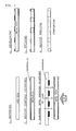
- FIG. 1 is a schematic cross sectional view showing the order of steps for forming through holes in a metal foil for a collector according to one embodiment of the production method of the present invention.
- a metal foil in which through holes are to be formed is prepared as shown in "1, Material" in FIG. 1 .
- the metal foil is not particularly limited as long as etching with an acid or alkali is possible and the metal foil can be used as a collector for a secondary battery.
- This type of metal foil can generally be an aluminum foil, an aluminum alloy foil, a copper foil, a stainless steel foil, a nickel foil and the like.
- the thickness of the metal foil is not limited, but is generally 3 to 100 ⁇ m, and preferably 8 to 50 ⁇ m. If the thickness of the metal foil is less than 3 ⁇ m, the strength of the metal foil is extremely low and the metal foil easily breaks during the collector production process. However, if the thickness of the metal foil exceeds 100 ⁇ m, the weight of the ultimately obtained secondary battery increases.
- the components of the aluminum or aluminum alloy can be selected as appropriate from among pure aluminum (JIS 1000 type), an aluminum-manganese (Al-Mn)-based alloy (JIS 3000 type), an aluminum-magnesium (Al-Mg)-based alloy (JIS 5000 type), and aluminum-iron (A1-Fe)-based alloy (JIS 8000 type) and the like according to the type of electrolyte in the secondary battery.
- a photoresist film is formed on the surface of the metal foil in the photoresist film formation step shown in "2, Resist coating" in FIG. 1 .
- the photoresist film formation can be carried out using known methods, such as 1) a method of printing or coating a solution or dispersion of a synthetic resin on the metal foil, 2) a method of dipping the metal foil in a solution or dispersion of a synthetic resin, or 3) a method of laminating a pre-formed synthetic resin on the metal foil. If a printing method is used, it is possible to use, for example, gravure printing, transfer printing or screen printing. In addition, in cases where a solution or dispersion of a synthetic resin is used, as mentioned above, drying can generally be carried out at a temperature of 30 to 150°C for a period of between 10 seconds and 10 minutes.
- the synthetic resin can be one known as a photoresist film.
- a photoresist film For example, it is possible to use an acrylic resin, polyethylene terephthalate, polypropylene, polyethylene and the like.
- an acrylic resin is preferably used. More specifically, it is preferable to use a negative resist formed from an acrylic resin.
- the thickness of the photoresist film formed on the metal foil can be set as appropriate according to the type of synthetic resin used, but can generally be 1 to 50 ⁇ m.
- the photoresist film may be formed on one or both sides of the metal foil.
- the photoresist film is exposed to UV light via a photomask in the exposure step shown in "3, Exposure" in FIG. 1 .
- the period of exposure to UV light (the irradiation time) and the intensity of the UV light canbe set in accordance with conventional methods.
- a photomask may be used on one or both surfaces of the metal foil, but in view of stabilizing the pitch of the through holes and simplifying the equipment, it is preferable to use a photomask on one surface of the metal foil. That is, it is preferable for a photoresist film to be exposed to UV light via a photomask on one surface of the metal foil, and for the entire surface of the photoresist film on the other surface of the metal foil to be exposed to UV light. By doing so, the entire surface of the rear surface is exposed to UV light without a photomask, thereby enabling the entire photoresist film on the rear surface to be cured.
- the exposure method and photomasking method can be carried out by forming a desired pattern in accordance with conditions set with a publicly known exposure device (a photo-plotter and the like). As shown in "3, Exposure" in FIG. 1 , a photomask can be disposed at fixed intervals so that prescribed through holes can be formed, and irradiation can then be carried out for a certain period of time with UV light (ultraviolet radiation) having a prescribed intensity.
- the intensity of the UV light can also be set as appropriate according to the thickness of the photoresist film. For example, if the thickness of the photoresist film is approximately 5 ⁇ m, the intensity of the UV light can be adjusted to approximately 50 mj/cm 2 .
- Developing in FIG. 1 , a prescribed pattern part of the photoresist film is removed by developing.
- the developing method can be similar to publicly known methods. Removal of the photoresist film can also be carried out in accordance with known developing methods. For example, by dipping for approximately 1 minute in a 1% aqueous solution of Na 2 CO 3 (sodium carbonate) at a liquid temperature of 30°C, it is possible to remove the photoresist film.
- etching liquid can be, for example, a single solution (or aqueous solution) of sulfuric acid, phosphoric acid, chromic acid, nitric acid, hydrofluoric acid, acetic acid, caustic soda, ferric chloride, cupric chloride, perchloric acid and the like, or a mixed solution of these.
- a solvent such as water.
- the etching conditions can be set according to publicly known etching methods.
- the liquid temperature can be approximately 25 to 60°C
- the treatment time can be approximately 10 seconds to 5 minutes.
- the remaining photoresist film is removed.
- the photoresist film canbe removed using, for example, a weakly alkaline aqueous solution.
- the weakly alkaline aqueous solution can be, for example, an aqueous solution of sodium hydroxide.
- a treatment such as drying the metal foil may be carried out if necessary in the present invention.
- the metal foil of the present invention which is obtained as described above, can be formed into a product by winding into a coil if necessary. Thereafter, the metal foil of the present invention may be cut to an appropriate size if necessary and supplied to a step in which an active substance is coated on the metal foil.
- the surface was observed under a microscope (manufactured by Keyence Corporation), and the through hole density was measured.
- Photographs of 10 fields of view were taken at random using the same method as that used in (2) above, image analysis was carried out in order to measure the number of through holes and the total through hole area, and the internal diameters of the through holes were calculated on the assumption that all the through holes were identical circles.
- the image analysis device was a "PCA11" multi-purpose high-speed image analysis device (manufactured by System Science Co., Ltd.).
- a coiled electrolytic copper foil having a thickness of 10 ⁇ m, a width of 300 mm and a length of 250 m was dip coated with a solution of an acrylic resin negative photoresist so as to coat both surfaces of the copper foil with the acrylic resin at a thickness of 5 ⁇ m, and the coated copper foil was then dried at 80°C.
- One surface of the metal foil was irradiated with UV light at an intensity of 100 mj/cm 2 via a photomask on which the pattern shown in FIG. 4 was drawn by means of a photo-plotter, and the whole of the other surface of the metal foil was irradiated with the above-mentioned UV light without using a photomask.
- the metal foil was dipped in a solution of sodium carbonate in order to dissolve and remove the photoresist on the photomask section.
- the metal foil was etched by dipping the obtained material in cupric chloride at a liquid temperature of 50°C. The dipping time was 30 seconds. Following the etching, the metal foil was dipped in a solution of sodium hydroxide (NaOH) so as to peel off the photoresist layer. Corrosion prevention treatment, washing and drying were then carried out. A metal foil for a negative electrode collector was obtained in this way.
- a metal foil was obtained in the same way as Example 1, except that the pattern shown in FIG. 4 (b) was used and the through hole density and the average internal diameter of the through holes were as shown in Table 1.
- Example 1 The through hole density and the like of the metal foils for negative electrode collectors obtained in Example 1 and Comparative Example 1 were investigated. These results are shown in Table 1.
- Table 1 Through hole density (holes/cm 2 ) Average internal diameter of through holes ( ⁇ m) Foil thickness/aperture ratio ( ⁇ m/%) Aperture ratio (%) Example 5000 80 ⁇ m ⁇ 0.40 25 Comparative Example 200 500 ⁇ m ⁇ 0.25 40
- negative electrodes were prepared by cutting out the obtainedmetal foils, which have lengths of approximately 50 cm, at a part approximately 5 m and a part approximately 900 m in the length direction after the start of the etching, than coating with a slurry containing an active substance composed of carbon particles, and then cutting to sizes of 10 cm ⁇ 20 cm.
- the coating characteristics in the above-mentioned slurry-coating step were confirmed.
- a battery such as that shown in FIG. 5 was assembled according to the disclosures in WO 2008/078777 , and the capacity (mAh) and internal resistance (m ⁇ ) of this battery were investigated. These results are shown in Table 2.
- the electrolyte was an organic LIC electrolyte and the electrode structure was a laminated cell type.
- the above-mentioned cell was subjected to a charging and discharging test and the capacity was calculated from the discharging time.
- the discharging was carried out at a current of 53 mA/cm 2 , and the capacity was calculated by multiplying the current by the discharging time required for the voltage to reach 2.2 V from 3.8 V.
- the internal resistance was calculated using Ohm's Law from the value of the discharging current and the value of the voltage drop that occurred when switching between charging and discharging (the IR drop).
- An electrode coating liquid containing a negative electrode active substance was coated (to a thickness of 20 ⁇ m on each surface) on both surfaces of a copper collector having through holes using a die coater.
- a leak check (10 m) and a check for the occurrence of surface patterns (the occurrence of differences in coating thickness) were carried out as checks following coating.
- a case in which a leak or a surface pattern was confirmed visually was evaluated as " ⁇ ” and a case in which these were not confirmed was evaluated as " ⁇ ".
Landscapes
- Chemical & Material Sciences (AREA)
- Engineering & Computer Science (AREA)
- Chemical Kinetics & Catalysis (AREA)
- General Chemical & Material Sciences (AREA)
- Power Engineering (AREA)
- Materials Engineering (AREA)
- Electrochemistry (AREA)
- Microelectronics & Electronic Packaging (AREA)
- Physics & Mathematics (AREA)
- General Physics & Mathematics (AREA)
- Organic Chemistry (AREA)
- Metallurgy (AREA)
- Mechanical Engineering (AREA)
- Cell Electrode Carriers And Collectors (AREA)
- Electric Double-Layer Capacitors Or The Like (AREA)
- ing And Chemical Polishing (AREA)
Abstract
Description
- The present invention relates to a novel metal foil for a negative electrode collector. More specifically, the present invention relates to a metal foil for a negative electrode collector that is used as a collector in a lithium ion battery, a lithium ion capacitor, an electrical double layer capacitor and the like.
- In lithium ion batteries, lithium ion capacitors and electrical double layer capacitors and the like, positive electrode collectors are made from aluminum, stainless steel and the like, and negative electrode collectors are made from stainless steel, copper, nickel and the like.
- Higher voltages are required in order to improve the energy density in these lithium ion batteries, lithium ion capacitors, electrical double layer capacitors and the like. In order to increase the energy density, it is preferable to use a pre-doping technique and reduce the negative electrode potential. In addition, in order to carry out pre-doping with good efficiency, it is necessary to provide through holes in a collector. That is, it is possible to support lithium ions in a negative electrode active substance by providing through holes in a collector so as to enable reversible transfer of the lithium ions.
- Punching, mesh processing, expansion processing, net processing and the like are known as methods for preparing collectors having through holes, but through holes formed using these methods are generally 0.1 to 0.3 mm in size (see Japanese Patent Application Publication No.
2004-103314 - In contrast, proposals have been made for electrodes using collectors having relatively fine through holes. For example, a lithium ion capacitor which is provided with a positive electrode comprising a substance able to reversibly support lithium ions and/or anions and a negative electrode comprising a substance able to reversibly support lithium ions and which is provided with an aprotic organic solvent electrolyte solution of lithium salt as an electrolyte, wherein the capacitor has a collector comprising a metal foil in which (1) the negative electrode and/or positive electrode are doped with lithium ions by electrochemically connecting the negative electrode and/or the positive electrode with a lithium ion supply source, (2) the potential of the positive electrode is 2.0 V or lower after short circuiting the positive electrode and the negative electrode, and (3) the aforementioned positive electrode and/or negative electrode have a multiplicity of through holes between the front and rear surfaces and the average inscribed circle diameter of these through holes is 100 µm or lower, is known (see
WO 2008/078777 ). - In addition, a collector comprising an aluminum etched foil which has a thickness of 20 to 45 µm, an apparent density of 2.00 to 2.54 g/cm3 and an air permeability of 20 to 120 s and which has a multiplicity of through holes between the front and rear surfaces, wherein 80% or more of the aforementioned through holes have hole diameters of 1 to 30 µm, is known as a positive electrode collector used in a lithium ion capacitor such as that mentioned above (see Japanese Patent Application Publication No.
2009-62595 - However, electrodes that use conventional negative electrode collectors have relatively high resistance (internal resistance) for electrodes, which can lead to concerns regarding adverse effects on charging and discharging characteristics when used in batteries and the like. Causes of increased electrode resistance include the state of distribution of through holes in a collector and adhesion between a collector and an active substance, and it is therefore necessary to improve these characteristics.
- Therefore, the main objective of the present invention is to provide a metal foil for a negative electrode collector, by which it is possible to achieve a lower resistance value.
- As a result of diligent research into the problems inherent in the prior art, the inventors of the present invention found that it was possible to achieve the above-mentioned objective by controlling the distribution of through holes within a specified range, and thereby completed the present invention.
- That is, the present invention relates to the following metal foil for a negative electrode collector.
- 1. A metal foil for a negative electrode collector, which has a plurality of openings that reach a foil rear surface from a foil front surface and which has a region having a through hole density of 1000 holes/cm2 or more.
- 2. The metal foil for a negative electrode collector according to 1 above, wherein an average internal diameter of the through holes is 100 µm or lower.
- 3. The metal foil for a negative electrode collector according to in 1 or 2 above, wherein the aperture ratio of the openings is 30% or lower.
- 4. The metal foil for a negative electrode collector according to any one of 1 to 3 above, wherein 2.0 > [the foil thickness (µm)/the aperture ratio (%)] > 0.25 is established.
- 5. The metal foil for a negative electrode collector according to any one of 1 to 4 above, further containing a region having a through hole density of less than 1000 holes/cm2.
- 6. The metal foil for a negative electrode collector according to any one of 1 to 5 above, wherein the area of the region having a through hole density of 1000 holes/cm2 or more is 100 mm2 or more.
- According to the present invention, by controlling the distribution of through holes within a specified range, it is possible to achieve a lower resistance value than conventional collectors when using the collector in an electrode.
- This type of metal foil for a negative electrode collector can be preferably used as a collector for a lithium ion battery, a lithium ion capacitor, and electrical double layer capacitor and the like. In particular, the metal foil for a negative electrode collector of the present invention is useful as a negative electrode collector of a lithium ion capacitor or a lithium ion secondary battery which comprises 1) a positive electrode comprising a substance able to reversibly support lithium ions and/or anions, 2) a negative electrode comprising a substance able to reversibly support lithium ions, and 3) an electrolyte solution that contains lithium ions, and in which the positive electrode and/or negative electrode are doped with lithium ions.
-
-
FIG. 1 is a diagram showing an example of a process for producing the metal foil of the present invention; -
FIG. 2 is a schematic view showing a cross section of a metal foil having through holes; -
FIG. 3 is a diagram showing examples of patterns of through hole regions and support regions; -
FIG. 4 (a) is a diagram showing an example of a pattern of a through hole region and a support region in a metal foil produced in the examples, andFIG. 4(b) is a diagram showing intervals between formed through holes; and -
FIG. 5 is a diagram showing a schematic view of a battery formed in Test Example 2. - The metal foil for a negative electrode collector of the present invention (the metal foil of the present invention) is characterized by having a plurality of through holes that reach the foil rear surface from the foil front surface and having a region having a through hole density of 1000 holes/cm2 or more (a through hole region) . That is, the metal foil of the present invention is characterized by having a plurality of through holes that reach the foil rear surface from the foil front surface and having a through hole density of 1,000 holes/cm2 or more in a 1 cm2 region at an arbitrary location.
- The metal used in the metal foil of the present invention can be a material (a metal foil) according to those used in conventional negative electrode collectors for batteries. For example, it is possible to preferably use copper, stainless steel, nickel, aluminum or an alloy containing at least one of these. Of these, it is preferable to use copper from the perspective of electrochemical characteristics as a negative electrode collector. When using copper, it is possible to use a rolled copper foil, an electrolytic copper foil and the like.
- In addition, the thickness of the metal foil is not limited, but is generally within the
range 3 to 100 µm, and can be set as appropriate according to, for example, the type of metal foil used. For example, when using a copper foil as the metal foil, a thickness of 8 to 25 µm is more preferred. - In the present invention, the through holes are
holes 13 that penetrate from thefront surface 11 to therear surface 12 of themetal foil 10, as shown inFIG. 2 . - As mentioned above, the through hole density is 1000 holes/cm2 or higher, preferably 1500 to 30000 holes/cm2, and more preferably 2000 to 20000 holes/cm2. By setting the through hole density to fall within the above-mentioned range, the distance between through holes is reduced and ions can pass more easily, which therefore contributes to achieving a lower resistance value.
- The size of the through holes is also not limited, but the average internal diameter of the through holes is preferably 100 µm or lower, and especially 90 µm or lower. By setting the average internal diameter to fall within the above-mentioned range, it is possible to more evenly control the thickness of a coating film when an active substance (slurry) is coated on the metal foil of the present invention. In the present invention, the average internal diameter of the through holes means the diameter calculated from the average area of the through holes, on the assumption that the through holes are circles.
- The aperture ratio in the metal foil of the present invention is generally 40% or lower, and preferably 30% or lower. In the prior art, the aperture ratio was set to a higher value in order for ions to pass through the collector more easily, but a larger aperture ratio resulted not only in a reduction in foil strength, but also made it difficult to evenly coat an active substance on the foil, resulted in the active substance inside the through holes shrinking during drying after coating, and led to the active substance peeling or cracking more readily. In contrast, by setting the aperture ratio of the metal foil of the present invention to fall within the above-mentioned range, it is possible to maintain a higher foil strength. In the present invention, the aperture ratio is the ratio of the total area occupied by openings of through holes relative to the overall area of the region containing through holes on the surface of the metal foil.
- In addition, it is preferable for the foil thickness and aperture ratio of the metal foil of the present invention to satisfy the relationship:
- 2.0> [the foil thickness (µm) /the aperture ratio (%) ] > 0.25. It is particularly preferable for 1.8 ≥ [the foil thickness (µm)/the aperture ratio (%)] ≥ 0.27. If the above-mentioned value is 0.25 or lower, there are concerns that the strength of the foil will significantly deteriorate. However, if the above-mentioned value is 2.0 or higher, this causes problems such as the pre-doping time increasing.
- The metal foil of the present invention may contain a region other than a through hole region. That is, the metal foil of the present invention may contain a region having a through a hole density of less than 1000 holes/cm2 (preferably 500 holes/cm2 or lower, more preferably 100 holes/cm2 or lower, and most preferably 0 holes/cm2) (hereinafter referred to as a "support region") . If the metal foil of the present invention contains a support region, the support region acts to support the through hole region, and it is therefore possible to effectively maintain the strength of the overall metal foil.
- The area and pattern of the support region can be set as appropriate according to, for example, the thickness, material and intended use of the metal foil of the present invention. For example, as shown in
FIG. 3 , it is possible to obtain 1) a pattern whereby a support region is provided around the periphery of a rectangular through hole region, 2] a pattern whereby a support region is provided at one edge of a rectangular through hole region, 3) a pattern whereby support regions are provided at both edges of a rectangular through hole region, or 4) a pattern whereby through hole regions and support regions are provided alternately in a striped pattern. In such cases, the areal ratio of the through hole region(s) and support region (s) is not limited, and can be set as appropriate according to the desired battery characteristics and the like. In particular, it is preferable for the total area of through hole regions to be 100 mm2 or more in the present invention. 2. Method for producing metal foil for negative electrode collector - The metal foil of the present invention can be produced using a publicly known method except that the through hole density and the like is controlled within a prescribed range. For example, it is possible to obtain the metal foil of the present invention by etching a metal foil having a prescribed thickness.
- As a method for etching, it is possible to preferably use a method that includes, for example, 1) a step of forming a photoresist film on the surface of a metal foil (a photoresist film formation step), 2) a step of exposing the photoresist film to UV light via a photomask (an exposure step), 3) a step of removing a prescribed pattern part from the photoresist film by developing (a developing step), 4) a step of forming through holes in the metal foil by etching (an etching step), and 5) a step of removing the remaining photoresist film (a peeling step).
- The above-mentioned method will now be explained with reference to
FIG. 1. FIG. 1 is a schematic cross sectional view showing the order of steps for forming through holes in a metal foil for a collector according to one embodiment of the production method of the present invention. - Firstly, a metal foil in which through holes are to be formed is prepared as shown in "1, Material" in
FIG. 1 . The metal foil is not particularly limited as long as etching with an acid or alkali is possible and the metal foil can be used as a collector for a secondary battery. This type of metal foil can generally be an aluminum foil, an aluminum alloy foil, a copper foil, a stainless steel foil, a nickel foil and the like. The thickness of the metal foil is not limited, but is generally 3 to 100 µm, and preferably 8 to 50 µm. If the thickness of the metal foil is less than 3 µm, the strength of the metal foil is extremely low and the metal foil easily breaks during the collector production process. However, if the thickness of the metal foil exceeds 100 µm, the weight of the ultimately obtained secondary battery increases. - In addition, it is possible to use not only one type of metal foil or alloy foil, but also a clad foil comprising the same types of metal or alloy. In cases where an aluminum foil or aluminum alloy foil is used as the metal foil, the components of the aluminum or aluminum alloy can be selected as appropriate from among pure aluminum (JIS 1000 type), an aluminum-manganese (Al-Mn)-based alloy (JIS 3000 type), an aluminum-magnesium (Al-Mg)-based alloy (JIS 5000 type), and aluminum-iron (A1-Fe)-based alloy (JIS 8000 type) and the like according to the type of electrolyte in the secondary battery.
- Next, a photoresist film is formed on the surface of the metal foil in the photoresist film formation step shown in "2, Resist coating" in
FIG. 1 . The photoresist film formation can be carried out using known methods, such as 1) a method of printing or coating a solution or dispersion of a synthetic resin on the metal foil, 2) a method of dipping the metal foil in a solution or dispersion of a synthetic resin, or 3) a method of laminating a pre-formed synthetic resin on the metal foil. If a printing method is used, it is possible to use, for example, gravure printing, transfer printing or screen printing. In addition, in cases where a solution or dispersion of a synthetic resin is used, as mentioned above, drying can generally be carried out at a temperature of 30 to 150°C for a period of between 10 seconds and 10 minutes. - The synthetic resin can be one known as a photoresist film. For example, it is possible to use an acrylic resin, polyethylene terephthalate, polypropylene, polyethylene and the like. In the present invention, an acrylic resin is preferably used. More specifically, it is preferable to use a negative resist formed from an acrylic resin.
- The thickness of the photoresist film formed on the metal foil can be set as appropriate according to the type of synthetic resin used, but can generally be 1 to 50 µm.
- The photoresist film may be formed on one or both sides of the metal foil. In the present invention, it is particularly preferable to form a photoresist film on both surfaces of the metal foil. That is, if a photoresist film is formed on both surfaces, as shown in
FIG. 1 , it is possible to cure the entire photoresist film on the rear surface by irradiating the entire rear surface with UV light, thereby enabling the pitch of the through holes to be stabilized. - The photoresist film is exposed to UV light via a photomask in the exposure step shown in "3, Exposure" in
FIG. 1 . The period of exposure to UV light (the irradiation time) and the intensity of the UV light canbe set in accordance with conventional methods. A photomask may be used on one or both surfaces of the metal foil, but in view of stabilizing the pitch of the through holes and simplifying the equipment, it is preferable to use a photomask on one surface of the metal foil. That is, it is preferable for a photoresist film to be exposed to UV light via a photomask on one surface of the metal foil, and for the entire surface of the photoresist film on the other surface of the metal foil to be exposed to UV light. By doing so, the entire surface of the rear surface is exposed to UV light without a photomask, thereby enabling the entire photoresist film on the rear surface to be cured. - The exposure method and photomasking method can be carried out by forming a desired pattern in accordance with conditions set with a publicly known exposure device (a photo-plotter and the like). As shown in "3, Exposure" in
FIG. 1 , a photomask can be disposed at fixed intervals so that prescribed through holes can be formed, and irradiation can then be carried out for a certain period of time with UV light (ultraviolet radiation) having a prescribed intensity. The intensity of the UV light can also be set as appropriate according to the thickness of the photoresist film. For example, if the thickness of the photoresist film is approximately 5 µm, the intensity of the UV light can be adjusted to approximately 50 mj/cm2. - In the developing step shown in "4, Developing" in
FIG. 1 , a prescribed pattern part of the photoresist film is removed by developing. The developing method can be similar to publicly known methods. Removal of the photoresist film can also be carried out in accordance with known developing methods. For example, by dipping for approximately 1 minute in a 1% aqueous solution of Na2CO3 (sodium carbonate) at a liquid temperature of 30°C, it is possible to remove the photoresist film. - In the etching step shown in "5, Etching" in
FIG. 1 , through holes are formed in the metal foil by etching. That is, by dipping in an etching liquid, through holes are formed due to the metal component in the parts exposed in the developing step being dissolved. The etching liquid can be, for example, a single solution (or aqueous solution) of sulfuric acid, phosphoric acid, chromic acid, nitric acid, hydrofluoric acid, acetic acid, caustic soda, ferric chloride, cupric chloride, perchloric acid and the like, or a mixed solution of these. In the present invention, it is possible to use an etching liquid obtained by diluting the above-mentioned solutions as appropriate with a solvent such as water. - The etching conditions can be set according to publicly known etching methods. For example, the liquid temperature can be approximately 25 to 60°C, and the treatment time can be approximately 10 seconds to 5 minutes.
- In the peeling step, the remaining photoresist film is removed. The photoresist film canbe removed using, for example, a weakly alkaline aqueous solution. The weakly alkaline aqueous solution can be, for example, an aqueous solution of sodium hydroxide. In addition, after removing the photoresist film, a treatment such as drying the metal foil may be carried out if necessary in the present invention.
- The metal foil of the present invention, which is obtained as described above, can be formed into a product by winding into a coil if necessary. Thereafter, the metal foil of the present invention may be cut to an appropriate size if necessary and supplied to a step in which an active substance is coated on the metal foil.
- The features of the present invention will now be explained in greater detail through the use of examples and comparative examples. However, the scope of the present invention is not limited to the working examples.
- Moreover, the methods for measuring various physical properties were carried out as follows.
- The surface was observed under a microscope (manufactured by Keyence Corporation), and the through hole density was measured.
- An image obtained from the above-mentioned microscope (10 or more through holes were included in the field of view. If 10 or more holes were not included, the magnification ratio was altered so that 10 or more through holes were included in the field of view) was binarized using image processing software provided with the microscope, and the areal ratio of the through hole parts was measured and deemed to be the aperture ratio.
- Photographs of 10 fields of view were taken at random using the same method as that used in (2) above, image analysis was carried out in order to measure the number of through holes and the total through hole area, and the internal diameters of the through holes were calculated on the assumption that all the through holes were identical circles. The image analysis device was a "PCA11" multi-purpose high-speed image analysis device (manufactured by System Science Co., Ltd.).
- As a metal foil, a coiled electrolytic copper foil having a thickness of 10µm, a width of 300 mm and a length of 250 m was dip coated with a solution of an acrylic resin negative photoresist so as to coat both surfaces of the copper foil with the acrylic resin at a thickness of 5 µm, and the coated copper foil was then dried at 80°C. One surface of the metal foil was irradiated with UV light at an intensity of 100 mj/cm2 via a photomask on which the pattern shown in
FIG. 4 was drawn by means of a photo-plotter, and the whole of the other surface of the metal foil was irradiated with the above-mentioned UV light without using a photomask. As a developing step, the metal foil was dipped in a solution of sodium carbonate in order to dissolve and remove the photoresist on the photomask section. The metal foil was etched by dipping the obtained material in cupric chloride at a liquid temperature of 50°C. The dipping time was 30 seconds. Following the etching, the metal foil was dipped in a solution of sodium hydroxide (NaOH) so as to peel off the photoresist layer. Corrosion prevention treatment, washing and drying were then carried out. A metal foil for a negative electrode collector was obtained in this way. - A metal foil was obtained in the same way as Example 1, except that the pattern shown in
FIG. 4 (b) was used and the through hole density and the average internal diameter of the through holes were as shown in Table 1. - The through hole density and the like of the metal foils for negative electrode collectors obtained in Example 1 and Comparative Example 1 were investigated. These results are shown in Table 1.
[Table 1] Through hole density (holes/cm2) Average internal diameter of through holes (µm) Foil thickness/aperture ratio (µm/%) Aperture ratio (%) Example 5000 80 µm φ 0.40 25 Comparative Example 200 500 µm φ 0.25 40 - In use of the metal foils for negative electrode collectors obtained in Example 1 and Comparative Example 1, negative electrodes were prepared by cutting out the obtainedmetal foils, which have lengths of approximately 50 cm, at a part approximately 5 m and a part approximately 900 m in the length direction after the start of the etching, than coating with a slurry containing an active substance composed of carbon particles, and then cutting to sizes of 10 cm × 20 cm. Here, the coating characteristics in the above-mentioned slurry-coating step were confirmed. Next, a battery such as that shown in
FIG. 5 was assembled according to the disclosures inWO 2008/078777 , and the capacity (mAh) and internal resistance (mΩ) of this battery were investigated. These results are shown in Table 2. Moreover, in the battery shown inFIG. 5 , the electrolyte was an organic LIC electrolyte and the electrode structure was a laminated cell type.[Table 2] Capacity (mAh) Internal resistance (mΩ), Coating characteristics Example 1 1.2 550 ○ No leaks Conventional Example 1 0.9 900 × Leaks - Moreover, the physical properties shown in Table 2 were measured as follows.
- The above-mentioned cell was subjected to a charging and discharging test and the capacity was calculated from the discharging time. The discharging was carried out at a current of 53 mA/cm2, and the capacity was calculated by multiplying the current by the discharging time required for the voltage to reach 2.2 V from 3.8 V.
- In the above-mentioned test, the internal resistance was calculated using Ohm's Law from the value of the discharging current and the value of the voltage drop that occurred when switching between charging and discharging (the IR drop).
- An electrode coating liquid containing a negative electrode active substance was coated (to a thickness of 20 µm on each surface) on both surfaces of a copper collector having through holes using a die coater. A leak check (10 m) and a check for the occurrence of surface patterns (the occurrence of differences in coating thickness) were carried out as checks following coating. A case in which a leak or a surface pattern was confirmed visually was evaluated as "×" and a case in which these were not confirmed was evaluated as "○".
Claims (6)
- A metal foil for a negative electrode collector, which has a plurality of through holes that reach a foil rear surface from a foil front surface and which has a region having a through hole density of 1,000 holes/cm2 or more.
- The metal foil for a negative electrode collector according to claim 1, wherein an average internal diameter of the through holes is 100 µm or lower.
- The metal foil for a negative electrode collector according to claim 1, wherein an aperture ratio is 30% or lower.
- The metal foil for a negative electrode collector according to claim 1, wherein 2.0 > [the foil thickness (µm)/the aperture ratio (%)] > 0.25 is established.
- The metal foil for a negative electrode collector according to claim 1, further containing a region having a through hole density of less than 1,000 holes/cm2.
- The metal foil for a negative electrode collector according to claim 1, wherein the area of the region having a through hole density of 1,000 holes/cm2 or more is 100 mm2 or more.
Applications Claiming Priority (2)
| Application Number | Priority Date | Filing Date | Title |
|---|---|---|---|
| JP2010084114A JP2011216364A (en) | 2010-03-31 | 2010-03-31 | Metal foil for negative electrode collector |
| PCT/JP2011/055035 WO2011122239A1 (en) | 2010-03-31 | 2011-03-04 | Metal foil for negative electrode collector |
Publications (2)
| Publication Number | Publication Date |
|---|---|
| EP2555289A1 true EP2555289A1 (en) | 2013-02-06 |
| EP2555289A4 EP2555289A4 (en) | 2014-10-29 |
Family
ID=44711968
Family Applications (1)
| Application Number | Title | Priority Date | Filing Date |
|---|---|---|---|
| EP11762479.1A Withdrawn EP2555289A4 (en) | 2010-03-31 | 2011-03-04 | Metal foil for negative electrode collector |
Country Status (7)
| Country | Link |
|---|---|
| US (1) | US20130224582A1 (en) |
| EP (1) | EP2555289A4 (en) |
| JP (1) | JP2011216364A (en) |
| KR (1) | KR20130070580A (en) |
| CN (1) | CN102906914A (en) |
| TW (1) | TWI536648B (en) |
| WO (1) | WO2011122239A1 (en) |
Cited By (1)
| Publication number | Priority date | Publication date | Assignee | Title |
|---|---|---|---|---|
| EP3279984A4 (en) * | 2015-03-31 | 2018-08-29 | FUJIFILM Corporation | Aluminum plate, and current collector for power storage device |
Families Citing this family (34)
| Publication number | Priority date | Publication date | Assignee | Title |
|---|---|---|---|---|
| US9356294B2 (en) * | 2012-03-02 | 2016-05-31 | Samsung Sdi Co., Ltd. | Secondary battery including collectors with pores and manufacturing method thereof |
| US10269504B2 (en) * | 2014-07-10 | 2019-04-23 | The United States Of America As Represented By The Secretary Of The Army | Supercapacitor having holes formed in carbonaceous electrodes for increasing the frequency of operation |
| JPWO2017018462A1 (en) * | 2015-07-30 | 2018-06-28 | 富士フイルム株式会社 | Aluminum plate |
| EP3424697A4 (en) * | 2016-02-29 | 2019-01-16 | FUJI-FILM Corporation | COMPOSITE BODY |
| CN107658472B (en) | 2016-07-25 | 2020-12-15 | 株式会社Lg 化学 | Negative electrode including mesh-type current collector, lithium secondary battery including the same, and method for producing the same |
| KR102212884B1 (en) * | 2016-09-26 | 2021-02-08 | 후지필름 가부시키가이샤 | Manufacturing method of perforated metal foil |
| CN106757024A (en) * | 2016-12-01 | 2017-05-31 | 辽宁融达新材料科技有限公司 | A kind of slit sound-absorbing board fabrication method |
| US10675797B2 (en) * | 2017-02-07 | 2020-06-09 | Dong Guan Qinde Metal Products Co., Ltd. | Stainless steel and synthetic resin composite molded body, and preparation method thereof |
| JP6990974B2 (en) * | 2017-02-09 | 2022-01-12 | 日本軽金属株式会社 | Manufacturing method of electrodes for aluminum electrolytic capacitors |
| EP3627599A4 (en) * | 2017-05-18 | 2020-05-27 | FUJIFILM Corporation | Perforated metal foil, perforated metal foil manufacturing method, secondary battery negative electrode, and secondary battery positive electrode |
| CN107658471A (en) * | 2017-10-09 | 2018-02-02 | 山西沃特海默新材料科技股份有限公司 | A kind of chemical heat erosion preparation method of micropore battery aluminium foil |
| CN107768684A (en) * | 2017-10-09 | 2018-03-06 | 山西沃特海默新材料科技股份有限公司 | A kind of lithium battery anode and its preparation method and application |
| CN107740099A (en) * | 2017-10-09 | 2018-02-27 | 山西沃特海默新材料科技股份有限公司 | A kind of chlorine salt corrosion agent for being used to prepare micropore aluminium foil |
| CN107740100A (en) * | 2017-10-09 | 2018-02-27 | 山西沃特海默新材料科技股份有限公司 | A kind of chemical mordant for being used to prepare micropore aluminium foil |
| CN107768683A (en) * | 2017-10-09 | 2018-03-06 | 山西沃特海默新材料科技股份有限公司 | A kind of high-performance lithium battery plus plate current-collecting body and its preparation method and application |
| CN107699894B (en) * | 2017-10-09 | 2020-09-29 | 山西沃特海默新材料科技股份有限公司 | A kind of chemical corrosion preparation method of microporous battery aluminum foil |
| CN107658470A (en) * | 2017-10-09 | 2018-02-02 | 山西沃特海默新材料科技股份有限公司 | A kind of electrochemical corrosion preparation method of micropore battery aluminium foil |
| CN110462902B (en) * | 2017-12-22 | 2022-05-13 | 株式会社Lg化学 | Anode for lithium metal battery and lithium metal battery including the same |
| CN108172754A (en) * | 2018-01-09 | 2018-06-15 | 山西沃特海默新材料科技股份有限公司 | A kind of preparation method of lithium ion battery aluminium foil, micropore aluminium foil and micropore aluminium foil |
| CN108232201A (en) * | 2018-01-09 | 2018-06-29 | 山西沃特海默新材料科技股份有限公司 | A kind of preparation method of lithium ion battery aluminium foil, micropore aluminium foil and micropore aluminium foil |
| CN108232200A (en) * | 2018-01-09 | 2018-06-29 | 山西沃特海默新材料科技股份有限公司 | A kind of preparation method of lithium ion battery aluminium foil, micropore aluminium foil and micropore aluminium foil |
| CN108232199A (en) * | 2018-01-09 | 2018-06-29 | 山西沃特海默新材料科技股份有限公司 | A kind of preparation method of lithium ion battery aluminium foil, micropore aluminium foil and micropore aluminium foil |
| CN108232202A (en) * | 2018-01-09 | 2018-06-29 | 山西沃特海默新材料科技股份有限公司 | A kind of preparation method of lithium ion battery aluminium foil, micropore aluminium foil and micropore aluminium foil |
| CN108172755B (en) * | 2018-01-09 | 2020-08-11 | 山西沃特海默新材料科技股份有限公司 | Aluminum foil for lithium ion battery, microporous aluminum foil and preparation method of microporous aluminum foil |
| WO2019163896A1 (en) * | 2018-02-22 | 2019-08-29 | Jsr株式会社 | Power storage device, power storage device electrode, and method for manufacturing said power storage device and power storage device electrode |
| CN112054212B (en) * | 2019-10-24 | 2022-09-09 | 南京工业大学 | Porous aluminum foil for lithium ion battery current collector and preparation method and application thereof |
| CN112708884B (en) * | 2019-10-24 | 2023-05-05 | 南京工业大学 | Porous aluminum foil for lithium ion battery current collector, and simple manufacturing method and application thereof |
| CN113089069B (en) * | 2020-01-09 | 2022-05-20 | 山西沃特海默新材料科技股份有限公司 | Preparation method of microporous foil |
| CN113013371A (en) * | 2021-02-20 | 2021-06-22 | 上海毅蓝电子科技有限公司 | Method for perforating metal foil for lithium battery |
| CN116130669A (en) * | 2023-02-24 | 2023-05-16 | 湖南钠方新能源科技有限责任公司 | Composite foil, pole piece and secondary battery |
| WO2024205487A1 (en) * | 2023-03-24 | 2024-10-03 | Sodion Energy Pte. Ltd. | Current collector for electrical energy storage device and method of fabrication thereof |
| WO2025115016A1 (en) * | 2023-11-29 | 2025-06-05 | Addionics IL Ltd. | Perforated copper foil for use in battery electrode manufacturing |
| WO2026014394A1 (en) * | 2024-07-11 | 2026-01-15 | 三菱瓦斯化学株式会社 | Aqueous composition, perforated stainless steel foil, and method for producing same |
| WO2026014395A1 (en) * | 2024-07-11 | 2026-01-15 | 三菱瓦斯化学株式会社 | Aqueous composition, perforated stainless steel foil, and method for producing same |
Family Cites Families (15)
| Publication number | Priority date | Publication date | Assignee | Title |
|---|---|---|---|---|
| NL1017213C2 (en) * | 2001-01-29 | 2002-07-30 | Stork Screens Bv | Methods for manufacturing electrical conductors, and using conductors thus manufactured. |
| US7000297B2 (en) * | 2001-11-28 | 2006-02-21 | Wilson Greatbatch Technologies, Inc. | Electrochemical cell current collector having openings of progressively larger sizes converging at a tab |
| JP4267279B2 (en) | 2002-09-06 | 2009-05-27 | 日本製箔株式会社 | Current collector and manufacturing method thereof |
| EP1612819B1 (en) * | 2003-03-31 | 2019-06-12 | Subaru Corporation | Organic electrolyte capacitor |
| JP2005011556A (en) * | 2003-06-17 | 2005-01-13 | Ngk Spark Plug Co Ltd | Multilayer battery and manufacturing method thereof |
| JP2005129924A (en) * | 2003-10-02 | 2005-05-19 | Showa Denko Kk | Metal collector for use in electric double layer capacitor, and polarizable electrode as well as electric double layer capacitor using it |
| JP2005251429A (en) * | 2004-03-01 | 2005-09-15 | Mitsui Mining & Smelting Co Ltd | Perforated metal foil with Al alloy carrier, method for producing the same, electrode for secondary battery including the perforated metal foil separated from perforated metal foil with Al alloy carrier, and secondary battery |
| JP2006228512A (en) * | 2005-02-16 | 2006-08-31 | Mitsui Mining & Smelting Co Ltd | Anode for non-aqueous electrolyte secondary battery |
| JP4813152B2 (en) * | 2005-11-14 | 2011-11-09 | 富士重工業株式会社 | Lithium ion capacitor |
| JP2008059765A (en) * | 2006-08-29 | 2008-03-13 | Hitachi Maxell Ltd | Non-aqueous secondary battery |
| EP2099043B1 (en) * | 2006-12-27 | 2019-11-06 | JM Energy Corporation | Coated electrode and organic electrolyte capacitor |
| JP5038774B2 (en) * | 2007-05-14 | 2012-10-03 | 東洋アルミニウム株式会社 | Current collector material and manufacturing method thereof |
| JP2009062595A (en) | 2007-09-07 | 2009-03-26 | Sumitomo Light Metal Ind Ltd | Aluminum foil material |
| US8236442B2 (en) * | 2008-01-31 | 2012-08-07 | Medtronic, Inc. | Asymmetric aperture pattern in a current collector for an electrochemical cell |
| JP5220510B2 (en) * | 2008-08-06 | 2013-06-26 | 富士重工業株式会社 | Electricity storage device |
-
2010
- 2010-03-31 JP JP2010084114A patent/JP2011216364A/en active Pending
-
2011
- 2011-03-04 KR KR1020127028541A patent/KR20130070580A/en not_active Ceased
- 2011-03-04 WO PCT/JP2011/055035 patent/WO2011122239A1/en not_active Ceased
- 2011-03-04 EP EP11762479.1A patent/EP2555289A4/en not_active Withdrawn
- 2011-03-04 CN CN2011800161667A patent/CN102906914A/en active Pending
- 2011-03-04 US US13/637,934 patent/US20130224582A1/en not_active Abandoned
- 2011-03-14 TW TW100108535A patent/TWI536648B/en active
Cited By (1)
| Publication number | Priority date | Publication date | Assignee | Title |
|---|---|---|---|---|
| EP3279984A4 (en) * | 2015-03-31 | 2018-08-29 | FUJIFILM Corporation | Aluminum plate, and current collector for power storage device |
Also Published As
| Publication number | Publication date |
|---|---|
| US20130224582A1 (en) | 2013-08-29 |
| KR20130070580A (en) | 2013-06-27 |
| CN102906914A (en) | 2013-01-30 |
| JP2011216364A (en) | 2011-10-27 |
| WO2011122239A1 (en) | 2011-10-06 |
| TWI536648B (en) | 2016-06-01 |
| EP2555289A4 (en) | 2014-10-29 |
| TW201140925A (en) | 2011-11-16 |
Similar Documents
| Publication | Publication Date | Title |
|---|---|---|
| EP2555289A1 (en) | Metal foil for negative electrode collector | |
| EP3375027B1 (en) | Process for the production of an anode for a lithium secondary battery, the anode, a lithium secondary battery comprising the anode and uses thereof. | |
| JP3933342B2 (en) | Metal foil for current collector of secondary battery and current collector for secondary battery | |
| EP1038994A1 (en) | Porous copper foil, use thereof and method for preparation thereof | |
| US6224738B1 (en) | Method for a patterned etch with electrolytically grown mask | |
| DE102010062140B4 (en) | Battery electrode and method of making same, as well as battery | |
| KR102168331B1 (en) | An anode for lithium secondary battery with lithium metal layer having fine patterns and protective layer | |
| EP3202957B1 (en) | Aluminum plate | |
| JP2015213180A (en) | Metal foil for negative electrode current collectors | |
| DE112010000945T5 (en) | Energy storage device with porous electrode | |
| EP2557617B1 (en) | Lithium secondary battery and anode therefor | |
| DE102010062143A9 (en) | Battery electrode and method of manufacturing the same | |
| TW201320454A (en) | Metal foil with coating layer and method for producing same, secondary cell electrode and method for producing same, and lithium ion secondary cell | |
| CN106795646A (en) | The manufacture method of aluminium sheet and aluminium sheet | |
| CN108122691B (en) | Lithium ion capacitor current collector foil and manufacturing method thereof | |
| DE112011102465T5 (en) | Porous electrode for a secondary battery | |
| JP2009215604A (en) | Copper foil and manufacturing method thereof | |
| EP4104218A2 (en) | Electrode, use thereof, battery and method for producing an electrode | |
| CN115911400A (en) | Negative current collector, battery core, battery pack, vehicle and processing method of negative current collector | |
| JP4912100B2 (en) | Electric double layer capacitor | |
| JP2010080858A (en) | Electric double layer capacitor and method of manufacturing the same | |
| CN110797507A (en) | Preparation process of lithium battery anode and lithium battery comprising same | |
| US7531078B1 (en) | Chemical printing of raw aluminum anode foil to induce uniform patterning etching | |
| CN110600673B (en) | Manufacturing method and manufacturing equipment of double-sided coating integrated three-dimensional base material | |
| KR20200009652A (en) | Manufacturing method an anode for lithium metal battery |
Legal Events
| Date | Code | Title | Description |
|---|---|---|---|
| PUAI | Public reference made under article 153(3) epc to a published international application that has entered the european phase |
Free format text: ORIGINAL CODE: 0009012 |
|
| 17P | Request for examination filed |
Effective date: 20121030 |
|
| AK | Designated contracting states |
Kind code of ref document: A1 Designated state(s): AL AT BE BG CH CY CZ DE DK EE ES FI FR GB GR HR HU IE IS IT LI LT LU LV MC MK MT NL NO PL PT RO RS SE SI SK SM TR |
|
| DAX | Request for extension of the european patent (deleted) | ||
| A4 | Supplementary search report drawn up and despatched |
Effective date: 20140930 |
|
| RIC1 | Information provided on ipc code assigned before grant |
Ipc: H01G 11/06 20130101ALN20140924BHEP Ipc: H01G 11/70 20130101ALI20140924BHEP Ipc: H01M 4/74 20060101ALI20140924BHEP Ipc: G03F 7/20 20060101ALI20140924BHEP Ipc: H01M 4/66 20060101ALI20140924BHEP Ipc: G03F 7/00 20060101AFI20140924BHEP Ipc: C23F 1/14 20060101ALI20140924BHEP Ipc: H01M 4/70 20060101ALI20140924BHEP Ipc: C23F 1/02 20060101ALI20140924BHEP |
|
| 17Q | First examination report despatched |
Effective date: 20181120 |
|
| STAA | Information on the status of an ep patent application or granted ep patent |
Free format text: STATUS: THE APPLICATION IS DEEMED TO BE WITHDRAWN |
|
| 18D | Application deemed to be withdrawn |
Effective date: 20190402 |