EP2554953A1 - Thermal flow sensor - Google Patents
Thermal flow sensor Download PDFInfo
- Publication number
- EP2554953A1 EP2554953A1 EP11765823A EP11765823A EP2554953A1 EP 2554953 A1 EP2554953 A1 EP 2554953A1 EP 11765823 A EP11765823 A EP 11765823A EP 11765823 A EP11765823 A EP 11765823A EP 2554953 A1 EP2554953 A1 EP 2554953A1
- Authority
- EP
- European Patent Office
- Prior art keywords
- resistor
- strain
- flow rate
- diaphragm
- rate sensor
- Prior art date
- Legal status (The legal status is an assumption and is not a legal conclusion. Google has not performed a legal analysis and makes no representation as to the accuracy of the status listed.)
- Withdrawn
Links
Images



Classifications
-
- G—PHYSICS
- G01—MEASURING; TESTING
- G01F—MEASURING VOLUME, VOLUME FLOW, MASS FLOW OR LIQUID LEVEL; METERING BY VOLUME
- G01F1/00—Measuring the volume flow or mass flow of fluid or fluent solid material wherein the fluid passes through a meter in a continuous flow
- G01F1/68—Measuring the volume flow or mass flow of fluid or fluent solid material wherein the fluid passes through a meter in a continuous flow by using thermal effects
- G01F1/684—Structural arrangements; Mounting of elements, e.g. in relation to fluid flow
- G01F1/688—Structural arrangements; Mounting of elements, e.g. in relation to fluid flow using a particular type of heating, cooling or sensing element
- G01F1/69—Structural arrangements; Mounting of elements, e.g. in relation to fluid flow using a particular type of heating, cooling or sensing element of resistive type
- G01F1/692—Thin-film arrangements
-
- G—PHYSICS
- G01—MEASURING; TESTING
- G01F—MEASURING VOLUME, VOLUME FLOW, MASS FLOW OR LIQUID LEVEL; METERING BY VOLUME
- G01F1/00—Measuring the volume flow or mass flow of fluid or fluent solid material wherein the fluid passes through a meter in a continuous flow
- G01F1/68—Measuring the volume flow or mass flow of fluid or fluent solid material wherein the fluid passes through a meter in a continuous flow by using thermal effects
- G01F1/696—Circuits therefor, e.g. constant-current flow meters
-
- G—PHYSICS
- G01—MEASURING; TESTING
- G01F—MEASURING VOLUME, VOLUME FLOW, MASS FLOW OR LIQUID LEVEL; METERING BY VOLUME
- G01F25/00—Testing or calibration of apparatus for measuring volume, volume flow or liquid level or for metering by volume
- G01F25/10—Testing or calibration of apparatus for measuring volume, volume flow or liquid level or for metering by volume of flowmeters
Definitions
- the present invention relates to a flow rate sensor which measures a flow rate by using a heat generating resistor.
- the present invention relates to a flow rate measuring device which detects an amount of air that is sucked to an automobile engine.
- a thermal type one is mainly used as a flow rate sensor which is installed at a suction air passage of an internal combustion engine of an automobile or the like for measuring a suction air amount. This is because a thermal type flow rate sensor can directly measure a mass flow rate.
- the sensing element is formed with a sensing resistor on a silicon substrate via an insulating layer, and formed with a thin film portion (diaphragm portion) by removing a portion of the silicon substrate in order to thermally insulate the resistor.
- a heat generating resistor can be formed by arranging a resistor which is driven as a heater at the diaphragm portion.
- a temperature difference system in which temperature sensing resistors are formed on an upstream side and on a downstream side of an air flow by interposing the heat generating resistor, and a flow rate and a direction are detected based on a difference between temperatures of the temperature sensing resistors that are arranged on the upstream side and on the downstream side.
- Patent Literature 1 Japanese Unexamined Patent Publication No. 2002-48616
- Patent Literature 1 polysilicon is adopted for the resistor.
- a semiconductor material such as polysilicon has a piezoresistive effect in which a resistance value of the material is changed owing to a strain that is generated by deforming a shape of the material.
- An amount of influence of the piezoresistive effect is determined by a gauge factor of the material and the influence is effected even on a metal material of platinum or the like. Therefore, the semiconductor type flow rate sensor poses a problem that an abnormal output is easy to be brought about owing to the piezoresistive effect.
- the object described above can be achieved by providing a structure as follows to a thermal type flow rate sensor including a substrate, a diaphragm formed at the substrate, and a heat generating resistor and a temperature detecting resistor formed on the diaphragm, and detecting a flow rate of a measured fluid by heating the heat generating resistor.
- Strain detecting resistors are formed on an upstream side and on a downstream side of a flow of the measured fluid relative to the heat generating resistor on the diaphragm.
- An amount of a strain generated on the diaphragm is detected by the strain detecting resistors, and a flow rate signal detected by the heat generating resistor and the temperature detecting resistor is compensated for the strain based on the amount of the strain detected.
- An amount of a strain effect can be removed and an abnormal output can be made difficult to be brought about by the compensation.
- the semiconductor flow rate sensor poses a problem that an abnormal output owing to the piezoresistive effect is easy to be brought about.
- the reason is that a film thickness of the diaphragm portion is only about 1 through 2 ⁇ m, and therefore, the diaphragm portion undergoes (1) a stress when the sensing element is adhered to a supporter, (2) a stress when the supporter is adhered to be mounted on a casing or the like, (3) a stress which is generated from a difference of linear expansion coefficients of mounting members that is generated by a change in an environmental temperature, and (4) various deformations of a thermal deformation and the like that are brought about by making a heater generate heat.
- the temperature sensing resistors which are formed by interposing a heater have high resistance values in view of performances thereof. Therefore, it is necessary to form the resistor such that a width of the resistor is slender and a length thereof is prolonged as a shape thereof. Therefore, the temperature sensing resistors are easy to undergo the piezoresistive effect by the stresses described above. As a result thereof, there is a possibility that the temperature sensing resistors formed by interposing the heater have resistance values respectively different from each other and an abnormal output is generated.
- the heater temperature detecting resistor needs to be arranged at a vicinity of the heater resistor, and it is necessary to form the heater temperature detecting resistor such that a width thereof is slender and a length thereof is prolonged similar to the temperature sensing resistor described above. As a result thereof, a resistance value of the heater temperature detecting resistor is changed, and a temperature of the heater cannot correctly be detected. As a result thereof, there is a possibility that the temperature of the heater cannot be controlled to a prescribed temperature and the abnormal output is brought about.
- Fig. 1 is a diagram showing a plane structure of a flow rate detecting element of a flow rate sensor according to a first embodiment of the present invention.
- a detecting element 1 is formed with a cavity portion at a back face of a substrate which is configured by a material that is excellent in a heat conductivity of silicon, ceramic or the like and the cavity portion is formed with a diaphragm 13 for detecting a flow rate of air.
- the cavity portion is formed by etching from the back face side of the substrate by an alkaline solvent or the like.
- a heater resistor 2 which is a resistor for setting a flow rate is arranged on the diaphragm 13, and a heater temperature detecting resistor 3 is arranged to surround a surrounding of the heater resistor 2.
- Upstream side temperature sensing resistors 7 and 8 are arranged on an upstream side of a flow and downstream side temperature sensing resistors 9 and 10 are arranged on a downstream side thereof relative to the heater resistor 2.
- Strain detecting resistors 11 and 12 are arranged on the diaphragm 13 among bonding terminals 14 through 32 which are used for connecting the temperature sensing resistors 7 through 10 and external terminals.
- the resistors configured on the detecting element 1 are made by a semiconductor film of polysilicon or the like and a metal film of platinum or the like resistance values of which are changed by a temperature. These elements are connected to outside by the bonding terminals 14 through 32. Thereby, an influence of a strain that is generated at the resistor on the diaphragm 13 can be excluded, or there can be provided a flow rate output in which a stress that is generated by the strain is alleviated.
- all of the heater resistor 2 and the heater temperature detecting resistor 3, the upstream side temperature sensing resistors 7 and 8, the downstream side temperature sensing resistors 9 and 10, the strain detecting resistors 11 and 12 which are resistors for detecting strain amounts, the fixed resistors 5 and 6, and the temperature measuring resistor 4 are configured by the same material.
- a flow rate sensor which can provide a flow rate output excluding an influence of a strain that is generated at the resistor on the diaphragm 13 in mounting the diaphragm or the like without increasing cost.
- Fig. 2 is a diagram showing a configuration of a circuit of the flow rate sensor according to the first embodiment of the present invention.
- the flow rate sensor includes the detecting element 1 which detects an air flow rate, an air temperature, and a strain amount that is generated at the diaphragm 13, and an ASIC circuit 35 for converting the air flow rate and the strain amount into electric signals and adjusting the air flow rate excluding the strain amount to a prescribed characteristic.
- a power source 38 is connected to a bridge circuit formed by the heater temperature detecting resistor 3, the temperature measuring resistor 4, and the fixed resistors 5 and 6.
- the bonding terminal 25 showing a potential of a connection point of the heater temperature detecting resistor 3 and the fixed resistor 6, and the bonding terminal 31 showing a potential of a connection point of the temperature measuring resistor 4 and the fixed resistor 5 are connected to an input terminal of an operational amplifier 37.
- the operational amplifier 47 controls a heating current which is supplied to the heater resistor 2 by a feedback control such that these potentials become the same.
- the heating current is supplied by a transistor 36 which is controlled by the operational amplifier 37.
- the power source 38 is connected to a bridge circuit which is arranged on an upstream side of a flow direction of air relative to the heater resistor 2.
- the bridge circuit is formed by the temperature sensing resistors 7 and 8, and the temperature sensing resistors 9 and 10 which are arranged on a downstream side of a flow direction of air relative to the heater resistor 2, resistance values of which are changed by an influence of heat from the heater resistor 2.
- the power source 38 is also connected to a bridge circuit which is formed by the strain detecting resistors 11 and 12 which detect amounts of strains generated at the diaphragm 13, and fixed resistors 33 and 34.
- the bonding terminal 16 (or 28) indicating a potential at a connection point of the temperature sensing resistors 7 and 10 and the bonding terminal 30 (or 17) indicating a potential at a connection point of the temperature sensing resistors 8 and 9 are connected to an A-D converter 39.
- the bonding terminal 20 indicating a potential at a connection point of the strain detecting resistor 11 and the fixed resistor 33, and the bonding terminal 27 indicating a potential at a connection point of the strain detecting resistor 12 and the fixed resistor 34 are connected to an A-D converter 40.
- Outputs of the A-D converters 39 and 40 are inputted to DSP 42.
- DSP 42 the amount of the strain generated at the diaphragm 13 is compensated for, adjusted to a prescribed characteristic, and outputted by using adjustment information stored at ROM 41.
- the adjusted flow rate signal is inputted to a D-A converter 43 or a frequency output converter (FRC) 44, and is converted into a voltage signal or a frequency signal.
- FRC frequency output converter
- the voltage signal or the frequency signal is outputted as a flow rate output by a multiplexer (MPX) 45 which is a change-over switch based on information stored in ROM 41.
- MPX multiplexer
- the ASIC circuit 35 is configured by the operational amplifier 37, the power source 38, the transistor 36, the A-D converters 39 and 40, ROM 41, DSP 42, the D-A converter 43, and the multiplexer (MPX) 45.
- an abnormal output is made difficult to be brought about by removing an amount of the strain effect from the output of the bridge circuit.
- Fig. 3 is a diagram indicating an operation processing executed at inside of DSP 42 at inside of the ASIC circuit 35 of the flow rate sensor according to the first embodiment of the present invention.
- a signal detected at a strain detecting unit 47 is very small, and therefore, the signal is multiplied by a prescribed gain at an operator 48. Thereafter, a strain detecting signal as amplified, and a strain amount at an initial state which is previously written to ROM 41 are inputted to an operator 49, where a difference therebetween is calculated. A net strain amount is calculated by the calculation. An output from a flow rate detecting unit 46 and a strain detecting signal which is calculated by the operator 49 are inputted to an operator 50, where a prescribed operation is executed and a true flow rate detecting signal is outputted.
- Fig. 4 is a diagram showing a plane structure of a flow rate detecting element of a flow rate sensor according to a second embodiment of the present invention.
- Fig. 5 is a diagram showing a circuit configuration of the flow rate sensor according to the second embodiment of the present invention.
- the power source 48 is connected to a bridge circuit which is formed by the heater temperature detecting resistor 3, the temperature measuring resistor 4, the fixed resistors 5 and 6, and the strain detecting resistors 11 and 12.
- the bonding terminal 25 indicating the potential at the connection point of the heater temperature detecting resistor 3 and the fixed resistor 6, and the bonding terminal 31 indicating the potential at the connection point of the temperature measuring resistor 4 and the fixed resistor 5 are inputted to the input terminals of the operational amplifier 37.
- the operational amplifier 37 controls the heating temperature supplied to the heater resistor 2 by a feedback control such that these potentials are equal to each other.
- the heating temperature is supplied by the transistor 36 controlled by the operational amplifier 37.
- the operational amplifier 37 controls the heating current by the feedback control such that the potential at the input terminal stays the same.
- the following relationship can be derived from the feedback control.
- a change in a resistance by a strain is generally represented by the following equation.
- the strain detecting resistor Rp may be set as follows.
- the bonding terminal 16 (or 28) indicating the potential at the connection point of the temperature sensing resistors 7 and 10
- the bonding terminal 30 (or 17) indicating the potential at the connection point of the temperature sensing resistors 8 and 9 are connected to the A-D converter 39.
- the output of the A-D converter 39 is inputted to DSP 42.
- the output is adjusted to a prescribed characteristic and outputted by using the adjustment information stored to ROM 41.
- the flow rate signal as adjusted is inputted to the D-A converter 43 or the frequency output converter (FRC) 44, and converted into the voltage signal or the frequency signal.
- the voltage signal or the frequency signal is outputted as the flow rate output by the multiplexer (MPX) 45 which is the change-over switch based on the information stored to ROM 41.
- MPX multiplexer
- the compensation of the stress effect can be provided to the bridge circuit controlling the heater temperature detecting resistor 3 at a constant temperature by configuring the bridge circuit by the heater temperature detecting resistor 3, the temperature measuring resistor 4, the fixed resistors 5 and 6, and the strain detecting resistors 11 and 12 in this way.
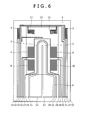
- Fig. 6 is a diagram showing a plane structure of a flow rate detecting element of a flow rate sensor according to a third embodiment of the present invention.
- Fig. 7 is a diagram showing a circuit configuration of the flow rate sensor according to the third embodiment of the present invention. According to the third embodiment, the arrangement of the plane detecting resistors 11 and 12 according to the first embodiment is changed.
- the strain detecting resistors 11 and 12 are arranged among the bonding terminals 14 through 32 which are used for connecting the temperature sensing resistors 7 through 10 to the external terminals
- the strain detecting resistors 11 and 12 are arranged on the diaphragm 13 on a side opposed to the bonding terminals 14 through 18, 20 through 25, and 27 through 32 with the temperature sensing resistors 7 through 10 as references.
- the third embodiment is similar to the first embodiment in the circuit operation. The present embodiment achieves an effect in a case where also the side opposed to the side of the bonding terminals is adhered to mount when the detecting element 1 is mounted to a supporter 60 ( Fig. 9 ).
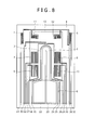
- Fig. 8 is a diagram showing a plane structure of a flow rate detecting element of a flow rate sensor according to a fourth embodiment of the present invention.
- the arrangement of the plane detecting resistors 11 and 12 according to the second embodiment is changed.
- the strain detecting resistors 11 and 12 are arranged among the bonding terminals 14 through 32 which are used for connecting the temperature sensing resistors 7 through 10 to the external terminals
- the strain detecting resistors 11 and 12 are arranged on the diaphragm 13 on the side opposed to the bonding terminals 14 through 18, 20 through 25, and 27 through 32 with the temperature sensing resistors 7 through 10 as references.
- the present embodiment also achieves an effect in a situation similar to that of the third embodiment.
- Fig. 9 is a diagram showing a stress effect when the detecting element 1 of a flow rate sensor according to an embodiment of the present invention is mounted on the supporter 60.
- the detecting element 1 is adhered to a concave portion 61 (cavity) which is formed at the supporter 60 by an adhesive agent 62.
- a stress is applied to the detecting element 1 from the supporter 60 and the adhesive agent 62 by a change in a environment temperature or the like, the diaphragm 13 on the detecting element 1 is deformed into a concave or convex shape, and the deformation is detected by the strain detecting resistors 11 and 12.
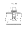
- Fig. 10 is a schematic sectional view of mounting a flow rate sensor according to the present invention in an actually used state.
- a flow rate sensor 51 is mounted in the form of being inserted into an intake pipe 59, and is fixed to the intake pipe 59 by a flange 27.
- a housing 52 is attached with the supporter 60 which is mounted with the detecting element 1 and the ASIC circuit 35.
- An air flow 56 flowing in the intake pipe 59 is shunted into the flow rate sensor 51 by an air inlet port 53, detours above the detecting element 1 by passing a bypass passage 55 and is returned into the main intake pipe 59 from a passage outlet 54.
Landscapes
- Physics & Mathematics (AREA)
- Fluid Mechanics (AREA)
- General Physics & Mathematics (AREA)
- Measuring Volume Flow (AREA)
Abstract
Description
- The present invention relates to a flow rate sensor which measures a flow rate by using a heat generating resistor. For example, the present invention relates to a flow rate measuring device which detects an amount of air that is sucked to an automobile engine.
- In a background art, as a flow rate sensor which is installed at a suction air passage of an internal combustion engine of an automobile or the like for measuring a suction air amount, a thermal type one is mainly used. This is because a thermal type flow rate sensor can directly measure a mass flow rate.
- In recent years, low fuel consumption and exhaust gas regulation are becoming severe from a view point of global environment protection. Therefore, in a flow rate sensor which measures a suction air amount, there are manifested needs for high accuracy, backflow detection, dynamic range expansion, and suchlike.
- In a thermal type flow rate sensor which deals with such needs, in recent years, attention is paid to fabricate a sensing element which measures a flow rate on a semiconductor substrate of silicon or the like by using a semiconductor microfabrication technology. Because a sensing element of this kind can comparatively easily be mass-produced, and therefore, the sensing element is excellent in economy, can be downsized and can be driven by low power consumption. As such a flow rate sensor, there is a flow rate sensor described in
Patent Literature 1. - In the case of the flow rate sensor described in
Patent Literature 1, the sensing element is formed with a sensing resistor on a silicon substrate via an insulating layer, and formed with a thin film portion (diaphragm portion) by removing a portion of the silicon substrate in order to thermally insulate the resistor. A heat generating resistor can be formed by arranging a resistor which is driven as a heater at the diaphragm portion. In detecting a flow rate, there is adopted a temperature difference system in which temperature sensing resistors are formed on an upstream side and on a downstream side of an air flow by interposing the heat generating resistor, and a flow rate and a direction are detected based on a difference between temperatures of the temperature sensing resistors that are arranged on the upstream side and on the downstream side. - Patent Literature 1: Japanese Unexamined Patent Publication No.
2002-48616 - In
Patent Literature 1, polysilicon is adopted for the resistor. A semiconductor material such as polysilicon has a piezoresistive effect in which a resistance value of the material is changed owing to a strain that is generated by deforming a shape of the material. An amount of influence of the piezoresistive effect is determined by a gauge factor of the material and the influence is effected even on a metal material of platinum or the like. Therefore, the semiconductor type flow rate sensor poses a problem that an abnormal output is easy to be brought about owing to the piezoresistive effect. - Hence, it is an object of the present invention that even when a strain is produced at a diaphragm portion of a substrate that is installed with a heater resistor and a temperature sensing resistor, a variation in a signal of a bridge circuit connected with the temperature sensing resistor that is caused by the strain is reduced. Solution to Problem
- The object described is achieved by an invention described in claims.
- For example, the object described above can be achieved by providing a structure as follows to a thermal type flow rate sensor including a substrate, a diaphragm formed at the substrate, and a heat generating resistor and a temperature detecting resistor formed on the diaphragm, and detecting a flow rate of a measured fluid by heating the heat generating resistor. Strain detecting resistors are formed on an upstream side and on a downstream side of a flow of the measured fluid relative to the heat generating resistor on the diaphragm. An amount of a strain generated on the diaphragm is detected by the strain detecting resistors, and a flow rate signal detected by the heat generating resistor and the temperature detecting resistor is compensated for the strain based on the amount of the strain detected. An amount of a strain effect can be removed and an abnormal output can be made difficult to be brought about by the compensation.
- According to the present invention, even when a strain is generated at a diaphragm portion of a substrate installed with a heater resistor and a temperature sensing resistor, a signal variation of a bridge circuit connected with a temperature sensing resistor caused by the strain can be reduced.
-
-
Fig. 1 is a diagram of a pattern of a sensing element of a flow rate sensor according to a first embodiment of the present invention. -
Fig. 2 is a diagram of a configuration of a circuit of the flow rate sensor according to the first embodiment of the present invention. -
Fig. 3 is a diagram showing an operation processing at inside of the flow rate sensor according to the first embodiment of the present invention. -
Fig. 4 is a diagram of a pattern of a sensing element of a flow rate sensor according to a second embodiment of the present invention. -
Fig. 5 is a diagram of a configuration of a circuit of a flow rate sensor according to the second embodiment of the present invention. -
Fig. 6 is a diagram of a pattern of a sensing element sensor of a flow rate sensor according to a third embodiment of the present invention. -
Fig. 7 is a diagram of a configuration of a circuit of the flow rate sensor according to the third embodiment of the present invention. -
Fig. 8 is a diagram of a pattern of a sensing element of a flow rate sensor according to a fourth embodiment of the present invention. -
Fig. 9 is a view showing an influence of a stress in mounting which is effected on a flow rate sensor according to an embodiment of the present invention. -
Fig. 10 is a schematic sectional view of mounting a flow rate sensor according to an embodiment of the present invention in an actually used state. - As described above, the semiconductor flow rate sensor poses a problem that an abnormal output owing to the piezoresistive effect is easy to be brought about. The reason is that a film thickness of the diaphragm portion is only about 1 through 2 µm, and therefore, the diaphragm portion undergoes (1) a stress when the sensing element is adhered to a supporter, (2) a stress when the supporter is adhered to be mounted on a casing or the like, (3) a stress which is generated from a difference of linear expansion coefficients of mounting members that is generated by a change in an environmental temperature, and (4) various deformations of a thermal deformation and the like that are brought about by making a heater generate heat.
- Particularly, it is preferable that the temperature sensing resistors which are formed by interposing a heater have high resistance values in view of performances thereof. Therefore, it is necessary to form the resistor such that a width of the resistor is slender and a length thereof is prolonged as a shape thereof. Therefore, the temperature sensing resistors are easy to undergo the piezoresistive effect by the stresses described above. As a result thereof, there is a possibility that the temperature sensing resistors formed by interposing the heater have resistance values respectively different from each other and an abnormal output is generated. Further, also the heater temperature detecting resistor needs to be arranged at a vicinity of the heater resistor, and it is necessary to form the heater temperature detecting resistor such that a width thereof is slender and a length thereof is prolonged similar to the temperature sensing resistor described above. As a result thereof, a resistance value of the heater temperature detecting resistor is changed, and a temperature of the heater cannot correctly be detected. As a result thereof, there is a possibility that the temperature of the heater cannot be controlled to a prescribed temperature and the abnormal output is brought about.
- An explanation will be given of embodiments of the present invention in reference to
Fig. 1 through Fig. 10 as follows. -
Fig. 1 is a diagram showing a plane structure of a flow rate detecting element of a flow rate sensor according to a first embodiment of the present invention. - In
Fig. 1 , a detectingelement 1 is formed with a cavity portion at a back face of a substrate which is configured by a material that is excellent in a heat conductivity of silicon, ceramic or the like and the cavity portion is formed with adiaphragm 13 for detecting a flow rate of air. The cavity portion is formed by etching from the back face side of the substrate by an alkaline solvent or the like. Aheater resistor 2 which is a resistor for setting a flow rate is arranged on thediaphragm 13, and a heatertemperature detecting resistor 3 is arranged to surround a surrounding of theheater resistor 2. Upstream sidetemperature sensing resistors temperature sensing resistors heater resistor 2.Strain detecting resistors diaphragm 13 amongbonding terminals 14 through 32 which are used for connecting thetemperature sensing resistors 7 through 10 and external terminals. - Fixed
resistors temperature measuring resistor 4 are formed on the substrate at a surrounding of thediaphragm 13. The resistors configured on the detectingelement 1 are made by a semiconductor film of polysilicon or the like and a metal film of platinum or the like resistance values of which are changed by a temperature. These elements are connected to outside by thebonding terminals 14 through 32. Thereby, an influence of a strain that is generated at the resistor on thediaphragm 13 can be excluded, or there can be provided a flow rate output in which a stress that is generated by the strain is alleviated. - Incidentally, all of the
heater resistor 2 and the heatertemperature detecting resistor 3, the upstream sidetemperature sensing resistors resistors strain detecting resistors fixed resistors temperature measuring resistor 4 are configured by the same material. Thereby, there can be configured a flow rate sensor which can provide a flow rate output excluding an influence of a strain that is generated at the resistor on thediaphragm 13 in mounting the diaphragm or the like without increasing cost. -
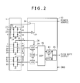
Fig. 2 is a diagram showing a configuration of a circuit of the flow rate sensor according to the first embodiment of the present invention. - In
Fig. 2 , the flow rate sensor includes the detectingelement 1 which detects an air flow rate, an air temperature, and a strain amount that is generated at thediaphragm 13, and anASIC circuit 35 for converting the air flow rate and the strain amount into electric signals and adjusting the air flow rate excluding the strain amount to a prescribed characteristic. - A
power source 38 is connected to a bridge circuit formed by the heatertemperature detecting resistor 3, thetemperature measuring resistor 4, and the fixedresistors bonding terminal 25 showing a potential of a connection point of the heatertemperature detecting resistor 3 and the fixedresistor 6, and thebonding terminal 31 showing a potential of a connection point of thetemperature measuring resistor 4 and the fixedresistor 5 are connected to an input terminal of anoperational amplifier 37. Theoperational amplifier 47 controls a heating current which is supplied to theheater resistor 2 by a feedback control such that these potentials become the same. Here, the heating current is supplied by atransistor 36 which is controlled by theoperational amplifier 37. - The
power source 38 is connected to a bridge circuit which is arranged on an upstream side of a flow direction of air relative to theheater resistor 2. The bridge circuit is formed by thetemperature sensing resistors temperature sensing resistors heater resistor 2, resistance values of which are changed by an influence of heat from theheater resistor 2. - The
power source 38 is also connected to a bridge circuit which is formed by thestrain detecting resistors diaphragm 13, and fixedresistors - With regard to a differential signal in correspondence with an air flow rate, the bonding terminal 16 (or 28) indicating a potential at a connection point of the
temperature sensing resistors temperature sensing resistors A-D converter 39. Also, with regard to a differential signal in correspondence with an amount of a strain generated at thediaphragm 13, thebonding terminal 20 indicating a potential at a connection point of thestrain detecting resistor 11 and the fixedresistor 33, and thebonding terminal 27 indicating a potential at a connection point of thestrain detecting resistor 12 and the fixedresistor 34 are connected to anA-D converter 40. Outputs of theA-D converters DSP 42. AtDSP 42, the amount of the strain generated at thediaphragm 13 is compensated for, adjusted to a prescribed characteristic, and outputted by using adjustment information stored atROM 41. The adjusted flow rate signal is inputted to aD-A converter 43 or a frequency output converter (FRC) 44, and is converted into a voltage signal or a frequency signal. Finally, the voltage signal or the frequency signal is outputted as a flow rate output by a multiplexer (MPX) 45 which is a change-over switch based on information stored inROM 41. - As shown in
Fig. 2 , theASIC circuit 35 is configured by theoperational amplifier 37, thepower source 38, thetransistor 36, theA-D converters ROM 41,DSP 42, theD-A converter 43, and the multiplexer (MPX) 45. - By the
ASIC circuit 35, there is obtained an output in which an output of the bridge circuit which is formed by the upstream sidetemperature sensing resistors heat resistor 2, and the downstream sidetemperature sensing resistors heater resistor 2, resistance values of which are changed by an effect of heat from theheater resistor 2 and the output is compensated for a strain effect. In this way, an abnormal output is made difficult to be brought about by removing an amount of the strain effect from the output of the bridge circuit. -
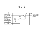
Fig. 3 is a diagram indicating an operation processing executed at inside ofDSP 42 at inside of theASIC circuit 35 of the flow rate sensor according to the first embodiment of the present invention. - In
Fig. 3 , a signal detected at astrain detecting unit 47 is very small, and therefore, the signal is multiplied by a prescribed gain at anoperator 48. Thereafter, a strain detecting signal as amplified, and a strain amount at an initial state which is previously written toROM 41 are inputted to anoperator 49, where a difference therebetween is calculated. A net strain amount is calculated by the calculation. An output from a flowrate detecting unit 46 and a strain detecting signal which is calculated by theoperator 49 are inputted to anoperator 50, where a prescribed operation is executed and a true flow rate detecting signal is outputted. -
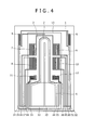
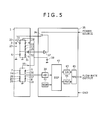
Fig. 4 is a diagram showing a plane structure of a flow rate detecting element of a flow rate sensor according to a second embodiment of the present invention. Also,Fig. 5 is a diagram showing a circuit configuration of the flow rate sensor according to the second embodiment of the present invention. According to the second embodiment, thepower source 48 is connected to a bridge circuit which is formed by the heatertemperature detecting resistor 3, thetemperature measuring resistor 4, the fixedresistors strain detecting resistors bonding terminal 25 indicating the potential at the connection point of the heatertemperature detecting resistor 3 and the fixedresistor 6, and thebonding terminal 31 indicating the potential at the connection point of thetemperature measuring resistor 4 and the fixedresistor 5 are inputted to the input terminals of theoperational amplifier 37. Theoperational amplifier 37 controls the heating temperature supplied to theheater resistor 2 by a feedback control such that these potentials are equal to each other. Here, the heating temperature is supplied by thetransistor 36 controlled by theoperational amplifier 37. - Here, an explanation will be given of a method of excluding an influence of the strain from the flow rate output when the strain is generated at the
diaphragm 13. As described above, theoperational amplifier 37 controls the heating current by the feedback control such that the potential at the input terminal stays the same. The following relationship can be derived from the feedback control. When it is designated that the heater temperature detecting resistor 3: Rht, the temperature measuring resistor 4: Rc, the fixed resistor 5: R7, the fixed resistor 5: R1, the strain detecting resistor 11: Rp1, and the strain detecting resistor 12: Rp2,
When the relationship is developed with regard to Rht by putting Rp = Rp1 + Rp2, Rht = R1/R7 · (Rc + Rp)
Here, when a resistance of the resistor on the diaphragm is changed by a mounting stress or the like, it can be derived as follows.
Here, a change in a resistance by a strain is generally represented by the following equation. -

(K: gage factor, ε: strain)
Thereby, the strain detecting resistor Rp may be set as follows. -


The influence by the strain of the heater temperature control bridge can be excluded when the strain is generated at thediaphragm 13 by setting the strain detecting resistor as described above. - With regard to the differential signal in correspondence with the air flow rate, the bonding terminal 16 (or 28) indicating the potential at the connection point of the
temperature sensing resistors temperature sensing resistors A-D converter 39. The output of theA-D converter 39 is inputted toDSP 42. AtDSP 42, the output is adjusted to a prescribed characteristic and outputted by using the adjustment information stored toROM 41. The flow rate signal as adjusted is inputted to theD-A converter 43 or the frequency output converter (FRC) 44, and converted into the voltage signal or the frequency signal. Finally, the voltage signal or the frequency signal is outputted as the flow rate output by the multiplexer (MPX) 45 which is the change-over switch based on the information stored toROM 41. - The compensation of the stress effect can be provided to the bridge circuit controlling the heater
temperature detecting resistor 3 at a constant temperature by configuring the bridge circuit by the heatertemperature detecting resistor 3, thetemperature measuring resistor 4, the fixedresistors strain detecting resistors -
Fig. 6 is a diagram showing a plane structure of a flow rate detecting element of a flow rate sensor according to a third embodiment of the present invention. Also,Fig. 7 is a diagram showing a circuit configuration of the flow rate sensor according to the third embodiment of the present invention. According to the third embodiment, the arrangement of theplane detecting resistors strain detecting resistors bonding terminals 14 through 32 which are used for connecting thetemperature sensing resistors 7 through 10 to the external terminals, according to the third embodiment, thestrain detecting resistors diaphragm 13 on a side opposed to thebonding terminals 14 through 18, 20 through 25, and 27 through 32 with thetemperature sensing resistors 7 through 10 as references. The third embodiment is similar to the first embodiment in the circuit operation. The present embodiment achieves an effect in a case where also the side opposed to the side of the bonding terminals is adhered to mount when the detectingelement 1 is mounted to a supporter 60 (Fig. 9 ). -
Fig. 8 is a diagram showing a plane structure of a flow rate detecting element of a flow rate sensor according to a fourth embodiment of the present invention. According to the fourth embodiment, the arrangement of theplane detecting resistors strain detecting resistors bonding terminals 14 through 32 which are used for connecting thetemperature sensing resistors 7 through 10 to the external terminals, according to the fourth embodiment, thestrain detecting resistors diaphragm 13 on the side opposed to thebonding terminals 14 through 18, 20 through 25, and 27 through 32 with thetemperature sensing resistors 7 through 10 as references. The present embodiment also achieves an effect in a situation similar to that of the third embodiment. -
Fig. 9 is a diagram showing a stress effect when the detectingelement 1 of a flow rate sensor according to an embodiment of the present invention is mounted on thesupporter 60. The detectingelement 1 is adhered to a concave portion 61 (cavity) which is formed at thesupporter 60 by anadhesive agent 62. Here, it is shown that when a stress is applied to the detectingelement 1 from thesupporter 60 and theadhesive agent 62 by a change in a environment temperature or the like, thediaphragm 13 on the detectingelement 1 is deformed into a concave or convex shape, and the deformation is detected by thestrain detecting resistors -
Fig. 10 is a schematic sectional view of mounting a flow rate sensor according to the present invention in an actually used state. - In
Fig. 10 , aflow rate sensor 51 is mounted in the form of being inserted into anintake pipe 59, and is fixed to theintake pipe 59 by aflange 27. Ahousing 52 is attached with thesupporter 60 which is mounted with the detectingelement 1 and theASIC circuit 35. - An
air flow 56 flowing in theintake pipe 59 is shunted into theflow rate sensor 51 by anair inlet port 53, detours above the detectingelement 1 by passing abypass passage 55 and is returned into themain intake pipe 59 from apassage outlet 54. -
- 1
- detecting element
- 2
- heater resistor
- 3
- heater temperature detecting resistor
- 4
- temperature measuring resistor
- 5, 6, 33, 34
- fixed resistors
- 7, 8
- upstream side temperature sensing resistors
- 9, 10
- downstream side temperature sensing resistors
- 11, 12
- strain detecting resistors
- 13
- diaphragm
- 14 to 32
- bonding terminals
- 35
- ASIC circuit
- 36
- transistor
- 37
- operational amplifier
- 38
- power source
- 39, 40
- A-D converters
- 41
- ROM
- 42
- DSP
- 43
- D-A converter
- 44
- frequency output converting circuit (FRC)
- 45
- multiplexer (MPX)
- 46
- flow rate detecting unit
- 47
- strain detecting unit
- 48 to 50
- operators
- 51
- flow rate sensor
- 52
- housing
- 53
- air inlet port
- 54
- passage outlet
- 55
- bypass passage
- 56
- air flow
- 57
- flange
- 58
- base
- 59
- intake pipe
- 60
- supporter
- 61
- cavity
- 62
- adhesive agent
Claims (9)
- A thermal type flow rate sensor comprising a substrate, a diaphragm formed at the substrate, and a heat generating resistor and a temperature detecting resistor formed on the diaphragm, and detecting a flow rate of a measured fluid by heating the heat generating resistor;
wherein strain detecting resistors are formed on an upstream side and on a downstream side of a flow of the measured fluid relative to the heat generating resistor on the diaphragm;
wherein an amount of a strain generated on the diaphragm is detected by the strain detecting resistor; and
wherein a flow rate signal detected by the heat generating resistor and the temperature detecting resistor is compensated for the strain based on the detected amount of the strain. - The thermal type flow rate sensor according to claim 1,
wherein the strain detecting resistor is electrically connected to the heat generating resistor and the temperature detecting resistor,
and
wherein a compensation for a stress effect is provided to a bridge circuit controlling the heat generating resistor at a constant temperature. - The thermal type flow rate sensor according to claim 1,
wherein the strain detecting resistor is arranged between a bonding pad for electrically connecting to an external terminal and the temperature detecting resistor. - The thermal type flow rate sensor according to claim 1,
wherein the strain detecting resistor is formed by polysilicon or a diffused resistor. - The thermal type flow rate sensor according to claim 1, comprising:a first A-D converter of inputting an output of a bridge circuit configured by the strain detecting resistor and a fixed resistor;a second A-D converter of inputting an output from a bridge circuit configured by the temperature detecting resistor; anda memory previously stored with a piece of adjustment information,wherein the output of the bridge circuit configured by the temperature detecting resistor is compensated for the amount of the strain generated on the diaphragm detected by the strain detecting resistor.
- The thermal type flow rate sensor according to claim 1,
wherein a bridge circuit is configured by the heat generating resistor, the temperature detecting resistor, and the strain detecting resistor, and the heat generating resistor is controlled to be controlled at a constant temperature. - The thermal type flow rate sensor according to claim 1,
wherein the strain detecting resistors are arranged respectively in a longitudinal direction and a transverse direction of the diaphragm. - The thermal type flow rate sensor according to claim 1,
wherein the strain detecting resistor is arranged on a side opposed to a bonding pad of connecting the temperature detecting resistor and an external terminal. - The thermal type flow rate sensor according to claim 1,
wherein the heat generating resistor, the temperature detecting resistor, and the strain detecting resistor are configured by the same material.
Applications Claiming Priority (2)
| Application Number | Priority Date | Filing Date | Title |
|---|---|---|---|
| JP2010084784A JP5542505B2 (en) | 2010-04-01 | 2010-04-01 | Thermal flow sensor |
| PCT/JP2011/058391 WO2011125923A1 (en) | 2010-04-01 | 2011-04-01 | Thermal flow sensor |
Publications (2)
| Publication Number | Publication Date |
|---|---|
| EP2554953A1 true EP2554953A1 (en) | 2013-02-06 |
| EP2554953A4 EP2554953A4 (en) | 2015-01-21 |
Family
ID=44762861
Family Applications (1)
| Application Number | Title | Priority Date | Filing Date |
|---|---|---|---|
| EP11765823.7A Withdrawn EP2554953A4 (en) | 2010-04-01 | 2011-04-01 | THERMAL FLOW SENSOR |
Country Status (5)
| Country | Link |
|---|---|
| US (1) | US8935959B2 (en) |
| EP (1) | EP2554953A4 (en) |
| JP (1) | JP5542505B2 (en) |
| CN (1) | CN102822641B (en) |
| WO (1) | WO2011125923A1 (en) |
Cited By (1)
| Publication number | Priority date | Publication date | Assignee | Title |
|---|---|---|---|---|
| CN111684240A (en) * | 2018-02-16 | 2020-09-18 | 日立汽车系统株式会社 | Semiconductor element and flow measurement device using the same |
Families Citing this family (7)
| Publication number | Priority date | Publication date | Assignee | Title |
|---|---|---|---|---|
| DE102011002947B3 (en) * | 2011-01-20 | 2012-01-26 | Siemens Aktiengesellschaft | Measuring arrangement with arranged in gas paths electrically heated resistors |
| JP5904959B2 (en) | 2013-03-08 | 2016-04-20 | 日立オートモティブシステムズ株式会社 | Thermal air flow meter |
| JP5968279B2 (en) * | 2013-08-01 | 2016-08-10 | 日立オートモティブシステムズ株式会社 | Thermal flow meter |
| KR101581134B1 (en) * | 2013-10-28 | 2015-12-29 | 니혼 덴산 산쿄 가부시키가이샤 | Sensor device |
| WO2016084664A1 (en) * | 2014-11-28 | 2016-06-02 | 日立オートモティブシステムズ株式会社 | Thermal-type flow rate sensor |
| US20160370809A1 (en) * | 2015-06-19 | 2016-12-22 | Hni Technologies Inc. | Fluid flow system |
| US11402253B2 (en) * | 2018-06-26 | 2022-08-02 | Minebea Mitsumi Inc. | Fluid sensing apparatus and method for detecting failure of fluid sensor |
Family Cites Families (15)
| Publication number | Priority date | Publication date | Assignee | Title |
|---|---|---|---|---|
| DE3637541A1 (en) * | 1986-11-04 | 1988-05-05 | Vdo Schindling | DEVICE FOR DETERMINING THE MASS CURRENT AND THE FLOW DIRECTION |
| US4884443A (en) * | 1987-12-23 | 1989-12-05 | Siemens-Bendix Automotive Electronics L. P. | Control and detection circuitry for mass airflow sensors |
| JPH0637334A (en) * | 1992-07-16 | 1994-02-10 | Copal Electron Co Ltd | Structure of pressure sensor |
| JP2002048616A (en) * | 2000-08-07 | 2002-02-15 | Hitachi Ltd | Thermal air flow sensor and internal combustion engine controller |
| US6631638B2 (en) * | 2001-01-30 | 2003-10-14 | Rosemount Aerospace Inc. | Fluid flow sensor |
| US6647778B2 (en) * | 2001-06-20 | 2003-11-18 | Integrated Sensing Systems | Integrated microtube sensing device |
| JP2003106887A (en) * | 2001-09-28 | 2003-04-09 | Yamatake Corp | Flow measurement device |
| US6901794B2 (en) * | 2003-10-16 | 2005-06-07 | Festo Corporation | Multiple technology flow sensor |
| JP2005241279A (en) * | 2004-02-24 | 2005-09-08 | Fujikin Inc | Sensor made of anti-corrosion metal for fluid and fluid supply apparatus |
| JP4881554B2 (en) * | 2004-09-28 | 2012-02-22 | 日立オートモティブシステムズ株式会社 | Flow sensor |
| US7171851B2 (en) * | 2004-12-28 | 2007-02-06 | Schlumberger Technology Corporation | Temperature compensated strain measurement |
| JP2007024589A (en) * | 2005-07-13 | 2007-02-01 | Hitachi Ltd | Gas flow measuring device |
| JP4797771B2 (en) * | 2006-04-20 | 2011-10-19 | 株式会社デンソー | SENSOR DEVICE HAVING MEMBRANE AND MANUFACTURING METHOD THEREOF |
| JP2008170382A (en) * | 2007-01-15 | 2008-07-24 | Hitachi Ltd | Thermal fluid flow sensor and manufacturing method thereof |
| JP5276964B2 (en) * | 2008-12-08 | 2013-08-28 | 日立オートモティブシステムズ株式会社 | Thermal fluid flow sensor and manufacturing method thereof |
-
2010
- 2010-04-01 JP JP2010084784A patent/JP5542505B2/en not_active Expired - Fee Related
-
2011
- 2011-04-01 WO PCT/JP2011/058391 patent/WO2011125923A1/en not_active Ceased
- 2011-04-01 CN CN201180017273.1A patent/CN102822641B/en not_active Expired - Fee Related
- 2011-04-01 US US13/638,259 patent/US8935959B2/en active Active
- 2011-04-01 EP EP11765823.7A patent/EP2554953A4/en not_active Withdrawn
Cited By (2)
| Publication number | Priority date | Publication date | Assignee | Title |
|---|---|---|---|---|
| CN111684240A (en) * | 2018-02-16 | 2020-09-18 | 日立汽车系统株式会社 | Semiconductor element and flow measurement device using the same |
| CN111684240B (en) * | 2018-02-16 | 2022-03-08 | 日立安斯泰莫株式会社 | Semiconductor element and flow rate measuring device using the same |
Also Published As
| Publication number | Publication date |
|---|---|
| JP5542505B2 (en) | 2014-07-09 |
| US20130025363A1 (en) | 2013-01-31 |
| US8935959B2 (en) | 2015-01-20 |
| WO2011125923A1 (en) | 2011-10-13 |
| EP2554953A4 (en) | 2015-01-21 |
| CN102822641B (en) | 2016-05-18 |
| JP2011215062A (en) | 2011-10-27 |
| CN102822641A (en) | 2012-12-12 |
Similar Documents
| Publication | Publication Date | Title |
|---|---|---|
| US8935959B2 (en) | Thermal type flow rate sensor | |
| US9958305B2 (en) | Gas sensor device | |
| EP3199934B1 (en) | Pressure change measurement device, altitude measurement device, and pressure change measurement method | |
| EP3153833B1 (en) | Dynamic quantity measuring device and pressure sensor using same | |
| US10393608B2 (en) | Pressure change measuring apparatus and pressure change measuring method | |
| EP1698864B1 (en) | Thermal flowmeter of fluid | |
| CN105008870B (en) | Heat type fluid measuring device | |
| US6901794B2 (en) | Multiple technology flow sensor | |
| EP1418408B1 (en) | Thermal flow sensor | |
| JP4850105B2 (en) | Thermal flow meter | |
| JP7168340B2 (en) | thermal flow meter | |
| WO2012032917A1 (en) | Gas flow rate measurement device | |
| US7287424B2 (en) | Thermal type flow measurement apparatus having asymmetrical passage for flow rate measurement | |
| EP2966417B1 (en) | Thermal-type airflow meter | |
| JP5120289B2 (en) | Air flow measurement device | |
| JPH10197316A (en) | Density corrected liquid level detector | |
| JP2004226289A (en) | Thermal air flow measuring device and diagnostic method therefor | |
| JP2002174541A (en) | Thermal flow meter | |
| JP2019066253A (en) | Flow rate measuring device | |
| JP4089657B2 (en) | Air flow sensor | |
| JP3144943B2 (en) | Air flow measurement device | |
| JP2000180231A (en) | Flow measurement method, flow sensor, compound flow meter | |
| JPH0835874A (en) | Flowmeter |
Legal Events
| Date | Code | Title | Description |
|---|---|---|---|
| PUAI | Public reference made under article 153(3) epc to a published international application that has entered the european phase |
Free format text: ORIGINAL CODE: 0009012 |
|
| 17P | Request for examination filed |
Effective date: 20121102 |
|
| AK | Designated contracting states |
Kind code of ref document: A1 Designated state(s): AL AT BE BG CH CY CZ DE DK EE ES FI FR GB GR HR HU IE IS IT LI LT LU LV MC MK MT NL NO PL PT RO RS SE SI SK SM TR |
|
| DAX | Request for extension of the european patent (deleted) | ||
| A4 | Supplementary search report drawn up and despatched |
Effective date: 20141219 |
|
| RIC1 | Information provided on ipc code assigned before grant |
Ipc: G01F 25/00 20060101ALI20141215BHEP Ipc: G01F 1/692 20060101AFI20141215BHEP Ipc: G01F 1/696 20060101ALI20141215BHEP |
|
| STAA | Information on the status of an ep patent application or granted ep patent |
Free format text: STATUS: THE APPLICATION IS DEEMED TO BE WITHDRAWN |
|
| 18D | Application deemed to be withdrawn |
Effective date: 20150723 |