EP2554755A1 - Floor drainage system - Google Patents
Floor drainage system Download PDFInfo
- Publication number
- EP2554755A1 EP2554755A1 EP11176440A EP11176440A EP2554755A1 EP 2554755 A1 EP2554755 A1 EP 2554755A1 EP 11176440 A EP11176440 A EP 11176440A EP 11176440 A EP11176440 A EP 11176440A EP 2554755 A1 EP2554755 A1 EP 2554755A1
- Authority
- EP
- European Patent Office
- Prior art keywords
- mounting frame
- adapter plate
- tub
- drainage system
- floor drainage
- Prior art date
- Legal status (The legal status is an assumption and is not a legal conclusion. Google has not performed a legal analysis and makes no representation as to the accuracy of the status listed.)
- Granted
Links
- 238000004891 communication Methods 0.000 claims abstract description 4
- 238000007789 sealing Methods 0.000 claims description 22
- XLYOFNOQVPJJNP-UHFFFAOYSA-N water Substances O XLYOFNOQVPJJNP-UHFFFAOYSA-N 0.000 claims description 19
- 230000005484 gravity Effects 0.000 claims description 13
- 238000009434 installation Methods 0.000 claims description 8
- 230000001070 adhesive effect Effects 0.000 claims description 7
- 239000000565 sealant Substances 0.000 claims description 7
- 239000000853 adhesive Substances 0.000 claims description 6
- 125000006850 spacer group Chemical group 0.000 claims description 4
- 239000003673 groundwater Substances 0.000 abstract 1
- 229910000831 Steel Inorganic materials 0.000 description 4
- 239000010959 steel Substances 0.000 description 4
- 229920001296 polysiloxane Polymers 0.000 description 3
- NIXOWILDQLNWCW-UHFFFAOYSA-N acrylic acid group Chemical group C(C=C)(=O)O NIXOWILDQLNWCW-UHFFFAOYSA-N 0.000 description 2
- 238000005452 bending Methods 0.000 description 2
- 210000003298 dental enamel Anatomy 0.000 description 2
- 239000004590 silicone sealant Substances 0.000 description 2
- 150000001875 compounds Chemical class 0.000 description 1
- 238000010276 construction Methods 0.000 description 1
- 230000001419 dependent effect Effects 0.000 description 1
- 230000000694 effects Effects 0.000 description 1
- 238000004519 manufacturing process Methods 0.000 description 1
- 239000000463 material Substances 0.000 description 1
- 239000002184 metal Substances 0.000 description 1
- 230000002093 peripheral effect Effects 0.000 description 1
- 239000007787 solid Substances 0.000 description 1
- 239000007921 spray Substances 0.000 description 1
- 230000007704 transition Effects 0.000 description 1
Images


Classifications
-
- E—FIXED CONSTRUCTIONS
- E03—WATER SUPPLY; SEWERAGE
- E03F—SEWERS; CESSPOOLS
- E03F5/00—Sewerage structures
- E03F5/04—Gullies inlets, road sinks, floor drains with or without odour seals or sediment traps
-
- E—FIXED CONSTRUCTIONS
- E03—WATER SUPPLY; SEWERAGE
- E03C—DOMESTIC PLUMBING INSTALLATIONS FOR FRESH WATER OR WASTE WATER; SINKS
- E03C1/00—Domestic plumbing installations for fresh water or waste water; Sinks
- E03C1/12—Plumbing installations for waste water; Basins or fountains connected thereto; Sinks
- E03C1/22—Outlet devices mounted in basins, baths, or sinks
Definitions
- the present invention relates to a floor drain system according to the preamble of claim 1.
- Floor drainage systems for sanitary installations are known in the art. Such floor drain systems are used for the removal of water, for example from a shower tray or a shower surface.
- Such floor drain systems have the advantage that the floor surface on which the user can stand is executed without interruption, ie as a completely continuous surface. This is advantageous for the user, because tripping over protruding elements can be prevented. Furthermore, a gap must be provided between the drainage system installed in the wall and the floor surface, which may also include the transition to corresponding tiles.
- the main advantage of such systems is that a floor-level surface can be formed without joints or drainage holes in the surface.
- the present invention seeks to provide a floor drain system, which overcomes the disadvantages of the prior art.
- the floor drain system should be easier to assemble and to be as stress-free as possible during operation.
- the floor drain system comprises a mounting frame, an associated with the mounting frame drain unit with a drain channel, which is accessible via a drain opening, and a tub member with a standing area.
- the standing surface opens onto or into the drain opening, so that bottom water located on the standing surface can be fed to the drainage channel.
- the floor drain system comprises at least one fastening element for fastening the tub element to the mounting frame, so that a firm connection between the mounting frame and tub element is present.
- the tub element is preferably made of steel enamel or acrylic.
- the attachment of the tub element on the mounting frame has the advantage that a floor drain system is available, which is very easy to install.
- stresses between the mounting frame and the tub element can be largely avoided via the connection between the mounting frame and tub element.
- the fastening element has the shape of a material-locking connection, in particular the shape of an adhesive or a sealant.
- a fastener solves the problem of simple design of the overall construction and thus has the advantage that the fixed connection between the drain element and the tub element at the same time provides a sealing solution.
- the fastening element can also have the shape of a mechanical connection which engages directly or indirectly in the mounting frame.
- the said mechanical fastening element has, in particular, the shape of a screw which projects through an opening arranged in the tub element and engages in a thread which is directly or indirectly in connection with the mounting frame.
- the fastening element is designed such that forces can be absorbed in a substantially perpendicular direction to the force of gravity.
- This has the advantage that a good connection to the mounting frame is made possible while other forces in the direction of gravity, such as by supports or a direct support of the tub element on a floor can be compensated.
- the at least one fastening element is preferably connected directly to the mounting frame.
- the at least one fastening element is indirectly connected via at least one further element, such as an adapter plate and / or a panel to the mounting frame.
- the tub element comprises at least one mounting flange formed on the tub element, wherein the tub element is connected to the mounting frame via this mounting flange.
- the mounting flange has the advantage that this particular is easy to manufacture and also also allows easy installation.
- two mounting flanges spaced apart from each other are formed on the tub element, wherein the mounting flanges limit a flow passage through which the bottom water of the drain unit can be fed.
- the mounting flanges protrude upwards with respect to the standing surface the direction of gravity.
- the mounting flanges each have at least one optional opening, which serve to carry out the fastening element.
- another flange protrudes downwardly in the direction of gravity with respect to the standing surface, said flange preferably extending laterally across the flow passage.
- the mounting flanges and the further flange form a receiving surface for a sealing element or the fastening element.
- the mechanical fastening element has the shape of a mechanical connection, in particular the shape of a screw.
- the mechanical fastening element preferably projects through an opening in the fastening flange and engages in a thread that is directly or indirectly connected to the mounting frame.
- an adapter plate is arranged for indirect connection between the tub element and the mounting frame, wherein the adapter plate is fixedly connected to the mounting frame via connecting elements and wherein the at least one fastening element connects the tub element with the adapter plate.
- the adapter plate has threads for receiving the fastener in the shape of the screw, the threads preferably being provided by threaded nuts associated with the adapter plate.
- a panel having openings and a flow opening for providing a passageway for the bottom water, the connection members projecting through openings in the panel and parts of the drain unit projecting into a flow opening in the panel.
- said sealing element is arranged between the adapter plate and the flange.
- a further sealing element is arranged between the adapter plate and the panels.
- the sealing element for example, a be on the corresponding surface sprayed silicone sealant or a solid seal, such as a rubber seal.
- the adapter plate and / or the tub element have spacer elements which provide a defined gap between the adapter plate and the tub element, in which said seal can be arranged.
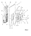
- FIGS. 1 and 2 an embodiment of a floor drain system 1 according to the present invention is shown.
- FIG. 1 are all elements of the floor drain system in the assembled state and in the FIG. 2 an exploded view is shown, in which the individual components are recognizable.
- the floor drainage system 1 for a sanitary installation essentially comprises a mounting frame 2, a drainage unit 3 with a drainage channel 4, which is accessible via a drainage opening 27, and a tubing element 5 with a standing surface 6.
- the standing surface 6 opens into or onto the drainage opening 27 , So that bottom water, which rests on the standing surface 6, the flow channel 4 can be fed and carried away over this.
- the standing surface 6 is arranged to the drain opening 27, that the Standing surface 6 is flush with a lower edge 18 of the drain opening 27.
- the standing surface opens via this lower edge 18 in the drain opening.
- the sanitary installation is a shower, with the tub member 5 then providing a shower tray.
- tray element used herein includes any element on which a user can stand, that is, a trough with peripheral side edges, or a trough in the shape of a metal sheet without circumferential side edges.
- the user of the shower stands on the standing surface 6 of the tub element 5.
- the shower water is as bottom water on this floor space 6 and is led away over the area from the shower to drain unit 2.
- the standing surface 6 with respect to the direction of gravity to the drain unit 2 towards preferably inclined, ie with a slope arranged.
- the mounting frame 1 is substantially perpendicular in a room and is arranged behind a wall, not shown here or provides with an optional panels 14 at the same time the wall itself.
- the panels 14 can be additionally covered with tiles.
- the trough element 5 extends at an angle to the mounting frame 1 and is located substantially at the level of a lower edge 18 of the drainage channel 4.
- the mounting frame 1 is formed here as a frame with two vertically extending supports 28 and a horizontally extending support 29. In the lower region, the drainage unit 4 is arranged between the two vertically extending supports 28.
- the floor drain system comprises at least one fastening element 7 for fastening the tub element 5 to the mounting frame 2. Consequently, the tub element 5 is fixedly connected to the mounting frame 2 by the at least one fastening element 7.
- This connection has the advantage that a firm connection between the mounting frame 2 and the tub element 5 can be provided, which ensures that the mounting frame 2 and the tub element 5 can be reproducibly aligned with each other and thus a simple assembly is provided. Next movements and thus stresses between the tub element 5 and mounting frame 2 can be avoided.
- the fastening element 7 is preferably designed such that these forces in the Run substantially perpendicular to the direction of gravity S, picking up.
- the fastening element 7 thus essentially serves to connect the tub element 5 to the mounting frame.
- the tub member 5 itself preferably rests on supports, not shown, on the floor, whereby the weight of the user standing on the tub member 5 is supported by these supports.
- the tub element 5 can also rest directly on the floor.
- the at least one fastening element 7 can communicate directly with the mounting frame 2.
- the fastening element 7 can also be connected to the mounting frame 2 via at least one further element, such as, for example, an adapter plate 12 and / or a panel 14.
- at least one further element such as, for example, an adapter plate 12 and / or a panel 14.
- the fastening element 7 may be formed mechanically and / or cohesively.
- the fastening element 7 is a screw which provides a mechanical connection between the tub element and the mounting frame 2.
- the fastening element 7 may also be an adhesive or a sealant.
- the tub member 5 preferably comprises at least one mounting flange 8 integrally formed on the tub element 5.
- the mounting flange 8 serves to fasten the tub element 5 to the mounting frame 2. Consequently, the tub element 5 is connected to the mounting frame 2 via this flange 8.
- the mounting flange 8 preferably protrudes upwards with respect to the standing surface 6 against the direction of gravity S. This allows good accessibility of the fastening flange 8 in order to mount the tub element 5.
- two mounting flanges 8 are spaced apart from each other and define a flow passage 19 through which the bottom water can reach the drainage channel 4.
- an optional further flange 9 is arranged here between the two fastening flanges 8, which flange extends in the other direction, that is to say from the standing surface in the direction of the force of gravity S.
- the further flange 9 extends here from a mounting flange 8 to the other Mounting flange 8 and has a greater length than the flow passage 19, so that the ends of the further flange 9 come to lie in the region of the mounting flanges 8.
- the further flange 9 not only has the effect as Abstützflansch but can also accommodate a sealing element, as will be explained below.
- the further flange 9 can, as it is in the FIG. 3 can be seen welded to the mounting flanges, the further flange 9 then also has a flow passage 19 corresponding recess must have.
- the fastening element 7 preferably has the shape of a screw 7, which projects through the openings 10 in the mounting flanges 8 and engages in a standing with the mounting frame 2 in conjunction thread 11.
- This thread 11 can either lie directly on the mounting frame 2 or be arranged on said other element.
- the fastening element 7 may also have the shape of an adhesive.
- the further element for the indirect connection between the tub element 5 and the mounting frame 2 preferably has the shape of an adapter plate 12, which is arranged between the mounting frame 2 and the tub element 5.
- the adapter plate 12 is connected via at least one connecting element 13, such as a screw and / or an adhesive or sealant with the mounting frame 2 in connection and the tub member 5 stands with the adapter plate 12 in connection. Consequently, the adapter plate 12 is fastened to the mounting frame 2 via the connecting element 13, and the tub element 5 is fastened to the mounting frame 2 via the fastening element 7.
- the adapter plate 12 can then be mounted to the mounting frame 2 and then the tub element 5 can be connected to the adapter plate 12. This is the indirect connection.
- the adapter plate 12 comprises for the mechanical connection between the tub element 5 and mounting frame 2, the thread 11.
- these are threaded nuts 11, which are in communication with the adapter plate 12.
- the adapter plate 12 further comprises openings 31 through which the connecting elements 13 can be passed.
- the connecting elements 13 are screws which are then threaded, which are arranged on the mounting frame 2, intervention.
- the adapter plate 12 further comprises a flow opening 21, which has substantially the same cross section as the flow passage 19. Further, the adapter plate 12 may also include a bending portion 30, which gives the adapter plate 12 an additional stability.
- a panel 14 may be arranged between the adapter plate 12 and mounting frame 2.
- the panels 14 have a multiplicity of openings 15 through which the connecting elements 13 can protrude through, so that they can be connected to the mounting frame 12.
- the panels 14 also include a flow opening 22, through which the water can be fed to the drainage channel 4. So now that the adapter plate 12 and panels 14 are arranged, the bottom water flows through the flow passage 19 and the two flow openings 21, 22 to the outlet channel 4 of the drain unit. 3
- All cross-sections through which the bottom water flows are preferably designed as rectangular cross-sections, which has the advantage that a lower edge 18 can be provided, through which the bottom water can flow.
- the lower edge 18 of all elements traversed by the bottom water is substantially at the level of the standing surface 6. Consequently, the lower edge 18 of the drain unit 3 is at the level of the standing surface 6.
- a sealing element 16 is preferably arranged between the adapter plate 12 and the tub member 5.
- the sealing element 16 extends on the mounting flanges 8 along the direction S and then over the further flange 9. Consequently, a continuous sealing line, which extends below the flow passage 19.
- the sealing element 20 is substantially identical to the sealing element 16 and also forms a continuous sealing line, which extends below the flow passage 19 and the flow opening 21.
- both sealing elements 16, 20 it is advantageous that these are around the Flow passage 19 and extend to the flow opening 21 in the adapter plate 12, so that no water between the adapter plate 12 and tub element 5 or panels 14 can pass.
- spacer holding elements 17 are arranged, which creates a fixed distance between the corresponding elements between which the gasket has been arranged.
- spacer elements 17 may be provided, for example, by corrugations or by the attachment of corresponding strips on the adapter plate.
- the sealing elements 16, 20 are preferably made of a flexible sealant. Particularly preferred is an elastomeric sealant or a silicone sealant is used, which is applied with a spray gun. This sealant also has an adhesive effect between the individual elements. Consequently, there is thus a mechanical connection via the fastening elements 7 and integral connection via the silicone seal 16, 20.
- the mechanical connection serves to take over the forces described above and the silicone compound essentially provides a sealing connection.
- a rubber seal can be used.
- only the sealing element 16 can serve as a fastening element 7, wherein then no mechanical fastening element between the tub element 5 and mounting frame or adapter plate must be present.
- the sealing element 16 may be formed in this case, for example, as a silicone gasket and provides an adhesive connection between the tub element 5 and adapter plate 12 or between the tub element 5 and mounting frame 2 ready.
- the tub member 5 is preferably made of steel enamel or acrylic, while the adapter plate 12 is preferably made of a steel.
- the mounting frame 2 is also made of steel.
- the panels 14 may be made of plasterboard.
- the panel 14 comprises a front surface 23 which faces the tub member 5 and a rear surface 24 which rests on the mounting frame 2.
- the front Surface 23 in this case has a recess 25 in which the adapter plate 12, the mounting flange 8 and the flange 9 are embedded.
- the recess 25 has a depth which substantially corresponds to the thickness of the elements arranged therein, so that the surface 26 of the mounting flange 8, which faces the standing surface 6, comes to lie flush with the front surface 23.
- the front surface 23 and the surface 26 are tileable with tiles.
- the tiles may then extend over the mounting flanges 8 and the panels 14.
- the fixed connection of the tub element 5 to the mounting frame 2, to which in turn also the panels 14 is firmly applied, the advantage that movements between the tub element 5 and mounting frame 2 or panels 14 are prevented, which prevents buildup of tension.
- Another advantage is that, because of the connection of the tub element 5 and the mounting frame 1 can be dispensed with the arrangement of other specially tailored to the tub element elements. Thus, a standardized execution system 1 can be provided.
Landscapes
- Engineering & Computer Science (AREA)
- Health & Medical Sciences (AREA)
- Life Sciences & Earth Sciences (AREA)
- Hydrology & Water Resources (AREA)
- Public Health (AREA)
- Water Supply & Treatment (AREA)
- Environmental & Geological Engineering (AREA)
- Sink And Installation For Waste Water (AREA)
Abstract
Description
Die vorliegende Erfindung betrifft ein Bodenablaufsystem nach dem Oberbegriff von Anspruch 1.The present invention relates to a floor drain system according to the preamble of
Aus dem Stand der Technik sind Bodenablaufsysteme für sanitäre Installationen bekannt. Solche Bodenablaufsysteme dienen der Wegführung von Wasser beispielsweise aus einer Duschwanne oder einer Duschfläche.Floor drainage systems for sanitary installations are known in the art. Such floor drain systems are used for the removal of water, for example from a shower tray or a shower surface.
Solche Bodenablaufsysteme haben den Vorteil, dass die Bodenfläche, auf welcher der Benutzer stehen kann, ohne Unterbrechung, also als vollständig durchgehende Fläche, ausgeführt ist. Dies ist für den Benutzer vorteilhaft, denn ein Stolpern über hervorstehende Elemente kann verhindert werden. Weiter muss zwischen dem in der Wand montierten Abflusssystem und der Bodenfläche eine Fuge vorgesehen sein, welche auch den Übergang zu entsprechenden Fliesen beinhalten kann.Such floor drain systems have the advantage that the floor surface on which the user can stand is executed without interruption, ie as a completely continuous surface. This is advantageous for the user, because tripping over protruding elements can be prevented. Furthermore, a gap must be provided between the drainage system installed in the wall and the floor surface, which may also include the transition to corresponding tiles.
Der Hauptvorteil von solchen Systemen ist, dass eine bodenebene Fläche ohne Fugen oder Ablauföffnungen in der Fläche ausgebildet sein kann.The main advantage of such systems is that a floor-level surface can be formed without joints or drainage holes in the surface.
Allerdings hat die Praxis gezeigt, dass die Bodenablaufsysteme aus dem Stand der Technik kompliziert und daher auch zeitraubend in der Montage sind.However, practice has shown that the prior art floor drain systems are complicated and therefore time consuming to assemble.
Zudem können aufgrund von Temperaturunterschieden und die Verwendung von unterschiedlichen Materialien Spannungen entstehen, welche die Betriebssicherheit beeinflussen.In addition, due to temperature differences and the use of different materials, tensions can arise, which increase operational safety influence.
Beispielsweise zeigt die
Ausgehend von diesem Stand der Technik liegt der Erfindung die Aufgabe zugrunde ein Bodenablaufsystem anzugeben, welches die Nachteile des Standes der Technik überwindet. Insbesondere soll das Bodenablaufsystem einfacher zu montieren und im Betrieb möglichst spannungsfrei sein.Based on this prior art, the present invention seeks to provide a floor drain system, which overcomes the disadvantages of the prior art. In particular, the floor drain system should be easier to assemble and to be as stress-free as possible during operation.
Eine solche Aufgabe löst ein Bodenablaufsystem für eine sanitäre Installation, insbesondere eine Dusche, nach Anspruch 1. Demgemäss umfasst das Bodenablaufsystem ein Montagegestell, eine mit dem Montagegestell in Verbindung stehende Ablaufeinheit mit einem Ablaufkanal, der über eine Ablauföffnung zugänglich ist, und ein Wannenelement mit einer Stehfläche. Die Stehfläche mündet an bzw. in die Ablauföffnung, so dass auf der Stehfläche befindliches Bodenwasser dem Ablaufkanal zuführbar ist. Das Bodenablaufsystem umfasst mindestens ein Befestigungselement zur Befestigung des Wannenelements am Montagegestell, so dass eine feste Verbindung zwischen Montagegestell und Wannenelement vorhanden ist. Das Wannenelement ist vorzugsweise aus Stahl-Emaille oder Acryl.Such a problem solves a floor drain system for a sanitary installation, in particular a shower, according to
Die Befestigung des Wannenelementes am Montagegestell hat den Vorteil, dass ein Bodenablaufsystem bereitstellbar ist, welches sehr einfach zu montieren ist. Zudem können über die Verbindung zwischen Montagegestell und Wannenelement Spannungen zwischen dem Montagegestell und dem Wannenelement weitgehend vermieden werden.The attachment of the tub element on the mounting frame has the advantage that a floor drain system is available, which is very easy to install. In addition, stresses between the mounting frame and the tub element can be largely avoided via the connection between the mounting frame and tub element.
Vorzugsweise weist das Befestigungselement die Gestalt einer stoffschlüssigen Verbindung auf, insbesondere die Gestalt eines Klebstoffes oder eines Dichtstoffes. Ein solches Befestigungselement löst die Aufgabe der einfachen Ausbildung der Gesamtkonstruktion und hat somit den Vorteil, dass die feste Verbindung zwischen dem Ablaufelement und dem Wannenelement zugleich eine Dichtungslösung bereitstellt.Preferably, the fastening element has the shape of a material-locking connection, in particular the shape of an adhesive or a sealant. Such a fastener solves the problem of simple design of the overall construction and thus has the advantage that the fixed connection between the drain element and the tub element at the same time provides a sealing solution.
Das Befestigungselement kann aber auch die Gestalt einer mechanischen Verbindung aufweisen, welche direkt oder indirekt in das Montagegestell eingreift. Das besagte mechanische Befestigungselement weist insbesondere die Gestalt einer Schraube auf, welche durch eine im Wannenelement angeordnete Öffnung hindurch ragt und in ein mit dem Montagegestell direkt oder indirekt in Verbindung stehendes Gewinde eingreift.However, the fastening element can also have the shape of a mechanical connection which engages directly or indirectly in the mounting frame. The said mechanical fastening element has, in particular, the shape of a screw which projects through an opening arranged in the tub element and engages in a thread which is directly or indirectly in connection with the mounting frame.
Es ist auch denkbar mechanische und stoffschlüssige Befestigungselemente miteinander zu kombinieren, womit die Spannungen zwischen den Elementen bei Betreten des Wannenelements durch den Benutzer weiter verkleinert werden und zugleich eine effiziente Dichtung bereitgestellt wird.It is also conceivable to combine mechanical and cohesive fastening elements with each other, whereby the stresses between the elements on entering the tub member by the user are further reduced and at the same time an efficient seal is provided.
Vorzugsweise ist das Befestigungselement derart ausgebildet, dass Kräfte in im Wesentlichen rechtwinkliger Richtung zur Schwerkraft aufnehmbar sind. Dies hat den Vorteil, dass eine gute Anbindung an den Montagerahmen ermöglicht wird, während Kräfte in Richtung der Schwerkraft anderweitig, wie beispielsweise durch Stützen oder eine direkte Auflage des Wannenelementes auf einem Boden kompensierbar sind.Preferably, the fastening element is designed such that forces can be absorbed in a substantially perpendicular direction to the force of gravity. This has the advantage that a good connection to the mounting frame is made possible while other forces in the direction of gravity, such as by supports or a direct support of the tub element on a floor can be compensated.
Vorzugsweise steht das mindestens eine Befestigungselement direkt mit dem Montagegestell in Verbindung. Alternativ steht das mindestens eine Befestigungselement indirekt über mindestens ein weiteres Element, wie beispielsweise eine Adapterplatte und/oder eine Paneele mit dem Montagegestell in Verbindung.The at least one fastening element is preferably connected directly to the mounting frame. Alternatively, the at least one fastening element is indirectly connected via at least one further element, such as an adapter plate and / or a panel to the mounting frame.
Das Wannenelement umfasst mindestens einen am Wannenelement angeformten Befestigungsflansch, wobei das Wannenelement über diesen Befestigungsflansch mit dem Montagegestell in Verbindung steht. Der Befestigungsflansch hat den Vorteil, dass dieser besonderes einfach herstellbar ist und zudem auch noch eine einfache Montage erlaubt.The tub element comprises at least one mounting flange formed on the tub element, wherein the tub element is connected to the mounting frame via this mounting flange. The mounting flange has the advantage that this particular is easy to manufacture and also also allows easy installation.
Bevorzugterweise sind zwei beabstandet zueinander angeordnete Befestigungsflansche am Wannenelement angeformt, wobei die Befestigungsflansche einen Durchflussdurchgang begrenzen, durch welchen das Bodenwasser der Ablaufeinheit zuführbar ist.Preferably, two mounting flanges spaced apart from each other are formed on the tub element, wherein the mounting flanges limit a flow passage through which the bottom water of the drain unit can be fed.
Vorzugsweise ragen die Befestigungsflansche bezüglich der Stehfläche nach oben gegen die Richtung der Schwerkraft. Weiter verfügen die Befestigungsflansche über je mindestens eine optionale Öffnung, welche der Durchführung des Befestigungselementes dienen.Preferably, the mounting flanges protrude upwards with respect to the standing surface the direction of gravity. Next, the mounting flanges each have at least one optional opening, which serve to carry out the fastening element.
Vorzugsweise ragt ein weiterer Flansch bezüglich der Stehfläche nach unten in Richtung der Schwerkraft ragt, wobei dieser Flansch sich vorzugsweise seitlich über den Durchflussdurchgang erstreckt. Somit bilden die Befestigungsflansche und der weitere Flansch eine Aufnahmefläche für ein Dichtungselement bzw. das Befestigungselement.Preferably, another flange protrudes downwardly in the direction of gravity with respect to the standing surface, said flange preferably extending laterally across the flow passage. Thus, the mounting flanges and the further flange form a receiving surface for a sealing element or the fastening element.
Das mechanische Befestigungselement weist wie oben erwähnt die Gestalt einer mechanischen Verbindung auf, insbesondere die Gestalt einer Schraube. Das mechanische Befestigungselement ragt bevorzugt durch eine Öffnung im Befestigungsflansch hindurch und greift in ein mit dem Montagegestell direkt oder indirekt in Verbindung stehendes Gewinde ein.As mentioned above, the mechanical fastening element has the shape of a mechanical connection, in particular the shape of a screw. The mechanical fastening element preferably projects through an opening in the fastening flange and engages in a thread that is directly or indirectly connected to the mounting frame.
Vorzugsweise ist zur indirekten Verbindung zwischen dem Wannenelement und dem Montagegestell eine Adapterplatte angeordnet, wobei die Adapterplatte über Verbindungselemente fest mit dem Montagegestell in Verbindung steht und wobei das mindestens eine Befestigungselement das Wannenelement mit der Adapterplatte verbindet.Preferably, an adapter plate is arranged for indirect connection between the tub element and the mounting frame, wherein the adapter plate is fixedly connected to the mounting frame via connecting elements and wherein the at least one fastening element connects the tub element with the adapter plate.
Vorzugsweise verfügt die Adapterplatte über Gewinde zur Aufnahme des Befestigungselementes in der Gestalt der Schraube, wobei die Gewinde bevorzugt durch mit der Adapterplatte in Verbindung stehende Gewindemuttern bereitgestellt werden.Preferably, the adapter plate has threads for receiving the fastener in the shape of the screw, the threads preferably being provided by threaded nuts associated with the adapter plate.
Vorzugsweise ist zwischen der Adapterplatte und dem Montagegestell eine Paneele mit Öffnungen und einer Durchflussöffnung zur Bereitstellung eines Durchgangs für das Bodenwasser angeordnet, wobei die Verbindungselemente durch Öffnungen in dieser Paneele hindurch ragen und wobei Teile der Ablaufeinheit in eine Durchflussöffnung in der Paneele hinein ragen.Preferably, disposed between the adapter plate and the mounting frame is a panel having openings and a flow opening for providing a passageway for the bottom water, the connection members projecting through openings in the panel and parts of the drain unit projecting into a flow opening in the panel.
Bevorzugterweise ist zwischen der Adapterplatte und dem Flansch das besagte Dichtelement angeordnet. Bevorzugterweise ist zwischen der Adapterplatte und der Paneele ein weiteres Dichtelement angeordnet. Das Dichtelement kann beispielsweise ein auf die entsprechende Fläche aufgespritzter Silikondichtstoff oder eine feste Dichtung, wie eine Gummidichtung, sein.Preferably, said sealing element is arranged between the adapter plate and the flange. Preferably, a further sealing element is arranged between the adapter plate and the panels. The sealing element, for example, a be on the corresponding surface sprayed silicone sealant or a solid seal, such as a rubber seal.
Vorzugsweise verfügen die Adapterplatte und/oder das Wannenelement über Distanzhalteelemente, welche zwischen Adapterplatte und Wannenelement einen definierten Spalt bereitstellen, in welchem die besagte Dichtung anordbar ist.Preferably, the adapter plate and / or the tub element have spacer elements which provide a defined gap between the adapter plate and the tub element, in which said seal can be arranged.
Weitere Ausführungsformen sind in den abhängigen Ansprüchen angegeben.Further embodiments are given in the dependent claims.
Bevorzugte Ausführungsformen der Erfindung werden im Folgenden anhand der Zeichnungen beschrieben, die lediglich zur Erläuterung dienen und nicht einschränkend auszulegen sind. In den Zeichnungen zeigen:
- Fig. 1
- eine perspektivische Ansicht eines Bodenablaufsystems für eine sanitäre Installation gemäss der vorliegenden Erfindung;
- Fig. 2
- eine Explosionsansicht des Bodenablaufsystems nach
Figur 1 - Fig. 3
- eine Schnittdarstellung durch das Bodenablaufsystem nach
Figur 1
- Fig. 1
- a perspective view of a floor drain system for a sanitary installation according to the present invention;
- Fig. 2
- an exploded view of the floor drain system after
FIG. 1 ; and - Fig. 3
- a sectional view through the floor drain system after
FIG. 1 ,
In den
Das Bodenablaufsystem 1 für eine sanitäre Installation umfasst im Wesentlichen ein Montagegestell 2, eine Ablaufeinheit 3 mit einem Ablaufkanal 4, der über eine Ablauföffnung 27 zugänglich ist, und ein Wannenelement 5 mit einer Stehfläche 6. Die Stehfläche 6 mündet dabei in oder an die Ablauföffnung 27, so dass Bodenwasser, welches auf der Stehfläche 6 aufliegt, dem Ablaufkanal 4 zuführbar und über diesen wegführbar ist. Bevorzugterweise ist die Stehfläche 6 derart zur Ablauföffnung 27 angeordnet, dass die Stehfläche 6 bündig mit einer unteren Kante 18 der Ablauföffnung 27 ist. Somit mündet die Stehfläche über diese untere Kante 18 in die Ablauföffnung.The
Vorzugsweise ist die sanitäre Installation eine Dusche, wobei das Wannenelement 5 dann eine Duschwanne bereitstellt. Die hierin verwendete Ausdrucksweise Wannenelement umfasst jedes Element, auf welchem ein Benutzer stehen kann, also eine Wanne mit umlaufenden Seitenrändern oder aber eine Wanne in der Gestalt eines Bleches ohne umlaufende Seitenränder. Der Benutzer der Dusche steht auf der Stehfläche 6 des Wannenelementes 5 auf. Das Duschwasser liegt als Bodenwasser auf dieser Stehfläche 6 auf und wird über die Fläche aus der Dusche zur Ablaufeinheit 2 weggeführt. Hierfür ist die Stehfläche 6 bezüglich der Richtung der Schwerkraft zur Ablaufeinheit 2 hin bevorzugt geneigt, also mit einem Gefälle, angeordnet.Preferably, the sanitary installation is a shower, with the
Das Montagegestell 1 steht im Wesentlichen senkrecht in einem Raum und wird hinter einer hier nicht dargestellten Wand angeordnet bzw. stellt mit einer optionalen Paneele 14 zugleich die Wand selbst bereit. Die Paneele 14 kann zusätzlich mit Fliesen bedeckt werden. Das Wannenelement 5 erstreckt sich winklig zum Montagegestell 1 und liegt im Wesentlichen auf der Höhe einer unteren Kante 18 des Ablaufkanals 4. Das Montagegestell 1 ist hier als Rahmen mit zwei vertikalen verlaufenden Trägern 28 und einen horizontal verlaufenden Träger 29 ausgebildet. Im unteren Bereich ist zwischen den beiden vertikal verlaufenden Trägern 28 die Ablaufeinheit 4 angeordnet.The mounting
Weiter umfasst das Bodenablaufsystem mindestens ein Befestigungselement 7 zur Befestigung des Wannenelementes 5 am Montagegestell 2. Folglich wird das Wannenelement 5 mit dem Montagegestell 2 durch das mindestens eine Befestigungselement 7 fest verbunden. Diese Anbindung hat den Vorteil, dass eine feste Verbindung zwischen Montagegestell 2 und Wannenelement 5 bereitgestellt werden kann, womit sichergestellt wird, dass Montagegestell 2 und Wannenelement 5 reproduzierbar zueinander ausgerichtet werden können und somit auch eine einfache Montage bereitgestellt wird. Weiter können Bewegungen und somit Spannungen zwischen Wannenelement 5 und Montagegestell 2 vermieden werden.Furthermore, the floor drain system comprises at least one
Das Befestigungselement 7 ist vorzugweise derart ausgebildet, dass dieses Kräfte, die im Wesentlichen rechtwinklig zur Richtung der Schwerkraft S verlaufen, aufnimmt. Mit anderen Worten dient das Befestigungselement 7 also im Wesentlichen der Anbindung des Wannenelementes 5 an das Montagegestell. Das Wannenelement 5 selbst liegt vorzugsweise über nicht dargestellte Stützen auf dem Boden auf, womit das Gewicht des Benutzers, welcher auf dem Wannenelement 5 steht, über diese Stützen getragen wird. Alternativ kann das Wannenelement 5 auch direkt auf dem Boden aufliegen.The
Das mindestens eine Befestigungselement 7 kann direkt mit dem Montagegestell 2 in Verbindung stehen. Alternativ kann das Befestigungselement 7 auch über mindestens ein weiteres Element, wie beispielsweise eine Adapterplatte 12 und/oder eine Paneele 14 mit dem Montaggestell 2 in Verbindung stehen. Mit anderen Worten ist eine direkte Verbindung oder aber eine indirekte Verbindung zwischen dem Befestigungselement 7 und dem Montagegestell 2 möglich.The at least one
Das Befestigungselement 7 kann mechanisch und/oder stoffschlüssig ausgebildet sein. Bevorzugt ist das Befestigungselement 7 eine Schraube, welche eine mechanische Verbindung zwischen Wannenelement und Montagegestell 2 bereitstellt. Alternativ kann das Befestigungselement 7 auch ein Klebstoff oder ein Dichtstoff sein.The
Das Wannenelement 5 umfasst vorzugsweise mindestens einen am Wannenelement 5 angeformten Befestigungsflansch 8. Der Befestigungsflansch 8 dient dabei der Befestigung des Wannenelementes 5 am Montagegestell 2. Folglich steht das Wannenelement 5 über diesen Flansch 8 mit dem Montagegestell 2 in Verbindung. Der Befestigungsflansch 8 ragt vorzugsweise bezüglich der Stehfläche 6 nach oben gegen die Richtung der Schwerkraft S. Dies erlaubt eine gute Zugänglichkeit des Befestigungsflansches 8, um das Wannenelement 5 zu montieren.The
In der vorliegenden Ausführungsform sind zwei Befestigungsflansche 8 beabstandet zueinander angeordnet und begrenzen einen Durchflussdurchgang 19, durch welchen das Bodenwasser zum Ablaufkanal 4 gelangen kann. Zudem ist hier zwischen den beiden Befestigungsflanschen 8 noch ein optionaler weiterer Flansch 9 angeordnet, welcher sich in die andere Richtung, also von der Stehfläche in Richtung der Schwerkraft S erstreckt. Der weitere Flansch 9 erstreckt sich hier von einem Befestigungsflansch 8 zum anderen Befestigungsflansch 8 und weist eine grössere Länge als der Durchflussdurchgang 19 auf, so dass die Enden des weiteren Flansches 9 in den Bereich der Befestigungsflansche 8 zu liegen kommen. Der weitere Flansch 9 hat nicht nur die Wirkung als Abstützflansch sondern kann auch ein Dichtelement aufnehmen, wie dies weiter unten erläutert wird. Der weitere Flansch 9 kann, wie es in der
Das Befestigungselement 7 weist bevorzugt die Gestalt einer Schraube 7 auf, welche durch die Öffnungen 10 in den Befestigungsflanschen 8 hindurch ragt und in ein mit dem Montagegestell 2 in Verbindung stehendes Gewinde 11 eingreift. Dieses Gewinde 11 kann entweder direkt am Montagegestell 2 liegen oder aber am besagten weiteren Element angeordnet sein. Alternativ kann das Befestigungselement 7 auch die Gestalt eines Klebstoffes aufweisen.The
Das weitere Element für die indirekte Verbindung zwischen dem Wannenelement 5 und dem Montagegestell 2 weist vorzugsweise die Gestalt einer Adapterplatte 12 auf, welche zwischen Montagegestell 2 und Wannenelement 5 angeordnet ist. Die Adapterplatte 12 steht dabei über mindestens ein Verbindungselement 13, wie eine Schraube und/oder einen Klebstoff bzw. Dichtstoff mit dem Montagegestell 2 in Verbindung und das Wannenelement 5 steht dabei mit der Adapterplatte 12 in Verbindung. Folglich wird über das Verbindungselement 13 die Adapterplatte 12 am Montagegestell 2 befestigt und über das Befestigungselement 7 wird das Wannenelement 5 zum Montagegestell 2 befestigt. Bei der Montage kann dann die Adapterplatte 12 zum Montagegestell 2 montiert werden und anschliessend kann das Wannenelement 5 mit der Adapterplatte 12 verbunden werden. Es handelt sich dabei um die indirekte Verbindung.The further element for the indirect connection between the
Die Adapterplatte 12 umfasst für die mechanische Verbindung zwischen Wannenelement 5 und Montagegestell 2 die Gewinde 11. Vorzugsweise handelt es sich dabei um Gewindemuttern 11, welche mit der Adapterplatte 12 in Verbindung stehen. Die Adapterplatte 12 umfasst weiterhin Öffnungen 31, durch welche die Verbindungselemente 13 hindurchführbar sind. Vorzugweise handelt es sich bei den Verbindungselementen 13 um Schrauben, welche dann in Gewinde, die am Montagegestell 2 angeordnet sind, eingreifen.The
Die Adapterplatte 12 umfasst weiterhin eine Durchflussöffnung 21, welche im Wesentlichen den gleichen Querschnitt aufweist wie der Durchflussdurchgang 19. Weiter kann die Adapterplatte 12 noch einen Biegeabschnitt 30 umfassen, welcher der Adapterplatte 12 eine zusätzliche Stabilität verleiht.The
Zudem kann zwischen Adapterplatte 12 und Montagegestell 2 eine Paneele 14 angeordnet sein. Die Paneele 14 weist hierfür eine Vielzahl von Öffnungen 15 auf, durch welche die Verbindungselement 13 hindurch ragen können, so dass diese mit dem Montagegestell 12 verbindbar sind. Auch die Paneele 14 umfasst eine Durchflussöffnung 22, durch welche das Wasser dem Ablaufkanal 4 zuführbar ist. Wenn nun also Adapterplatte 12 und Paneele 14 angeordnet sind, fliesst das Bodenwasser durch den Durchflussdurchgang 19 und die beiden Durchflussöffnungen 21, 22 zum Ablaufkanal 4 der Ablaufeinheit 3.In addition, between the
Alle vom Bodenwasser durchflossenen Querschnitte werden bevorzugt als rechteckige Querschnitte ausgebildet, was den Vorteil hat, dass eine untere Kante 18 bereitgestellt werden kann, über welche das Bodenwasser abfliessen kann. Die untere Kante 18 aller vom Bodenwasser durchflossenen Elemente liegt im Wesentlichen auf der Höhe der Stehfläche 6. Folglich liegt die untere Kante 18 der Ablaufeinheit 3 auf der Höhe der Stehfläche 6. Diese unteren Kanten 18 liegen alle bündig miteinander.All cross-sections through which the bottom water flows are preferably designed as rectangular cross-sections, which has the advantage that a
Zwischen der Adapterplatte 12 und dem Wannenelement 5 ist bevorzugt ein Dichtelement 16 angeordnet. Das Dichtelement 16 erstreckt sich dabei auf den Befestigungsflanschen 8 entlang der Richtung S und dann über den weiteren Flansch 9. Folglich entsteht eine durchgehende Dichtlinie, welche unterhalb des Durchflussdurchganges 19 verläuft.Between the
Sofern die Paneele 14 angeordnet ist, ist ein weiteres Dichtelement 20 zwischen Paneele und Adapterplatte 12 angeordnet. Das Dichtelement 20 ist dabei im Wesentlichen identisch zum Dichtelement 16 ausgebildet und bildet ebenfalls eine durchgehende Dichtlinie, welche unterhalb des Durchflussdurchganges 19 bzw. der Durchflussöffnung 21 verläuft.If the
Bei beiden Dichtelementen 16, 20 ist es vorteilhaft, dass sich diese um den Durchflussdurchgang 19 bzw. um die Durchflussöffnung 21 im Adapterblech 12 erstrecken, so dass kein Wasser zwischen Adapterblech 12 und Wannenelement 5 bzw. Paneele 14 gelangen kann.In both sealing
Bezüglich der Dichtung hat es sich zudem als vorteilhaft erwiesen, wenn Distanzhaltelemente 17 angeordnet werden, welche zwischen den entsprechenden Elementen zwischen denen die Dichtung angeordnet wurde, eine fixe Distanz schafft. Solche Distanzhalteelemente 17 können beispielsweise durch Sicken oder durch das Anbringen von entsprechenden Streifen auf der Adapterplatte bereitgestellt werden.With respect to the gasket, it has also been found to be advantageous if
Die Dichtelemente 16, 20 sind vorzugweise aus einem flexiblen Dichtstoff. Besonders bevorzugt wird ein Elastomerdichtstoff oder ein Silikondichtstoff eingesetzt, welcher mit einer Spritzpistole aufgebracht wird. Dieser Dichtstoff hat zudem eine Klebewirkung zwischen den einzelnen Elementen. Folglich besteht also eine mechanische Verbindung über die Befestigungselemente 7 und stoffschlüssige Verbindung über die Silikondichtung 16, 20. Die mechanische Verbindung dient dabei der Übernahme von den oben beschriebenen Kräften und die Silikonverbindung stellt im Wesentlichen eine Dichtverbindung bereit. Alternativ kann auch eine Gummidichtung eingesetzt werden.The sealing
In einer alternativen Ausführungsform kann auch nur das Dichtelement 16 als Befestigungselement 7 dienen, wobei dann kein mechanisches Befestigungselement zwischen Wannenelement 5 und Montagegestell bzw. Adapterplatte vorhanden sein muss. Das Dichtelement 16 kann in diesem Fall beispielsweise als Silikondichtung ausgebildet sein und stellt eine Klebeverbindung zwischen Wannenelement 5 und Adapterplatte 12 oder zwischen Wannenelement 5 und Montagegestell 2 bereit.In an alternative embodiment, only the sealing
Das Wannenelement 5 ist vorzugsweise aus Stahl-Emaille oder Acryl gefertigt, während die Adapterplatte 12 vorzugsweise aus einem Stahl besteht. Das Montagegestell 2 besteht dabei ebenfalls aus Stahl. Die Paneele 14 kann aus Gipskartonplatten bestehen.The
Mit Hilfe der
Ein weiterer Vorteil ergeht, dass wegen der Anbindung des Wannenelementes 5 und das Montagegestell 1 auf die Anordnung von weiteren speziell auf das Wannenelement zugeschnittenen Elemente verzichtet werden kann. Es kann also ein standardisiertes Ablaufsystem 1 bereitgestellt werden.Another advantage is that, because of the connection of the
- 11
- BodenablaufsystemFloor drain system
- 22
- Montagegestellmounting frame
- 33
- Ablaufeinheitdrain assembly
- 44
- Ablaufkanaldrain channel
- 55
- Wannenelementwhen element
- 66
- Stehflächestanding area
- 77
- Befestigungselementfastener
- 88th
- Befestigungsflanschmounting flange
- 99
- Flanschflange
- 1010
- Öffnungenopenings
- 1111
- Gewindethread
- 1212
- Adapterplatteadapter plate
- 1313
- Verbindungselementefasteners
- 1414
- Paneelepanels
- 1515
- Öffnungopening
- 1616
- Dichtelementsealing element
- 1717
- DistanzhalteelementeDistance holding members
- 1818
- untere Kantelower edge
- 1919
- DurchflussdurchgangFlow passage
- 2020
- Dichtelementsealing element
- 2121
- DurchflussöffnungFlow opening
- 2222
- DurchflussöffnungFlow opening
- 2323
- vordere Oberflächefront surface
- 2424
- hintere Oberflächerear surface
- 2525
- Vertiefungdeepening
- 2626
- Oberflächesurface
- 2727
- Ablauföffnungdrain hole
- 2828
- Trägercarrier
- 2929
- Trägercarrier
- 3030
- Biegeabschnittbending section
- 3131
- Öffnungenopenings
- SS
- Schwerkraftgravity
- RR
- Richtungdirection
Claims (15)
dass das Bodenablaufsystem (1) mindestens ein Befestigungselement (7) zur Befestigung des Wannenelements (5) am Montagegestell (2) umfasst.Floor drainage system (1) for a sanitary installation, in particular a shower, comprising a mounting frame (2), a drainage unit (3) connected to the mounting frame (2) with a drainage channel (4) accessible via a drainage opening (27) , and a tub element (5) having a standing surface (6), wherein the standing surface opens into or into the discharge opening (27) so that bottom water located on the standing surface (6) can be fed to the discharge channel (4), characterized
that the floor drain system (1) comprises at least one fastening element (7) for attaching the trough element (5) on the mounting frame (2).
Priority Applications (3)
| Application Number | Priority Date | Filing Date | Title |
|---|---|---|---|
| ES11176440.3T ES2456700T3 (en) | 2011-08-03 | 2011-08-03 | Floor drainage system |
| EP11176440.3A EP2554755B1 (en) | 2011-08-03 | 2011-08-03 | Floor drainage system |
| PL11176440T PL2554755T3 (en) | 2011-08-03 | 2011-08-03 | Floor drainage system |
Applications Claiming Priority (1)
| Application Number | Priority Date | Filing Date | Title |
|---|---|---|---|
| EP11176440.3A EP2554755B1 (en) | 2011-08-03 | 2011-08-03 | Floor drainage system |
Publications (2)
| Publication Number | Publication Date |
|---|---|
| EP2554755A1 true EP2554755A1 (en) | 2013-02-06 |
| EP2554755B1 EP2554755B1 (en) | 2014-03-19 |
Family
ID=45476715
Family Applications (1)
| Application Number | Title | Priority Date | Filing Date |
|---|---|---|---|
| EP11176440.3A Not-in-force EP2554755B1 (en) | 2011-08-03 | 2011-08-03 | Floor drainage system |
Country Status (3)
| Country | Link |
|---|---|
| EP (1) | EP2554755B1 (en) |
| ES (1) | ES2456700T3 (en) |
| PL (1) | PL2554755T3 (en) |
Cited By (1)
| Publication number | Priority date | Publication date | Assignee | Title |
|---|---|---|---|---|
| EP2818601A1 (en) * | 2013-06-26 | 2014-12-31 | Geberit International AG | Adjustable inlet of a floor drain |
Citations (4)
| Publication number | Priority date | Publication date | Assignee | Title |
|---|---|---|---|---|
| DE2627495A1 (en) * | 1975-06-20 | 1976-12-30 | Dolphin Showers Patent | FLOOR TUB FOR A SHOWER |
| CH698575B1 (en) * | 2006-07-05 | 2009-09-15 | Schaco Ag | Drainage channel cover for shower or a wet cell base has locating spring clips |
| EP2236683A1 (en) | 2009-03-09 | 2010-10-06 | MEPA-Pauli und Menden GmbH | Shower gutter assembly for wall installation |
| DE202010012976U1 (en) * | 2009-12-01 | 2011-04-21 | Rivaplan Ag | Sanitary device and underframe mounting kit for mounting a sanitary device |
-
2011
- 2011-08-03 EP EP11176440.3A patent/EP2554755B1/en not_active Not-in-force
- 2011-08-03 PL PL11176440T patent/PL2554755T3/en unknown
- 2011-08-03 ES ES11176440.3T patent/ES2456700T3/en active Active
Patent Citations (4)
| Publication number | Priority date | Publication date | Assignee | Title |
|---|---|---|---|---|
| DE2627495A1 (en) * | 1975-06-20 | 1976-12-30 | Dolphin Showers Patent | FLOOR TUB FOR A SHOWER |
| CH698575B1 (en) * | 2006-07-05 | 2009-09-15 | Schaco Ag | Drainage channel cover for shower or a wet cell base has locating spring clips |
| EP2236683A1 (en) | 2009-03-09 | 2010-10-06 | MEPA-Pauli und Menden GmbH | Shower gutter assembly for wall installation |
| DE202010012976U1 (en) * | 2009-12-01 | 2011-04-21 | Rivaplan Ag | Sanitary device and underframe mounting kit for mounting a sanitary device |
Cited By (1)
| Publication number | Priority date | Publication date | Assignee | Title |
|---|---|---|---|---|
| EP2818601A1 (en) * | 2013-06-26 | 2014-12-31 | Geberit International AG | Adjustable inlet of a floor drain |
Also Published As
| Publication number | Publication date |
|---|---|
| ES2456700T3 (en) | 2014-04-23 |
| PL2554755T3 (en) | 2014-08-29 |
| EP2554755B1 (en) | 2014-03-19 |
Similar Documents
| Publication | Publication Date | Title |
|---|---|---|
| EP3746607B1 (en) | System comprising a connecting device and a sanitary appliance | |
| EP1647782A2 (en) | Supporting device for at least one solar collector | |
| EP2634347B1 (en) | Glass holder, profile assembly and frame construction | |
| EP2876222B1 (en) | Unit comprising a fastening device for a wall-mounted toilet and a holding element. | |
| DE202009007490U1 (en) | Device for fixing a module for the use of solar energy | |
| EP3566270B1 (en) | Mounting plate assembly and a corresponding method | |
| EP2187146A1 (en) | Support assembly | |
| EP1439278A2 (en) | Seal, in particular contact seal or automatically lowerable floor seal for doors with adjustable mounting | |
| EP2554755B1 (en) | Floor drainage system | |
| EP3695748B1 (en) | Installed cabinet assembly | |
| WO2008083781A1 (en) | Device for fastening a covering shroud on a piece of furniture, and piece of furniture equipped with such a fastening device | |
| EP3523486B1 (en) | Arrangement for the installation and wall mounting of a wash basin | |
| DE202009004619U1 (en) | Solar module with a substructure | |
| EP0761153B1 (en) | Device for build-in bath or showertub | |
| EP2407603B1 (en) | Assembly device with an assembly frame and method for assembling such an assembly device | |
| DE102006052247B4 (en) | Concealed cistern | |
| EP3272955B1 (en) | Siphon assembly | |
| EP2818600B1 (en) | Floor drain with adjustable wall cover | |
| EP2735667A1 (en) | Facade support structure with seal profile for a horizontal joint | |
| EP3680402B1 (en) | Installation box | |
| EP2080838A2 (en) | Fixing device to fix a faucet to a furniture-mounted sink | |
| DE29502438U1 (en) | Device for fastening a walk-in, suspended clean room ceiling to a building ceiling | |
| DE3807465C2 (en) | ||
| DE102007057416B4 (en) | Mounting system for attaching a device insert | |
| DE102015108085A1 (en) | Fastening system for a sanitary device, sanitary device and method for fixing a sanitary device |
Legal Events
| Date | Code | Title | Description |
|---|---|---|---|
| PUAI | Public reference made under article 153(3) epc to a published international application that has entered the european phase |
Free format text: ORIGINAL CODE: 0009012 |
|
| AK | Designated contracting states |
Kind code of ref document: A1 Designated state(s): AL AT BE BG CH CY CZ DE DK EE ES FI FR GB GR HR HU IE IS IT LI LT LU LV MC MK MT NL NO PL PT RO RS SE SI SK SM TR |
|
| AX | Request for extension of the european patent |
Extension state: BA ME |
|
| 17P | Request for examination filed |
Effective date: 20130627 |
|
| RBV | Designated contracting states (corrected) |
Designated state(s): AL AT BE BG CH CY CZ DE DK EE ES FI FR GB GR HR HU IE IS IT LI LT LU LV MC MK MT NL NO PL PT RO RS SE SI SK SM TR |
|
| RAX | Requested extension states of the european patent have changed |
Extension state: ME Payment date: 20130806 Extension state: BA Payment date: 20130806 |
|
| GRAP | Despatch of communication of intention to grant a patent |
Free format text: ORIGINAL CODE: EPIDOSNIGR1 |
|
| RIC1 | Information provided on ipc code assigned before grant |
Ipc: E03C 1/22 20060101AFI20130830BHEP Ipc: A47K 3/40 20060101ALI20130830BHEP Ipc: E03F 5/04 20060101ALI20130830BHEP |
|
| INTG | Intention to grant announced |
Effective date: 20131004 |
|
| GRAS | Grant fee paid |
Free format text: ORIGINAL CODE: EPIDOSNIGR3 |
|
| GRAA | (expected) grant |
Free format text: ORIGINAL CODE: 0009210 |
|
| AK | Designated contracting states |
Kind code of ref document: B1 Designated state(s): AL AT BE BG CH CY CZ DE DK EE ES FI FR GB GR HR HU IE IS IT LI LT LU LV MC MK MT NL NO PL PT RO RS SE SI SK SM TR |
|
| REG | Reference to a national code |
Ref country code: GB Ref legal event code: FG4D Free format text: NOT ENGLISH |
|
| REG | Reference to a national code |
Ref country code: CH Ref legal event code: EP Ref country code: CH Ref legal event code: NV Representative=s name: ISLER AND PEDRAZZINI AG, CH |
|
| REG | Reference to a national code |
Ref country code: AT Ref legal event code: REF Ref document number: 657801 Country of ref document: AT Kind code of ref document: T Effective date: 20140415 |
|
| REG | Reference to a national code |
Ref country code: IE Ref legal event code: FG4D Free format text: LANGUAGE OF EP DOCUMENT: GERMAN Ref country code: ES Ref legal event code: FG2A Ref document number: 2456700 Country of ref document: ES Kind code of ref document: T3 Effective date: 20140423 |
|
| REG | Reference to a national code |
Ref country code: DE Ref legal event code: R096 Ref document number: 502011002405 Country of ref document: DE Effective date: 20140430 |
|
| PG25 | Lapsed in a contracting state [announced via postgrant information from national office to epo] |
Ref country code: NO Free format text: LAPSE BECAUSE OF FAILURE TO SUBMIT A TRANSLATION OF THE DESCRIPTION OR TO PAY THE FEE WITHIN THE PRESCRIBED TIME-LIMIT Effective date: 20140619 Ref country code: LT Free format text: LAPSE BECAUSE OF FAILURE TO SUBMIT A TRANSLATION OF THE DESCRIPTION OR TO PAY THE FEE WITHIN THE PRESCRIBED TIME-LIMIT Effective date: 20140319 |
|
| REG | Reference to a national code |
Ref country code: NL Ref legal event code: VDEP Effective date: 20140319 |
|
| REG | Reference to a national code |
Ref country code: LT Ref legal event code: MG4D |
|
| PG25 | Lapsed in a contracting state [announced via postgrant information from national office to epo] |
Ref country code: SE Free format text: LAPSE BECAUSE OF FAILURE TO SUBMIT A TRANSLATION OF THE DESCRIPTION OR TO PAY THE FEE WITHIN THE PRESCRIBED TIME-LIMIT Effective date: 20140319 Ref country code: FI Free format text: LAPSE BECAUSE OF FAILURE TO SUBMIT A TRANSLATION OF THE DESCRIPTION OR TO PAY THE FEE WITHIN THE PRESCRIBED TIME-LIMIT Effective date: 20140319 Ref country code: CY Free format text: LAPSE BECAUSE OF FAILURE TO SUBMIT A TRANSLATION OF THE DESCRIPTION OR TO PAY THE FEE WITHIN THE PRESCRIBED TIME-LIMIT Effective date: 20140319 |
|
| REG | Reference to a national code |
Ref country code: PL Ref legal event code: T3 |
|
| PG25 | Lapsed in a contracting state [announced via postgrant information from national office to epo] |
Ref country code: HR Free format text: LAPSE BECAUSE OF FAILURE TO SUBMIT A TRANSLATION OF THE DESCRIPTION OR TO PAY THE FEE WITHIN THE PRESCRIBED TIME-LIMIT Effective date: 20140319 Ref country code: RS Free format text: LAPSE BECAUSE OF FAILURE TO SUBMIT A TRANSLATION OF THE DESCRIPTION OR TO PAY THE FEE WITHIN THE PRESCRIBED TIME-LIMIT Effective date: 20140319 Ref country code: LV Free format text: LAPSE BECAUSE OF FAILURE TO SUBMIT A TRANSLATION OF THE DESCRIPTION OR TO PAY THE FEE WITHIN THE PRESCRIBED TIME-LIMIT Effective date: 20140319 |
|
| PG25 | Lapsed in a contracting state [announced via postgrant information from national office to epo] |
Ref country code: EE Free format text: LAPSE BECAUSE OF FAILURE TO SUBMIT A TRANSLATION OF THE DESCRIPTION OR TO PAY THE FEE WITHIN THE PRESCRIBED TIME-LIMIT Effective date: 20140319 Ref country code: NL Free format text: LAPSE BECAUSE OF FAILURE TO SUBMIT A TRANSLATION OF THE DESCRIPTION OR TO PAY THE FEE WITHIN THE PRESCRIBED TIME-LIMIT Effective date: 20140319 Ref country code: BG Free format text: LAPSE BECAUSE OF FAILURE TO SUBMIT A TRANSLATION OF THE DESCRIPTION OR TO PAY THE FEE WITHIN THE PRESCRIBED TIME-LIMIT Effective date: 20140619 Ref country code: IS Free format text: LAPSE BECAUSE OF FAILURE TO SUBMIT A TRANSLATION OF THE DESCRIPTION OR TO PAY THE FEE WITHIN THE PRESCRIBED TIME-LIMIT Effective date: 20140719 Ref country code: RO Free format text: LAPSE BECAUSE OF FAILURE TO SUBMIT A TRANSLATION OF THE DESCRIPTION OR TO PAY THE FEE WITHIN THE PRESCRIBED TIME-LIMIT Effective date: 20140319 Ref country code: CZ Free format text: LAPSE BECAUSE OF FAILURE TO SUBMIT A TRANSLATION OF THE DESCRIPTION OR TO PAY THE FEE WITHIN THE PRESCRIBED TIME-LIMIT Effective date: 20140319 |
|
| PG25 | Lapsed in a contracting state [announced via postgrant information from national office to epo] |
Ref country code: SK Free format text: LAPSE BECAUSE OF FAILURE TO SUBMIT A TRANSLATION OF THE DESCRIPTION OR TO PAY THE FEE WITHIN THE PRESCRIBED TIME-LIMIT Effective date: 20140319 |
|
| REG | Reference to a national code |
Ref country code: DE Ref legal event code: R097 Ref document number: 502011002405 Country of ref document: DE |
|
| PG25 | Lapsed in a contracting state [announced via postgrant information from national office to epo] |
Ref country code: PT Free format text: LAPSE BECAUSE OF FAILURE TO SUBMIT A TRANSLATION OF THE DESCRIPTION OR TO PAY THE FEE WITHIN THE PRESCRIBED TIME-LIMIT Effective date: 20140721 |
|
| PLBE | No opposition filed within time limit |
Free format text: ORIGINAL CODE: 0009261 |
|
| STAA | Information on the status of an ep patent application or granted ep patent |
Free format text: STATUS: NO OPPOSITION FILED WITHIN TIME LIMIT |
|
| PG25 | Lapsed in a contracting state [announced via postgrant information from national office to epo] |
Ref country code: DK Free format text: LAPSE BECAUSE OF FAILURE TO SUBMIT A TRANSLATION OF THE DESCRIPTION OR TO PAY THE FEE WITHIN THE PRESCRIBED TIME-LIMIT Effective date: 20140319 |
|
| 26N | No opposition filed |
Effective date: 20141222 |
|
| PG25 | Lapsed in a contracting state [announced via postgrant information from national office to epo] |
Ref country code: MC Free format text: LAPSE BECAUSE OF FAILURE TO SUBMIT A TRANSLATION OF THE DESCRIPTION OR TO PAY THE FEE WITHIN THE PRESCRIBED TIME-LIMIT Effective date: 20140319 Ref country code: LU Free format text: LAPSE BECAUSE OF FAILURE TO SUBMIT A TRANSLATION OF THE DESCRIPTION OR TO PAY THE FEE WITHIN THE PRESCRIBED TIME-LIMIT Effective date: 20140803 Ref country code: IT Free format text: LAPSE BECAUSE OF FAILURE TO SUBMIT A TRANSLATION OF THE DESCRIPTION OR TO PAY THE FEE WITHIN THE PRESCRIBED TIME-LIMIT Effective date: 20140319 |
|
| REG | Reference to a national code |
Ref country code: DE Ref legal event code: R097 Ref document number: 502011002405 Country of ref document: DE Effective date: 20141222 |
|
| PG25 | Lapsed in a contracting state [announced via postgrant information from national office to epo] |
Ref country code: BE Free format text: LAPSE BECAUSE OF NON-PAYMENT OF DUE FEES Effective date: 20140831 |
|
| REG | Reference to a national code |
Ref country code: IE Ref legal event code: MM4A |
|
| REG | Reference to a national code |
Ref country code: DE Ref legal event code: R082 Ref document number: 502011002405 Country of ref document: DE Representative=s name: HOEGER, STELLRECHT & PARTNER PATENTANWAELTE MB, DE |
|
| PG25 | Lapsed in a contracting state [announced via postgrant information from national office to epo] |
Ref country code: SI Free format text: LAPSE BECAUSE OF FAILURE TO SUBMIT A TRANSLATION OF THE DESCRIPTION OR TO PAY THE FEE WITHIN THE PRESCRIBED TIME-LIMIT Effective date: 20140319 |
|
| REG | Reference to a national code |
Ref country code: FR Ref legal event code: PLFP Year of fee payment: 5 |
|
| PG25 | Lapsed in a contracting state [announced via postgrant information from national office to epo] |
Ref country code: IE Free format text: LAPSE BECAUSE OF NON-PAYMENT OF DUE FEES Effective date: 20140803 |
|
| PG25 | Lapsed in a contracting state [announced via postgrant information from national office to epo] |
Ref country code: SM Free format text: LAPSE BECAUSE OF FAILURE TO SUBMIT A TRANSLATION OF THE DESCRIPTION OR TO PAY THE FEE WITHIN THE PRESCRIBED TIME-LIMIT Effective date: 20140319 |
|
| PG25 | Lapsed in a contracting state [announced via postgrant information from national office to epo] |
Ref country code: GR Free format text: LAPSE BECAUSE OF FAILURE TO SUBMIT A TRANSLATION OF THE DESCRIPTION OR TO PAY THE FEE WITHIN THE PRESCRIBED TIME-LIMIT Effective date: 20140620 Ref country code: MT Free format text: LAPSE BECAUSE OF FAILURE TO SUBMIT A TRANSLATION OF THE DESCRIPTION OR TO PAY THE FEE WITHIN THE PRESCRIBED TIME-LIMIT Effective date: 20140319 |
|
| PG25 | Lapsed in a contracting state [announced via postgrant information from national office to epo] |
Ref country code: TR Free format text: LAPSE BECAUSE OF FAILURE TO SUBMIT A TRANSLATION OF THE DESCRIPTION OR TO PAY THE FEE WITHIN THE PRESCRIBED TIME-LIMIT Effective date: 20140319 Ref country code: HU Free format text: LAPSE BECAUSE OF FAILURE TO SUBMIT A TRANSLATION OF THE DESCRIPTION OR TO PAY THE FEE WITHIN THE PRESCRIBED TIME-LIMIT; INVALID AB INITIO Effective date: 20110803 |
|
| REG | Reference to a national code |
Ref country code: FR Ref legal event code: PLFP Year of fee payment: 6 |
|
| REG | Reference to a national code |
Ref country code: FR Ref legal event code: PLFP Year of fee payment: 7 |
|
| PG25 | Lapsed in a contracting state [announced via postgrant information from national office to epo] |
Ref country code: MK Free format text: LAPSE BECAUSE OF FAILURE TO SUBMIT A TRANSLATION OF THE DESCRIPTION OR TO PAY THE FEE WITHIN THE PRESCRIBED TIME-LIMIT Effective date: 20140319 |
|
| REG | Reference to a national code |
Ref country code: FR Ref legal event code: PLFP Year of fee payment: 8 |
|
| PG25 | Lapsed in a contracting state [announced via postgrant information from national office to epo] |
Ref country code: AL Free format text: LAPSE BECAUSE OF FAILURE TO SUBMIT A TRANSLATION OF THE DESCRIPTION OR TO PAY THE FEE WITHIN THE PRESCRIBED TIME-LIMIT Effective date: 20140319 |
|
| REG | Reference to a national code |
Ref country code: DE Ref legal event code: R082 Ref document number: 502011002405 Country of ref document: DE Representative=s name: HOEGER, STELLRECHT & PARTNER PATENTANWAELTE MB, DE |
|
| PGFP | Annual fee paid to national office [announced via postgrant information from national office to epo] |
Ref country code: FR Payment date: 20200821 Year of fee payment: 10 Ref country code: GB Payment date: 20200826 Year of fee payment: 10 |
|
| PGFP | Annual fee paid to national office [announced via postgrant information from national office to epo] |
Ref country code: PL Payment date: 20200722 Year of fee payment: 10 |
|
| PGFP | Annual fee paid to national office [announced via postgrant information from national office to epo] |
Ref country code: ES Payment date: 20201023 Year of fee payment: 10 |
|
| PGFP | Annual fee paid to national office [announced via postgrant information from national office to epo] |
Ref country code: AT Payment date: 20210820 Year of fee payment: 11 |
|
| PGFP | Annual fee paid to national office [announced via postgrant information from national office to epo] |
Ref country code: DE Payment date: 20210819 Year of fee payment: 11 Ref country code: CH Payment date: 20210818 Year of fee payment: 11 |
|
| GBPC | Gb: european patent ceased through non-payment of renewal fee |
Effective date: 20210803 |
|
| PG25 | Lapsed in a contracting state [announced via postgrant information from national office to epo] |
Ref country code: GB Free format text: LAPSE BECAUSE OF NON-PAYMENT OF DUE FEES Effective date: 20210803 Ref country code: FR Free format text: LAPSE BECAUSE OF NON-PAYMENT OF DUE FEES Effective date: 20210831 |
|
| REG | Reference to a national code |
Ref country code: ES Ref legal event code: FD2A Effective date: 20221026 |
|
| PG25 | Lapsed in a contracting state [announced via postgrant information from national office to epo] |
Ref country code: ES Free format text: LAPSE BECAUSE OF NON-PAYMENT OF DUE FEES Effective date: 20210804 |
|
| REG | Reference to a national code |
Ref country code: DE Ref legal event code: R119 Ref document number: 502011002405 Country of ref document: DE |
|
| REG | Reference to a national code |
Ref country code: CH Ref legal event code: PL |
|
| REG | Reference to a national code |
Ref country code: AT Ref legal event code: MM01 Ref document number: 657801 Country of ref document: AT Kind code of ref document: T Effective date: 20220803 |
|
| PG25 | Lapsed in a contracting state [announced via postgrant information from national office to epo] |
Ref country code: LI Free format text: LAPSE BECAUSE OF NON-PAYMENT OF DUE FEES Effective date: 20220831 Ref country code: CH Free format text: LAPSE BECAUSE OF NON-PAYMENT OF DUE FEES Effective date: 20220831 Ref country code: AT Free format text: LAPSE BECAUSE OF NON-PAYMENT OF DUE FEES Effective date: 20220803 |
|
| PG25 | Lapsed in a contracting state [announced via postgrant information from national office to epo] |
Ref country code: DE Free format text: LAPSE BECAUSE OF NON-PAYMENT OF DUE FEES Effective date: 20230301 |
|
| PG25 | Lapsed in a contracting state [announced via postgrant information from national office to epo] |
Ref country code: PL Free format text: LAPSE BECAUSE OF NON-PAYMENT OF DUE FEES Effective date: 20210803 |
|
| PG25 | Lapsed in a contracting state [announced via postgrant information from national office to epo] |
Ref country code: PL Free format text: LAPSE BECAUSE OF NON-PAYMENT OF DUE FEES Effective date: 20210803 |